14 - Eriks Nv - O-ring Technical Handbook - O-ring Gland Design - New 424q4i
This document was ed by and they confirmed that they have the permission to share it. If you are author or own the copyright of this book, please report to us by using this report form. Report 3b7i
Overview 3e4r5l
& View 14 - Eriks Nv - O-ring Technical Handbook - O-ring Gland Design - New as PDF for free.
More details w3441
- Words: 12,202
- Pages: 31
Sealing Elements Technical Handbook O-rings
12. O-ring Gland Design
Visit: www.o-ring.info
Wo que rldwid e feat u onli res n ne! ow
uni
Save time calculating and deg O-ring grooves and the O-ring sealing performance by checking parameters like o-ring compression, free groove volume, o-ring inner diameter stretch and even much more. The ERIKS O-ring design calculator features the calculation of: • o-ring dimensions for the use in a specific groove • groove dimensions for the use of a specific o-ring • evaluation of both, any combination of o-ring and groove for axial seals with inner or outer pressure, piston seals and rod seals. Worldwide unique online calculation tool taking into consideration of the thermal expansion of the groove and the O-ring. As well as the chemical volume swell or shrinkage of the O-ring. Choose between more than 30 groove materials and 11 O-ring compounds! Benefit from a modern friendly design and be guided from design recommendations from info boxes. • Easy to use • PDF output • Saving of your designs • Easy search for ERIKS standard O-rings
131 All the information in this documentation has been compiled with the greatest of care. Despite this we can bear no responsibility whatsoever for any errors present in the documentation. The recommendations are intended as guidelines.
www.eriks.info
Sealing Elements Technical Handbook O-rings
12. O-ring Gland Design The following pages contain basic O-ring gland design information. Please the local ERIKS representative if an application does not clearly fall into these design parameters.
Dovetail seal Also here there is a metal to metal as long as the construction will not deform under system pressure. (fig. 1-30).
Static Applications There are five types of static O-ring applications: • Flange seal • Radial seal • Dovetail seal • Boss seal • Crush seal
Boss seal The groove dimensions are incorporated in the standard dimensions. Surface Finish Static Grooves Straight-sided grooves are best to prevent extrusion or nibbling. Five degree sloping sides are easier to machine and are suitable for lower pressures. Surface finishes up to 64 to 125 RMS with no burrs, nicks, or scratches are recommended.
Flange Seal (Axial Seal) In flange seal glands, the two flanges are assembled with metal to metal . So in fact there is no remarkable gap and no risk for extrusion of the O-ring as long as the construction does not deform under system pressure. (fig. 1-26). When system pressure is from the outside, the groove inside diameter is of primary importance and the groove width then determines the outside diameter. When system pressure is from the inside the reverse is true. Radial Seal Because the metal parts are pressed or screwed together there is always a clearance gap with risk for extrusion. (fig. 1-27).
Pressure outside
The method used to produce the finish is important. If the finish is produced by machining the part on a lathe, or by some other method that produces scratches and ridges that follow the direction of the machinehead, a very rough surface will still seal effectively. Other methods, however, such as end milling, will produce scratches that cut across the O-ring. Even these may have a rather high roughness value if the profile across them shows rounded scratches that the rubber can readily flow into.
Pressure inside
Fig. 1-26
Fig. 1-27
x = surface finish in µ Ra
132
Fig. 1-30
All the information in this documentation has been compiled with the greatest of care. Despite this we can bear no responsibility whatsoever for any errors present in the documentation. The recommendations are intended as guidelines.
www.eriks.info
Sealing Elements Technical Handbook O-rings
12. O-ring Gland Design Dynamic Applications There are three types of dynamic applications: • Reciprocating Seal • Oscillating Seal • Rotating Seal Application in reciprocating and oscillating motions Groove dimensions for reciprocating and oscillating applications are the same. Dynamic applications, due to the motion against the O-ring, are more complicated than static applications. Fluid compatibility must be more carefully scrutinized because a volume swell of more than 20% may lead to difficulties with high friction problems and only a minimum of shrinkage, at most 4%, can be tolerated to avoid leakage problems. Because of the movement between the gland parts there always is a clearance gap with a potential risk for extrusion of the O-ring. O-ring seals are best in dynamic applications when used on short stroke, relatively small diameter applications. Long stroke, large diameter seals are more susceptible to spiral failure. Application of O-rings in rotary motions In a rotating application a shaft continuously rotates in the inside diameter of the O-ring, causing friction and heat. Because rubber is a poor conductor of heat, the O-ring can loose its properties. To minimize or reduce wear, the following could be done; however consult the local ERIKS representative: • confirm amount of squeeze. • use the smallest possible cross section. • select an O-ring with internal lubrication or use low friction minerals. • do not exceed a temperature of 212°F (100°C). • do not use a shaft which is larger than the inside diameter of the O-ring. • provide lubrication. • do not let the O-ring rotate in the groove, only relative to the shaft. • rough sealing surfaces of the groove will prevent rotation. • check surface finish (may be too rough)
Installing the O-ring Mating metal surfaces are generally of different metals, with one metal being softer than the other. The O-ring groove should be put in the softer of the metals. In the event that the metals wear on each other the harder metal will be less damaged, thus insuring a good sealing surface. Surface Finish for Dynamic Grooves Straight-sided grooves are best to prevent extrusion or nibbling. Five degree sloping sides are easier to machine and are suitable for pressures up to 1500 psi. (100 bar). The rubbing surfaces should be 8 to 16 RMS without longitudinal or circumferential scratches. Best surfaces are honed, burnished, or hard chrome plated. Finishes of dynamic ing surfaces have a lot to do with the life of the O-ring seals. Appropriate surface finishes are important. Limits of maximum roughness for glands are given. Rougher finishes will cause excessive wear. Finer finishes reduce lubrication to the O-ring and may result in stick slipping and irregular wear. Surface roughness values less than 5 micro inches (0,15µmRa) are not recommended for dynamic O-ring seals. The surface must be rough enough to hold small amounts of oil. Finishes below 5 RMS wipe too clean for good moving seal life. Steel or cast iron cylinder bores are preferred. They should be thick enough not to expand or breathe with pressure, otherwise the radial clearance gap may expand and contract with pressure fluctuations-causing nibbling of the O-ring.
133 All the information in this documentation has been compiled with the greatest of care. Despite this we can bear no responsibility whatsoever for any errors present in the documentation. The recommendations are intended as guidelines.
www.eriks.info
Sealing Elements Technical Handbook O-rings
12. O-ring Gland Design Friction In normal applications harder materials provide less friction than softer materials. However, the higher the hardness of the O-ring, above 70 Shore A, the greater the friction. This is because the compressive force at the same squeeze, is greater than with softer materials. Compound swell decreases the hardness and may increase friction. The lower the operating temperature the harder the seal becomes which can also increase friction. However, thermal contraction of the seal material which reduces effective squeeze may offset any increased friction caused by an increase of hardness.
Seal extrusion If the radial clearance gap between the sealing surface and the groove corners (clearance gap) is too large and the pressure exceeds the deformation limit of the O-ring, extrusion of the O-ring material will occur. When this happens, the extruded material wears or frays with cycling and the seal starts to leak.
Breakout friction is the force necessary to start relative motion. This is dependent upon the length of the time between cycles. It also depends on the surface finish of the metal, the rubber hardness, squeeze, and other friction-affecting factors. After standing 10 days, the breakout friction will be 2 to 5 times the friction of a seal under light load. Breakout friction can be reduced by utlizing softer O-ring or specially modified compounds. Running friction depends on two factors: the force exerted on the ring's rubbing surface by the compression force of the squeeze and the force of the system's pressure against and tending to distort the O-ring into a "D" shape. The former depends on the hardness of the O-ring, its percentage-squeeze and the length of the rubbing surface. The surface over which the O-ring will slide also becomes very important. It must be hard and wear resistant, it must be sufficiently smooth that it will not abrade the rubber, and yet there must be minute pockets to hold lubricant. Soft metals like aluminum, brass, bronze, monel, and some stainless steels should be avoided. Metallic moving surfaces sealed by an O-ring preferably should never touch, but if they must, then the one containing the O-ring groove should be a soft bearing material. If excessive clearance is created, extrusion will result. If adequate squeeze has not been applied, leakage will result. &IG A
If friction is excessive a variety of possible solutions exist: • Select a different O-ring hardness. • Select a different O-ring material with improved coefficient of friction. • Increase the groove depth. • Consider the use of an alternate design of seal. • Viton® has much lower friction than NBR or EPDM or Silicone. • Check to ensure squeeze is within the recommended range. • Do not reduce the squeeze below recommended levels in an attempt to reduce friction. The reduction in squeeze will cause the application to leak.
For extrusion and direction of pressure information for static seals see fig. 1-26. In a reciprocating application the tendency for extrusion will increase if friction and system pressure act on the O-ring in the same direction. Groove design can reduce the tendency for extrusion. See figures 1-32 a & b. If the friction of the moving metal surface across the O-ring is in the same direction as the direction of the pressure, the O-ring will be dragged into the clearance gap more readily and thus extrude at about 35% of the pressure normally necessary to cause extrusion. By placing the groove in the opposite metal part, the friction will work against pressure. One of the best ways to reduce extrusion is to use the back-up ring (see page 147).
&IG B
Clearance gap
0 -EDIA
0 -EDIA
&RICTION -OVEMENT
&RICTION -OVEMENT
134
Clearance gap
Fig. 1-32 a
Fig. 1-32 b
All the information in this documentation has been compiled with the greatest of care. Despite this we can bear no responsibility whatsoever for any errors present in the documentation. The recommendations are intended as guidelines.
www.eriks.info
Sealing Elements Technical Handbook O-rings
12. O-ring Gland Design Groove depth and clearance gap The right groove depth in O-ring applications is very important because it strongly influences the squeeze of the O-ring cross section. In the tables the groove depth always includes the machined groove depth and the clearance gap. The clearance gap influences the rate of extrusion. Because it is very difficult to measure the groove depth it is better to make the calculation with the bore, plug and groove diameter as stated below. CLEARANCEGAP PRESSURE
There are two types of radial designs: 1. Male or Plug - the O-ring groove is located on a plug which is inserted into the housing or cylinder (fig. 1-23) 2. Female or Tube - the O-ring groove is located in the housing or cylinder and a tube is installed through the O-ring l.D. (fig. 1-24). Male or Plug Seal design is based on the following factors (refer to fig. 1-23). Bore Diameter (A) Plug Diameter (H) Groove Diameter (B) Groove Width (F) as shown in the dimension tables. Gland Depth (E) as shown in the dimension tables. Mechanical Squeeze for the gland is determined by the bore diameter and the groove diameter in a plug or male type seal (fig. 23). The formula for determining the groove diameter(B) when the bore diameter(A) and gland depth(E) are known is:
Fig. 1-19
B min. = A min. minus 2 x E max. B max. = A max. minus 2 x E min. Seal Design Seals are divided into three primary categories: Static Face or Flange, Static Radial type, and Dynamic Radial type. Face or Flange type seals have no clearance gap, but consist of a groove cut into one flange with a flat mating flange bolted together to give a surface to surface . Static Radial Seals and Dynamic Radial Seals require the presence of a diametrical clearance gap for installation.
Squeeze is measured from the bottom of the groove to the mating surface and includes the clearance gap. The following formula is used to determine the actual gland depth with tolerances: Max. Gland Depth = max. bore minus min. groove diameter, divided by 2. Min. Gland Depth = min. bore minus max. groove diameter, divided by 2.
fig 1-14
Break corners app. R = .005 (0,15)
H
A
Fig. 1-23
B
E x = surface finish µ Ra
A
D
H
Fig. 1-24
groove depth is incl. gap
F
135 All the information in this documentation has been compiled with the greatest of care. Despite this we can bear no responsibility whatsoever for any errors present in the documentation. The recommendations are intended as guidelines.
www.eriks.info
Sealing Elements Technical Handbook O-rings
12. O-ring Gland Design Total Diametrical Clearance is the difference between the bore diameter (A) and the plug diameter (H) dimensions. Tolerances of the bore and plug diameters determine the maximum and minimum diametrical clearance gap. These values divided by two will give the radial maximum and minimum clearance gaps. Female or Tube seals (fig 24) are based upon the following: Bore Diameter (A) Plug Diameter (H) Groove Diameter (D) Groove Width (F) as shown in the dimension tables. Gland Depth (E) as shown in the dimension tables. Mechanical Squeeze for this type of seal is determined by the groove diameter (D) and the plug diameter (H). The formula for determining the groove diameter (D) when the plug diameter (H) and the groove depth (E) are known is: D max. =H max. Plus 2 E max. D min. = H min. plus 2 E min. Squeeze is measured from the bottom of the groove to the mating surface and includes the clearance gap. Use the following formula for determining the actual gland depth with tolerance:
Total Diametrical Clearance is the difference between the bore diameter (A) and the plug diameter (H). Tolerances of the bore diameter and the plug diameter determine the maximum and minimum total diametrical clearance gap. The size of the clearance gap is also influenced by the degree of "breathing" of the metal parts. When using the values from the tables, include in the diametrical clearance any breathing or expansion of the mating metal parts that may be anticipated due to pressure. In some constructions the clearance gap is equal on the whole circumference of the O-ring. This is total clearance with maximum concentricity. If concentricity between piston and cylinder is rigidly maintained, radial clearance is diametrical clearance. In practice in most constructions, due to side loading and misalignment, on one spot of the O-ring circumference the clearance gap is minimum or even zero and on the opposite spot it will be maximum. This is total clearance with maximum eccentricity. (fig.20) Please the local ERIKS representative for additional information on wear bands and bearing for improving concentricity.
fig 1-20 Max. Gland Depth = Max. groove diameter minus min. plug diameter, divided by 2. Min. Gland Depth = Min. groove diameter minus max. plug diameter, divided by 2.
S
bore
rod total clearance with max. eccentricity
S
total clearance with max. concentricity Fig. 1-20
136 All the information in this documentation has been compiled with the greatest of care. Despite this we can bear no responsibility whatsoever for any errors present in the documentation. The recommendations are intended as guidelines.
www.eriks.info
Sealing Elements Technical Handbook O-rings
12. O-ring Gland Design
Note: for silicone and fluorosilicone O-rings reduce all the clearances shown by 50%. The diagram (fig. 1-21) gives a guide to the relation between hardness, pressure, clearance, and extrusion. This figure is based on NBR O-rings with a cross section of .139 inch (3,53 mm) without back up rings. When there is risk for extrusion use contoured hard rubber or plastic back-up rings. The results are based on tests at temperatures up to 70°C. Selection of O-ring OD and ID When selecting an O-ring ID (or an O-ring OD), consider first the stretch that will be included on the O-ring on final assembly. O-rings and grooves should be dimensioned to give acceptable strech both on assembly and on pressurization. Table 3.C gives the O-ring/groove common dimensions for good sealing practice for several groove types.
Table 3.B-1a Gland clearance in relation to hardness and O-ring cross section
Max. clearance 70 Shore A inch mm .002 - .004 0,05 - 0,1 .002 - .005 0,05 - 0,13 .002 - .006 0,05 - 0,15 .003 - .007 0,07 - 0,18 .004 - .010 0,1 - 0,25
10.500 (700) 9.000 (600) 4.500 (300) 3.000 (200) 2.000 (140) 1.500 (100)
extrusion
1.000 (70) 825 (55) 600 (40)
90°Sh.A
450 (30) 300 (20)
70°Sh.A no extrusion
225 (15)
For flange-type grooves with internal pressure, design the system so that on assembly, the O-ring OD seats onto the OD of the groove. Make sure that the O-ring OD is not larger than the groove OD to ensure a good seal. This will ensure best possible seal fit, and minimize stretch on assembly.
150 (10)
inch mm
.010 0,25
.020 0,5
.030 0,7
.040 1,0
Total Diametral Clearance Gap Fig. 1-21
If the pressure direction is reversed, make sure that the O-ring ID seats onto the ID of the groove. Effectively, this ensures that when the system is pressurized the O-ring does not stretch. In the case of a trapezoidal, or other irregularly shaped groove, first look at the pressure direction and then decide on how to minimize stretch. For the case of a trapezoidal section groove use the groove centroid as a base for determining a suitable O-ring ID. This ensures easy assembly and normally small stretch. In any case, initial stretch on assembly should not exceed 3%.
Cross section inch mm .070 1,0-2,0 .103 2,0-3,0 .139 3,0-4,0 .210 4,0-6,0 >.275 >6,0
Pressure psi (bar)
The most effective and reliable sealing is generally provided with the diametrical clearance as shown in Table 3.B-1a. The maximum allowable gaps are indicated for 70° hardness O-rings with different cross sections without back-ups for reciprocating and static seals. These values correspond to a pressure of ca. 1200 PSI (80 bar) (8 MPa) at 70°F (21°C). When greater clearances occur, fig. 1-21 indicates conditions where O-ring seals may be used - depending on the fluid pressure and O-ring hardness. [See Table 3.B-1a]
Table 3.C - O-ring/groove common dimensions for good seal fit Seal type Pressure Direction Flange Internal Flange External Crush Trapezoidal flange groove Piston rod/housing
Common seal/ groove dimensions OD ID ID Centroid ID
137
All the information in this documentation has been compiled with the greatest of care. Despite this we can bear no responsibility whatsoever for any errors present in the documentation. The recommendations are intended as guidelines.
www.eriks.info
Sealing Elements Technical Handbook O-rings
12. O-ring Gland Design 12 A. Gland Design Static Axial Application Gland Design for Static Application for O-rings with Axial Squeeze
Break corners app. R = .005 (0,15)
Surface Finish X groove top and bottom : for liquids X = 32 micro inches (0.8 µm Ra) for vacuum and gases X = 16 micro inches (0.4 µm Ra) groove sides: X = 63 micro inches (1.6 µm Ra)
Pressure outside
Pressure inside
x = surface finish µm Ra groove depth is incl. gap
Fig. 1-27 a
Fig. 1-26
Table AS C1 - Gland Dimensions (inches) Industrial Face or Flange Type O-ring Cross section W Nominal Actual 1/16 .070 3/32 .103 1/8 .139 3/16 .210 1/4 .275
Gland Depth Static Squeeze Axial Static In. for Face Seals E Actual In % .050/.054 .013/.023 27 .074/.080 .020/.032 21 .101/.107 .028/.042 20 .152/.162 .043/.063 18 .201/.211 .058/.080 16
Groove Width W Liquids Vacuum & Gases .101/.107 .084/.089 .136/.142 .120/.125 .177/.187 .158/.164 .270/.290 .239/.244 .342/.362 .309/.314
Groove Radius R
.005/.015 .005/.015 .010/.025 .020/.035 .020/.035
These dimensions are intended primarily for face type seals and normal temperature applications.
138 All the information in this documentation has been compiled with the greatest of care. Despite this we can bear no responsibility whatsoever for any errors present in the documentation. The recommendations are intended as guidelines.
www.eriks.info
Sealing Elements Technical Handbook O-rings
12. O-ring Gland Design Table 3.C-1 Gland Dimensions Static Application-Face Seal Glands-Metric
Gland Design for Static Application for O-rings with Axial Squeeze Face Seal Glands (METRIC) O-rings which are compressed axially in a static application are also called flange seals. (see fig. 26 and 27).
Surface Finish X groove top and bottom : for liquids X = 32 micro inches (0.8 µm Ra) for vacuum and gases X = 16 micro inches (0.4 µm Ra) groove sides: X = 63 micro inches (1.6 µm Ra)
Pressure outside
Pressure inside
Fig. 1-26
Break corners app. R = .005 (0,15)
x = surface finish µm Ra groove depth is incl. gap
Fig. 1-27 a
W E F O-ring cross section Gland Depth Groove Width Diam. Tol. +/- Liquids Vacuum/ ISO 3601-1B Tol. -0/+ Tol. -0/+0,13 gases mm 0,90 0,08 0,68 0,02 1,30 1,10 1,0 - 1,02 0,08 0,75 0,02 1,45 1,20 1,20 0,08 0,90 0,02 1,75 1,45 1,25 - 1,27 0,08 0,94 0,02 1,80 1,50 1,42 0,08 1,07 0,02 2,05 1,70 1,50 0,08 1,13 0,02 2,20 1,80 1,60 - 1,63 0,08 1,20 0,03 2,35 1,90 1,78 - 1,80 0,08 1,34 0,03 2,60 2,15 1,90 0,08 1,43 0,03 2,75 2,30 2,0 0,08 1,51 0,04 2,90 2,40 2,20 0,08 1,67 0,04 2,90 2,55 2,40 0,09 1,82 0,04 3,20 2,80 2,46 0,09 1,87 0,04 3,25 2,85 2,50 0,09 1,90 0,04 3,30 2,90 2,65 0,09 1,99 0,04 3,50 3,05 2,70 0,09 2,05 0,04 3,60 3,15 2,95 0,09 2,24 0,04 3,90 3,40 3,0 0,09 2,27 0,04 3,90 3,45 3,15 0,09 2,38 0,05 4,15 3,60 3,55 0,10 2,67 0,05 4,60 4,05 3,60 0,10 2,72 0,05 4,70 4,10 4,0 0,10 3,03 0,06 5,25 4,60 4,50 0,10 3,60 0,06 6,10 5,10 4,70 0,13 3,76 0,06 6,40 5,35 4,80 0,13 3,84 0,06 6,50 5,45 5,0 0,13 4,00 0,06 6,80 5,70 5,30 0,13 4,26 0,08 7,25 6,05 5,50 0,13 4,40 0,08 7,45 6,25 5,70 0,13 4,56 0,08 7,75 6,50 5,80 0,13 4,64 0,08 7,90 6,60 6,0 0,13 4,98 0,08 8,00 6,75 6,40 0,15 5,31 0,1 8,30 7,20 6,50 0,15 5,40 0,1 8,40 7,30 6,90 0,15 5,73 0,1 8,95 7,75 6,99 0,15 5,80 0,1 9,05 7,85 7,0 0,15 5,81 0,1 9,05 7,90 7,50 0,15 6,23 0,1 9,70 8,40 8,0 0,15 6,64 0,1 10,35 9,00 8,40 0,15 6,97 0,15 10,90 9,45 9,0 0,2* 7,65 0,15 11,10 10,40 10,0 0,2* 8,50 0,15 12,30 11,55 11,0 0,2* 9,35 0,15 13,55 12,70 12,0 0,2* 10,20 0,15 14,80 13,85 13,0 0,2* 11,05 0,15 16,00 15,00 14,0 0,2* 11,90 0,3 17,25 16,15 16,0 0,2* 13,60 0,3 19,70 18,45 18,0 0,2* 15,30 0,3 22,15 20,80 20,0 0,2* 17,00 0,3 24,65 23,10
R Groove Radius 0,2 0,2 0,2 0,2 0,2 0,2 0,2 0,2 0,2 0,2 0,2 0,2 0,2 0,2 0,2 0,2 0,5 0,5 0,5 0,5 0,5 0,5 0,5 0,5 0,5 0,7 0,7 0,7 0,7 0,7 0,7 0,7 0,7 0,7 0,7 0,7 1,0 1,0 1,0 1,0 1,0 1,0 1,5 1,5 1,5 1,5 1,5 1,5
* not defined in ISO 3601/1
139
All the information in this documentation has been compiled with the greatest of care. Despite this we can bear no responsibility whatsoever for any errors present in the documentation. The recommendations are intended as guidelines.
www.eriks.info
Sealing Elements Technical Handbook O-rings
12. O-ring Gland Design 12 B. Gland Design Static Radial Application Gland Design for Static Application for O-rings with Radial Squeeze Industrial Radial Glands INCHES
Surface Finish X groove top and bottom : for liquids X = 32 micro inches (0.8 µm Ra)
Break corners app. R = .005 (0,15)
for vacuum and gases X = 16 micro inches (0.4 µm Ra) groove sides: X = 63 micro inches (1.6 µm Ra) x = surface finish µm Ra
Fig. 1-28
groove depth is incl. gap
Fig. 1-27 a
Table AS.C2 Gland Dimensions Static Seals - Industrial Radial Applications (Inches) O-ring Gland Depth. Static Clearance Cross section Radial Static Squeeze for Diametral W E Radial Seals Nominal Actual Actual % Standard 1/16 .070 .050/.052 .015/.023 22/32 *.002 min. .093/.098 3/32 .103 .081/.083 .017/.025 17/24 *.002 min. .140/.145 1/8 .139 .111/.113 .022/.032 16/23 *.003 min. .187/.192 3/16 .210 .170/.173 .032/.045 15/21 *.003 min. .281/.286 1/4 .275 .226/.229 .040/.055 15/20 *.004 min. .375/.380 1. Total Indicator Reading between groove and adjacent bearing surface.
Groove Width F One Backup Washer2 .138/.143 .171/.176 .208/.213 .311/.316 .408/.413
Two Backup Washers2 .205/.210 .238/.243 .275/.280 .410/.415 .538/.543
Groove Radius R
Max. Allowable Eccentricity1
.005/.015 .005/.015 .010/.025 .020/.035 .020/.035
.005/.015 .005/.015 .010/.025 .020/.035 .020/.035
2. These groove dimensions are for compounds that free swell less than 15%. Suitable allowances should be made for higher swell compounds. * For max. allowable cleareance, refer to fig. 22 to determine value based upon pressure requirement and compound hardness.
* Maximum clearance should be reduced by 1/2 for compounds exhibiting poor strength such as silicone and fluorosilicone.
Male plug dimensions and female throat (bore) dimensions must be calculated based upon maximum and minimum clearance gaps.
140 All the information in this documentation has been compiled with the greatest of care. Despite this we can bear no responsibility whatsoever for any errors present in the documentation. The recommendations are intended as guidelines.
www.eriks.info
Sealing Elements Technical Handbook O-rings
12. O-ring Gland Design Table 3.C-2 Gland dimensions Static Application-Industrial Radial Seals, metric
12 B. Gland Design Static Radial Application Gland Design for Static Application for O-rings with Radial Squeeze Industrial Radial Glands INCHES Surface Finish X groove top and bottom : for liquids X = 32 micro inches (0.8 µm Ra) for vacuum and gases X = 16 micro inches (0.4 µm Ra) groove sides: X = 63 micro inches (1.6 µm Ra)
Fig. 1-28
Break corners app. R = .005 (0,15)
x = surface finish µ Ra groove depth is incl. gap
Fig. 1-27 a
W E S Diametr. F Groove R Groove Max. O-ring cross section Gland Depth Clearance Width Radius Eccentricity Diam. Tol. +/- Tol. ISO 3601-1B Tol. -0/+ Tol. -0/+0,13 mm
0,90 0,08 0,65 0,02 0,1 1,20 0,2 1,0 - 1,02 0,08 0,72 0,02 0,1 1,35 0,2 1,20 0,08 0,87 0,02 0,1 1,60 0,2 1,25 - 1,27 0,08 0,91 0,02 0,1 1,65 0,2 1,42 0,08 1,03 0,02 0,1 1,90 0,2 1,50 0,08 1,09 0,02 0,1 2,00 0,2 1,60 - 1,63 0,08 1,16 0,03 0,1 2,10 0,2 1,78 - 1,80 0,08 1,29 0,03 0,1 2,35 0,2 1,90 0,08 1,38 0,03 0,1 2,50 0,2 2,0 0,08 1,45 0,04 0,1 2,65 0,2 2,20 0,08 1,74 0,04 0,1 3,00 0,2 2,40 0,09 1,90 0,04 0,1 3,25 0,2 2,46 0,09 1,94 0,04 0,1 3,35 0,2 2,50 0,09 1,98 0,04 0,1 3,40 0,2 2,65 0,09 2,07 0,04 0,1 3,55 0,2 2,70 0,09 2,13 0,04 0,1 3,65 0,2 2,95 0,09 2,33 0,04 0,1 4,00 0,5 3,0 0,09 2,40 0,04 0,15 4,05 0,5 3,15 0,09 2,52 0,05 0,15 4,25 0,5 3,55 0,10 2,82 0,05 0,15 4,75 0,5 3,60 0,10 2,88 0,05 0,15 4,85 0,5 4,0 0,10 3,20 0,06 0,15 5,40 0,5 4,50 0,10 3,64 0,06 0,15 6,00 0,5 4,70 0,13 3,80 0,06 0,15 6,30 0,5 4,80 0,13 3,88 0,06 0,15 6,40 0,5 5,0 0,13 4,04 0,06 0,15 6,70 0,7 5,30 0,13 4,31 0,08 0,15 7,15 0,7 5,50 0,13 4,45 0,08 0,15 7,35 0,7 5,70 0,13 4,61 0,08 0,15 7,65 0,7 5,80 0,13 4,69 0,08 0,15 7,75 0,7 6,0 0,13 4,91 0,08 0,18 8,15 0,7 6,40 0,15 5,24 0,1 0,18 8,70 0,7 6,50 0,15 5,32 0,1 0,18 8,85 0,7 6,90 0,15 5,65 0,1 0,18 9,40 0,7 6,99 0,15 5,72 0,1 0,18 9,50 0,7 7,0 0,15 5,73 0,1 0,18 9,55 0,7 7,50 0,15 6,14 0,1 0,18 10,20 1,0 8,0 0,15 6,55 0,1 0,18 10,90 1,0 8,40 0,15 6,87 0,15 0,18 11,45 1,0 9,0 0,2* 7,65 0,15 0,18 11,85 1,0 10,0 0,2* 8,50 0,15 0,18 13,20 1,0 11,0 0,2* 9,35 0,15 0,18 14,50 1,0 12,0 0,2* 10,20 0,15 0,18 15,85 1,0 13,0 0,2* 11,05 0,15 0,18 17,15 1,5 14,0 0,2* 11,90 0,3 0,18 18,45 1,5 16,0 0,2* 13,60 0,3 0,18 21,10 1,5 18,0 0,2* 15,30 0,3 0,18 23,75 1,5 20,0 0,2* 17,00 0,3 0,18 26,40 1,5
0,05 0,05 0,05 0,05 0,05 0,05 0,05 0,05 0,05 0,05 0,05 0,05 0,05 0,05 0,05 0,05 0,05 0,07 0,07 0,07 0,07 0,07 0,07 0,07 0,07 0,10 0,10 0,10 0,10 0,10 0,13 0,13 0,13 0,13 0,13 0,13 0,13 0,13 0,13 0,13 0,13 0,13 0,13 0,13 0,13 0,13 0,13 0,13
141
* not defined in ISO 3601/1 All the information in this documentation has been compiled with the greatest of care. Despite this we can bear no responsibility whatsoever for any errors present in the documentation. The recommendations are intended as guidelines.
www.eriks.info
Sealing Elements Technical Handbook O-rings
12. O-ring Gland Design 12 C. Gland Design Dovetail Grooves Gland Design for a Static Application; for O-rings in Dovetail Grooves, INCHES Dovetail grooves are used to hold the O-ring in place during installation or maintenance. This groove design is relatively uncommon as it is expensive to machine and should not be used unless absolutely required. The dovetail groove construction is only recommended for O-rings with cross sections of .139 inch (3,53 mm) and larger.
x = surface finish in µm Ra
Fig. 1-30
Surface Finish X groove top and bottom : for liquids X = 32 micro inches (0.8 µm Ra) for vacuum and gases X = 16 micro inches (0.4 µm Ra) groove sides: X = 63 micro inches (1.6 µm Ra)
Table AS.C3 Gland Dimensions Dovetail Grooves, Inches O-ring Gland Depth. Squeeze Cross section % W E 1/16 .070 .050/.052 27 3/32 .103 .081/.083 21 1/8 .139 .111/.113 20 3/16 .210 .171/.173 18 1/4 .275 .231/.234 16 3/8 .375 .315/.319 16
Groove Width to Sharp Corner F2 .055/.059 .083/.087 .113/.117 .171/.175 .231/.235 .315/.319
Groove Radius
.005 .010 .010 .015 .015 .020
.015 .015 .030 .030 .060 .090
Radius "R2" is critical. Insufficient radius will cause damage to the seal during installation, while excessive radius may contribute to extrusion. R2 is size radius, R1 is machining radius.
142 All the information in this documentation has been compiled with the greatest of care. Despite this we can bear no responsibility whatsoever for any errors present in the documentation. The recommendations are intended as guidelines.
www.eriks.info
Sealing Elements Technical Handbook O-rings
12. O-ring Gland Design 12 C. Gland Design Dovetail Grooves Gland Design for a Static Application for O-rings in Dovetail Grooves, METRIC Dovetail grooves are used to hold the O-ring in place during installation or maintenance. This groove design is relatively uncommon as it is expensive to machine and should not be used unless absolutely required. The dovetail groove construction is only recommended for O-rings with bigger cross sections, .139 inch (3,53 mm) and bigger.
Surface Finish X groove top and bottom : for liquids X = 32 micro inches (0.8 µm Ra) for vacuum and gases X = 16 micro inches (0.4 µm Ra) groove sides: X = 63 micro inches (1.6 µm Ra)
Table 3.C-3 Gland Dimensions Dovetail Grooves, metric W E O-ring Groove Cross Section Depth mm E +-0,05 3,0 2,4 3,5 - 3,53* 2,8 4,0 3,2 4,5 3,65 5,0 4,15 5,33* 4,4 5,5 4,6 5,7 4,8 6,0 5,05 6,5 5,5 6,99* - 7,0 5,95 7,5 6,4 8,0 6,85 8,4 7,25 8,5 7,35 9,0 7,8 9,5 8,2 10,0 8,7
F Groove Width F +/-0,05 2,7 3,15
α R Side Wall Radius Angle R2 α +/-1° R1 29 0,25 0,25 28 0,25 0,25
3,6 4,05
32 28
0,8 0,8
0,25 0,25
4,5 4,8 4,95 5,15
24 24 24 23
0,8 0,8 0,8 0,8
0,25 0,25 0,4 0,4
5,4 5,85 6,3
25 24 23
1,15 1,15 1,5
0,4 0,4 0,5
6,55
24
1,5
0,5
7,05 7,40 7,50
24 24 24
1,5 1,5 1,5
0,5 0,5 0,5
7,90 8,35
24 24
1,5 1,5
0,5 0,5
8,80
24
1,5
0,5
Groove dimensions are to be seen as an advice due to the fact they are based on our experience.
x = surface finish in µm Ra
Fig. 1-30
143 All the information in this documentation has been compiled with the greatest of care. Despite this we can bear no responsibility whatsoever for any errors present in the documentation. The recommendations are intended as guidelines.
www.eriks.info
Sealing Elements Technical Handbook O-rings
12. O-ring Gland Design 12 D. Gland Design for Static Boss Seals O-ring boss Gaskets for Straight Thread Tube Fittings
Q
chamfer relief to hex flats should be
diameter
to this point
centric with thread p.D. within
45° ± 5°
15° ± 5° angle and E dia
D should be con-
full threads
J
thread
.005 f.i.r.
min. boss
within the
.010 .005
height
limitations
U dia.
The 900-series of dash numbers identify the size of boss seals. The digits after the 9 identify the nominal tube size in 16ths of an inch. The tube size is the outside diameter (OD). For example, size 903 is intended for use with 3/16-inch OD tube.
F
E
45° ± 5°
rad
100
detail
O Y ‘A’
detail
squareness between thread and face of hex should not exceed
H
when measured at diameter
.015 rad for
min. spot-
thread runout
face
.031 .016
diameter
K thd.
P
D dia. this dim. applies
only when tap drill can not thru
rad
E
‘A’
Z
entire boss
Boss Dimensions AS 568 Cross- I.D. Tube Thread O-ring section Outside Size Nr. Ø -902 .064 ± .003 .239 ± .005 1/8 5/16-24 UNF-2B -903 .064 ± .003 .301 ± .005 3/16 3/8-24 UNF-2B -904 .072 ± .003 .351 ± .005 1/4 7/16-20 UNF-2B -905 .072 ± .003 .414 ± .005 5/16 1/2-20 UNF-2B -906 .078 ± .003 .468 ± .005 3/8 9/16-20 UNF-2B -908 .087 ± .003 .644 ± .009 1/2 3/4-16 UNF-2B -910 .097 ± .003 .755 ± .009 5/8 7/8-14 UNF-2B -912 .116 ± .004 .924 ± .009 3/4 1 1/16-12 UN-2B -913 .116 ± .004 .986 ± .010 13/16 -914 .116 ± .004 1.047 ± .010 7/8 1 3/16-12 UN-2B -916 .116 ± .004 1.171 ± .010 1 1 5/16-12 UN-2B -920 .118 ± .004 1.475 ± .014 1 1/4 1 5/8-12 UN-2B 1/2 -924 .118 ± .004 1.720 ± .014 1 1 7/8-12 UN-2B -932 .118 ± .004 2.337 ± .018 2 2 1/2-12 UN-2B
J D min. min. THD Depth .390 .062 .390 .125 .454 .172 .454 .234 .500 .297 .562 .391 .656 .484 .750 .609
U K Y +.005 +.015 min. -.000 -.000
P min.
Z ±1°
0 min.
.358 .421 .487 .550 .616 .811 .942 1.148
.074 .074 .093 .093 .097 .100 .100 .130
.672 .750 .828 .906 .909 1.188 1.344 1.625
.468 .468 .547 .547 .609 .688 .781 .906
12° 12° 12° 12° 12° 15° 15° 15°
.438 .500 .563 .625 .688 .875 1.000 1.250
.750 .719 1.273 .750 .844 1.398 .750 1.078 1.713 .750 1.312 1.962 .750 1.781 2.587
.130 .130 .132 .132 .132
1.765 1.910 2.270 2.560 3.480
.906 .906 .906 .906 .906
15° 15° 15° 15° 15°
1.375 1.500 1.875 2.125 2.750
Fitting End Dimensions (MS33656) O-ring Cross- I.D. Size Nr. section AS-902 .064 ± .003 .239 ± .005 AS-903 .064 ± .003 .301 ± .005 AS-904 .072 ± .003 .351 ± .005 AS-905 .072 ± .003 .414 ± .005 AS-906 .078 ± .003 .468 ± .005 AS-908 .087 ± .003 .644 ± .009 AS-910 .097 ± .003 .755 ± .009 AS-912 .116 ± .004 .924 ± .009 AS-914 .116 ± .004 1.047 ± .010 AS-916 .116 ± .004 1.171 ± .010 AS-920 .118 ± .004 1.475 ± .014 AS-924 .118 ± .004 1.720 ± .014 AS-932 .118 ± .004 2.337 ± .018
Tube Thread Outside Ø 1/8 5/16-24 UNF-2B 3/16 3/8-24 UNF-2B 1/4 7/16-20 UNF-2B 5/16 1/2-20 UNF-2B 3/8 9/16-18 UNF-2B 1/2 3/4-16 UNF-2B 5/8 7/8-14 UNF-2B 3/4 1 1/16-12 UN-2B 7/8 1 3/16-12 UN-2B 1 1 5/16-12 UN-2B 1 1/4 1 5/8-12 UN-2B 1 1/2 1 7/8-12 UN-2B 2 2 1/2-12 UN-2B
F D U + .002 max. ± .010 - .003 .250 .005 .549 .312 .005 .611 .364 .005 .674 .426 .005 .736 .481 .005 .799 .660 .005 .986 .773 .005 1.111 .945 .008 1.361 1.070 .008 1.475 1.195 .008 1.599 1.507 .008 1.849 1.756 .008 2.095 2.381 .008 2.718
K + .015 - .000 .063 .063 .075 .075 .083 .094 .107 .125 .125 .125 .125 .125 .125
144 All the information in this documentation has been compiled with the greatest of care. Despite this we can bear no responsibility whatsoever for any errors present in the documentation. The recommendations are intended as guidelines.
www.eriks.info
Sealing Elements Technical Handbook O-rings
12. O-ring Gland Design 12 E. Gland Design Dynamic Hydraulic Break corners app. R = .005 (0,15)
Gland Design for Dynamic Application Hydraulic INCHES The following table indicates groove dimensions for reciprocating and oscillating applications when sealing hydraulic fluids and other viscous liquids. Surface Finish X groove top and bottom : X = 16 micro inches (0.4 µm Ra)
x = surface finish µm Ra groove depth is incl. gap
Fig. 1-33/34
Fig. 1-27
groove sides: X = 32 micro inches (0.8 µm Ra)
Table AS.D1 Gland Dimensions Dynamic Seals - Industrial Reciprocating Applications, Inches O-ring Gland Depth. Dynamic Clearance Cross section Radial Dynamic Squeeze for Diametral W E Radial Seals Nominal Actual Actual % Standard 1/16 .070 .055/.057 .010/.018 15/25 *.002 min. .093/.098 3/32 .103 .088/.090 .010/.018 10/17 *.002 min. .140/.145 1/8 .139 .121/.123 .012/.022 9/16 *.003 min. .187/.192 3/16 .210 .185/.188 .017/.030 8/14 *.003 min. .281/.286 1/4 .275 .237/.240 .029/.044 11/16 *.004 min. .375/.380
Groove Width ** F One Backup Ring2 .138/.143 .171/.176 .208/.213 .311/.316 .408/.413
Two Backup Rings2 .205/.210 .238/.243 .275/.280 .410/.415 .538/.543
Groove Radius R
Max. Allowable Eccentricity1
.005/.015 .005/.015 .010/.025 .020/.035 .020/.035
.002 .002 .003 .004 .005
1. Total Indicator Reading between groove and adjacent bearing surface. 2. These groove widths are for compounds that free swell less than 15%. Suitable allowances should be made for higher swell compounds. ** Groove width is based on rubber backups. For groove width with pdfe spiral wound backups see table 3.D-2. * For max. allowable cleareance, refer to table 13.A to determine value based upon pressure requirement and compound durometer. * The piston dimension for male glands must be calculated by using the max. gap derived from the extrusion table 13.A and the min. gap listed above. * The bore diameter for female glands must be calculated by using the max. gap derived from the extrusion table 13.A and the min. gap listed above.
145 All the information in this documentation has been compiled with the greatest of care. Despite this we can bear no responsibility whatsoever for any errors present in the documentation. The recommendations are intended as guidelines.
www.eriks.info
Sealing Elements Technical Handbook O-rings
12. O-ring Gland Design 12 E. Gland Design Dynamic Hydraulic Gland Design for Dynamic Application Hydraulic METRIC The following table indicates groove dimensions for reciprocating and oscillating applications when sealing hydraulic fluids and other viscous liquids. Surface Finish X groove top and bottom : X = 16 micro inches (0.4 µm Ra) groove sides: X = 32 micro inches (0.8 µm Ra)
Fig. 1-33/34
Break corners app. R = .005 (0,15)
x = surface finish µm Ra groove depth is incl. gap
Fig. 1-27
146
Table 3.D-1 Gland Dimensions Dynamic Application-Industrial Reciprocating Seals, metric
W E S Diametr. F Groove O-ring cross section Gland Depth Clearance Width ** Diam. Tol. +/- Tol. ISO 3601-1B in mm Tol. -0/+ -0/+13
R Groove Max. Radius Eccentricity
0,90 0,08 0,72 0,02 0,1 1,20 0,2 1,0 - 1,02 0,08 0,80 0,02 0,1 1,35 0,2 1,20 0,08 0,96 0,02 0,1 1,60 0,2 1,25 - 1,27 0,08 1,00 0,02 0,1 1,70 0,2 1,42 0,08 1,13 0,02 0,1 1,90 0,2 1,50 0,08 1,20 0,02 0,1 2,00 0,2 1,60 - 1,63 0,08 1,28 0,03 0,1 2,10 0,2 1,78 - 1,80 0,08 1,42 0,03 0,1 2,40 0,2 1,90 0,08 1,52 0,03 0,1 2,50 0,2 2,0 0,08 1,60 0,04 0,1 2,65 0,2 2,20 0,09 1,89 0,04 0,1 3,00 0,2 2,40 0,09 2,06 0,04 0,1 3,25 0,2 2,46 0,09 2,11 0,04 0,1 3,35 0,2 2,50 0,09 2,15 0,04 0,1 3,40 0,2 2,65 0,09 2,25 0,04 0,1 3,55 0,2 2,70 0,09 2,32 0,04 0,1 3,70 0,2 2,95 0,09 2,53 0,04 0,1 4,00 0,5 3,0 0,09 2,61 0,04 0,15 4,05 0,5 3,15 0,09 2,74 0,05 0,15 4,25 0,5 3,55 0,10 3,07 0,05 0,15 4,75 0,5 3,60 0,10 3,13 0,05 0,15 4,85 0,5 4,0 0,10 3,48 0,05 0,15 5,40 0,5 4,50 0,10 3,99 0,05 0,15 6,00 0,5 4,70 0,13 4,17 0,05 0,15 6,30 0,5 4,80 0,13 4,26 0,05 0,15 6,40 0,5 5,0 0,13 4,44 0,05 0,15 6,70 0,7 5,30 0,13 4,73 0,05 0,15 7,15 0,7 5,50 0,13 4,88 0,05 0,15 7,40 0,7 5,70 0,13 5,06 0,05 0,15 7,60 0,7 5,80 0,13 5,15 0,05 0,15 7,75 0,7 6,0 0,13 5,19 0,05 0,18 8,15 0,7 6,40 0,15 5,54 0,05 0,18 8,70 0,7 6,50 0,15 5,63 0,05 0,18 8,85 0,7 6,90 0,15 5,97 0,05 0,18 9,40 0,7 6,99 0,15 6,05 0,05 0,18 9,50 0,7 7,0 0,15 6,06 0,05 0,18 9,55 0,7 7,50 0,15 6,49 0,05 0,18 10,20 1,0 8,0 0,15 6,92 0,05 0,18 10,90 1,0 8,40 0,15 7,27 0,05 0,18 11,45 1,0 9,0 0,2* 7,92 0,05 0,18 12,10 1,0 10,0 0,2* 8,80 0,05 0,18 13,40 1,0
0,05 0,05 0,05 0,05 0,05 0,05 0,05 0,05 0,05 0,05 0,05 0,05 0,05 0,05 0,05 0,05 0,05 0,07 0,07 0,07 0,07 0,07 0,07 0,07 0,07 0,10 0,10 0,10 0,10 0,10 0,13 0,13 0,13 0,13 0,13 0,13 0,13 0,13 0,13 0,13 0,13
* Not defined in ISO 3601/1 ** For groove width with back-up rings for O-rings AS 568A, see table 3.D-2. For groove width with back-up rings for metric O-rings, ask for more information.
All the information in this documentation has been compiled with the greatest of care. Despite this we can bear no responsibility whatsoever for any errors present in the documentation. The recommendations are intended as guidelines.
www.eriks.info
Sealing Elements Technical Handbook O-rings
12. O-ring Gland Design 12 F. Groove Design for Static and Dynamic Applications when using Back-up Rings
The use of back-up rings is related to O-ring hardness, media pressure, and whether it is a static or dynamic application. In general the guidelines are:
The use of Back-up rings Extrusion occurs when part of the O-ring material is forced through the gap between mating metal parts because of system pressure.
Pressure static application: up to 1000 psi (70 bar, 7 MPa) without back-up ring, up to 6000 psi (400 bar, 40 MPa) with back-up ring, up to 30000 psi (2000 bar, 200 MPa) with special construction. &IG
Extrusion can be prevented in several ways: • Reducing the gap will help prevent extrusion. • A harder O-ring material i.e. NBR 90 Shore, FKM 90 or 95 Shore A, AU, EU, PUR (Polyurethane) can be used to prevent extrusion. (FKM 95° shore is also excellent for explosive decompression applications, see page 96). • An O-ring can be installed with a back-up ring of a harder material to close the gap and the O-ring.
Dynamic application: reciprocating up to 750 psi (50 bar, 5MPa) without back-up ring, higher pressures with back-up ring. Speed reciprocating up to 0.5 m/sec.
Backup ring
ÝÌÀÕÈœ˜
Pressure
>
L
Fig. 1-38
Different shapes of Back-up rings:
Spiral
Split (skarf-cut)
b3
b2
Pressure
Solid
Pressure
Pressure
147 All the information in this documentation has been compiled with the greatest of care. Despite this we can bear no responsibility whatsoever for any errors present in the documentation. The recommendations are intended as guidelines.
www.eriks.info
Sealing Elements Technical Handbook O-rings
12. O-ring Gland Design Solution with Back-up Rings In practice extrusion of a 70 Shore A O-ring at 20°C (70°F) with correct gland clearance, does not occur at pressures under 1200 psi (80 bar, 8 MPa) in static applications. To avoid risks of extrusion, it is recommended to use 90 Shore A O-rings at pressures higher than 750 psi (50 bar, 5MPa) if the dimension of the groove is too small for back-up rings or if the vˆ}Ê£‡ÓÓ groove cannot be machined to allow for back-up rings. In general it is recommended in dynamic applications to use back-up rings at pressures over 750 psi (50 bar, 5 MPa).
Back-up rings are generally made of a material that is harder than the O-ring material. Back-up rings can be made from PTFE and PTFE blends, 90-95 hardness elastomers, and some plastics such as polyamides or PEEK for high temperature applications. Back-up rings are installed down stream from the system pressure in the O-ring gland. See figure 22. In double acting applications two back-up rings are installed, one on each side of the O-ring. When back-up rings are used the groove dimensions must be adapted to accommodate the backup rings. Groove widths as indicated on the table should be increased by the thickness of the back-up ring or rings.
«ÀiÃÃÕÀi
L>VŽ‡Õ«ÊÀˆ˜}
L>VŽ‡Õ«ÊÀˆ˜}
«ÀiÃÃÕÀi
«ÀiÃÃÕÀi
&IG
L>VŽ‡Õ«ÊÀˆ˜}Ã
L>VŽ‡Õ«ÊÀˆ˜}à Fig. 1-22
4
/ 2ING 0RESSURE
-
& "ACK UPRING
"ACK UPRING
Fig. 1-35
148 All the information in this documentation has been compiled with the greatest of care. Despite this we can bear no responsibility whatsoever for any errors present in the documentation. The recommendations are intended as guidelines.
www.eriks.info
Sealing Elements Technical Handbook O-rings
fig 1-23
12. O-ring Gland Design
Back-up Ring Styles Spiral and split (or skarf-cut) PTFE back-up rings are a common choice due to the ease of installation of these designs. Note that the width of the back-up ring is equal to the groove depth plus the clearance gap. See figure 1-23. The solid PTFE back-up ring is recommended for applications with higher system pressures; however, this design can only be installed in two piece applications. Contoured nitrile back-up rings are recommended at higher system pressures where the ability to stretch the back-up in installation is required. See figure 1-24. Standard dimensions for US Standard AS568 O-rings with backups are listed in table 3.D.-2. PTFE back-up rings are available in custom dimensions. Please an ERIKS representative for assistance in groove design.
Fig. 1-23
Spiral spiral
solid Solid
Split solid with cut (skarf-cut)
0,5 R
Fig. 1-24
&IG
For US standard O-rings in accordance with AS568, standard spiral PTFE back-ups are available. See table 3.D-2 for groove dimensions for O-rings with standard back-ups. See figure 1-35. 45° Note: We also stock the Parbak® back-up rings in different compounds of 90 Shore A, mainly in AS-dimensions.
4
/ 2ING
contoured back-up ring 0RESSURE
-
Fig. 1-35
& "ACK UPRING
"ACK UPRING
Table 3.D-2 Groove Dimensions for O-rings with Standard Spiral Wound Back-up rings. O-ring Cross Section W inch mm .070 1,78 .103 2,62 .139 3,53 .210 5,33 .275 6,99
Back-up ring Thickness T inch mm
Groove Depth (incl. clearance) M inch mm
Groove Width with 1 back-up ring F inch mm
Groove Width with 2 back-up rings F inch mm
+0/-.001
+0/-0,25
+0/-.002
+0/-0,25
+0.004/-0
+0,1/-0
+0.004/-0
+0,1/-0
.059 .059 .059 .071 .102
1,5 1,5 1,5 1,8 2,6
.057 .090 .123 .188 .238
1,45 2,25 3,10 4,70 6,05
.138 .197 .244 .350 .476
3,8 5,0 6,2 8,9 12,1
.209 .256 .303 .421 .579
5,3 6,5 7,7 10,7 14,7
149 All the information in this documentation has been compiled with the greatest of care. Despite this we can bear no responsibility whatsoever for any errors present in the documentation. The recommendations are intended as guidelines.
www.eriks.info
Sealing Elements Technical Handbook O-rings
12. O-ring Gland Design PTFE BACK-UP RINGS Standard Sizes for O-rings according AS 568 The dimension ‘E’ of the back-up ring is dependent upon the depth of the groove for dynamic O-ring applications. The standard groove width needs to be increased with one or two times the width of the back-up ring depending if one or two back-up rings need to be installed. (See fig 1-39,1-40)
Fig. 1-39
It is only needed to install a back-up ring at the side where the extrusion of the O-ring or Quad-Ring®/X-Ring exists. Only in the case of changing pressure directions are back-up rings needed on both sides of the seal. Standard back-up rings are available for O-rings according the table 3.D-2A. Please ask an ERIKS back-up ring specialist for special sizes.
Fig. 1-40
150 All the information in this documentation has been compiled with the greatest of care. Despite this we can bear no responsibility whatsoever for any errors present in the documentation. The recommendations are intended as guidelines.
www.eriks.info
Sealing Elements Technical Handbook O-rings
12. O-ring Gland Design 12 G. Gland design For Teflon® Encapsulated O-rings, Teflex O-rings The Teflex O-ring consists of a solid or hollow elastomeric core encapsulated in a Teflon® FEP or PFA sheath. The elastomeric core may be fluorocarbon or silicon rubber. Solid core Teflex O-rings are generally used in static applications. Hollow Silicone core Teflex O-rings are commonly used in applications where lower sealing force is required as in semi-dynamic applications. The Teflex O-ring offers an effective solution for many difficult applications. The Teflon® FEP or PFA encapsulation actually effects the seal. The elastomeric core insures consistent compression on the seal. The result is an overall sealing compression, increasing with medium pressure. The encapsulated O-ring behaves like a highly viscous fluid, any pressure exerted on the seal is transmitted undiminished in all directions FEP and PFA are suitable for injection molding. Maximum operating temperature for FEP is 205°C (400°F) and for PFA 260°C (500°F). Chemical and electrical properties are similar to PTFE. PFA offers additional abrasion resistance. (See fig.43). Why are Teflex O-rings needed? There are certain applications which prohibit the use of conventional rubber O-ring seals. The use of hostile chemicals or extreme temperatures (both high and low) during various processes can make effective sealing very difficult. Many seal manufacturers have produced different "high performance" materials for these applications. ERIKS contributed to this area by introducing Teflex. The Teflex O-ring is available in several standard size ranges: • AS 568, BS 1806 • JIS B2401 • Swedish Standard. • Metric Dimensions. Teflex O-rings are available in other dimensions and alternative cross sections, oval, square, rectangular. an ERIKS representative for additional information. For full information: ask for the special brochure on Teflex O-rings.
Ø d1
Ø d2
TEFLON® FEP
Viton® or Silicone Solid core
Silicone hollow core
Teflex O-rings offer: • Excellent chemical resistance due to the FEP/PFA encapsulation. • Temperature range from -60°C to 205°C (-75°F to 400°F) with silicone core and -15°C to 205°C (5°F to 440°F) with fluorocarbon core. Special applications are possible up to 260°C (500°F). • Overall hardness 85 Shore A ±5 durometer. • Sterilizable. • Pressures from vacuum to 10000 psi (700 bar, 70 MPa). • Low compression set characteristics. • Anti-adhesive properties, non stick surface, low coefficient of friction. • FDA compliant • Quick supply • No restriction on inside diameter Teflex O-rings are available in the following dimensions. Upon request Teflex O-rings can also be supplied in a special design or dimensions. Size range
Cord (mm) 1,60 1,78 2,00 2,50 2,62 3,00 3,40 3,53 4,00 4,25 4,50 5,00 5,33 5,50 5,70 6,00 6,35 6,99 8,00 8,40 9,00 9,52 10,00 11,10 12,00 12,70
smallest inside Ø possible (in mm) Viton® Silicone Silicone/Viton® Core Core Hollow Core 10,00 5,00 not possible 10,00 5,28 8,0 10,00 6,80 10,00 12,00 7,40 12,00 12,00 7,60 16,00 15,00 12,00 20,00 15,00 12,50 23,00 15,00 13,00 24,00 16,00 14,00 28,00 17,00 14,50 32,00 18,00 15,00 35,00 22,00 20,00 42,00 25,00 22,00 48,00 27,00 23,00 50,00 27,00 24,00 60,00 30,00 27,00 75,00 40,00 40,00 90,00 50,00 50,00 100,00 75,00 75,00 150,00 80,00 80,00 160,00 100,00 100,00 175,00 120,00 105,00 200,00 140,00 110,00 230,00 150,00 115,00 250,00 180,00 120,00 300,00 190,00 130,00 350,00
There is no upper limit to inside diameters. Please refer to the design and installation section for housing details. It is not recommend to stretch O-Rings smaller than 12 mm inside diameter. This often results in breakage of the core which is not vulcanised on small sizes.
All the information in this documentation has been compiled with the greatest of care. Despite this we can bear no responsibility whatsoever for any errors present in the documentation. The recommendations are intended as guidelines.
www.eriks.info
151
Sealing Elements Technical Handbook O-rings
12. O-ring Gland Design 12 G. Gland design For Teflon® Encapsulated O-rings, Teflex O-rings Table 1 - Piston/Rod Sealing Application
Ø 1.60 1.78 2.00 2.50 2.62 3.00 3.53 4.00 4.50 5.00 5.34 5.50 5.70 6.00 6.35 6.99 8.00 8.40 9.00 9.52 10.00 11.10 12.00 12.70
‘t’ 1.20 1.30 1.50 1.90 2.00 2.30 2.75 3.15 3.60 4.00 4.30 4.50 4.65 4.95 5.25 5.85 6.75 7.20 7.70 8.20 8.65 9.65 10.60 11.45
Table 1
‘b’ 1.90 2.30 2.60 3.20 3.40 3.90 4.50 5.20 5.80 6.50 6.90 7.10 7.40 7.80 8.20 9.10 10.40 10.50 11.70 12.30 13.00 14.30 15.60 16.80
H8 f7 h9
‘b’ ± 0.20
‘t’
Table 1
H9 H8 f7
Table 2 - Axial Face Sealing Application
152
Ø 1.60 1.78 2.00 2.50 2.62 3.00 3.53 4.00 4.50 5.00 5.34 5.50 5.70 6.00 6.35 6.99 8.00 8.40 9.00 9.52 10.00 11.10 12.00
‘t’ 1.20 ± 0.05 1.30 ± 0.05 1.50 ± 0.05 1.90 ± 0.05 2.00 ± 0.05 2.30 ± 0.05 2.75 ± 0.05 3.15 ± 0.05 3.60 ± 0.05 4.00 ± 0.05 4.30 ± 0.05 4.50 ± 0.05 4.65 ± 0.05 4.95 ± 0.05 5.25 ± 0.05 5.85 ± 0.05 6.75 ± 0.10 7.15 ± 0.10 7.70 ± 0.10 8.20 ± 0.10 8.65 ± 0.10 9.70 ± 0.10 10.60 ± 0.10
‘b’ 2.10 2.30 2.60 3.20 3.40 3.90 4.50 5.20 5.80 6.50 6.90 7.10 7.40 7.80 8.20 9.10 10.40 10.90 11.70 12.30 13.00 14.30 15.60
12.70
11.40 ± 0.10
16.70
‘b’ ± 0.20
‘t’
Table 2
‘b’ ± 0.20
‘t’
All the information in this documentation has been compiled with the greatest of care. Despite this we can bear no responsibility whatsoever for any errors present in the documentation. The recommendations are intended as guidelines.
www.eriks.info
Sealing Elements Technical Handbook O-rings
12. O-ring Gland Design 12 G. Gland design For Teflon® Encapsulated O-rings, Teflex O-rings Installation of Teflex O-rings It is critical that the Teflex O-ring is not damaged during installation. It is not recommended to stretch Teflex O-rings. Break all sharp corners and lubricate the groove before installation. Take care not to bend the O-ring too sharply as buckling of the PTFE/FEP covering may result. The Teflex O-ring may be heated to make it slightly more flexible to facilitate installation. Teflex O-rings are subject to compression set. Smaller diameter cross section O-rings will demonstrate higher compression set than larger diameter cross sections. For this reason the use of the biggest possible cross section is recommended. ERIKS recommends the use of Teflex O-rings in static applications. For use in dynamic applications tests should be conducted for suitability.
Design The following diagrams show the suggested adaptations of BS, ISO, and DIN standard housing designs. The surface finish to all parts should be 20 micro- inch or better. The following diagram gives tolerances for axial face sealing:
Seal Surface Surface
Pressure Ra 0,4 – 0,8 Rt 3- 6,3 Ra 1,6 Rt 11- 16
153 All the information in this documentation has been compiled with the greatest of care. Despite this we can bear no responsibility whatsoever for any errors present in the documentation. The recommendations are intended as guidelines.
www.eriks.info
Sealing Elements Technical Handbook O-rings
12. O-ring Gland Design 12 H. Gland Design for solid PTFE O-rings PTFE has very poor elasticity. For this reason it is recommended that PTFE O-rings are only used in static applications with an axial load. PTFE O-rings require much higher compression than elastomers to cause a seal. Rigidity of the material makes PTFE O-rings relatively difficult to install. Heating them to approximately 100°C (215°F) will make them slightly more flexible and facilitate easier installation. Perfluorinated elastomers have similar chemical resistance and thermal properties while offering the advantages of an elastomeric seal. In extreme or critical applications consideration of the use of a perfluorinated elastomer is recommended. (See fig. 1-45, 1-46, 1-47).
Fig. 1-45
Fig. 1-46
E= 10% to 20% of cross section (.070 to .210 inch) (1,78 to 5,33 mm). E= 10% to 15% of cross section (.210 to .275 inch) (5,33 to 7 mm)
Fig. 1-47
Surface Finish groove top and bottom : for liquids X = 32 micro inches (0,8 µm Ra). for vacuum and gases X = 16 micro inches (0,4 µm Ra).
154 All the information in this documentation has been compiled with the greatest of care. Despite this we can bear no responsibility whatsoever for any errors present in the documentation. The recommendations are intended as guidelines.
www.eriks.info
Sealing Elements Technical Handbook O-rings
12. O-ring Gland Design 12 I. O-ring Compression in Different Applications
1. Hydraulic Dynamic Applications 30
27 24
25
22
Compression in%
20 20 19
Max. compression
9
Min. compression
15 135 12
10
11
11
5
0 1,78 .070
2,62 .103
3,53 .139
5,33 .210
6,99 .275
cross section in mm / inches
2. Pneumatic Dynamic Applications 30
25
24
22
Compression in%
20 20
17 18
Max. compression
15
10
10 6
8 7
5
0
1,78 .070
2,62 .103
7
3,53 .139
5,33 .210
Min. compression
6,99 .275
cross section in mm / inches
155 All the information in this documentation has been compiled with the greatest of care. Despite this we can bear no responsibility whatsoever for any errors present in the documentation. The recommendations are intended as guidelines.
www.eriks.info
Sealing Elements Technical Handbook O-rings
12. O-ring Gland Design 12 I. O-ring Compression in Different Applications
3. Hydraulic and Pneumatic Static Applications 35 35 30
30
30 25
Compression in%
28
Max. compression
25
15 14
10
10
Min. compression
13 13 12
5
0 1,78 .070
2,62 .103
3,53 .139
5,33 .210
6,99 .275
cross section in mm / inches
4. Hydraulic and Pneumatic Axial (face seal) Applications 40 36 30
Compression in%
30
26 23
21
20
20
Max. compression
19 17
15
10
13
Min. compression
0 1,78 .070
2,62 .103
3,53 .139
5,33 .210
6,99 .275
cross section in mm / inches
156 All the information in this documentation has been compiled with the greatest of care. Despite this we can bear no responsibility whatsoever for any errors present in the documentation. The recommendations are intended as guidelines.
www.eriks.info
Sealing Elements Technical Handbook O-rings
12. O-ring Gland Design 12 J. Gland design for Kalrez® O-rings Kalrez® parts are manufactured from exceptionally stable materials which are serviceable in most chemical environments up to 327°C (620°F) (depending on the specific compound). The purpose of this design guide is to provide engineers with guidance in the selection of O-rings and the design of grooves for specific applications. In non-aggressive media, at modest pressures and temperatures, there is usually little problem in developing a groove design or selecting an O-ring. In the case where the operating environment is more aggressive and the application is more specialized design problems may occur. The information provided is intended to facilitate the groove/seal design process, especially with Kalrez® perfluoroelastomer parts. General considerations in seal selection or groove design From a knowledge of the temperature and chemical media, a suitable sealing compound can be selected. To design a groove, or select the best O-ring size for a given groove, however, the application environment must be considered in more detail.
• What is the application temperature range? • Is the temperature cyclic? • What is the pressure differential and direction? • If it is a vacuum application, where is the vacuum applied? • Is the pressure or vacuum cyclic? • What is the compression/decompression rate if the presssure is high (In excess of 80 bar)? • Is it a radial seal (piston rod/housing type)? • Is it a face seal (flange type)? • Is it a standard groove section or is it non-standard: crush-type, dovetail-section? • Is it a gasket application? • What is the chemical media to be sealed? • If it is a replacement for a failure, what was the old seal? • What is the consequence of failure? • Is the application static or dynamic? • If it is dynamic, define the motion. • What are the groove dimensions and tolerances if it is in existence?
157 All the information in this documentation has been compiled with the greatest of care. Despite this we can bear no responsibility whatsoever for any errors present in the documentation. The recommendations are intended as guidelines.
www.eriks.info
Sealing Elements Technical Handbook O-rings
12. O-ring Gland Design 12 J. Gland design for Kalrez® O-rings The ratio of the O-ring CSD to the groove depth will dictate the initial compression. There are some general rules for initial compression when using Kalrez® O-rings as given in these tables. The condition in Table 1 represents the ‘Normal Case’ where the operating temperatures are not particularly aggressive and therefore the thermal expansion will not be excessive. The scenario in Table 2 is the ‘High Temperature’ region. The application is now at a temperature in excess of that at which thermal expansion becomes significant. The volumetric thermal expansion for Kalrez® is 0% at 21°C and up to 20.42% at 316°C. Note that the effective squeeze will increase at high temperature as a result of this expansion.
In the scenario in Table 3 the O-ring dimensions actually reduce as the surrounding environment is changed from the assembly conditions to the operating conditions.The reduction in O-ring size is a result of low temperature shrinkage (may be regarded as a reversal of expansion), or the direct effect of vacuum. In either ease, the initial squeeze may decrease significantly and it is necessary to compensate for this in the design stage. In general, initial compression in excess of 25% is undesirable since it will cause over-compression at higher temperatures. In dynamic applications, high initial compression may cause problems associated with excessive friction. Temperature cycling applications may require different squeezes.
Table 1 Initial Squeeze for Applications Running at 25° to 200°C
Cross section in mm 1,78 2,62 3,53 5,33 6,99
Initial Squeeze at 20°C (%) Static Dynamic 18 12 17,5 11,5 17 11 16,5 10,5 16 10
Table 2 Initial Squeeze for Applications Running at > 200°C
Cross section in mm 1,78 2,62 3,53 5,33 6,99
Initial Squeeze at 20°C (%) Static Dynamic 16 12 15,5 11,5 15 11 14,5 10,5 14 10
Table 3 Initial Squeeze for Applications Running at Low Temperature & Vacuum
Cross section in mm 1,78 2,62 3,53 5,33 6,99
Initial Squeeze at 20°C (%) Static Dynamic 27 20 25 18 23 16 21 14 19 12
158 All the information in this documentation has been compiled with the greatest of care. Despite this we can bear no responsibility whatsoever for any errors present in the documentation. The recommendations are intended as guidelines.
www.eriks.info
Sealing Elements Technical Handbook O-rings
12. O-ring Gland Design 12 J. Gland design for Kalrez® O-rings Compensating for thermal expansion effects As stated before, one effect of thermal expansion is to cause the initial squeeze to increase. Another problem which may occur is over-filling of the O-ring groove as a result of the change in volume of the seal. In general, the groove should be designed according to the following expression: Volume GROOVE = volume O-RING * (1 + CEXP + T EXP)* 1,2 where: CEXP is the volumetric expansion due to chemical swell, TEXP is the volumetric thermal expansion.
As a margin of safety, the groove should have a volume which is at least 20% larger than the fully expanded O-ring. The thermal expansion data for Kalrez® is given in Table 4.
Table 4 Linear & Volumetric Expansion of Kalrez®
Temperature in °C 21 38 93 149 204 260 316
Expansion (%) Linear Volumetric 0 0 0,41 1,24 1,68 5,04 2,96 8,90 4,23 12,79 5,50 16,56 6,81 20,42
Please the local ERIKS representative for additional information If the effects of thermal expansion are not adequately considered, the O-ring will fill the groove and attempt to burst out of it, resulting in extrusion and catastrophic mechanical failure. Additional swell may occur due to exposure to chemical media. Chemical swell data for Kalrez® is given in Appendix 1 of this document for many generic chemical classes. For data on specific chemicals and chemical mixtures it is usually necessary to perform swell tests. Much of this data from DuPont Performance Elastomers is available from an ERIKS representative.
Tolerance effects on groove design Usually, when deg grooves, a standard (BS or AS) O-ring groove will be sufficient. However, in cases where swell and expansion are likely to be high it is often necessary to design a special groove. O-rings of small ID and relatively large CSD often cause problems. In these cases, the area bounded by the O-ring ID is small and it does not take much expansion to cause stretch and groove overfill problems. It is necessary to take great care when deg and tolerancing grooves for these classes of O-ring. It is possible to check for this sort of problem at the groove design stage, by comparing the extra O-ring volume due to swell with that available for swell, ensuring that the extremes of groove and seal tolerance are included in the calculation.
159 All the information in this documentation has been compiled with the greatest of care. Despite this we can bear no responsibility whatsoever for any errors present in the documentation. The recommendations are intended as guidelines.
www.eriks.info
Sealing Elements Technical Handbook O-rings
12. O-ring Gland Design 12 J. Gland design for Kalrez® O-rings Extrusion of O-rings in service Extrusion is a common mode of failure and is often the result of inadequate consideration of expansion and swell. These problems are considered in the previous section “Compensating for thermal expansion effects”. It may be, however, that the maximum clearance gap (as defined by tolerances on ing surfaces) in the seal system has not been defined correctly. The required maximum clearance gap in a seal is a function of the compound hardness and the pressure being sealed. Table 5 gives the required maximum clearance as a function of pressure and hardness if back-up rings are not used.
Table 5 Maximum Clearance Gap vs Pressure/Hardness (mm) Maximum Hardness Pressure Shore A in bar 60 70 7 0,7 0,79 15 0,56 0,66 20 0,43 0,56 30 0,36 0,48 35 0,28 0,40 40 0,20 0,36 50 0,15 0,31 55 0,13 0,25 60 0,10 0,23 70 0,08 0,20 140 0,05 200 275 345 410 480 550 620 700
80 0,84 0,73 0,66 0,58 0,51 0,48 0,43 0,38 0,36 0,33 0,15 0,08 0,02 0,01
90 0,86 0,79 0,73 0,68 0,64 0,61 0,56 0,53 0,51 0,48 0,28 0,15 0,10 0,05 0,04 0,025 0,02 0,01 0,00
As illustrated by this data, the softer compounds require closer tolerances than the harder compounds. It must be ed that this data refers to relatively low temperature applications, up to 100°C. For high temperature applications it is necessary to consider the effect of temperature on the compound hardness. One rule of thumb is to assume a drop of hardness of about 10 (Shore A) for every 100°C temperature rise. also that this clearance data is based on total diametral clearance. It may not be feasible to machine to such close tolerances as required in some cases. Elastomers behave essentially as highly viscous incompressible fluids and tend to flow under the application of pressure and temperature. The use of back-up rings is recommended if the pressure/ temperature of the operating environment may cause the seal to flow. If, at a particular pressure, the maximum clearance gap is greater than the value specified in Table 5, a back-up ring should be used. Back-up rings can be made from Teflon® fluoropolymer resin fileld with 25% glass, or another material that is resistant to the enviroment being sealed. If a back-up ring is used, the groove should be modified to provide increased volume to avoid over filling at high temperatures.
160 All the information in this documentation has been compiled with the greatest of care. Despite this we can bear no responsibility whatsoever for any errors present in the documentation. The recommendations are intended as guidelines.
www.eriks.info
Sealing Elements Technical Handbook O-rings
12. O-ring Gland Design 12 J. Gland design for Kalrez® O-rings Compression set Compression set is essentially a measure of a seal’s ability to retain sealing force and, therefore, the capability to function. The degree of compression set will depend on the operating environment and, importantly, the duration of exposure. (It is typical in material datasheets to quote this property after 70 hrs exposure, which is hardly representative of long term performance. In fact, after an initial increase in compression set, Kalrez® tends to retain its elastomer propezrties much longer than conventional elastomers. Compression set causes most problems in applications where thermal cycling is extreme. When continually exposed to very high temperatures, even Kalrez® will take on a cross sectional form which is no longer circular; This may not effect the seal integrity provided it is considered at the initial design stage. Kalrez® has a relatively slow elastic recovery rate. During thermal cycling, while the seal volume reduces due to temperature drop in the cooling phase, the form of the seal, taken during the high temperature phase, may be retained. At this time, the potential loss of sealing force will be at its greatest and the system may be prone to leakage. Such set is usually not permanent. The elastic recovery rate of Kalrez® increases rapidly with increasing temperature and if the seal temperature is raised, the normal circular cross section will return - along with the sealing properties. It is evident, then, that the sequence of loading of a system can greatly influence the integrity of the seal. This is indicated by the following example loading sequence and the consequences on seal integrity:
Start
▼ Increase Pressure Raise Temperature Static conditions (minutes)
▼ Reduce Pressure Lower Temperature Static conditions (minutes)
▼ Increase Pressure (Possible leakage) Raise Temperature Static conditions (minutes) ... etc.
Start
▼ Raise Temperature Increase Pressure Static conditions (minutes)
▼ Reduce Pressure Lower Temperature Static conditions (minutes)
▼ Raise Temperature Increase Pressure (integrity retained) Static conditions (minutes) ... etc.
Simply by reversing the loading sequence seal leakage can be avoided. Compression set is often accelerated by chemical attack - the total environment must be considered. Since the chemicals and chemical mixtures used in industry are so numerous, it is not feasible to either perform all test combinations or to present here all available data.
Installation of O-rings A very important aspect of sealing is the installation of the seal. There are many ways to avoid damage to seal surfaces during assembly. The use of lubricants can minimize surface damage and, by reducing the coefficient of friction between seal and gland, allow easier sliding into position. Since Kalrez® is resistant to almost all chemical media, almost any lubricant may be used. In fact, it is often easier to lubricate the seal with the chemical it is going to be sealing. Fluorinated oils such as Krytox® or powdered graphite can also be used to aid assembly. It is normal to design sealing systems such that the seal will not have to encounter any sharp edges during assembly. However, if this is not practical, it is simple to fabricate an assembly tool, often in the form of a cone, to help get the seal over many sharp edges. The elongation at break for Kalrez® ranges from 120% to 170% depending on the compound being used. when assembling that it is possible to break an O-ring by overstretching it. Since part of the molecular structure of Kalrez® is a material having plastic properties, it is also possible to cause plastic deformation due to overstressing. If you stretch Kalrez® too much, particularly when it is cold, it will first flow as a plastic and then fracture. For small CSD O-rings it is recommended that the stretch on assembly not exceed 20% to avoid these problems. that O-rings can be softened by immersion in hot water prior to assembly. Take note: if the O-ring is rolled into position be sure to not leave a permanent twist on the part. This may result in overstressing and mechanical failure at high temperature.
161 All the information in this documentation has been compiled with the greatest of care. Despite this we can bear no responsibility whatsoever for any errors present in the documentation. The recommendations are intended as guidelines.
www.eriks.info
12. O-ring Gland Design
Visit: www.o-ring.info
Wo que rldwid e feat u onli res n ne! ow
uni
Save time calculating and deg O-ring grooves and the O-ring sealing performance by checking parameters like o-ring compression, free groove volume, o-ring inner diameter stretch and even much more. The ERIKS O-ring design calculator features the calculation of: • o-ring dimensions for the use in a specific groove • groove dimensions for the use of a specific o-ring • evaluation of both, any combination of o-ring and groove for axial seals with inner or outer pressure, piston seals and rod seals. Worldwide unique online calculation tool taking into consideration of the thermal expansion of the groove and the O-ring. As well as the chemical volume swell or shrinkage of the O-ring. Choose between more than 30 groove materials and 11 O-ring compounds! Benefit from a modern friendly design and be guided from design recommendations from info boxes. • Easy to use • PDF output • Saving of your designs • Easy search for ERIKS standard O-rings
131 All the information in this documentation has been compiled with the greatest of care. Despite this we can bear no responsibility whatsoever for any errors present in the documentation. The recommendations are intended as guidelines.
www.eriks.info
Sealing Elements Technical Handbook O-rings
12. O-ring Gland Design The following pages contain basic O-ring gland design information. Please the local ERIKS representative if an application does not clearly fall into these design parameters.
Dovetail seal Also here there is a metal to metal as long as the construction will not deform under system pressure. (fig. 1-30).
Static Applications There are five types of static O-ring applications: • Flange seal • Radial seal • Dovetail seal • Boss seal • Crush seal
Boss seal The groove dimensions are incorporated in the standard dimensions. Surface Finish Static Grooves Straight-sided grooves are best to prevent extrusion or nibbling. Five degree sloping sides are easier to machine and are suitable for lower pressures. Surface finishes up to 64 to 125 RMS with no burrs, nicks, or scratches are recommended.
Flange Seal (Axial Seal) In flange seal glands, the two flanges are assembled with metal to metal . So in fact there is no remarkable gap and no risk for extrusion of the O-ring as long as the construction does not deform under system pressure. (fig. 1-26). When system pressure is from the outside, the groove inside diameter is of primary importance and the groove width then determines the outside diameter. When system pressure is from the inside the reverse is true. Radial Seal Because the metal parts are pressed or screwed together there is always a clearance gap with risk for extrusion. (fig. 1-27).
Pressure outside
The method used to produce the finish is important. If the finish is produced by machining the part on a lathe, or by some other method that produces scratches and ridges that follow the direction of the machinehead, a very rough surface will still seal effectively. Other methods, however, such as end milling, will produce scratches that cut across the O-ring. Even these may have a rather high roughness value if the profile across them shows rounded scratches that the rubber can readily flow into.
Pressure inside
Fig. 1-26
Fig. 1-27
x = surface finish in µ Ra
132
Fig. 1-30
All the information in this documentation has been compiled with the greatest of care. Despite this we can bear no responsibility whatsoever for any errors present in the documentation. The recommendations are intended as guidelines.
www.eriks.info
Sealing Elements Technical Handbook O-rings
12. O-ring Gland Design Dynamic Applications There are three types of dynamic applications: • Reciprocating Seal • Oscillating Seal • Rotating Seal Application in reciprocating and oscillating motions Groove dimensions for reciprocating and oscillating applications are the same. Dynamic applications, due to the motion against the O-ring, are more complicated than static applications. Fluid compatibility must be more carefully scrutinized because a volume swell of more than 20% may lead to difficulties with high friction problems and only a minimum of shrinkage, at most 4%, can be tolerated to avoid leakage problems. Because of the movement between the gland parts there always is a clearance gap with a potential risk for extrusion of the O-ring. O-ring seals are best in dynamic applications when used on short stroke, relatively small diameter applications. Long stroke, large diameter seals are more susceptible to spiral failure. Application of O-rings in rotary motions In a rotating application a shaft continuously rotates in the inside diameter of the O-ring, causing friction and heat. Because rubber is a poor conductor of heat, the O-ring can loose its properties. To minimize or reduce wear, the following could be done; however consult the local ERIKS representative: • confirm amount of squeeze. • use the smallest possible cross section. • select an O-ring with internal lubrication or use low friction minerals. • do not exceed a temperature of 212°F (100°C). • do not use a shaft which is larger than the inside diameter of the O-ring. • provide lubrication. • do not let the O-ring rotate in the groove, only relative to the shaft. • rough sealing surfaces of the groove will prevent rotation. • check surface finish (may be too rough)
Installing the O-ring Mating metal surfaces are generally of different metals, with one metal being softer than the other. The O-ring groove should be put in the softer of the metals. In the event that the metals wear on each other the harder metal will be less damaged, thus insuring a good sealing surface. Surface Finish for Dynamic Grooves Straight-sided grooves are best to prevent extrusion or nibbling. Five degree sloping sides are easier to machine and are suitable for pressures up to 1500 psi. (100 bar). The rubbing surfaces should be 8 to 16 RMS without longitudinal or circumferential scratches. Best surfaces are honed, burnished, or hard chrome plated. Finishes of dynamic ing surfaces have a lot to do with the life of the O-ring seals. Appropriate surface finishes are important. Limits of maximum roughness for glands are given. Rougher finishes will cause excessive wear. Finer finishes reduce lubrication to the O-ring and may result in stick slipping and irregular wear. Surface roughness values less than 5 micro inches (0,15µmRa) are not recommended for dynamic O-ring seals. The surface must be rough enough to hold small amounts of oil. Finishes below 5 RMS wipe too clean for good moving seal life. Steel or cast iron cylinder bores are preferred. They should be thick enough not to expand or breathe with pressure, otherwise the radial clearance gap may expand and contract with pressure fluctuations-causing nibbling of the O-ring.
133 All the information in this documentation has been compiled with the greatest of care. Despite this we can bear no responsibility whatsoever for any errors present in the documentation. The recommendations are intended as guidelines.
www.eriks.info
Sealing Elements Technical Handbook O-rings
12. O-ring Gland Design Friction In normal applications harder materials provide less friction than softer materials. However, the higher the hardness of the O-ring, above 70 Shore A, the greater the friction. This is because the compressive force at the same squeeze, is greater than with softer materials. Compound swell decreases the hardness and may increase friction. The lower the operating temperature the harder the seal becomes which can also increase friction. However, thermal contraction of the seal material which reduces effective squeeze may offset any increased friction caused by an increase of hardness.
Seal extrusion If the radial clearance gap between the sealing surface and the groove corners (clearance gap) is too large and the pressure exceeds the deformation limit of the O-ring, extrusion of the O-ring material will occur. When this happens, the extruded material wears or frays with cycling and the seal starts to leak.
Breakout friction is the force necessary to start relative motion. This is dependent upon the length of the time between cycles. It also depends on the surface finish of the metal, the rubber hardness, squeeze, and other friction-affecting factors. After standing 10 days, the breakout friction will be 2 to 5 times the friction of a seal under light load. Breakout friction can be reduced by utlizing softer O-ring or specially modified compounds. Running friction depends on two factors: the force exerted on the ring's rubbing surface by the compression force of the squeeze and the force of the system's pressure against and tending to distort the O-ring into a "D" shape. The former depends on the hardness of the O-ring, its percentage-squeeze and the length of the rubbing surface. The surface over which the O-ring will slide also becomes very important. It must be hard and wear resistant, it must be sufficiently smooth that it will not abrade the rubber, and yet there must be minute pockets to hold lubricant. Soft metals like aluminum, brass, bronze, monel, and some stainless steels should be avoided. Metallic moving surfaces sealed by an O-ring preferably should never touch, but if they must, then the one containing the O-ring groove should be a soft bearing material. If excessive clearance is created, extrusion will result. If adequate squeeze has not been applied, leakage will result. &IG A
If friction is excessive a variety of possible solutions exist: • Select a different O-ring hardness. • Select a different O-ring material with improved coefficient of friction. • Increase the groove depth. • Consider the use of an alternate design of seal. • Viton® has much lower friction than NBR or EPDM or Silicone. • Check to ensure squeeze is within the recommended range. • Do not reduce the squeeze below recommended levels in an attempt to reduce friction. The reduction in squeeze will cause the application to leak.
For extrusion and direction of pressure information for static seals see fig. 1-26. In a reciprocating application the tendency for extrusion will increase if friction and system pressure act on the O-ring in the same direction. Groove design can reduce the tendency for extrusion. See figures 1-32 a & b. If the friction of the moving metal surface across the O-ring is in the same direction as the direction of the pressure, the O-ring will be dragged into the clearance gap more readily and thus extrude at about 35% of the pressure normally necessary to cause extrusion. By placing the groove in the opposite metal part, the friction will work against pressure. One of the best ways to reduce extrusion is to use the back-up ring (see page 147).
&IG B
Clearance gap
0 -EDIA
0 -EDIA
&RICTION -OVEMENT
&RICTION -OVEMENT
134
Clearance gap
Fig. 1-32 a
Fig. 1-32 b
All the information in this documentation has been compiled with the greatest of care. Despite this we can bear no responsibility whatsoever for any errors present in the documentation. The recommendations are intended as guidelines.
www.eriks.info
Sealing Elements Technical Handbook O-rings
12. O-ring Gland Design Groove depth and clearance gap The right groove depth in O-ring applications is very important because it strongly influences the squeeze of the O-ring cross section. In the tables the groove depth always includes the machined groove depth and the clearance gap. The clearance gap influences the rate of extrusion. Because it is very difficult to measure the groove depth it is better to make the calculation with the bore, plug and groove diameter as stated below. CLEARANCEGAP PRESSURE
There are two types of radial designs: 1. Male or Plug - the O-ring groove is located on a plug which is inserted into the housing or cylinder (fig. 1-23) 2. Female or Tube - the O-ring groove is located in the housing or cylinder and a tube is installed through the O-ring l.D. (fig. 1-24). Male or Plug Seal design is based on the following factors (refer to fig. 1-23). Bore Diameter (A) Plug Diameter (H) Groove Diameter (B) Groove Width (F) as shown in the dimension tables. Gland Depth (E) as shown in the dimension tables. Mechanical Squeeze for the gland is determined by the bore diameter and the groove diameter in a plug or male type seal (fig. 23). The formula for determining the groove diameter(B) when the bore diameter(A) and gland depth(E) are known is:
Fig. 1-19
B min. = A min. minus 2 x E max. B max. = A max. minus 2 x E min. Seal Design Seals are divided into three primary categories: Static Face or Flange, Static Radial type, and Dynamic Radial type. Face or Flange type seals have no clearance gap, but consist of a groove cut into one flange with a flat mating flange bolted together to give a surface to surface . Static Radial Seals and Dynamic Radial Seals require the presence of a diametrical clearance gap for installation.
Squeeze is measured from the bottom of the groove to the mating surface and includes the clearance gap. The following formula is used to determine the actual gland depth with tolerances: Max. Gland Depth = max. bore minus min. groove diameter, divided by 2. Min. Gland Depth = min. bore minus max. groove diameter, divided by 2.
fig 1-14
Break corners app. R = .005 (0,15)
H
A
Fig. 1-23
B
E x = surface finish µ Ra
A
D
H
Fig. 1-24
groove depth is incl. gap
F
135 All the information in this documentation has been compiled with the greatest of care. Despite this we can bear no responsibility whatsoever for any errors present in the documentation. The recommendations are intended as guidelines.
www.eriks.info
Sealing Elements Technical Handbook O-rings
12. O-ring Gland Design Total Diametrical Clearance is the difference between the bore diameter (A) and the plug diameter (H) dimensions. Tolerances of the bore and plug diameters determine the maximum and minimum diametrical clearance gap. These values divided by two will give the radial maximum and minimum clearance gaps. Female or Tube seals (fig 24) are based upon the following: Bore Diameter (A) Plug Diameter (H) Groove Diameter (D) Groove Width (F) as shown in the dimension tables. Gland Depth (E) as shown in the dimension tables. Mechanical Squeeze for this type of seal is determined by the groove diameter (D) and the plug diameter (H). The formula for determining the groove diameter (D) when the plug diameter (H) and the groove depth (E) are known is: D max. =H max. Plus 2 E max. D min. = H min. plus 2 E min. Squeeze is measured from the bottom of the groove to the mating surface and includes the clearance gap. Use the following formula for determining the actual gland depth with tolerance:
Total Diametrical Clearance is the difference between the bore diameter (A) and the plug diameter (H). Tolerances of the bore diameter and the plug diameter determine the maximum and minimum total diametrical clearance gap. The size of the clearance gap is also influenced by the degree of "breathing" of the metal parts. When using the values from the tables, include in the diametrical clearance any breathing or expansion of the mating metal parts that may be anticipated due to pressure. In some constructions the clearance gap is equal on the whole circumference of the O-ring. This is total clearance with maximum concentricity. If concentricity between piston and cylinder is rigidly maintained, radial clearance is diametrical clearance. In practice in most constructions, due to side loading and misalignment, on one spot of the O-ring circumference the clearance gap is minimum or even zero and on the opposite spot it will be maximum. This is total clearance with maximum eccentricity. (fig.20) Please the local ERIKS representative for additional information on wear bands and bearing for improving concentricity.
fig 1-20 Max. Gland Depth = Max. groove diameter minus min. plug diameter, divided by 2. Min. Gland Depth = Min. groove diameter minus max. plug diameter, divided by 2.
S
bore
rod total clearance with max. eccentricity
S
total clearance with max. concentricity Fig. 1-20
136 All the information in this documentation has been compiled with the greatest of care. Despite this we can bear no responsibility whatsoever for any errors present in the documentation. The recommendations are intended as guidelines.
www.eriks.info
Sealing Elements Technical Handbook O-rings
12. O-ring Gland Design
Note: for silicone and fluorosilicone O-rings reduce all the clearances shown by 50%. The diagram (fig. 1-21) gives a guide to the relation between hardness, pressure, clearance, and extrusion. This figure is based on NBR O-rings with a cross section of .139 inch (3,53 mm) without back up rings. When there is risk for extrusion use contoured hard rubber or plastic back-up rings. The results are based on tests at temperatures up to 70°C. Selection of O-ring OD and ID When selecting an O-ring ID (or an O-ring OD), consider first the stretch that will be included on the O-ring on final assembly. O-rings and grooves should be dimensioned to give acceptable strech both on assembly and on pressurization. Table 3.C gives the O-ring/groove common dimensions for good sealing practice for several groove types.
Table 3.B-1a Gland clearance in relation to hardness and O-ring cross section
Max. clearance 70 Shore A inch mm .002 - .004 0,05 - 0,1 .002 - .005 0,05 - 0,13 .002 - .006 0,05 - 0,15 .003 - .007 0,07 - 0,18 .004 - .010 0,1 - 0,25
10.500 (700) 9.000 (600) 4.500 (300) 3.000 (200) 2.000 (140) 1.500 (100)
extrusion
1.000 (70) 825 (55) 600 (40)
90°Sh.A
450 (30) 300 (20)
70°Sh.A no extrusion
225 (15)
For flange-type grooves with internal pressure, design the system so that on assembly, the O-ring OD seats onto the OD of the groove. Make sure that the O-ring OD is not larger than the groove OD to ensure a good seal. This will ensure best possible seal fit, and minimize stretch on assembly.
150 (10)
inch mm
.010 0,25
.020 0,5
.030 0,7
.040 1,0
Total Diametral Clearance Gap Fig. 1-21
If the pressure direction is reversed, make sure that the O-ring ID seats onto the ID of the groove. Effectively, this ensures that when the system is pressurized the O-ring does not stretch. In the case of a trapezoidal, or other irregularly shaped groove, first look at the pressure direction and then decide on how to minimize stretch. For the case of a trapezoidal section groove use the groove centroid as a base for determining a suitable O-ring ID. This ensures easy assembly and normally small stretch. In any case, initial stretch on assembly should not exceed 3%.
Cross section inch mm .070 1,0-2,0 .103 2,0-3,0 .139 3,0-4,0 .210 4,0-6,0 >.275 >6,0
Pressure psi (bar)
The most effective and reliable sealing is generally provided with the diametrical clearance as shown in Table 3.B-1a. The maximum allowable gaps are indicated for 70° hardness O-rings with different cross sections without back-ups for reciprocating and static seals. These values correspond to a pressure of ca. 1200 PSI (80 bar) (8 MPa) at 70°F (21°C). When greater clearances occur, fig. 1-21 indicates conditions where O-ring seals may be used - depending on the fluid pressure and O-ring hardness. [See Table 3.B-1a]
Table 3.C - O-ring/groove common dimensions for good seal fit Seal type Pressure Direction Flange Internal Flange External Crush Trapezoidal flange groove Piston rod/housing
Common seal/ groove dimensions OD ID ID Centroid ID
137
All the information in this documentation has been compiled with the greatest of care. Despite this we can bear no responsibility whatsoever for any errors present in the documentation. The recommendations are intended as guidelines.
www.eriks.info
Sealing Elements Technical Handbook O-rings
12. O-ring Gland Design 12 A. Gland Design Static Axial Application Gland Design for Static Application for O-rings with Axial Squeeze
Break corners app. R = .005 (0,15)
Surface Finish X groove top and bottom : for liquids X = 32 micro inches (0.8 µm Ra) for vacuum and gases X = 16 micro inches (0.4 µm Ra) groove sides: X = 63 micro inches (1.6 µm Ra)
Pressure outside
Pressure inside
x = surface finish µm Ra groove depth is incl. gap
Fig. 1-27 a
Fig. 1-26
Table AS C1 - Gland Dimensions (inches) Industrial Face or Flange Type O-ring Cross section W Nominal Actual 1/16 .070 3/32 .103 1/8 .139 3/16 .210 1/4 .275
Gland Depth Static Squeeze Axial Static In. for Face Seals E Actual In % .050/.054 .013/.023 27 .074/.080 .020/.032 21 .101/.107 .028/.042 20 .152/.162 .043/.063 18 .201/.211 .058/.080 16
Groove Width W Liquids Vacuum & Gases .101/.107 .084/.089 .136/.142 .120/.125 .177/.187 .158/.164 .270/.290 .239/.244 .342/.362 .309/.314
Groove Radius R
.005/.015 .005/.015 .010/.025 .020/.035 .020/.035
These dimensions are intended primarily for face type seals and normal temperature applications.
138 All the information in this documentation has been compiled with the greatest of care. Despite this we can bear no responsibility whatsoever for any errors present in the documentation. The recommendations are intended as guidelines.
www.eriks.info
Sealing Elements Technical Handbook O-rings
12. O-ring Gland Design Table 3.C-1 Gland Dimensions Static Application-Face Seal Glands-Metric
Gland Design for Static Application for O-rings with Axial Squeeze Face Seal Glands (METRIC) O-rings which are compressed axially in a static application are also called flange seals. (see fig. 26 and 27).
Surface Finish X groove top and bottom : for liquids X = 32 micro inches (0.8 µm Ra) for vacuum and gases X = 16 micro inches (0.4 µm Ra) groove sides: X = 63 micro inches (1.6 µm Ra)
Pressure outside
Pressure inside
Fig. 1-26
Break corners app. R = .005 (0,15)
x = surface finish µm Ra groove depth is incl. gap
Fig. 1-27 a
W E F O-ring cross section Gland Depth Groove Width Diam. Tol. +/- Liquids Vacuum/ ISO 3601-1B Tol. -0/+ Tol. -0/+0,13 gases mm 0,90 0,08 0,68 0,02 1,30 1,10 1,0 - 1,02 0,08 0,75 0,02 1,45 1,20 1,20 0,08 0,90 0,02 1,75 1,45 1,25 - 1,27 0,08 0,94 0,02 1,80 1,50 1,42 0,08 1,07 0,02 2,05 1,70 1,50 0,08 1,13 0,02 2,20 1,80 1,60 - 1,63 0,08 1,20 0,03 2,35 1,90 1,78 - 1,80 0,08 1,34 0,03 2,60 2,15 1,90 0,08 1,43 0,03 2,75 2,30 2,0 0,08 1,51 0,04 2,90 2,40 2,20 0,08 1,67 0,04 2,90 2,55 2,40 0,09 1,82 0,04 3,20 2,80 2,46 0,09 1,87 0,04 3,25 2,85 2,50 0,09 1,90 0,04 3,30 2,90 2,65 0,09 1,99 0,04 3,50 3,05 2,70 0,09 2,05 0,04 3,60 3,15 2,95 0,09 2,24 0,04 3,90 3,40 3,0 0,09 2,27 0,04 3,90 3,45 3,15 0,09 2,38 0,05 4,15 3,60 3,55 0,10 2,67 0,05 4,60 4,05 3,60 0,10 2,72 0,05 4,70 4,10 4,0 0,10 3,03 0,06 5,25 4,60 4,50 0,10 3,60 0,06 6,10 5,10 4,70 0,13 3,76 0,06 6,40 5,35 4,80 0,13 3,84 0,06 6,50 5,45 5,0 0,13 4,00 0,06 6,80 5,70 5,30 0,13 4,26 0,08 7,25 6,05 5,50 0,13 4,40 0,08 7,45 6,25 5,70 0,13 4,56 0,08 7,75 6,50 5,80 0,13 4,64 0,08 7,90 6,60 6,0 0,13 4,98 0,08 8,00 6,75 6,40 0,15 5,31 0,1 8,30 7,20 6,50 0,15 5,40 0,1 8,40 7,30 6,90 0,15 5,73 0,1 8,95 7,75 6,99 0,15 5,80 0,1 9,05 7,85 7,0 0,15 5,81 0,1 9,05 7,90 7,50 0,15 6,23 0,1 9,70 8,40 8,0 0,15 6,64 0,1 10,35 9,00 8,40 0,15 6,97 0,15 10,90 9,45 9,0 0,2* 7,65 0,15 11,10 10,40 10,0 0,2* 8,50 0,15 12,30 11,55 11,0 0,2* 9,35 0,15 13,55 12,70 12,0 0,2* 10,20 0,15 14,80 13,85 13,0 0,2* 11,05 0,15 16,00 15,00 14,0 0,2* 11,90 0,3 17,25 16,15 16,0 0,2* 13,60 0,3 19,70 18,45 18,0 0,2* 15,30 0,3 22,15 20,80 20,0 0,2* 17,00 0,3 24,65 23,10
R Groove Radius 0,2 0,2 0,2 0,2 0,2 0,2 0,2 0,2 0,2 0,2 0,2 0,2 0,2 0,2 0,2 0,2 0,5 0,5 0,5 0,5 0,5 0,5 0,5 0,5 0,5 0,7 0,7 0,7 0,7 0,7 0,7 0,7 0,7 0,7 0,7 0,7 1,0 1,0 1,0 1,0 1,0 1,0 1,5 1,5 1,5 1,5 1,5 1,5
* not defined in ISO 3601/1
139
All the information in this documentation has been compiled with the greatest of care. Despite this we can bear no responsibility whatsoever for any errors present in the documentation. The recommendations are intended as guidelines.
www.eriks.info
Sealing Elements Technical Handbook O-rings
12. O-ring Gland Design 12 B. Gland Design Static Radial Application Gland Design for Static Application for O-rings with Radial Squeeze Industrial Radial Glands INCHES
Surface Finish X groove top and bottom : for liquids X = 32 micro inches (0.8 µm Ra)
Break corners app. R = .005 (0,15)
for vacuum and gases X = 16 micro inches (0.4 µm Ra) groove sides: X = 63 micro inches (1.6 µm Ra) x = surface finish µm Ra
Fig. 1-28
groove depth is incl. gap
Fig. 1-27 a
Table AS.C2 Gland Dimensions Static Seals - Industrial Radial Applications (Inches) O-ring Gland Depth. Static Clearance Cross section Radial Static Squeeze for Diametral W E Radial Seals Nominal Actual Actual % Standard 1/16 .070 .050/.052 .015/.023 22/32 *.002 min. .093/.098 3/32 .103 .081/.083 .017/.025 17/24 *.002 min. .140/.145 1/8 .139 .111/.113 .022/.032 16/23 *.003 min. .187/.192 3/16 .210 .170/.173 .032/.045 15/21 *.003 min. .281/.286 1/4 .275 .226/.229 .040/.055 15/20 *.004 min. .375/.380 1. Total Indicator Reading between groove and adjacent bearing surface.
Groove Width F One Backup Washer2 .138/.143 .171/.176 .208/.213 .311/.316 .408/.413
Two Backup Washers2 .205/.210 .238/.243 .275/.280 .410/.415 .538/.543
Groove Radius R
Max. Allowable Eccentricity1
.005/.015 .005/.015 .010/.025 .020/.035 .020/.035
.005/.015 .005/.015 .010/.025 .020/.035 .020/.035
2. These groove dimensions are for compounds that free swell less than 15%. Suitable allowances should be made for higher swell compounds. * For max. allowable cleareance, refer to fig. 22 to determine value based upon pressure requirement and compound hardness.
* Maximum clearance should be reduced by 1/2 for compounds exhibiting poor strength such as silicone and fluorosilicone.
Male plug dimensions and female throat (bore) dimensions must be calculated based upon maximum and minimum clearance gaps.
140 All the information in this documentation has been compiled with the greatest of care. Despite this we can bear no responsibility whatsoever for any errors present in the documentation. The recommendations are intended as guidelines.
www.eriks.info
Sealing Elements Technical Handbook O-rings
12. O-ring Gland Design Table 3.C-2 Gland dimensions Static Application-Industrial Radial Seals, metric
12 B. Gland Design Static Radial Application Gland Design for Static Application for O-rings with Radial Squeeze Industrial Radial Glands INCHES Surface Finish X groove top and bottom : for liquids X = 32 micro inches (0.8 µm Ra) for vacuum and gases X = 16 micro inches (0.4 µm Ra) groove sides: X = 63 micro inches (1.6 µm Ra)
Fig. 1-28
Break corners app. R = .005 (0,15)
x = surface finish µ Ra groove depth is incl. gap
Fig. 1-27 a
W E S Diametr. F Groove R Groove Max. O-ring cross section Gland Depth Clearance Width Radius Eccentricity Diam. Tol. +/- Tol. ISO 3601-1B Tol. -0/+ Tol. -0/+0,13 mm
0,90 0,08 0,65 0,02 0,1 1,20 0,2 1,0 - 1,02 0,08 0,72 0,02 0,1 1,35 0,2 1,20 0,08 0,87 0,02 0,1 1,60 0,2 1,25 - 1,27 0,08 0,91 0,02 0,1 1,65 0,2 1,42 0,08 1,03 0,02 0,1 1,90 0,2 1,50 0,08 1,09 0,02 0,1 2,00 0,2 1,60 - 1,63 0,08 1,16 0,03 0,1 2,10 0,2 1,78 - 1,80 0,08 1,29 0,03 0,1 2,35 0,2 1,90 0,08 1,38 0,03 0,1 2,50 0,2 2,0 0,08 1,45 0,04 0,1 2,65 0,2 2,20 0,08 1,74 0,04 0,1 3,00 0,2 2,40 0,09 1,90 0,04 0,1 3,25 0,2 2,46 0,09 1,94 0,04 0,1 3,35 0,2 2,50 0,09 1,98 0,04 0,1 3,40 0,2 2,65 0,09 2,07 0,04 0,1 3,55 0,2 2,70 0,09 2,13 0,04 0,1 3,65 0,2 2,95 0,09 2,33 0,04 0,1 4,00 0,5 3,0 0,09 2,40 0,04 0,15 4,05 0,5 3,15 0,09 2,52 0,05 0,15 4,25 0,5 3,55 0,10 2,82 0,05 0,15 4,75 0,5 3,60 0,10 2,88 0,05 0,15 4,85 0,5 4,0 0,10 3,20 0,06 0,15 5,40 0,5 4,50 0,10 3,64 0,06 0,15 6,00 0,5 4,70 0,13 3,80 0,06 0,15 6,30 0,5 4,80 0,13 3,88 0,06 0,15 6,40 0,5 5,0 0,13 4,04 0,06 0,15 6,70 0,7 5,30 0,13 4,31 0,08 0,15 7,15 0,7 5,50 0,13 4,45 0,08 0,15 7,35 0,7 5,70 0,13 4,61 0,08 0,15 7,65 0,7 5,80 0,13 4,69 0,08 0,15 7,75 0,7 6,0 0,13 4,91 0,08 0,18 8,15 0,7 6,40 0,15 5,24 0,1 0,18 8,70 0,7 6,50 0,15 5,32 0,1 0,18 8,85 0,7 6,90 0,15 5,65 0,1 0,18 9,40 0,7 6,99 0,15 5,72 0,1 0,18 9,50 0,7 7,0 0,15 5,73 0,1 0,18 9,55 0,7 7,50 0,15 6,14 0,1 0,18 10,20 1,0 8,0 0,15 6,55 0,1 0,18 10,90 1,0 8,40 0,15 6,87 0,15 0,18 11,45 1,0 9,0 0,2* 7,65 0,15 0,18 11,85 1,0 10,0 0,2* 8,50 0,15 0,18 13,20 1,0 11,0 0,2* 9,35 0,15 0,18 14,50 1,0 12,0 0,2* 10,20 0,15 0,18 15,85 1,0 13,0 0,2* 11,05 0,15 0,18 17,15 1,5 14,0 0,2* 11,90 0,3 0,18 18,45 1,5 16,0 0,2* 13,60 0,3 0,18 21,10 1,5 18,0 0,2* 15,30 0,3 0,18 23,75 1,5 20,0 0,2* 17,00 0,3 0,18 26,40 1,5
0,05 0,05 0,05 0,05 0,05 0,05 0,05 0,05 0,05 0,05 0,05 0,05 0,05 0,05 0,05 0,05 0,05 0,07 0,07 0,07 0,07 0,07 0,07 0,07 0,07 0,10 0,10 0,10 0,10 0,10 0,13 0,13 0,13 0,13 0,13 0,13 0,13 0,13 0,13 0,13 0,13 0,13 0,13 0,13 0,13 0,13 0,13 0,13
141
* not defined in ISO 3601/1 All the information in this documentation has been compiled with the greatest of care. Despite this we can bear no responsibility whatsoever for any errors present in the documentation. The recommendations are intended as guidelines.
www.eriks.info
Sealing Elements Technical Handbook O-rings
12. O-ring Gland Design 12 C. Gland Design Dovetail Grooves Gland Design for a Static Application; for O-rings in Dovetail Grooves, INCHES Dovetail grooves are used to hold the O-ring in place during installation or maintenance. This groove design is relatively uncommon as it is expensive to machine and should not be used unless absolutely required. The dovetail groove construction is only recommended for O-rings with cross sections of .139 inch (3,53 mm) and larger.
x = surface finish in µm Ra
Fig. 1-30
Surface Finish X groove top and bottom : for liquids X = 32 micro inches (0.8 µm Ra) for vacuum and gases X = 16 micro inches (0.4 µm Ra) groove sides: X = 63 micro inches (1.6 µm Ra)
Table AS.C3 Gland Dimensions Dovetail Grooves, Inches O-ring Gland Depth. Squeeze Cross section % W E 1/16 .070 .050/.052 27 3/32 .103 .081/.083 21 1/8 .139 .111/.113 20 3/16 .210 .171/.173 18 1/4 .275 .231/.234 16 3/8 .375 .315/.319 16
Groove Width to Sharp Corner F2 .055/.059 .083/.087 .113/.117 .171/.175 .231/.235 .315/.319
Groove Radius
.005 .010 .010 .015 .015 .020
.015 .015 .030 .030 .060 .090
Radius "R2" is critical. Insufficient radius will cause damage to the seal during installation, while excessive radius may contribute to extrusion. R2 is size radius, R1 is machining radius.
142 All the information in this documentation has been compiled with the greatest of care. Despite this we can bear no responsibility whatsoever for any errors present in the documentation. The recommendations are intended as guidelines.
www.eriks.info
Sealing Elements Technical Handbook O-rings
12. O-ring Gland Design 12 C. Gland Design Dovetail Grooves Gland Design for a Static Application for O-rings in Dovetail Grooves, METRIC Dovetail grooves are used to hold the O-ring in place during installation or maintenance. This groove design is relatively uncommon as it is expensive to machine and should not be used unless absolutely required. The dovetail groove construction is only recommended for O-rings with bigger cross sections, .139 inch (3,53 mm) and bigger.
Surface Finish X groove top and bottom : for liquids X = 32 micro inches (0.8 µm Ra) for vacuum and gases X = 16 micro inches (0.4 µm Ra) groove sides: X = 63 micro inches (1.6 µm Ra)
Table 3.C-3 Gland Dimensions Dovetail Grooves, metric W E O-ring Groove Cross Section Depth mm E +-0,05 3,0 2,4 3,5 - 3,53* 2,8 4,0 3,2 4,5 3,65 5,0 4,15 5,33* 4,4 5,5 4,6 5,7 4,8 6,0 5,05 6,5 5,5 6,99* - 7,0 5,95 7,5 6,4 8,0 6,85 8,4 7,25 8,5 7,35 9,0 7,8 9,5 8,2 10,0 8,7
F Groove Width F +/-0,05 2,7 3,15
α R Side Wall Radius Angle R2 α +/-1° R1 29 0,25 0,25 28 0,25 0,25
3,6 4,05
32 28
0,8 0,8
0,25 0,25
4,5 4,8 4,95 5,15
24 24 24 23
0,8 0,8 0,8 0,8
0,25 0,25 0,4 0,4
5,4 5,85 6,3
25 24 23
1,15 1,15 1,5
0,4 0,4 0,5
6,55
24
1,5
0,5
7,05 7,40 7,50
24 24 24
1,5 1,5 1,5
0,5 0,5 0,5
7,90 8,35
24 24
1,5 1,5
0,5 0,5
8,80
24
1,5
0,5
Groove dimensions are to be seen as an advice due to the fact they are based on our experience.
x = surface finish in µm Ra
Fig. 1-30
143 All the information in this documentation has been compiled with the greatest of care. Despite this we can bear no responsibility whatsoever for any errors present in the documentation. The recommendations are intended as guidelines.
www.eriks.info
Sealing Elements Technical Handbook O-rings
12. O-ring Gland Design 12 D. Gland Design for Static Boss Seals O-ring boss Gaskets for Straight Thread Tube Fittings
Q
chamfer relief to hex flats should be
diameter
to this point
centric with thread p.D. within
45° ± 5°
15° ± 5° angle and E dia
D should be con-
full threads
J
thread
.005 f.i.r.
min. boss
within the
.010 .005
height
limitations
U dia.
The 900-series of dash numbers identify the size of boss seals. The digits after the 9 identify the nominal tube size in 16ths of an inch. The tube size is the outside diameter (OD). For example, size 903 is intended for use with 3/16-inch OD tube.
F
E
45° ± 5°
rad
100
detail
O Y ‘A’
detail
squareness between thread and face of hex should not exceed
H
when measured at diameter
.015 rad for
min. spot-
thread runout
face
.031 .016
diameter
K thd.
P
D dia. this dim. applies
only when tap drill can not thru
rad
E
‘A’
Z
entire boss
Boss Dimensions AS 568 Cross- I.D. Tube Thread O-ring section Outside Size Nr. Ø -902 .064 ± .003 .239 ± .005 1/8 5/16-24 UNF-2B -903 .064 ± .003 .301 ± .005 3/16 3/8-24 UNF-2B -904 .072 ± .003 .351 ± .005 1/4 7/16-20 UNF-2B -905 .072 ± .003 .414 ± .005 5/16 1/2-20 UNF-2B -906 .078 ± .003 .468 ± .005 3/8 9/16-20 UNF-2B -908 .087 ± .003 .644 ± .009 1/2 3/4-16 UNF-2B -910 .097 ± .003 .755 ± .009 5/8 7/8-14 UNF-2B -912 .116 ± .004 .924 ± .009 3/4 1 1/16-12 UN-2B -913 .116 ± .004 .986 ± .010 13/16 -914 .116 ± .004 1.047 ± .010 7/8 1 3/16-12 UN-2B -916 .116 ± .004 1.171 ± .010 1 1 5/16-12 UN-2B -920 .118 ± .004 1.475 ± .014 1 1/4 1 5/8-12 UN-2B 1/2 -924 .118 ± .004 1.720 ± .014 1 1 7/8-12 UN-2B -932 .118 ± .004 2.337 ± .018 2 2 1/2-12 UN-2B
J D min. min. THD Depth .390 .062 .390 .125 .454 .172 .454 .234 .500 .297 .562 .391 .656 .484 .750 .609
U K Y +.005 +.015 min. -.000 -.000
P min.
Z ±1°
0 min.
.358 .421 .487 .550 .616 .811 .942 1.148
.074 .074 .093 .093 .097 .100 .100 .130
.672 .750 .828 .906 .909 1.188 1.344 1.625
.468 .468 .547 .547 .609 .688 .781 .906
12° 12° 12° 12° 12° 15° 15° 15°
.438 .500 .563 .625 .688 .875 1.000 1.250
.750 .719 1.273 .750 .844 1.398 .750 1.078 1.713 .750 1.312 1.962 .750 1.781 2.587
.130 .130 .132 .132 .132
1.765 1.910 2.270 2.560 3.480
.906 .906 .906 .906 .906
15° 15° 15° 15° 15°
1.375 1.500 1.875 2.125 2.750
Fitting End Dimensions (MS33656) O-ring Cross- I.D. Size Nr. section AS-902 .064 ± .003 .239 ± .005 AS-903 .064 ± .003 .301 ± .005 AS-904 .072 ± .003 .351 ± .005 AS-905 .072 ± .003 .414 ± .005 AS-906 .078 ± .003 .468 ± .005 AS-908 .087 ± .003 .644 ± .009 AS-910 .097 ± .003 .755 ± .009 AS-912 .116 ± .004 .924 ± .009 AS-914 .116 ± .004 1.047 ± .010 AS-916 .116 ± .004 1.171 ± .010 AS-920 .118 ± .004 1.475 ± .014 AS-924 .118 ± .004 1.720 ± .014 AS-932 .118 ± .004 2.337 ± .018
Tube Thread Outside Ø 1/8 5/16-24 UNF-2B 3/16 3/8-24 UNF-2B 1/4 7/16-20 UNF-2B 5/16 1/2-20 UNF-2B 3/8 9/16-18 UNF-2B 1/2 3/4-16 UNF-2B 5/8 7/8-14 UNF-2B 3/4 1 1/16-12 UN-2B 7/8 1 3/16-12 UN-2B 1 1 5/16-12 UN-2B 1 1/4 1 5/8-12 UN-2B 1 1/2 1 7/8-12 UN-2B 2 2 1/2-12 UN-2B
F D U + .002 max. ± .010 - .003 .250 .005 .549 .312 .005 .611 .364 .005 .674 .426 .005 .736 .481 .005 .799 .660 .005 .986 .773 .005 1.111 .945 .008 1.361 1.070 .008 1.475 1.195 .008 1.599 1.507 .008 1.849 1.756 .008 2.095 2.381 .008 2.718
K + .015 - .000 .063 .063 .075 .075 .083 .094 .107 .125 .125 .125 .125 .125 .125
144 All the information in this documentation has been compiled with the greatest of care. Despite this we can bear no responsibility whatsoever for any errors present in the documentation. The recommendations are intended as guidelines.
www.eriks.info
Sealing Elements Technical Handbook O-rings
12. O-ring Gland Design 12 E. Gland Design Dynamic Hydraulic Break corners app. R = .005 (0,15)
Gland Design for Dynamic Application Hydraulic INCHES The following table indicates groove dimensions for reciprocating and oscillating applications when sealing hydraulic fluids and other viscous liquids. Surface Finish X groove top and bottom : X = 16 micro inches (0.4 µm Ra)
x = surface finish µm Ra groove depth is incl. gap
Fig. 1-33/34
Fig. 1-27
groove sides: X = 32 micro inches (0.8 µm Ra)
Table AS.D1 Gland Dimensions Dynamic Seals - Industrial Reciprocating Applications, Inches O-ring Gland Depth. Dynamic Clearance Cross section Radial Dynamic Squeeze for Diametral W E Radial Seals Nominal Actual Actual % Standard 1/16 .070 .055/.057 .010/.018 15/25 *.002 min. .093/.098 3/32 .103 .088/.090 .010/.018 10/17 *.002 min. .140/.145 1/8 .139 .121/.123 .012/.022 9/16 *.003 min. .187/.192 3/16 .210 .185/.188 .017/.030 8/14 *.003 min. .281/.286 1/4 .275 .237/.240 .029/.044 11/16 *.004 min. .375/.380
Groove Width ** F One Backup Ring2 .138/.143 .171/.176 .208/.213 .311/.316 .408/.413
Two Backup Rings2 .205/.210 .238/.243 .275/.280 .410/.415 .538/.543
Groove Radius R
Max. Allowable Eccentricity1
.005/.015 .005/.015 .010/.025 .020/.035 .020/.035
.002 .002 .003 .004 .005
1. Total Indicator Reading between groove and adjacent bearing surface. 2. These groove widths are for compounds that free swell less than 15%. Suitable allowances should be made for higher swell compounds. ** Groove width is based on rubber backups. For groove width with pdfe spiral wound backups see table 3.D-2. * For max. allowable cleareance, refer to table 13.A to determine value based upon pressure requirement and compound durometer. * The piston dimension for male glands must be calculated by using the max. gap derived from the extrusion table 13.A and the min. gap listed above. * The bore diameter for female glands must be calculated by using the max. gap derived from the extrusion table 13.A and the min. gap listed above.
145 All the information in this documentation has been compiled with the greatest of care. Despite this we can bear no responsibility whatsoever for any errors present in the documentation. The recommendations are intended as guidelines.
www.eriks.info
Sealing Elements Technical Handbook O-rings
12. O-ring Gland Design 12 E. Gland Design Dynamic Hydraulic Gland Design for Dynamic Application Hydraulic METRIC The following table indicates groove dimensions for reciprocating and oscillating applications when sealing hydraulic fluids and other viscous liquids. Surface Finish X groove top and bottom : X = 16 micro inches (0.4 µm Ra) groove sides: X = 32 micro inches (0.8 µm Ra)
Fig. 1-33/34
Break corners app. R = .005 (0,15)
x = surface finish µm Ra groove depth is incl. gap
Fig. 1-27
146
Table 3.D-1 Gland Dimensions Dynamic Application-Industrial Reciprocating Seals, metric
W E S Diametr. F Groove O-ring cross section Gland Depth Clearance Width ** Diam. Tol. +/- Tol. ISO 3601-1B in mm Tol. -0/+ -0/+13
R Groove Max. Radius Eccentricity
0,90 0,08 0,72 0,02 0,1 1,20 0,2 1,0 - 1,02 0,08 0,80 0,02 0,1 1,35 0,2 1,20 0,08 0,96 0,02 0,1 1,60 0,2 1,25 - 1,27 0,08 1,00 0,02 0,1 1,70 0,2 1,42 0,08 1,13 0,02 0,1 1,90 0,2 1,50 0,08 1,20 0,02 0,1 2,00 0,2 1,60 - 1,63 0,08 1,28 0,03 0,1 2,10 0,2 1,78 - 1,80 0,08 1,42 0,03 0,1 2,40 0,2 1,90 0,08 1,52 0,03 0,1 2,50 0,2 2,0 0,08 1,60 0,04 0,1 2,65 0,2 2,20 0,09 1,89 0,04 0,1 3,00 0,2 2,40 0,09 2,06 0,04 0,1 3,25 0,2 2,46 0,09 2,11 0,04 0,1 3,35 0,2 2,50 0,09 2,15 0,04 0,1 3,40 0,2 2,65 0,09 2,25 0,04 0,1 3,55 0,2 2,70 0,09 2,32 0,04 0,1 3,70 0,2 2,95 0,09 2,53 0,04 0,1 4,00 0,5 3,0 0,09 2,61 0,04 0,15 4,05 0,5 3,15 0,09 2,74 0,05 0,15 4,25 0,5 3,55 0,10 3,07 0,05 0,15 4,75 0,5 3,60 0,10 3,13 0,05 0,15 4,85 0,5 4,0 0,10 3,48 0,05 0,15 5,40 0,5 4,50 0,10 3,99 0,05 0,15 6,00 0,5 4,70 0,13 4,17 0,05 0,15 6,30 0,5 4,80 0,13 4,26 0,05 0,15 6,40 0,5 5,0 0,13 4,44 0,05 0,15 6,70 0,7 5,30 0,13 4,73 0,05 0,15 7,15 0,7 5,50 0,13 4,88 0,05 0,15 7,40 0,7 5,70 0,13 5,06 0,05 0,15 7,60 0,7 5,80 0,13 5,15 0,05 0,15 7,75 0,7 6,0 0,13 5,19 0,05 0,18 8,15 0,7 6,40 0,15 5,54 0,05 0,18 8,70 0,7 6,50 0,15 5,63 0,05 0,18 8,85 0,7 6,90 0,15 5,97 0,05 0,18 9,40 0,7 6,99 0,15 6,05 0,05 0,18 9,50 0,7 7,0 0,15 6,06 0,05 0,18 9,55 0,7 7,50 0,15 6,49 0,05 0,18 10,20 1,0 8,0 0,15 6,92 0,05 0,18 10,90 1,0 8,40 0,15 7,27 0,05 0,18 11,45 1,0 9,0 0,2* 7,92 0,05 0,18 12,10 1,0 10,0 0,2* 8,80 0,05 0,18 13,40 1,0
0,05 0,05 0,05 0,05 0,05 0,05 0,05 0,05 0,05 0,05 0,05 0,05 0,05 0,05 0,05 0,05 0,05 0,07 0,07 0,07 0,07 0,07 0,07 0,07 0,07 0,10 0,10 0,10 0,10 0,10 0,13 0,13 0,13 0,13 0,13 0,13 0,13 0,13 0,13 0,13 0,13
* Not defined in ISO 3601/1 ** For groove width with back-up rings for O-rings AS 568A, see table 3.D-2. For groove width with back-up rings for metric O-rings, ask for more information.
All the information in this documentation has been compiled with the greatest of care. Despite this we can bear no responsibility whatsoever for any errors present in the documentation. The recommendations are intended as guidelines.
www.eriks.info
Sealing Elements Technical Handbook O-rings
12. O-ring Gland Design 12 F. Groove Design for Static and Dynamic Applications when using Back-up Rings
The use of back-up rings is related to O-ring hardness, media pressure, and whether it is a static or dynamic application. In general the guidelines are:
The use of Back-up rings Extrusion occurs when part of the O-ring material is forced through the gap between mating metal parts because of system pressure.
Pressure static application: up to 1000 psi (70 bar, 7 MPa) without back-up ring, up to 6000 psi (400 bar, 40 MPa) with back-up ring, up to 30000 psi (2000 bar, 200 MPa) with special construction. &IG
Extrusion can be prevented in several ways: • Reducing the gap will help prevent extrusion. • A harder O-ring material i.e. NBR 90 Shore, FKM 90 or 95 Shore A, AU, EU, PUR (Polyurethane) can be used to prevent extrusion. (FKM 95° shore is also excellent for explosive decompression applications, see page 96). • An O-ring can be installed with a back-up ring of a harder material to close the gap and the O-ring.
Dynamic application: reciprocating up to 750 psi (50 bar, 5MPa) without back-up ring, higher pressures with back-up ring. Speed reciprocating up to 0.5 m/sec.
Backup ring
ÝÌÀÕÈœ˜
Pressure
>
L
Fig. 1-38
Different shapes of Back-up rings:
Spiral
Split (skarf-cut)
b3
b2
Pressure
Solid
Pressure
Pressure
147 All the information in this documentation has been compiled with the greatest of care. Despite this we can bear no responsibility whatsoever for any errors present in the documentation. The recommendations are intended as guidelines.
www.eriks.info
Sealing Elements Technical Handbook O-rings
12. O-ring Gland Design Solution with Back-up Rings In practice extrusion of a 70 Shore A O-ring at 20°C (70°F) with correct gland clearance, does not occur at pressures under 1200 psi (80 bar, 8 MPa) in static applications. To avoid risks of extrusion, it is recommended to use 90 Shore A O-rings at pressures higher than 750 psi (50 bar, 5MPa) if the dimension of the groove is too small for back-up rings or if the vˆ}Ê£‡ÓÓ groove cannot be machined to allow for back-up rings. In general it is recommended in dynamic applications to use back-up rings at pressures over 750 psi (50 bar, 5 MPa).
Back-up rings are generally made of a material that is harder than the O-ring material. Back-up rings can be made from PTFE and PTFE blends, 90-95 hardness elastomers, and some plastics such as polyamides or PEEK for high temperature applications. Back-up rings are installed down stream from the system pressure in the O-ring gland. See figure 22. In double acting applications two back-up rings are installed, one on each side of the O-ring. When back-up rings are used the groove dimensions must be adapted to accommodate the backup rings. Groove widths as indicated on the table should be increased by the thickness of the back-up ring or rings.
«ÀiÃÃÕÀi
L>VŽ‡Õ«ÊÀˆ˜}
L>VŽ‡Õ«ÊÀˆ˜}
«ÀiÃÃÕÀi
«ÀiÃÃÕÀi
&IG
L>VŽ‡Õ«ÊÀˆ˜}Ã
L>VŽ‡Õ«ÊÀˆ˜}à Fig. 1-22
4
/ 2ING 0RESSURE
-
& "ACK UPRING
"ACK UPRING
Fig. 1-35
148 All the information in this documentation has been compiled with the greatest of care. Despite this we can bear no responsibility whatsoever for any errors present in the documentation. The recommendations are intended as guidelines.
www.eriks.info
Sealing Elements Technical Handbook O-rings
fig 1-23
12. O-ring Gland Design
Back-up Ring Styles Spiral and split (or skarf-cut) PTFE back-up rings are a common choice due to the ease of installation of these designs. Note that the width of the back-up ring is equal to the groove depth plus the clearance gap. See figure 1-23. The solid PTFE back-up ring is recommended for applications with higher system pressures; however, this design can only be installed in two piece applications. Contoured nitrile back-up rings are recommended at higher system pressures where the ability to stretch the back-up in installation is required. See figure 1-24. Standard dimensions for US Standard AS568 O-rings with backups are listed in table 3.D.-2. PTFE back-up rings are available in custom dimensions. Please an ERIKS representative for assistance in groove design.
Fig. 1-23
Spiral spiral
solid Solid
Split solid with cut (skarf-cut)
0,5 R
Fig. 1-24
&IG
For US standard O-rings in accordance with AS568, standard spiral PTFE back-ups are available. See table 3.D-2 for groove dimensions for O-rings with standard back-ups. See figure 1-35. 45° Note: We also stock the Parbak® back-up rings in different compounds of 90 Shore A, mainly in AS-dimensions.
4
/ 2ING
contoured back-up ring 0RESSURE
-
Fig. 1-35
& "ACK UPRING
"ACK UPRING
Table 3.D-2 Groove Dimensions for O-rings with Standard Spiral Wound Back-up rings. O-ring Cross Section W inch mm .070 1,78 .103 2,62 .139 3,53 .210 5,33 .275 6,99
Back-up ring Thickness T inch mm
Groove Depth (incl. clearance) M inch mm
Groove Width with 1 back-up ring F inch mm
Groove Width with 2 back-up rings F inch mm
+0/-.001
+0/-0,25
+0/-.002
+0/-0,25
+0.004/-0
+0,1/-0
+0.004/-0
+0,1/-0
.059 .059 .059 .071 .102
1,5 1,5 1,5 1,8 2,6
.057 .090 .123 .188 .238
1,45 2,25 3,10 4,70 6,05
.138 .197 .244 .350 .476
3,8 5,0 6,2 8,9 12,1
.209 .256 .303 .421 .579
5,3 6,5 7,7 10,7 14,7
149 All the information in this documentation has been compiled with the greatest of care. Despite this we can bear no responsibility whatsoever for any errors present in the documentation. The recommendations are intended as guidelines.
www.eriks.info
Sealing Elements Technical Handbook O-rings
12. O-ring Gland Design PTFE BACK-UP RINGS Standard Sizes for O-rings according AS 568 The dimension ‘E’ of the back-up ring is dependent upon the depth of the groove for dynamic O-ring applications. The standard groove width needs to be increased with one or two times the width of the back-up ring depending if one or two back-up rings need to be installed. (See fig 1-39,1-40)
Fig. 1-39
It is only needed to install a back-up ring at the side where the extrusion of the O-ring or Quad-Ring®/X-Ring exists. Only in the case of changing pressure directions are back-up rings needed on both sides of the seal. Standard back-up rings are available for O-rings according the table 3.D-2A. Please ask an ERIKS back-up ring specialist for special sizes.
Fig. 1-40
150 All the information in this documentation has been compiled with the greatest of care. Despite this we can bear no responsibility whatsoever for any errors present in the documentation. The recommendations are intended as guidelines.
www.eriks.info
Sealing Elements Technical Handbook O-rings
12. O-ring Gland Design 12 G. Gland design For Teflon® Encapsulated O-rings, Teflex O-rings The Teflex O-ring consists of a solid or hollow elastomeric core encapsulated in a Teflon® FEP or PFA sheath. The elastomeric core may be fluorocarbon or silicon rubber. Solid core Teflex O-rings are generally used in static applications. Hollow Silicone core Teflex O-rings are commonly used in applications where lower sealing force is required as in semi-dynamic applications. The Teflex O-ring offers an effective solution for many difficult applications. The Teflon® FEP or PFA encapsulation actually effects the seal. The elastomeric core insures consistent compression on the seal. The result is an overall sealing compression, increasing with medium pressure. The encapsulated O-ring behaves like a highly viscous fluid, any pressure exerted on the seal is transmitted undiminished in all directions FEP and PFA are suitable for injection molding. Maximum operating temperature for FEP is 205°C (400°F) and for PFA 260°C (500°F). Chemical and electrical properties are similar to PTFE. PFA offers additional abrasion resistance. (See fig.43). Why are Teflex O-rings needed? There are certain applications which prohibit the use of conventional rubber O-ring seals. The use of hostile chemicals or extreme temperatures (both high and low) during various processes can make effective sealing very difficult. Many seal manufacturers have produced different "high performance" materials for these applications. ERIKS contributed to this area by introducing Teflex. The Teflex O-ring is available in several standard size ranges: • AS 568, BS 1806 • JIS B2401 • Swedish Standard. • Metric Dimensions. Teflex O-rings are available in other dimensions and alternative cross sections, oval, square, rectangular. an ERIKS representative for additional information. For full information: ask for the special brochure on Teflex O-rings.
Ø d1
Ø d2
TEFLON® FEP
Viton® or Silicone Solid core
Silicone hollow core
Teflex O-rings offer: • Excellent chemical resistance due to the FEP/PFA encapsulation. • Temperature range from -60°C to 205°C (-75°F to 400°F) with silicone core and -15°C to 205°C (5°F to 440°F) with fluorocarbon core. Special applications are possible up to 260°C (500°F). • Overall hardness 85 Shore A ±5 durometer. • Sterilizable. • Pressures from vacuum to 10000 psi (700 bar, 70 MPa). • Low compression set characteristics. • Anti-adhesive properties, non stick surface, low coefficient of friction. • FDA compliant • Quick supply • No restriction on inside diameter Teflex O-rings are available in the following dimensions. Upon request Teflex O-rings can also be supplied in a special design or dimensions. Size range
Cord (mm) 1,60 1,78 2,00 2,50 2,62 3,00 3,40 3,53 4,00 4,25 4,50 5,00 5,33 5,50 5,70 6,00 6,35 6,99 8,00 8,40 9,00 9,52 10,00 11,10 12,00 12,70
smallest inside Ø possible (in mm) Viton® Silicone Silicone/Viton® Core Core Hollow Core 10,00 5,00 not possible 10,00 5,28 8,0 10,00 6,80 10,00 12,00 7,40 12,00 12,00 7,60 16,00 15,00 12,00 20,00 15,00 12,50 23,00 15,00 13,00 24,00 16,00 14,00 28,00 17,00 14,50 32,00 18,00 15,00 35,00 22,00 20,00 42,00 25,00 22,00 48,00 27,00 23,00 50,00 27,00 24,00 60,00 30,00 27,00 75,00 40,00 40,00 90,00 50,00 50,00 100,00 75,00 75,00 150,00 80,00 80,00 160,00 100,00 100,00 175,00 120,00 105,00 200,00 140,00 110,00 230,00 150,00 115,00 250,00 180,00 120,00 300,00 190,00 130,00 350,00
There is no upper limit to inside diameters. Please refer to the design and installation section for housing details. It is not recommend to stretch O-Rings smaller than 12 mm inside diameter. This often results in breakage of the core which is not vulcanised on small sizes.
All the information in this documentation has been compiled with the greatest of care. Despite this we can bear no responsibility whatsoever for any errors present in the documentation. The recommendations are intended as guidelines.
www.eriks.info
151
Sealing Elements Technical Handbook O-rings
12. O-ring Gland Design 12 G. Gland design For Teflon® Encapsulated O-rings, Teflex O-rings Table 1 - Piston/Rod Sealing Application
Ø 1.60 1.78 2.00 2.50 2.62 3.00 3.53 4.00 4.50 5.00 5.34 5.50 5.70 6.00 6.35 6.99 8.00 8.40 9.00 9.52 10.00 11.10 12.00 12.70
‘t’ 1.20 1.30 1.50 1.90 2.00 2.30 2.75 3.15 3.60 4.00 4.30 4.50 4.65 4.95 5.25 5.85 6.75 7.20 7.70 8.20 8.65 9.65 10.60 11.45
Table 1
‘b’ 1.90 2.30 2.60 3.20 3.40 3.90 4.50 5.20 5.80 6.50 6.90 7.10 7.40 7.80 8.20 9.10 10.40 10.50 11.70 12.30 13.00 14.30 15.60 16.80
H8 f7 h9
‘b’ ± 0.20
‘t’
Table 1
H9 H8 f7
Table 2 - Axial Face Sealing Application
152
Ø 1.60 1.78 2.00 2.50 2.62 3.00 3.53 4.00 4.50 5.00 5.34 5.50 5.70 6.00 6.35 6.99 8.00 8.40 9.00 9.52 10.00 11.10 12.00
‘t’ 1.20 ± 0.05 1.30 ± 0.05 1.50 ± 0.05 1.90 ± 0.05 2.00 ± 0.05 2.30 ± 0.05 2.75 ± 0.05 3.15 ± 0.05 3.60 ± 0.05 4.00 ± 0.05 4.30 ± 0.05 4.50 ± 0.05 4.65 ± 0.05 4.95 ± 0.05 5.25 ± 0.05 5.85 ± 0.05 6.75 ± 0.10 7.15 ± 0.10 7.70 ± 0.10 8.20 ± 0.10 8.65 ± 0.10 9.70 ± 0.10 10.60 ± 0.10
‘b’ 2.10 2.30 2.60 3.20 3.40 3.90 4.50 5.20 5.80 6.50 6.90 7.10 7.40 7.80 8.20 9.10 10.40 10.90 11.70 12.30 13.00 14.30 15.60
12.70
11.40 ± 0.10
16.70
‘b’ ± 0.20
‘t’
Table 2
‘b’ ± 0.20
‘t’
All the information in this documentation has been compiled with the greatest of care. Despite this we can bear no responsibility whatsoever for any errors present in the documentation. The recommendations are intended as guidelines.
www.eriks.info
Sealing Elements Technical Handbook O-rings
12. O-ring Gland Design 12 G. Gland design For Teflon® Encapsulated O-rings, Teflex O-rings Installation of Teflex O-rings It is critical that the Teflex O-ring is not damaged during installation. It is not recommended to stretch Teflex O-rings. Break all sharp corners and lubricate the groove before installation. Take care not to bend the O-ring too sharply as buckling of the PTFE/FEP covering may result. The Teflex O-ring may be heated to make it slightly more flexible to facilitate installation. Teflex O-rings are subject to compression set. Smaller diameter cross section O-rings will demonstrate higher compression set than larger diameter cross sections. For this reason the use of the biggest possible cross section is recommended. ERIKS recommends the use of Teflex O-rings in static applications. For use in dynamic applications tests should be conducted for suitability.
Design The following diagrams show the suggested adaptations of BS, ISO, and DIN standard housing designs. The surface finish to all parts should be 20 micro- inch or better. The following diagram gives tolerances for axial face sealing:
Seal Surface Surface
Pressure Ra 0,4 – 0,8 Rt 3- 6,3 Ra 1,6 Rt 11- 16
153 All the information in this documentation has been compiled with the greatest of care. Despite this we can bear no responsibility whatsoever for any errors present in the documentation. The recommendations are intended as guidelines.
www.eriks.info
Sealing Elements Technical Handbook O-rings
12. O-ring Gland Design 12 H. Gland Design for solid PTFE O-rings PTFE has very poor elasticity. For this reason it is recommended that PTFE O-rings are only used in static applications with an axial load. PTFE O-rings require much higher compression than elastomers to cause a seal. Rigidity of the material makes PTFE O-rings relatively difficult to install. Heating them to approximately 100°C (215°F) will make them slightly more flexible and facilitate easier installation. Perfluorinated elastomers have similar chemical resistance and thermal properties while offering the advantages of an elastomeric seal. In extreme or critical applications consideration of the use of a perfluorinated elastomer is recommended. (See fig. 1-45, 1-46, 1-47).
Fig. 1-45
Fig. 1-46
E= 10% to 20% of cross section (.070 to .210 inch) (1,78 to 5,33 mm). E= 10% to 15% of cross section (.210 to .275 inch) (5,33 to 7 mm)
Fig. 1-47
Surface Finish groove top and bottom : for liquids X = 32 micro inches (0,8 µm Ra). for vacuum and gases X = 16 micro inches (0,4 µm Ra).
154 All the information in this documentation has been compiled with the greatest of care. Despite this we can bear no responsibility whatsoever for any errors present in the documentation. The recommendations are intended as guidelines.
www.eriks.info
Sealing Elements Technical Handbook O-rings
12. O-ring Gland Design 12 I. O-ring Compression in Different Applications
1. Hydraulic Dynamic Applications 30
27 24
25
22
Compression in%
20 20 19
Max. compression
9
Min. compression
15 135 12
10
11
11
5
0 1,78 .070
2,62 .103
3,53 .139
5,33 .210
6,99 .275
cross section in mm / inches
2. Pneumatic Dynamic Applications 30
25
24
22
Compression in%
20 20
17 18
Max. compression
15
10
10 6
8 7
5
0
1,78 .070
2,62 .103
7
3,53 .139
5,33 .210
Min. compression
6,99 .275
cross section in mm / inches
155 All the information in this documentation has been compiled with the greatest of care. Despite this we can bear no responsibility whatsoever for any errors present in the documentation. The recommendations are intended as guidelines.
www.eriks.info
Sealing Elements Technical Handbook O-rings
12. O-ring Gland Design 12 I. O-ring Compression in Different Applications
3. Hydraulic and Pneumatic Static Applications 35 35 30
30
30 25
Compression in%
28
Max. compression
25
15 14
10
10
Min. compression
13 13 12
5
0 1,78 .070
2,62 .103
3,53 .139
5,33 .210
6,99 .275
cross section in mm / inches
4. Hydraulic and Pneumatic Axial (face seal) Applications 40 36 30
Compression in%
30
26 23
21
20
20
Max. compression
19 17
15
10
13
Min. compression
0 1,78 .070
2,62 .103
3,53 .139
5,33 .210
6,99 .275
cross section in mm / inches
156 All the information in this documentation has been compiled with the greatest of care. Despite this we can bear no responsibility whatsoever for any errors present in the documentation. The recommendations are intended as guidelines.
www.eriks.info
Sealing Elements Technical Handbook O-rings
12. O-ring Gland Design 12 J. Gland design for Kalrez® O-rings Kalrez® parts are manufactured from exceptionally stable materials which are serviceable in most chemical environments up to 327°C (620°F) (depending on the specific compound). The purpose of this design guide is to provide engineers with guidance in the selection of O-rings and the design of grooves for specific applications. In non-aggressive media, at modest pressures and temperatures, there is usually little problem in developing a groove design or selecting an O-ring. In the case where the operating environment is more aggressive and the application is more specialized design problems may occur. The information provided is intended to facilitate the groove/seal design process, especially with Kalrez® perfluoroelastomer parts. General considerations in seal selection or groove design From a knowledge of the temperature and chemical media, a suitable sealing compound can be selected. To design a groove, or select the best O-ring size for a given groove, however, the application environment must be considered in more detail.
• What is the application temperature range? • Is the temperature cyclic? • What is the pressure differential and direction? • If it is a vacuum application, where is the vacuum applied? • Is the pressure or vacuum cyclic? • What is the compression/decompression rate if the presssure is high (In excess of 80 bar)? • Is it a radial seal (piston rod/housing type)? • Is it a face seal (flange type)? • Is it a standard groove section or is it non-standard: crush-type, dovetail-section? • Is it a gasket application? • What is the chemical media to be sealed? • If it is a replacement for a failure, what was the old seal? • What is the consequence of failure? • Is the application static or dynamic? • If it is dynamic, define the motion. • What are the groove dimensions and tolerances if it is in existence?
157 All the information in this documentation has been compiled with the greatest of care. Despite this we can bear no responsibility whatsoever for any errors present in the documentation. The recommendations are intended as guidelines.
www.eriks.info
Sealing Elements Technical Handbook O-rings
12. O-ring Gland Design 12 J. Gland design for Kalrez® O-rings The ratio of the O-ring CSD to the groove depth will dictate the initial compression. There are some general rules for initial compression when using Kalrez® O-rings as given in these tables. The condition in Table 1 represents the ‘Normal Case’ where the operating temperatures are not particularly aggressive and therefore the thermal expansion will not be excessive. The scenario in Table 2 is the ‘High Temperature’ region. The application is now at a temperature in excess of that at which thermal expansion becomes significant. The volumetric thermal expansion for Kalrez® is 0% at 21°C and up to 20.42% at 316°C. Note that the effective squeeze will increase at high temperature as a result of this expansion.
In the scenario in Table 3 the O-ring dimensions actually reduce as the surrounding environment is changed from the assembly conditions to the operating conditions.The reduction in O-ring size is a result of low temperature shrinkage (may be regarded as a reversal of expansion), or the direct effect of vacuum. In either ease, the initial squeeze may decrease significantly and it is necessary to compensate for this in the design stage. In general, initial compression in excess of 25% is undesirable since it will cause over-compression at higher temperatures. In dynamic applications, high initial compression may cause problems associated with excessive friction. Temperature cycling applications may require different squeezes.
Table 1 Initial Squeeze for Applications Running at 25° to 200°C
Cross section in mm 1,78 2,62 3,53 5,33 6,99
Initial Squeeze at 20°C (%) Static Dynamic 18 12 17,5 11,5 17 11 16,5 10,5 16 10
Table 2 Initial Squeeze for Applications Running at > 200°C
Cross section in mm 1,78 2,62 3,53 5,33 6,99
Initial Squeeze at 20°C (%) Static Dynamic 16 12 15,5 11,5 15 11 14,5 10,5 14 10
Table 3 Initial Squeeze for Applications Running at Low Temperature & Vacuum
Cross section in mm 1,78 2,62 3,53 5,33 6,99
Initial Squeeze at 20°C (%) Static Dynamic 27 20 25 18 23 16 21 14 19 12
158 All the information in this documentation has been compiled with the greatest of care. Despite this we can bear no responsibility whatsoever for any errors present in the documentation. The recommendations are intended as guidelines.
www.eriks.info
Sealing Elements Technical Handbook O-rings
12. O-ring Gland Design 12 J. Gland design for Kalrez® O-rings Compensating for thermal expansion effects As stated before, one effect of thermal expansion is to cause the initial squeeze to increase. Another problem which may occur is over-filling of the O-ring groove as a result of the change in volume of the seal. In general, the groove should be designed according to the following expression: Volume GROOVE = volume O-RING * (1 + CEXP + T EXP)* 1,2 where: CEXP is the volumetric expansion due to chemical swell, TEXP is the volumetric thermal expansion.
As a margin of safety, the groove should have a volume which is at least 20% larger than the fully expanded O-ring. The thermal expansion data for Kalrez® is given in Table 4.
Table 4 Linear & Volumetric Expansion of Kalrez®
Temperature in °C 21 38 93 149 204 260 316
Expansion (%) Linear Volumetric 0 0 0,41 1,24 1,68 5,04 2,96 8,90 4,23 12,79 5,50 16,56 6,81 20,42
Please the local ERIKS representative for additional information If the effects of thermal expansion are not adequately considered, the O-ring will fill the groove and attempt to burst out of it, resulting in extrusion and catastrophic mechanical failure. Additional swell may occur due to exposure to chemical media. Chemical swell data for Kalrez® is given in Appendix 1 of this document for many generic chemical classes. For data on specific chemicals and chemical mixtures it is usually necessary to perform swell tests. Much of this data from DuPont Performance Elastomers is available from an ERIKS representative.
Tolerance effects on groove design Usually, when deg grooves, a standard (BS or AS) O-ring groove will be sufficient. However, in cases where swell and expansion are likely to be high it is often necessary to design a special groove. O-rings of small ID and relatively large CSD often cause problems. In these cases, the area bounded by the O-ring ID is small and it does not take much expansion to cause stretch and groove overfill problems. It is necessary to take great care when deg and tolerancing grooves for these classes of O-ring. It is possible to check for this sort of problem at the groove design stage, by comparing the extra O-ring volume due to swell with that available for swell, ensuring that the extremes of groove and seal tolerance are included in the calculation.
159 All the information in this documentation has been compiled with the greatest of care. Despite this we can bear no responsibility whatsoever for any errors present in the documentation. The recommendations are intended as guidelines.
www.eriks.info
Sealing Elements Technical Handbook O-rings
12. O-ring Gland Design 12 J. Gland design for Kalrez® O-rings Extrusion of O-rings in service Extrusion is a common mode of failure and is often the result of inadequate consideration of expansion and swell. These problems are considered in the previous section “Compensating for thermal expansion effects”. It may be, however, that the maximum clearance gap (as defined by tolerances on ing surfaces) in the seal system has not been defined correctly. The required maximum clearance gap in a seal is a function of the compound hardness and the pressure being sealed. Table 5 gives the required maximum clearance as a function of pressure and hardness if back-up rings are not used.
Table 5 Maximum Clearance Gap vs Pressure/Hardness (mm) Maximum Hardness Pressure Shore A in bar 60 70 7 0,7 0,79 15 0,56 0,66 20 0,43 0,56 30 0,36 0,48 35 0,28 0,40 40 0,20 0,36 50 0,15 0,31 55 0,13 0,25 60 0,10 0,23 70 0,08 0,20 140 0,05 200 275 345 410 480 550 620 700
80 0,84 0,73 0,66 0,58 0,51 0,48 0,43 0,38 0,36 0,33 0,15 0,08 0,02 0,01
90 0,86 0,79 0,73 0,68 0,64 0,61 0,56 0,53 0,51 0,48 0,28 0,15 0,10 0,05 0,04 0,025 0,02 0,01 0,00
As illustrated by this data, the softer compounds require closer tolerances than the harder compounds. It must be ed that this data refers to relatively low temperature applications, up to 100°C. For high temperature applications it is necessary to consider the effect of temperature on the compound hardness. One rule of thumb is to assume a drop of hardness of about 10 (Shore A) for every 100°C temperature rise. also that this clearance data is based on total diametral clearance. It may not be feasible to machine to such close tolerances as required in some cases. Elastomers behave essentially as highly viscous incompressible fluids and tend to flow under the application of pressure and temperature. The use of back-up rings is recommended if the pressure/ temperature of the operating environment may cause the seal to flow. If, at a particular pressure, the maximum clearance gap is greater than the value specified in Table 5, a back-up ring should be used. Back-up rings can be made from Teflon® fluoropolymer resin fileld with 25% glass, or another material that is resistant to the enviroment being sealed. If a back-up ring is used, the groove should be modified to provide increased volume to avoid over filling at high temperatures.
160 All the information in this documentation has been compiled with the greatest of care. Despite this we can bear no responsibility whatsoever for any errors present in the documentation. The recommendations are intended as guidelines.
www.eriks.info
Sealing Elements Technical Handbook O-rings
12. O-ring Gland Design 12 J. Gland design for Kalrez® O-rings Compression set Compression set is essentially a measure of a seal’s ability to retain sealing force and, therefore, the capability to function. The degree of compression set will depend on the operating environment and, importantly, the duration of exposure. (It is typical in material datasheets to quote this property after 70 hrs exposure, which is hardly representative of long term performance. In fact, after an initial increase in compression set, Kalrez® tends to retain its elastomer propezrties much longer than conventional elastomers. Compression set causes most problems in applications where thermal cycling is extreme. When continually exposed to very high temperatures, even Kalrez® will take on a cross sectional form which is no longer circular; This may not effect the seal integrity provided it is considered at the initial design stage. Kalrez® has a relatively slow elastic recovery rate. During thermal cycling, while the seal volume reduces due to temperature drop in the cooling phase, the form of the seal, taken during the high temperature phase, may be retained. At this time, the potential loss of sealing force will be at its greatest and the system may be prone to leakage. Such set is usually not permanent. The elastic recovery rate of Kalrez® increases rapidly with increasing temperature and if the seal temperature is raised, the normal circular cross section will return - along with the sealing properties. It is evident, then, that the sequence of loading of a system can greatly influence the integrity of the seal. This is indicated by the following example loading sequence and the consequences on seal integrity:
Start
▼ Increase Pressure Raise Temperature Static conditions (minutes)
▼ Reduce Pressure Lower Temperature Static conditions (minutes)
▼ Increase Pressure (Possible leakage) Raise Temperature Static conditions (minutes) ... etc.
Start
▼ Raise Temperature Increase Pressure Static conditions (minutes)
▼ Reduce Pressure Lower Temperature Static conditions (minutes)
▼ Raise Temperature Increase Pressure (integrity retained) Static conditions (minutes) ... etc.
Simply by reversing the loading sequence seal leakage can be avoided. Compression set is often accelerated by chemical attack - the total environment must be considered. Since the chemicals and chemical mixtures used in industry are so numerous, it is not feasible to either perform all test combinations or to present here all available data.
Installation of O-rings A very important aspect of sealing is the installation of the seal. There are many ways to avoid damage to seal surfaces during assembly. The use of lubricants can minimize surface damage and, by reducing the coefficient of friction between seal and gland, allow easier sliding into position. Since Kalrez® is resistant to almost all chemical media, almost any lubricant may be used. In fact, it is often easier to lubricate the seal with the chemical it is going to be sealing. Fluorinated oils such as Krytox® or powdered graphite can also be used to aid assembly. It is normal to design sealing systems such that the seal will not have to encounter any sharp edges during assembly. However, if this is not practical, it is simple to fabricate an assembly tool, often in the form of a cone, to help get the seal over many sharp edges. The elongation at break for Kalrez® ranges from 120% to 170% depending on the compound being used. when assembling that it is possible to break an O-ring by overstretching it. Since part of the molecular structure of Kalrez® is a material having plastic properties, it is also possible to cause plastic deformation due to overstressing. If you stretch Kalrez® too much, particularly when it is cold, it will first flow as a plastic and then fracture. For small CSD O-rings it is recommended that the stretch on assembly not exceed 20% to avoid these problems. that O-rings can be softened by immersion in hot water prior to assembly. Take note: if the O-ring is rolled into position be sure to not leave a permanent twist on the part. This may result in overstressing and mechanical failure at high temperature.
161 All the information in this documentation has been compiled with the greatest of care. Despite this we can bear no responsibility whatsoever for any errors present in the documentation. The recommendations are intended as guidelines.
www.eriks.info
Related Documents 3m3m1z
14 - Eriks Nv - O-ring Technical Handbook - O-ring Gland Design - New 424q4i
December 2019 73
Parker - Oring Handbook u186u
November 2019 76
Simrit-oring 2m5n2g
December 2019 45
Oring Sizes Bs4518 2k2e23
April 2023 0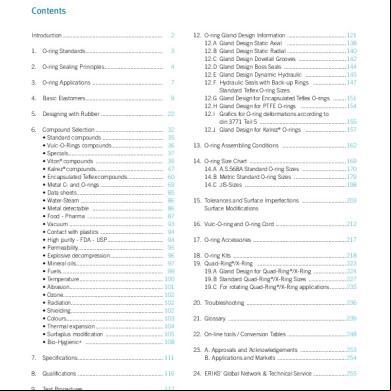
Eriks - O-rings - Technical Handbook 2n14k
December 2019 83
Tabela Anel Oring h3d3s
August 2022 0More Documents from "Christopher Garcia" 3t5p
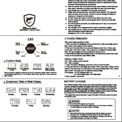
Shark Sport Watch Manual 6s2q4r
October 2019 146
Dytrancatalog2011_lowresolution (1) 5t55u
December 2019 42
Iso_17359_2018_en.pdf.pdf 6j4d3k
December 2019 31
Hytorc 383h1r
October 2022 0
14 - Eriks Nv - O-ring Technical Handbook - O-ring Gland Design - New 424q4i
December 2019 73