2.3.2.2 Packet Tracer - Configuring Rapid Pvst+ Instructions Ig 3u704l
This document was ed by and they confirmed that they have the permission to share it. If you are author or own the copyright of this book, please report to us by using this report form. Report 3b7i
Overview 3e4r5l
& View 2.3.2.2 Packet Tracer - Configuring Rapid Pvst+ Instructions Ig as PDF for free.
More details w3441
- Words: 997
- Pages: 4
Packet Tracer – Configuring Rapid PVST+ (Instructor Version) Instructor Note: Red font color or Gray highlights indicate text that appears in the instructor copy only.
Topology
Addressing Table Device
Interface
IP Address
Subnet Mask
Default Gateway
S1
VLAN 99
172.17.99.11
255.255.255.0
N/A
S2
VLAN 99
172.17.99.12
255.255.255.0
N/A
S3
VLAN 99
172.17.99.13
255.255.255.0
N/A
PC1
NIC
172.17.10.21
255.255.255.0
172.17.10.254
PC2
NIC
172.17.20.22
255.255.255.0
172.17.20.254
PC3
NIC
172.17.30.23
255.255.255.0
172.17.30.254
Switch Port Assignment Specifications Ports
Assignments
Network
S2 F0/6
VLAN 30
172.17.30.0/24
S2 F0/18
VLAN 20
172.17.20.0/24
S2 F0/11
VLAN 10
172.17.10.0/24
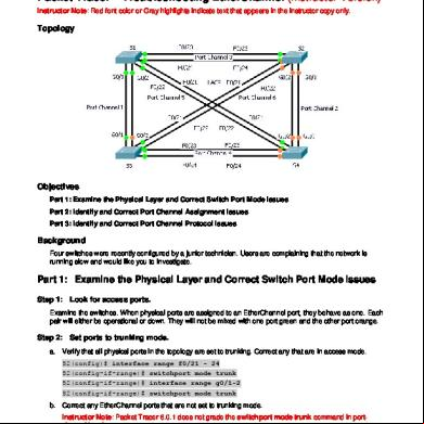
Objectives Part 1: Configure VLANs
© 2013 Cisco and/or its s. All rights reserved. This document is Cisco Public.
Page 1 of 4
Packet Tracer – Configuring Rapid PVST+ Part 2: Configure Rapid Spanning Tree PVST+ Load balancing Part 3: Configure PortFast and BPDU Guard
Background In this activity, you will configure VLANs and trunks, Rapid Spanning Tree PVST+, primary and secondary root bridges, and examine the configuration results. You will also optimize the network by configuring PortFast, and BPDU Guard on edge ports.
Part 1: Configure VLANs Step 1: Enable the ports on S2 in access mode. Refer to the topology diagram to determine which switch ports on S2 are activated for end- device access. These three ports will be configured for access mode and enabled with the no shutdown command. S2(config)# interface range f0/6,f0/11,f0/18 S2(config-if-range)# switchport mode access S2(config-fi-range)# no shutdown
Step 2: Create VLANs. Using the appropriate command, create VLANs 10, 20, 30, 40, 50, 60, 70, 80, and 99 on all of the switches. S1(config)# vlan S1(config-vlan)# S1(config-vlan)# S1(config-vlan)# S1(config-vlan)# S1(config-vlan)# S1(config-vlan)# S1(config-vlan)# S1(config-vlan)#
10 vlan vlan vlan vlan vlan vlan vlan vlan
20 30 40 50 60 70 80 99
S2(config)# vlan S2(config-vlan)# S2(config-vlan)# S2(config-vlan)# S2(config-vlan)# S2(config-vlan)# S2(config-vlan)# S2(config-vlan)# S2(config-vlan)#
10 vlan vlan vlan vlan vlan vlan vlan vlan
20 30 40 50 60 70 80 99
S3(config)# vlan S3(config-vlan)# S3(config-vlan)# S3(config-vlan)# S3(config-vlan)# S3(config-vlan)#
10 vlan vlan vlan vlan vlan
20 30 40 50 60
© 2013 Cisco and/or its s. All rights reserved. This document is Cisco Public.
Page 2 of 4
Packet Tracer – Configuring Rapid PVST+ S3(config-vlan)# vlan 70 S3(config-vlan)# vlan 80 S3(config-vlan)# vlan 99
Step 3: Assign VLANs to switch ports. Port assignments are listed in the table at the beginning of the activity. Save your configurations after asg switch ports to the VLANs. S2(config)# interface f0/6 S2(config-if)# switchport access vlan 30 S2(config-if)# interface f0/11 S2(config-if)# switchport access vlan 10 S2(config-if)# interface f0/18 S2(config-if)# switchport access vlan 20
Step 4: the VLANs. Use the show vlan brief command on all switches to that all VLANs are ed in the VLAN table.
Step 5: Assign the trunks to native VLAN 99. Use the appropriate command to configure ports F0/1 to F0/4 on each switch as trunk ports and assign these trunk ports to native VLAN 99. S1(config)# interface range f0/1-4 S1(config-if-range)# switchport mode trunk S1(config-if-range)# switchport trunk native vlan 99 S2(config)# interface range f0/1-4 S2(config-if-range)# switchport mode trunk S2(config-if-range)# switchport trunk native vlan 99 S3(config)# interface range f0/1-4 S3(config-if-range)# switchport mode trunk S3(config-if-range)# switchport trunk native vlan 99
Step 6: Configure the management interface on all three switches with an address. S1(config)# interface vlan99 S1(config-if)# ip address 172.17.99.11 255.255.255.0 S2(config)# interface vlan99 S2(config-if)# ip address 172.17.99.12 255.255.255.0 S3(config)# interface vlan99 S3(config-if)# ip address 172.17.99.13 255.255.255.0 that the switches are correctly configured by pinging between them.
© 2013 Cisco and/or its s. All rights reserved. This document is Cisco Public.
Page 3 of 4
Packet Tracer – Configuring Rapid PVST+
Part 2: Configure Rapid Spanning Tree PVST+ Load Balancing The Rapid Spanning Tree Protocol (RSTP; IEEE 802.1w) can be seen as an evolution of the 802.1D standard more so than a revolution. The 802.1D terminology remains primarily the same. Most parameters have been left unchanged so s familiar with 802.1D can rapidly configure the new protocol comfortably. In most cases, RSTP performs better than proprietary extensions of Cisco without any additional configuration. 802.1w can also revert back to 802.1D in order to interoperate with legacy bridges on a per-port basis.
Step 1: Configure STP mode. Use the spanning-tree mode command to configure the switches to use rapid PVST as the STP mode. S1(config)# spanning-tree mode rapid-pvst S2(config)# spanning-tree mode rapid-pvst S3(config)# spanning-tree mode rapid-pvst
Step 2: Configure Rapid Spanning Tree PVST+ load balancing. Configure S1 to be the primary root for VLANs 1, 10, 30, 50, and 70. Configure S3 to be the primary root for VLANs 20, 40, 60, 80, and 99. Configure S2 to be the secondary root for all of the VLANs. S1(config)# spanning-tree vlan 1,10,30,50,70 root primary S2(config)# spanning-tree vlan 1,10,20,30,40,50,60,70,80,99 root secondary S3(config)# spanning-tree vlan 20,40,60,80,99 root primary your configurations by using the show spanning-tree command.
Part 3: Configure PortFast and BPDU Guard Step 1: Configuring PortFast on S2. PortFast causes a port to enter the forwarding state almost immediately by dramatically decreasing the time of the listening and learning states. PortFast minimizes the time it takes for the server or workstation to come online. Configure PortFast on S2 interfaces that are connected to PCs. S2(config)# interface range f0/6 , f0/11 , f0/18 S2(config-if-range)# spanning-tree portfast
Step 2: Configuring BPDU Guard on S2. The STP PortFast BPDU Guard enhancement allows network designers to enforce the STP domain borders and keep the active topology predictable. The devices behind the ports that have STP PortFast enabled are not able to influence the STP topology. At the reception of BPDUs, the BPDU Guard operation disables the port that has PortFast configured. The BPDU Guard transitions the port into err-disable state, and a message appears on the console. Configure BPDU Guard on S2 interfaces that are connected to PCs. S2(config)# interface range f0/6 , f0/11 , f0/18 S2(config-if-range)# spanning-tree bpduguard enable
Step 3: your configuration. Use the show run command to your configuration.
© 2013 Cisco and/or its s. All rights reserved. This document is Cisco Public.
Page 4 of 4
Topology
Addressing Table Device
Interface
IP Address
Subnet Mask
Default Gateway
S1
VLAN 99
172.17.99.11
255.255.255.0
N/A
S2
VLAN 99
172.17.99.12
255.255.255.0
N/A
S3
VLAN 99
172.17.99.13
255.255.255.0
N/A
PC1
NIC
172.17.10.21
255.255.255.0
172.17.10.254
PC2
NIC
172.17.20.22
255.255.255.0
172.17.20.254
PC3
NIC
172.17.30.23
255.255.255.0
172.17.30.254
Switch Port Assignment Specifications Ports
Assignments
Network
S2 F0/6
VLAN 30
172.17.30.0/24
S2 F0/18
VLAN 20
172.17.20.0/24
S2 F0/11
VLAN 10
172.17.10.0/24
Objectives Part 1: Configure VLANs
© 2013 Cisco and/or its s. All rights reserved. This document is Cisco Public.
Page 1 of 4
Packet Tracer – Configuring Rapid PVST+ Part 2: Configure Rapid Spanning Tree PVST+ Load balancing Part 3: Configure PortFast and BPDU Guard
Background In this activity, you will configure VLANs and trunks, Rapid Spanning Tree PVST+, primary and secondary root bridges, and examine the configuration results. You will also optimize the network by configuring PortFast, and BPDU Guard on edge ports.
Part 1: Configure VLANs Step 1: Enable the ports on S2 in access mode. Refer to the topology diagram to determine which switch ports on S2 are activated for end- device access. These three ports will be configured for access mode and enabled with the no shutdown command. S2(config)# interface range f0/6,f0/11,f0/18 S2(config-if-range)# switchport mode access S2(config-fi-range)# no shutdown
Step 2: Create VLANs. Using the appropriate command, create VLANs 10, 20, 30, 40, 50, 60, 70, 80, and 99 on all of the switches. S1(config)# vlan S1(config-vlan)# S1(config-vlan)# S1(config-vlan)# S1(config-vlan)# S1(config-vlan)# S1(config-vlan)# S1(config-vlan)# S1(config-vlan)#
10 vlan vlan vlan vlan vlan vlan vlan vlan
20 30 40 50 60 70 80 99
S2(config)# vlan S2(config-vlan)# S2(config-vlan)# S2(config-vlan)# S2(config-vlan)# S2(config-vlan)# S2(config-vlan)# S2(config-vlan)# S2(config-vlan)#
10 vlan vlan vlan vlan vlan vlan vlan vlan
20 30 40 50 60 70 80 99
S3(config)# vlan S3(config-vlan)# S3(config-vlan)# S3(config-vlan)# S3(config-vlan)# S3(config-vlan)#
10 vlan vlan vlan vlan vlan
20 30 40 50 60
© 2013 Cisco and/or its s. All rights reserved. This document is Cisco Public.
Page 2 of 4
Packet Tracer – Configuring Rapid PVST+ S3(config-vlan)# vlan 70 S3(config-vlan)# vlan 80 S3(config-vlan)# vlan 99
Step 3: Assign VLANs to switch ports. Port assignments are listed in the table at the beginning of the activity. Save your configurations after asg switch ports to the VLANs. S2(config)# interface f0/6 S2(config-if)# switchport access vlan 30 S2(config-if)# interface f0/11 S2(config-if)# switchport access vlan 10 S2(config-if)# interface f0/18 S2(config-if)# switchport access vlan 20
Step 4: the VLANs. Use the show vlan brief command on all switches to that all VLANs are ed in the VLAN table.
Step 5: Assign the trunks to native VLAN 99. Use the appropriate command to configure ports F0/1 to F0/4 on each switch as trunk ports and assign these trunk ports to native VLAN 99. S1(config)# interface range f0/1-4 S1(config-if-range)# switchport mode trunk S1(config-if-range)# switchport trunk native vlan 99 S2(config)# interface range f0/1-4 S2(config-if-range)# switchport mode trunk S2(config-if-range)# switchport trunk native vlan 99 S3(config)# interface range f0/1-4 S3(config-if-range)# switchport mode trunk S3(config-if-range)# switchport trunk native vlan 99
Step 6: Configure the management interface on all three switches with an address. S1(config)# interface vlan99 S1(config-if)# ip address 172.17.99.11 255.255.255.0 S2(config)# interface vlan99 S2(config-if)# ip address 172.17.99.12 255.255.255.0 S3(config)# interface vlan99 S3(config-if)# ip address 172.17.99.13 255.255.255.0 that the switches are correctly configured by pinging between them.
© 2013 Cisco and/or its s. All rights reserved. This document is Cisco Public.
Page 3 of 4
Packet Tracer – Configuring Rapid PVST+
Part 2: Configure Rapid Spanning Tree PVST+ Load Balancing The Rapid Spanning Tree Protocol (RSTP; IEEE 802.1w) can be seen as an evolution of the 802.1D standard more so than a revolution. The 802.1D terminology remains primarily the same. Most parameters have been left unchanged so s familiar with 802.1D can rapidly configure the new protocol comfortably. In most cases, RSTP performs better than proprietary extensions of Cisco without any additional configuration. 802.1w can also revert back to 802.1D in order to interoperate with legacy bridges on a per-port basis.
Step 1: Configure STP mode. Use the spanning-tree mode command to configure the switches to use rapid PVST as the STP mode. S1(config)# spanning-tree mode rapid-pvst S2(config)# spanning-tree mode rapid-pvst S3(config)# spanning-tree mode rapid-pvst
Step 2: Configure Rapid Spanning Tree PVST+ load balancing. Configure S1 to be the primary root for VLANs 1, 10, 30, 50, and 70. Configure S3 to be the primary root for VLANs 20, 40, 60, 80, and 99. Configure S2 to be the secondary root for all of the VLANs. S1(config)# spanning-tree vlan 1,10,30,50,70 root primary S2(config)# spanning-tree vlan 1,10,20,30,40,50,60,70,80,99 root secondary S3(config)# spanning-tree vlan 20,40,60,80,99 root primary your configurations by using the show spanning-tree command.
Part 3: Configure PortFast and BPDU Guard Step 1: Configuring PortFast on S2. PortFast causes a port to enter the forwarding state almost immediately by dramatically decreasing the time of the listening and learning states. PortFast minimizes the time it takes for the server or workstation to come online. Configure PortFast on S2 interfaces that are connected to PCs. S2(config)# interface range f0/6 , f0/11 , f0/18 S2(config-if-range)# spanning-tree portfast
Step 2: Configuring BPDU Guard on S2. The STP PortFast BPDU Guard enhancement allows network designers to enforce the STP domain borders and keep the active topology predictable. The devices behind the ports that have STP PortFast enabled are not able to influence the STP topology. At the reception of BPDUs, the BPDU Guard operation disables the port that has PortFast configured. The BPDU Guard transitions the port into err-disable state, and a message appears on the console. Configure BPDU Guard on S2 interfaces that are connected to PCs. S2(config)# interface range f0/6 , f0/11 , f0/18 S2(config-if-range)# spanning-tree bpduguard enable
Step 3: your configuration. Use the show run command to your configuration.
© 2013 Cisco and/or its s. All rights reserved. This document is Cisco Public.
Page 4 of 4
Related Documents 3m3m1z

2.3.1.5 Packet Tracer - Configuring Pvst+ Instructions Ig 341s
December 2020 0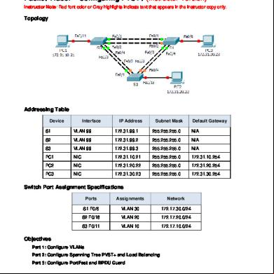
2.3.1.5 Packet Tracer - Configuring Pvst+ Instructions Ig 341s
October 2021 0
2.3.2.2 Packet Tracer - Configuring Rapid Pvst+ Instructions 4u4842
September 2021 0
2.3.2.2 Packet Tracer - Configuring Rapid Pvst+ Instructions Ig 3u704l
December 2019 53
2.3.1.5 Packet Tracer - Configuring Rapid Pvst+ Answer 2j5t6t
February 2022 0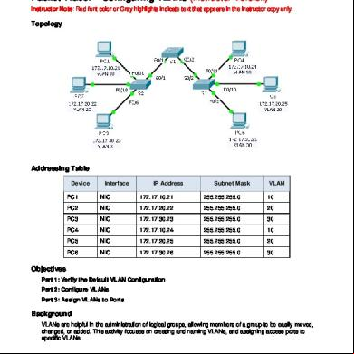
3.2.1.7 Packet Tracer - Configuring Vlans Instructions Ig 3q695j
December 2019 83More Documents from "Jose Affleck" 1q2j1l
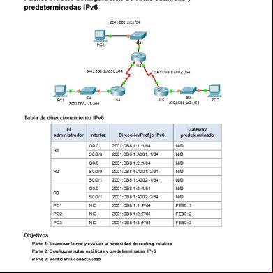
2.2.4.4 Packet Tracer - Configuring Ipv6 Static And Default Routes Instructions 6296w
May 2020 84
2.3.1.5 Packet Tracer - Configuring Pvst+ Instructions Ig 341s
October 2021 0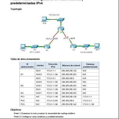
2.2.2.4 Packet Tracer - Configuring Ipv4 Static And Default Routes Instructions 4yxi
December 2019 219
2.3.2.2 Packet Tracer - Configuring Rapid Pvst+ Instructions Ig 3u704l
December 2019 53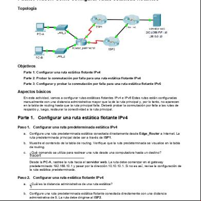
2.2.5.5 Packet Tracer - Configuring Floating Static Routes Instructions 135s6d
May 2020 20