Ansys Workbench 14 2r6h4t
This document was ed by and they confirmed that they have the permission to share it. If you are author or own the copyright of this book, please report to us by using this report form. Report 3b7i
Overview 3e4r5l
& View Ansys Workbench 14 as PDF for free.
More details w3441
- Words: 1,684
- Pages: 26
ANSYS WORKBENCH 14.0
Name: Cristóbal Jesús Valdepeñas Octavio Year: 3º Ingeniería Mecánica Escuela de Ingenieros Industriales de Albacete, UCLM. Introduction course to finite elements engineering with ANSYS Workbench.
1 Cristóbal Jesús Valdepeñas Octavio
ANSYS WORKBENCH 14.0
EXERCISE 1 1:
In this practice, we will use the design software SolidWorks to generate the structure on the image. After that, we will import it with the ANSYS module called “Design Modeler” in “IGS” format, the one which ANSYS is able to read. Besides, taking use of the big quantity of possibilities that the program has, we will test the structure with some kind of analyses, like the linear buckling or the modal module, seeing the stresses and the deformations. Mostly in huger structures, in many occasions, simplifying will be one of the most useful things we can do to make the calculations faster. To prove this, we will turn our 3D model to shells clicking on “Mid Surface” and we will transform the sections of our structure in lines, and the volume in shells. In addition, if the detail level we want to get is not too skilled, we could draw our porch in “Beam” elements, making them very simple and the calculations faster (just a line between two points and a cross section).
GEOMETRY DRAWING AND IMPORTING. As we are going to see in the images below, we have sketched our structure up with SolidWorks, following the IPE and HEB dimensions.
2 Cristóbal Jesús Valdepeñas Octavio
ANSYS WORKBENCH 14.0
Once we have both types of bar we are going to need, the next step is opening the assembly window.
3 Cristóbal Jesús Valdepeñas Octavio
ANSYS WORKBENCH 14.0
Now, we have made our structure in an external CAD program so we have to import it in ANSYS. Saving the file with ANSYS compatible format, “IGS”, we have to click on import file with an external CAD, and we will see something like this:
Going back to the Project screen, we have the materials definition left to do, so we go to Engineering Data, duplicate the Structural Steel we find on the window and assign a number to the Tensile Yield Strength and Compressive Yield Strength of each material.
4 Cristóbal Jesús Valdepeñas Octavio
ANSYS WORKBENCH 14.0
TEST WITH THE 3D GEOMETRY As far as the geometry and material definition is done, we start the Mechanical, define the s we have between our elements and the s with the ground.
After that, seeing the forces we have in the exercise, putting them on the structure is as easy as clicking on force, assign the face where it is going to be acting and write the coordinates of the vector that will define the force we are using.
5 Cristóbal Jesús Valdepeñas Octavio
ANSYS WORKBENCH 14.0
If we want to know the stresses of the structure and the total deformations, we have to put those analysis in the solution folder.
6 Cristóbal Jesús Valdepeñas Octavio
ANSYS WORKBENCH 14.0
Now we can compare results with other kind of programs because we have what we were looking for, numbers, deformations, stresses and the behavior of the current structure. But this is not all because we haven’t considered that our porch can suffer linear buckling or vibrations (can the Tacoma bridge, which went away with a very slow wind).
LINEAR BUCKLING: This kind of module will help us to know what the buckling is like. In order to know a determinate number of possibilities, in Analysis settings we can say how many options we want to get. In our case, we have chosen two (just not to calculate less common ways of buckling), as we can see below.
7 Cristóbal Jesús Valdepeñas Octavio
ANSYS WORKBENCH 14.0
If we choose the directional deformation, we could see which direction is going to be analyzed.
8 Cristóbal Jesús Valdepeñas Octavio
ANSYS WORKBENCH 14.0
MODAL: Vibrations in our model may be one of the points that we have to get under control, knowing the frequency in which the structure could have serious problems. In ANSYS, we have to add another environment to the static structural we were doing at first:
Going to the solutions, the stresses or the deformations are not as useful as in the static structural were because here we do not have forces, just the rigid matrix and the conditions (they could be optional, but if we define them, we would go to more specific ways of vibrations).
9 Cristóbal Jesús Valdepeñas Octavio
ANSYS WORKBENCH 14.0
10 Cristóbal Jesús Valdepeñas Octavio
ANSYS WORKBENCH 14.0
The more important results we have from this is the following paragraph with the summary.
SHELL SIMPLIFICATION As we said, the program gives us options to simplify geometries. For example, if we want to analyze our porch with shells, going to the Design Modeler, selecting Mid Surface and being careful with some aspects:
11 Cristóbal Jesús Valdepeñas Octavio
ANSYS WORKBENCH 14.0
Going to the Mechanical and defining again the loads and the s with the ground, the results we get are showed in the next image.
12 Cristóbal Jesús Valdepeñas Octavio
ANSYS WORKBENCH 14.0
13 Cristóbal Jesús Valdepeñas Octavio
ANSYS WORKBENCH 14.0
As we can see, the stresses and the deformations are almost the same, but the time that the program has spent to calculate the whole structure has been shorter in the shell one.
BEAM SIMPLIFICATION Opening a new Static Structural environment, defining the material properties and creating points with the Design Modeler, we define “lines from points” to represent the directrix of the bars that compose our porch.
If we keep defining the forces and the s, we will get the same results.
14 Cristóbal Jesús Valdepeñas Octavio
ANSYS WORKBENCH 14.0
Exercise 2: 2
GEOMETRY As we practiced how to create a new geometry, transform it to shell and beam and put many loads in it, we are going to make a little experiment. In the first case, we are going to study the assembly as an ideal piece, without welding. In the second case, we are going to add two prisms with triangular base to emulate the welding we have not put on the first case to see which are the differences.
Case 1: Making the object described in the image with SolidWorks:
Importing to ANSYS’s Design Modeler:
15 Cristóbal Jesús Valdepeñas Octavio
ANSYS WORKBENCH 14.0
Loading the forces in the hole of the vertical piece:
It could have been done with the “bearing load” which charges a load produced by a cylindrical object that goes through that hole.
16 Cristóbal Jesús Valdepeñas Octavio
ANSYS WORKBENCH 14.0
Case 2: Adding the triangular base prisms to the piece:
17 Cristóbal Jesús Valdepeñas Octavio
ANSYS WORKBENCH 14.0
Conclusion: as we can see if make zoom to the place of the piece that one part with the other, the strains are higher in the piece without the welding:
18 Cristóbal Jesús Valdepeñas Octavio
ANSYS WORKBENCH 14.0
(Red arrow with the worst strain) This exercise could be simulated with shells, but as the objective we had was to see the differences between the welded piece and the other and we cannot create the welding as a line or a shell in a very precise way, we chose the 3D analysis. Anyway, the result of clicking on Mid Surface and connecting both faces un the first case:
19 Cristóbal Jesús Valdepeñas Octavio
ANSYS WORKBENCH 14.0
EXERCISE 3 3
This analysis will be useful to compare the effects of deg the structure with revolute ts or rigid ts.
CASE 1: TED STRUCTURE GEOMETRY Building the structure with linear elements:
20 Cristóbal Jesús Valdepeñas Octavio
ANSYS WORKBENCH 14.0
STRAINS AND DEFORMATIONS:
Writing the material characteristics, putting on the structure de loads and charging the s, we get those results, which ones are not too difficult to obtain after the first and the second exercises done.
21 Cristóbal Jesús Valdepeñas Octavio
ANSYS WORKBENCH 14.0
CASE 2: FIXED STRUCTURE GEOMETRY This test is very fast because we only have to change the kind of ts that we want to use in this part of the Mechanical:
After that, clicking on solving, we get the new solutions of our loaded structure so we can compare both cases:
22 Cristóbal Jesús Valdepeñas Octavio
ANSYS WORKBENCH 14.0
At first, we were hoping to get different results, but as we can see, the two horizontal bars are continue so it is supposed to have bending moments in both cases. If these bars were not continue, in the ted structure would have just axial forces.
23 Cristóbal Jesús Valdepeñas Octavio
ANSYS WORKBENCH 14.0
DEFORMATIONS TED STRUCTURE
FIXED STRUCTURE
AXIAL FORCES TED STRUCTURE
FIXED STRUCTURE
At the end of this exercise, we needed to see what happened with the 3D structure so we sketched it in Solid Works and made an analysis in ANSYS workbench. That moment was when we noticed that sometimes we need to simplify our model in order not to spent almost ten minutes calculating a little structure like this one.
24 Cristóbal Jesús Valdepeñas Octavio
ANSYS WORKBENCH 14.0
3D MODEL
The results differ more than in the other solutions, but we suppose that it is because of the geometry and the conditions we have written.
25 Cristóbal Jesús Valdepeñas Octavio
ANSYS WORKBENCH 14.0
CONCLUSSIONS: The course has been useful because I have learnt how to use two programs on the same time. One of them has been the Workbench, which was the main object of the lessons. The other has been the design software of Solid Works. I did not have any idea about how to use one or the other but I could spend hours and hours investigating about their working. After having taken five lessons of four hours each, it seems to have been too short, but the course has opened a lot of possibilities. In my opinion, once we know how to use the main options and the basic commands of a software, you just have to look for exercises on the internet or simply satisfy the need of feed our curiosity.
Thermal analysis
26 Cristóbal Jesús Valdepeñas Octavio
Related Documents 3m3m1z

Ansys Workbench 14 2r6h4t
December 2019 41
Ansys Workbench 14 Cadcim 6y6u5l
December 2019 65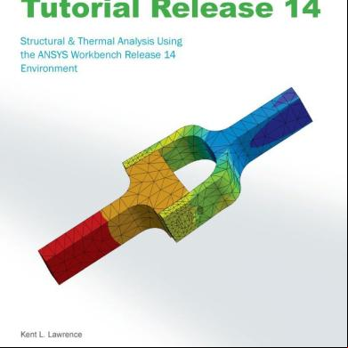
Ansys Workbench Tutorial Release 14 254ip
October 2019 59
Ansys Workbench 5d6m1h
February 2021 0
Ansys Workbench 14 - A Tutorial Approach 3r523l
December 2021 0
Explicit Ansys Workbench 14 Manual 4x5a5z
October 2022 0More Documents from "Cristóbal Jesús Valdepeñas Octavio" 635r6l
Cuando-estoy-enfadado.pdf 6y2h2c
June 2021 0
6l6m1j
April 2020 49
Sistemas De Informacion Geografica 1i617
July 2020 0
Just Juliet Charlotte Reagan 215p22
September 2022 0
C#ccgenerator 2sw6i
February 2023 0