Black Max - Mud Motor - Operations Manual 1s1x
This document was ed by and they confirmed that they have the permission to share it. If you are author or own the copyright of this book, please report to us by using this report form. Report 3b7i
Overview 3e4r5l
& View Black Max - Mud Motor - Operations Manual as PDF for free.
More details w3441
- Words: 29,457
- Pages: 129
INTRODUCTION
The NQL Energy Services Operations Manual covers basic procedures and principals in the operation of BlackMax positive displacement mud motors, drilling jars and shock tools.This manual includes basic operating information, specifications and tool parameters and also provides general information for the to operate our equipment safely and effectively. As always, specific applications may dictate changes in procedures, therefore this manual is to be used as a guideline only. If there are any questions, please your nearest NQL Energy Services representative. This manual is divided into sections dealing with motors, jars and shock tools. It also includes basic engineering data for use at the rig. In addition, specifications for each motor power section are available to help the identify the proper power section for optimum drilling performance.
Printed in Canada Jan 2006
I N T R O D U C T I O N
Table of Contents FISHING DRAWINGS AND MEASUREMENTS
DRILLING TOOLS PRODUCT LINE BlackMax Mud Motors Specifications Optional Equipment Formulas Fluids Motor Shipping Weights Torque Connections Build Rates Setting Procedures for ABH
1 10 60 61 66 69 70 72 76
Mud Motor Fishing Dimensions
89
Shock Tool Fishing Dimensions
99
Drill Collar Weights
111
BlackMax Shock Tools
78
Annular Capacities
113
BlackMax Rayson Mechanical Jars
81
Hole Capacity
114
BlackMax Hydraulic Mechanical Jars
83
Drill Pipe Capacities
116
BlackMax Best Hitter Mechanical Jars
85
Drill Pipe Properties
117
BlackMax Rig Rattler Hydraulic Jars
87
Nozzle Flow Areas
118
Mechanical Jars Fishing Dimensions
103
Hydraulic Mechanical Jar Fishing Dimensions
105
HELPFUL TABLES AND INFORMATION Casing Dimensions
108
Rotary Connection Cross Reference
110
Mud Weights
120
Conversions
123
Locations
126
C O N T E N T S
NQL Energy Services Product Line
1
NQL's BlackMax line of quality drilling tools includes drilling motors, shock tools, two types of mechanical drilling jars, a hydraulic mechanical drilling jar, and a hydraulic drilling jar. In sizes ranging from 1 11/16" OD to 11 1/4" OD, NQL has a drilling tool for any application. BlackMax Mud Motors range in size from 1 11/16"OD to 11 ¼" OD. With over 80 different configurations, BlackMax Mud Motors provide our customers with the versatility to tailor the motor to a specific bit and drilling application. With our combinations of power sections, rugged drive shafts, and sealed thrust bearing assemblies BlackMax can build the exact tool to perform the job to the highest quality expected of their customers. BlackMax Mud Motors have drilled hundreds of thousands of feet of hole by marrying the power section you need with the bit required in the application. Black Max Shock Tools range in size from 2 7/8" OD to 11" OD. Designed to cushion heavy axial loading and reduce bit vibrations, BlackMax Shock Tools will extend drillstring component and bit life to help reduce drilling costs. BlackMax Shock Tools are sprung for compression and tension, are pressure balanced from hydrostatic pressures, and come in string or bottom hole configurations. BlackMax Rayson Mechanical Jars and Best Hitter Mechanical Jars are designed to create powerful mechanical jarring action to free drill strings that have become stuck. They are oil lubricated and are designed to work in the harshest of drilling environments. BlackMax Hydraulic Mechanical Jars have a mechanical latch feature that keeps the jar in the neutral position and prevents unexpected jarring while tripping in or out of the hole. The jars have a hydraulic valve that creates a time delay when the jar is in operation and the latch is disengaged. BlackMax "Rig Rattler" Jars are a hydraulic tool that jars up and has a mechanical "bump" down. The Rig Rattler has been a proven solution to stuck pipe in many applications, and provides a maximum jar action when needed most.
M U D M O T O R D E S I G N
M U D Bearing Assembly (A) Each BlackMax drilling motor comes equipped with a fully sealed, oil lubricated bearing system. Bearings are configured to accommodate high speed/low torque or low speed/high torque, without altering radial or axial loading.
Universal t Assembly (B) The BlackMax universal t is used to convert the eccentric motion of the motor (rotor) to a smooth concentric motion required by the bearing section. The design of sealed universal ts and a connecting rod, allows the motor to operate at high bent housing angles, yet still be able to handle high torque and speed.
Power Sections (D) BlackMax power sections are made up of a lobed rotor that fits inside an elestomer lined housing (stator). The rotor has one less lobe than the stator, creating a continuously sealing chamber. Drilling fluid or gas is forced through the motor, thereby turning the rotor and generating torque. Where drilling requirements call for circulation rates exceeding maximum recommended rates, rotors are jetted to allow excessive fluid to flow down a parallel path, thereby reducing damage to the elastomer in the stator.
Adjustable Bent Housing/Fixed Housing (C) BlackMax adjustable housings are available in 0°-3° settings, and include a specialized assembly for short radius drilling. The housing is easily adjustable and allows the operator to reset angles at the rig floor, eliminating the need to change assemblies or motors. Always follow the specifications for proper torquing of the assembly. (See pg. 75 - 76 for proper procedures)
Dump Valve/Blank Sub (E) optional (see your dealer for more details)
M O T O R D E S I G N
2
Introduction This section describes basic operating procedures, which are used in the field and will facilitate proper operation of BlackMax motors.
3
Bit Selection An important aspect of any planned downhole motor run, is properly matching the bit and hydraulics to the motor in order to achieve the desired results. Attention must be given to TFA (total flow area) to see that proper parameters are maintained with regard to pressure drop across bit, annular velocity needed for hole cleaning, maximum standpipe pressure, and adequate hole cleaning at the bit\formation interface. Keep in mind that stall pressure of a motor may approach pump relief valve limits in some cases. In larger hole sizes, a bored rotor may be necessary to accommodate fluid requirements mentioned above. Generally, all motor sizes have adequate torque to run any cone type bit. Abrassive PDC bits may cause stalling in rough and broken formations. If the purpose of the run is to build angle, or otherwise achieve significant deviation, gauge length on the bit is very important. Gauge protection is necessary if the motor is bent, since continual side loading occurs at the bit.
Surface Testing (& Orientation) The BlackMax motor is a sealed bearing motor, so it may be safely surface tested with or without a bit attached, since bit pressure drop is not necessary to cool the bearings. It is recommended that a bit not be attached if the motor is significantly bent, and needs to be positioned in the BOP's (blow-out preventers) or, below to accommodate testing of the dump valve. If the downhole motor is tested in this manner, be sure to remove the bit box thread protector before lowering the motor into the hole. When the downhole motor is equipped with a dump valve, attach the kelly and lower the ports just below the top of the bell nipple before starting the pump. Carefully observe the closing of the dump valve as the pump is eased up. After the valve is closed, ease up on the pump. Left-hand torque should be noted in the assembly. Vibration may be seen as flow rates increase, but is normal and no cause for concern. Before shutting the pump down, be sure that the dump valve is in position in the bell nipple. When the pump is shut down, if the pressure doesn't bleed off, open the fill-up line on the standpipe to relieve the pressure. When turning the bit box with tongs during the course of a coiled tubing operation, turn the box to the left, otherwise a back-off could occur. Pick the motor up, and attach the selected bit. If a bent housing adjustment is needed, lower the motor down to the adjustable housing, and make the
P R O C E D U R E S
needed change according to the accompanying setting procedure (see pg. 75 - 76). Upon completion of the setting procedure, mark the tool face, and slowly lower the motor into the hole, keeping tool face alignment as you go. At this point, you can align and test whatever steering device is to be used, and proceed on in the hole. Please note, motors are pre-tested in water and should be properly thawed before surface testing when operating in sub-zero temperatures.
Running In We recommend running a float valve with the downhole motor, especially if a dump valve assembly is used. This keeps trash out of the ID of the string. If no dump valve is used, the float will keep the motor from running backward as the pipe fills up. If heat is a factor, it is a good idea to break circulation once or twice as you approach bottom. Pumping should be at a slow rate and kept up long enough to move some cool mud down to the motor. Reciprocation of the drill string up and down during the pumping operation will keep casing wear to a minimum, and decrease the likelihood of leaving a ledge if the motor is in open hole. If the motor bend is extreme, keep running speeds slow to minimize the chance of ledging. Running speeds should also be slow when dealing with high mud weights and small liners, as pressure surges might knock the bottom out at the liner shoe. Drilling Drilling with a downhole motor is monitored mainly by changes in standpipe pressure. The amount of torque created at the bit face will be reflected by an increase in standpipe pressure over the "off bottom" reading. This difference in pressure is called “differential pressure”. The maximum motor differential pressure indicated in the downhole motor specifications is the total differential recommended. It takes from 10 to 15% of that total to turn the rotor in the off bottom position. The difference is the amount that is usable with WOB (weight-on-bit).
P R O C E D U R E S
When tagging bottom for the first time, keep in mind that a new bottom pattern needs to be established, especially if a different assembly or a different bend is employed. Higher differential pressures will be noted with less bit weight if PDC (drag) bits are used. Regular diamond bits will increase standpipe pressure slightly when bottom is tagged due to the reduction in flow area around the bit face. Whether the drilling operation is sliding or rotating, we recommend keeping differential at 60-75% of the maximum motor differential noted in the specifications. ROP (rate of penetration) is a function of rpm and bit geometry and formation.
4
Good weight transfer is normally accomplished with rotation of the drill string. Optimization of ROP can be attained with incremental changes of WOB. We recommend (for sections of hole where long rotation periods are anticipated) that bends be kept to a maximum of 1.5° (actual) and surface rotary speed be kept below 90 rpm.
5
Special precautions should be considered if high temperature is a factor in the well. The stator elastomer may swell and begin to fail. Pumps should be brought up to speed slowly to allow the rotar to begin turning, and then gradually increased to ease the shock loading of the swollen elastomer. Stall Indication/ Reaction A motor stall is indicated be a sudden increase in standpipe pressure while drilling. When a stall occurs, it is important to cut back pump strokes before lifting the motor off bottom. This reduces the pressure in the power section and will allow the driller to restart the motor. Pulling Out Care should be taken when pulling a bent housing motor through the BOP stack. A bent motor may damage the internal components of the stack. A check of the bearing stack oil should be made to determine if the motor should be re-run. Then procedure to check the oil is as follows:When picking the motor up to break the bit off, a water hose can be tied off in the top of the motor (if a hollow lift nipple is available). Place the bit in the bit breaker, put the lead tongs on the bearing housing to hold back up, and carefully bump the rotary intermittently to the right. If the bit output shaft is locked, lay the motor down. If the bit turns freely, engage the rotary and turn the bit slowly, turn the water on, and pump water through the downhole motor until it cleans up at the bit nozzles. Break the bit off the downhole motor. If a dump valve assembly is being used, be sure to flush the assembly thoroughly until clear water flows through the ports. If a re-run is being considered, a check of the oil left in the bearings is essential and can be described as follows:
P R O C E D U R E S
Above the bit box there is a large snap ring. Behind this ring is a piston assembly that moves away from the snap ring as oil seepage occurs. By measuring the distance from the bearing housing shoulder to the piston, and referring to the Piston Depth Chart below, the advisability of re-running the motor can be determined.
Tool Size 1 11/16” 2 1/16” 2 3/8” Short 2 7/8” Short 3 1/8” 3 3/8” 3 3/4” 4 1/8” 4 3/4” Short 5” 5” Series 3 5 1/2”
Piston Depth (in) “A” 9/16” 1” 1” 1 9/16” 1” 1 1/4” 7/8” 1 5/8” 2 1/8” 7/8” 7/8” 2 1/4”
Piston Depth (in) “A” 6” 1 7/8” 6 1/4” 1 3/8” 1 3/8” 6 1/2” & 6 1/2 S3 1 3/8” 6 3/4” & 6 3/4 S3 2 3/4” 7 1/2” & 7 1/2 S3 8” 3 1/2” 7/8” 8” Series 3 2 1/8” 9 5/8” 9 5/8” Series 3 3” 3 5/8” 11 1/4” Tool Size
P R O C E D U R E S
6
Motor Applications
7
NQL Energy Services now supplies one of the largest range of motor sizes available. It is this variety that allows us the flexibility to participate in almost any application with maximum performance. Performance\Straight Hole Drilling With the continued development of PDC bits and more powerful power sections, it has become cost effective to pair the two when long straight hole sections are to be drilled. NQL Energy Services offers a full line of motors that have proven themselves in very deep, hot, high mud weight, small hole applications. The savings recognized by operators due to reduced tubulars cost and savings in mud systems far outweighs the cost of conventional drilling at depth. Directional\Steerable Drilling NQL Energy Services motors offer a surface adjustable bent housing that provides directional drillers with flexibility in the planning and execution of any directional drilling project. The 3° adjustable housing allows the drilling of any conventional open hole kick-off or sidetrack operation.The motors can be oriented with single shot surveys, magnetic or gyroscopic wireline steering tools and measurement-while-drilling tools. If a steerable system is to be used, NQL Energy Services motors again display their versatility with the field replacable bearing housing stabilizer. Steerable systems are invaluable to wells that have multiple targets, or complex approach paths that are the result of geological constraints.The stabilization provided is normally 1/8 to 1/4 inch less than the hole gauge and can be tailored to the individual needs of the directional driller.
A P P L I C A T I O N S
Horizontal / Short Radius Drilling NQL Energy Services has a range of motor sizes suited to horizontal and short radius applications in various hole sizes. NQL Energy Services motors have performed medium radius projects with build rates ranging from 10°-45°/100'. Short radius (46°-95°/100 ft.) and ultra-short radius projects (96°-128°/100 ft.) are also becoming more commonplace. For angle building purposes, motors can be run with or without a near bit stabilizer and in many different configurations i.e. single bend, double bend, or with a flex t in place of a second bend at the top of the motor. The flex t allows limited rotation during the build section to fine tune the build rate. When rotating in the lateral section we recommend a bent housing maximum setting of 1.5°. This should be sufficient for minor course corrections as drilling proceeds.
Remedial\Workover Operations NQL Energy Services provides a wide variety of power section options and motor sizes that will accommodate almost any remedial need. Trying to rotate a small limber work string at depth with a power swivel is difficult in a deviated hole. Drilling out cement and guide shoes in small liners is efficiently and cost effectively accomplished by utilizing NQL Energy Services downhole motors.
Coiled Tubing NQL Energy Services motors have been used for years to provide a power source for coiled tubing remedial operations. Recently, NQL Energy Services motors have been used in the industry for drilling new holes. Torque restrictions in the coiled tubing so far have limited hole size applications, but drilling rates have been impressive, using both fluid and air as a circulating medium.
A P P L I C A T I O N S
8
River Crossing\Utility Boring
9
NQL Energy Services is a recognized leader in the river crossing and utility boring industry. With crossing projects being undertaken in formations with considerable compressive strength, the addition of downhole motors with high torque deliverability and built in directional capabilities was inevitable. The sealed bearing assembly protects the bearing section when solids control is less than perfect. The wide range of rotor/stator configurations have proven to be invaluable to contractors who engage in the highly specialized crossing business. In a typical crossing operation, the bit enters the ground at an angle less than horizontal, proceeds down under the object to be crossed. It is then brought horizontal, and then back up to an exit point on the other side. The assembly is guided with a wireline steering tool, or a surface interactive instrument that can track the bit from above ground. The downhole motor is used on the pilot hole operation, with subsequent hole opening operations bringing the borehole to required diameter. Small diameter motors are being used more and more for utility boring operations in urban areas to install fiber optic cables and other utility conduits. The NQL Energy Services downhole motors have proven themselves to be cost-effective when compared to alternative horizontal boring methods. Guidance for these bores is similar to that described above.
A P P L I C A T I O N S
SPECIFICATIONS Horsepower: To determine the horsepower you must know the rpm and the torque at which you are running.
The performance graphs that accompany the specifications show maximum differential working (on/off bottom) pressure, torque, rpm, and horsepower as follows:
5252
=
133 × 1600 ft ⋅ lb 5252
320 280
2,400 2,100 1,800
200
1,500
{
rpm - 175 gpm
160
1,200
PRESS LOSS
120
900
rpm - 100 gpm
M O T O R S
600
PRESSURE DIFFERENTIAL psi
800
700
600
500
400
300
300
40
TO R
QU
E
PRESS LOSS
200
Rpm: To read rpm, find the line labeled 'rpm-175 gpm', and follow it to where it intersects the line labeled 'MAX. DIFF.'. Reading across the graph to the left, the rpm is 133 rpm.
80
100
It is offset to the left of the 'MAX. DIFF.' line by an amount equal to the pressure loss (75 psi). Reading this line across the graph to the right will give you a Torque reading. For this example, torque is 1600 ft-lb.
TORQUE ft lb
PRESS LOSS
{
SPEED rpm
240
M U D
= 40.5
{
rpm - 250 gpm
Working Pressure: Due to losses from friction, turbulence, and pressure, the Working Pressure will be less than the Maximum Pressure Differential: To determine the working pressure at 175 gpm, find the line marked 'rpm-175 gpm'. There is 75 psi indicated on the graph as 'Press. Loss'. This is the pressure loss through the motor at 175 gpm with no load on the bit. Therefore, Effective Pressure = 600 psi - 75 psi = 525 psi
rpm × torque
hp =
Maximum Pressure Differential: This is the maximum designed pressure dropped across the illustrated power section. It is indicated on the graph as 'MAX. DIFF.'. In this case, the pressure differential is 600 psi. For optimum performance and life, this pressure should not be exceeded.
MAX DIFF.
The following sections show specifications recommended for the proper operation of BlackMax motors.
10
1 11/16”
11
1 11/16” 1 11/16” 1-2, 3 Stage 40
MAX DIFF.
2,000 rpm - 35 gpm
1,750
35
Max Pressure Drop
10,342 kPa
450 psi
Max Diff. Pressure
3,103 kPa
86”
0/A Length
2,184 mm
For more information on our products see our Web site http://www.nql.com
30
1,500
25 20
1,000 rpm - 15 gpm
15 U
E
750 R TO
5
600
525
450
375
300
75
255
250
PRESSURE DIFFERENTIAL psi
Volume
Bit to Bend Length
Speed
Torque
(lpm)
(gpm)
(rpm)
(ft-lb)
57 95 132
15 25 35
534-797 9761,238
25 25 25
hp
2.5 4.6 7.1
22"
559
Bottom Connection
AW-ROD
Bearing Load (compression)
dynamic=2,500 lb
1,110 daN
static=6,000 lb
2,670 daN
Bearing Load (tension)
dynamic=2,500 lb
1,110 daN
static=6,000 lb
2,670 daN
Max. Overpull (for re-runs)
6,000 lb
2,670 daN
28,000 lb
12,455 daN
10
Q
500
TORQUE ft lb
rpm - 25 gpm
1,250
150
SPEED rpm
1500 psi
Absolute Overpull
M U D M O T O R S
3,302 mm
E
10
600
525
450
375
300
255
75
150
TO R
QU
125
PRESSURE DIFFERENTIAL psi
Speed
Torque
(lpm)
Volume (gpm)
(rpm)
(ft-lb)
57
15 30
100-212
62
114
310-430
57
170
45
540-645
50
hp
Bearing Load (compression)
dynamic=2,500 lb
1,110 daN
static=6,000 lb
2,670 daN
Bearing Load (tension)
dynamic=2,500 lb
1,110 daN
static=6,000 lb
2,670 daN
Max. Overpull (for re-runs)
6,000 lb
2,670 daN
28,000 lb
12,455 daN
MAX DIFF.
AW-ROD
rpm - 25 gpm
400 300 E
Bottom Connection
100
500
U
559
200
Q
20
22"
R
30
250 rpm - 15 gpm
Bit to Bend Length
120
80 60 40
TO
375
40
20
100
100
rpm - 30 gpm
SPEED rpm
MAX DIFF.
500
TORQUE ft lb
50
625
rpm - 35 gpm
600
rpm - 45 gpm
Volume
Speed
Torque
(gpm)
(rpm)
(ft-lb)
1.2
95
25
130-400
125
3.1
3.4
132
35
300-575
120
6.8
5.1
170
45
450-720
116
9.9
1 11/16”
M U D M O T O R S
PRESSURE DIFFERENTIAL psi
(lpm)
Absolute Overpull
TORQUE ft lb
0/A Length
140
700
800
130”
160
rpm - 45 gpm
700
2,438 mm
800
5,171 kPa
600
0/A Length
750 psi
10,342 kPa
Max Diff. Pressure
500
96”
60
750
3,103 kPa
PERFORMANCE 1 11/16” 1 11/16” 5-6, 5 Stage
400
450 psi
70
875
10,342 kPa
Max Diff. Pressure
Max Pressure 1500 psi Drop
300
80
1,000
SPEED rpm
Max Pressure 1500 psi Drop
200
1 11/16” 1 11/16” 5-6, 3 Stage
hp
12
1 11/16”
Stator Configuration 1 11/16” PERFORMANCE 1 11/16” 5-6, 5 Stage ML Volume (gpm) Speed (rpm) Torque (ft-lb) Bearing Assembly 125 - 400 1 11/16” 25 43 mm 125 Volume 290 - 560 121 35 25 - 45 gpm 95 - 170 lpm Speed 115 125 - 720 rpm 445 - 720 45 125 - 720 rpm Torque 169 N*m 125 ft - lb Max. Pressure Drop 1,500 psi 10,342 kPa Max. Diff. Pressure 5,171 kPa 750 psi Bit to Bend Length 22” 559 mm O/A Length 3,302 mm 130” 1 7/8” - 3” Hole Size 48 - 76 mm Top Connection AW - ROD AW - ROD Bottom Connection AW - ROD AW - ROD dynamic = 2,500 lb 1,110 daN Bearing Load (compression) static = 6,000 lb 2,670 daN dynamic = 2,500 lb 1,110 daN Bearing Load (tension) static = 6,000 lb 2,670 daN Max. Overpull 6,000 lb 2,670 daN (for re-runs)
Absolute Overpull
28,000 lb
12,455 daN
13
hp 3.0 6.7 9.7
M U D M O T O R S
2 1/16” 2 1/16” 1-2, 2 Stage 40
MAX DIFF.
1,600 1,400 rpm - 45 gpm
35
25 20
rpm - 25 gpm
15 QU
E
600
10
TO R
400
5
400
350
300
250
200
150
100
200
PRESSURE DIFFERENTIAL psi
Volume
Speed
Torque
hp
(lpm)
(gpm)
(rpm)
(ft-lb)
95 132
25
575-683
25
2.7
35
852-960
25
4.1
170
45
1,111-1,219
25
5.3
TORQUE ft lb
rpm - 35 gpm
50
SPEED rpm
800
Max Pressure Drop
10,342 kPa
300 psi
Max Diff. Pressure
2,068 kPa
105”
0/A Length
2,667 mm
For more information on our products see our Web site http://www.nql.com
30
1,200 1,000
1500 psi
Bit to Bend Length
29"
Bottom Connection
AW-ROD
Bearing Load (compression)
dynamic=8,375 lb
3,725 daN
static=5,800 lb
2,580 daN
Bearing Load (tension)
dynamic=3,350 lb
1,490 daN
static=2,300 lb
1,025 daN
Max. Overpull (for re-runs)
2,300 lb
1,025 daN
Absolute Overpull
33,500 lb
14,900 daN
2 1/16”
737 mm
M U D M O T O R S
14
2 1/16”
Max Pressure Drop
10,342 kPa
155 psi
Max Diff. Pressure
1,069 kPa
300 psi
Max Diff. Pressure
2,068 kPa
350
82”
0/A Length
2,083 mm
110”
0/A Length
2,794 mm
300
Volume (lpm)
(gpm)
Speed
Torque
(rpm)
(ft-lb)
hp
AW-ROD
Bearing Load (compression)
dynamic=8,375 lb
3,725 daN
100
static=5,800 lb
2,580 daN
50
Bearing Load (tension)
dynamic=3,350 lb
1,490 daN
static=2,300 lb
1,025 daN
Max. Overpull (for re-runs)
2,300 lb
1,025 daN
Absolute Overpull
33,500 lb
14,900 daN
MAX DIFF.
80
150
60
rpm - 20 gpm
40
400
350
300
20
250
200
175
150
125
75
100
PRESSURE DIFFERENTIAL psi
Bottom Connection
737 mm
100
rpm - 35 gpm
200
E QU
50
TO R
10
29"
120
200
150
20
100
250
140
E
30
rpm - 50 gpm
Bit to Bend Length
160
QU
40
rpm - 20 gpm
400
PRESSURE DIFFERENTIAL psi
Speed
Torque
(lpm)
Volume (gpm)
(rpm)
(ft-lb)
hp
76
20
92-118
52
0.9
76
20
100-123
110
2.2
132
35
187-213
43
1.5
132
35
190-213
108
3.9
189
50
277-303
39
2.0
189
50
285-308
98
5.3
TORQUE ft lb
1500 psi
100
50
150
50
10,342 kPa
50
60
rpm - 35 gpm
25
SPEED rpm
200
70
TORQUE ft lb
rpm - 50 gpm
300 250
Max Pressure Drop
SPEED rpm
MAX DIFF.
350
2 1/16” 2 1/16” 4-5, 2 Stage
1500 psi 80
400
15
TO R
Hot Hole 2 1/16” 2 1/16” 4-5, 1 Stage
M U D M O T O R S
2 3/8” 2 3/8” 1-2, 7 Stage
2 3/8” 2 3/8” 2-3, 4 Stage
90 rpm - 45 gpm
dynamic=3,525 lb
1,570 daN
static=2,650 lb
1,180 daN
2,650 lb
1,180 daN
hp
Max. Overpull (for re-runs) Absolute Overpull
40,500 lb
18,015 daN
375
45
MAX DIFF.
Bearing Load (tension)
3,915 daN
60 rpm - 20 gpm
250 UE
30
RQ
125
15
TO
600
889 mm
525
35"
75
500
M U D M O T O R S
PRESSURE DIFFERENTIAL psi
Volume
Speed
Torque
(lpm)
(gpm)
(rpm)
(ft-lb)
hp
76
20
400-549
85
6.5
76
20
168 - 287
95
132
35
815-963
85
13.2
170
45
534 - 634
93
9.5
189
50
1,215-1,363
85
19.6
246
65
814 - 912
91
14.1
2 3/8”
TORQUE ft lb
105
750
450
1,050
900
750
600
450
(ft-lb)
Bit to Bend Length
2,960 daN
E
(rpm)
875
625
static=6,650 lb
QU
(gpm)
3,658 mm
BW-ROD
TO R
300
(lpm)
0/A Length
dynamic=8,800 lb
PRESSURE DIFFERENTIAL psi
Torque
144”
3,820 kPa
Bearing Load (compression)
30
Speed
4,343 mm
Max Diff. Pressure
Bottom Connection
15
Volume
554 psi
1,200
45
0/A Length
6,067 kPa
375
MAX DIFF.
rpm - 20 gpm
400 200
60
Max Diff. Pressure
300
75
TORQUE ft lb
171” rpm - 35 gpm
800 600
880 psi
120 rpm - 65 gpm
225
1,200
90
10,342 kPa
150
105
10,342 kPa
1000
75
1,400
150
SPEED rpm
rpm - 50 gpm
Max Pressure 1500 psi Drop
SPEED rpm
1,600
1,000
Max Pressure 1500 psi Drop
120
3.0
16
2 3/8”
Torque
(rpm)
(ft-lb)
10
79-99
97
15
129-149
96
25
227-247
95
38 57 95
2,870 mm
hp
525
Bit to Bend Length
35"
Bottom Connection
BW-ROD
Bearing Load (compression)
dynamic=8,800 lb
3,915 daN
static=6,650 lb
2,960 daN
Bearing Load (tension)
dynamic=3,525 lb
1,570 daN
static=2,650 lb
1,180 daN
Max. Overpull (for re-runs)
2,650 lb
1,180 daN
Absolute Overpull
40,500 lb
18,015 daN
889 mm
450 375
175 150 125
rpm - 50 gpm
100
300 rpm - 35 gpm
75
225 rpm - 20 gpm
150 75
50 25
PRESSURE DIFFERENTIAL psi
Volume
Speed
Torque
(rpm)
(ft-lb)
hp
(lpm)
(gpm)
1.5
76
20
96-138
115
2.1
2.4
132
35
201-243
100
3.8
4.1
189
50
303-345
90
5.2
TORQUE ft lb
0/A Length
600
113”
525
2,896 mm
450
0/A Length
MAX DIFF.
114”
200
375
2,565 kPa
300
600
525
450
375
300
225
75
Speed
(gpm)
Max Diff. Pressure
25
PRESSURE DIFFERENTIAL psi
Volume
372 psi
225
E
QU
R TO
(lpm)
2,958 kPa
E
50
80 40
Max Diff. Pressure
U
75
rpm -10 gpm
600
150
120
100
2 3/8” 2 3/8” 5-6, 2.5 Stage
10,342 kPa
Q
rpm - 15 gpm
160
Max Pressure Drop
R
125
200
150
SPEED rpm
150
1500 psi
429 psi 175
TORQUE ft lb
rpm - 25 gpm
240
10,342 kPa
TO
MAX DIFF.
280
Max Pressure Drop
75
1500 psi 200
320
17
SPEED rpm
LOW FLOW 2 3/8” 2 3/8” 4-5, 3 Stage
M U D M O T O R S
2 7/8” 2 7/8” 2-3, 7 Stage
2 7/8” 2 7/8” 1-2, 5.2 Stage
U
Q
30
R
800
700
600
500
400
300
200
TO
PRESSURE DIFFERENTIAL psi
Speed
Torque
(lpm)
Volume (gpm)
(rpm)
(ft-lb)
hp
4,699 mm
158”
0/A Length
4,013 mm 625
Bit to Bend Length
40"
Bottom Connection
2 3/8 Reg., N-Rod
Bearing Load (compression)
dynamic=13,650 lb static=10,750 lb
4,780 daN
Bearing Load (tension)
dynamic=5,450 lb
2,425 daN
static=4,300 lb
1,915 daN
Max. Overpull (for re-runs)
4,300 lb
1,915 daN
Absolute Overpull
1,016 mm
150 rpm - 40 gpm
500 375
90
250
UE
6,070 daN
RQ
TO
125
27,580 daN
60 30
Speed
Torque
(lpm)
(gpm)
(rpm)
(ft-lb)
M O T O R S
hp
76
20
145-220
153
4.2
151
40
369 - 495
182
12.7
170
45
425-570
153
12.4
208
55
539 - 668
182
18.6
265
70
715-780
153
20.8
265
70
719 - 845
180
24.6
2 7/8”
M U D
PRESSURE DIFFERENTIAL psi
Volume
62,000 lb
120
TORQUE ft lb
0/A Length
180
rpm - 55 gpm
MAX DIFF.
60
E
185”
210
1,000
rpm - 20 gpm
125
750
875
90
875
6,688 kPa
750
375
Max Diff. Pressure
625
120
970 psi
500
500
4,482 kPa
240 rpm -70 gpm
375
rpm - 45 gpm
Max Diff. Pressure
10,342 kPa
250
150
250
650 psi
180
625
100
SPEED rpm
750
210
TORQUE ft lb
rpm - 70 gpm
10,342 kPa
1,000
125
MAX DIFF.
875
240
Max Pressure 1500 psi Drop
SPEED rpm
1,000
Max Pressure 1500 psi Drop
18
2 7/8”
3,778 kPa
517 psi
Max Diff. Pressure
3,565 kPa
121”
0/A Length
3,073 mm
123”
0/A Length
3,124 mm
6,070 daN
static=10,750 lb
4,780 daN
Bearing Load (tension)
dynamic=5,450 lb
2,425 daN
static=4,300 lb
1,915 daN
Max. Overpull (for re-runs)
4,300 lb
1,915 daN
Absolute Overpull
62,000 lb
27,580 daN
600
525
450
375
300
225
150
25
PRESSURE DIFFERENTIAL psi
Volume
Speed
Torque
(rpm)
(ft-lb)
10
50-75
143
25
172-197
142
40
290-320
141
(lpm)
(gpm)
38 95 151
hp
160
rpm - 50 gpm
225 150
120
rpm - 20 gpm
75
80 40
800
dynamic=13,650 lb
300
700
2 3/8 Reg., N-Rod
Bearing Load (compression)
200
375
MAX DIFF.
Bottom Connection
1,016 mm
E
40"
240
rpm - 80 gpm
600
50
50
Bit to Bend Length
450
500
100 rpm - 10 gpm
75
280
525
PRESSURE DIFFERENTIAL psi
Volume
Speed
Torque
(rpm)
(ft-lb)
20
65-105
190
50
225-265
183
7.8
80
377-417
167
12.0
(lpm)
(gpm)
1.4
76
4.7
189
7.8
303
hp 2.4
TORQUE ft lb
Max Diff. Pressure
400
RQ
TO
320
600
QU
UE
150
100
MAX DIFF.
200
2 7/8” 2 7/8” 5-6, 3.3 Stage
10,342 kPa
TO R
125 rpm - 25 gpm
TORQUE ft lb
250
75
SPEED rpm
150
Max Pressure Drop
548 psi 175
300
1500 psi
300
350
10,342 kPa
200
200 rpm - 40 gpm
Max Pressure Drop
100
1500 psi 400
19
SPEED rpm
LOW FLOW 2 7/8” 2 7/8” 3-4, 4 Stage
M U D M O T O R S
2 7/8” 2 7/8” 7-8, 2.5 Stage 600
600
525
525 rpm - 110
300
450
rpm - 90 gpm
375
rpm - 70 gpm
300
225
150
800
700
600
75
500
400
300
75
200
TO
RQ
UE
150
MAX DIFF.
225
PRESSURE DIFFERENTIAL psi
Volume
Speed
Torque
hp
(lpm)
(gpm)
(rpm)
(ft-lb)
265
70
198-257
250
341
90
256-335
215
11.3
416
110
378-423
180
12.9
9.4
TORQUE ft lb
375
100
SPEED rpm
450
1500 psi
Max Pressure Drop
10,342 kPa
490 psi
Max Diff. Pressure
3,378 kPa
115”
0/A Length
2,921 mm
For more information on our products see our Web site http://www.nql.com
Bit to Bend Length
40"
Bottom Connection
2 3/8 Reg., N-Rod
Bearing Load (compression)
dynamic=13,650 lb
6,070 daN
static=10,750 lb
4,780 daN
Bearing Load (tension)
dynamic=5,450 lb
2,425 daN
static=4,300 lb
1,915 daN
Max. Overpull (for re-runs)
4,300 lb
1,915 daN
Absolute Overpull
62,000 lb
27,580 daN
2 7/8”
1,016 mm
M U D M O T O R S
20
3 1/8”
600 psi
Max Diff. Pressure
4,137 kPa
156”
0/A Length
3,962 mm
Volume
Speed
Torque
(gpm)
(rpm)
(ft-lb)
303
80
122-141
665
416
110
170-189
560
530
140
230-249
440
(lpm)
hp
450
rpm - 110
375
375
rpm - 90 gpm
300
300
rpm - 70 gpm
2 3/8 Reg.
225
225
Bearing Load (compression)
dynamic=12,000 lb
5,340 daN
150
150
static=36,000 lb
16,015 daN
75
Bearing Load (tension)
dynamic=12,000 lb
5,340 daN
static=36,000 lb
16,015 daN
Max. Overpull (for re-runs)
36,000 lb
16,015 daN
Absolute Overpull
68,000 lb
30,250 daN
MAX DIFF.
Bottom Connection
75
800
700
600
800
700
600
500
400
300
200
100
PRESSURE DIFFERENTIAL psi
813 mm
525
450
500
QU
150
TO R
40
32"
525
400
300
3,150 mm
300
450
80 E
120
Bit to Bend Length
0/A Length
E
600
124”
600
U
750
rpm - 80 gpm
160
5,171 kPa
Q
200
Max Diff. Pressure
R
rpm - 110
750 psi
600
200
900
10,342 kPa
TO
1,050
TORQUE ft lb
rpm - 140
240
3 1/8” 3 1/8” 7-8, 4 Stage
Max Pressure Drop
1500 psi
PRESSURE DIFFERENTIAL psi
Speed
Torque
(lpm)
Volume (gpm)
(rpm)
(ft-lb)
hp
13.8
265
70
198-250
422
15.9
18.1
341
90
276-328
395
20.8
19.3
416
110
348-400
355
23.5
TORQUE ft lb
10,342 kPa
100
MAX DIFF.
280
SPEED rpm
Max Pressure Drop
1500 psi 1,200
320
21
SPEED rpm
PERFORMANCE 3 1/8” 3 1/8” 7-8, 3 Stage
M U D M O T O R S
3 3/8” 3 3/8” 1-2, 5 Stage
3 3/8” 3 3/8” 4-5, 5 Stage
PRESSURE DIFFERENTIAL psi
Volume
Speed
Torque
hp
Bit to Bend Length
51"
1,295 mm
Bottom Connection 2 3/8 Reg., 2 7/8 Reg. Bearing Load (compression)
dynamic=26,525 lb
Bearing Load (tension)
dynamic=13,250 lb
5,895 daN
static=36,650 lb
16,300 daN
Max. Overpull (for re-runs)
36,650 lb
16,300 daN
Absolute Overpull
95,000 lb
42,255 daN
static=73,325 lb
11,800 daN 32,615 daN
rpm - 75 gpm
150 100
rpm - 30 gpm
300 225 150
50
75
M U D M O T O R S
PRESSURE DIFFERENTIAL psi
Volume
(lpm)
(gpm)
(rpm)
(ft-lb)
454
120
490-640
320
29.6
568
150
636-786
320
38.8
681
180
783-933
320
47.7
454
3 3/8”
375
200
TORQUE ft lb
450
250
MAX DIFF.
4,928 mm
800
0/A Length
525
300
700
194”
4,654 kPa
600
1,000
50
6,579 mm
600
rpm - 120 gpm
350
500
MAX DIFF.
100
875
625
500
375
750
E
150
250
TO R
QU
300
150
5,171 kPa
400
400
450
675 psi
Max Diff. Pressure
10,342 kPa
300
200
0/A Length
Max Pressure Drop
UE
rpm - 120
600
TORQUE ft lb
250
750 psi 259”
rpm - 150
750
125
SPEED rpm
300
1500 psi
200
rpm - 180
900
Max Diff. Pressure
10,342 kPa
RQ
350
Max Pressure Drop
TO
1,050
1500 psi
100
400
SPEED rpm
1,200
Speed
Torque
(rpm)
(ft-lb)
30
66-86
435
5.5
75
206-226
430
16.9
120
346-366
415
27.4
(lpm)
(gpm)
114 284
hp
22
3 3/8”
562 psi
Max Diff. Pressure
3,875 kPa
194”
0/A Length
4,928 kPa
1,050
Volume
Speed
Torque
(rpm)
(ft-lb)
60
74-95
764
90
120-143
660
120
159-180
540
(lpm)
(gpm)
227 341 454
hp
250
700 600 500
rpm - 90 gpm
400
200 rpm - 60 gpm
150
300
Bearing Load (compression)
dynamic=26,525 lb
11,800 daN
100
200
static=73,325 lb
32,615 daN
50
Bearing Load (tension)
dynamic=13,250 lb
5,895 daN
static=36,650 lb
16,300 daN
Max. Overpull (for re-runs)
36,650 lb
16,300 daN
Absolute Overpull
95,000 lb
42,255 daN
100
800
700
600
500
150
PRESSURE DIFFERENTIAL psi
1,295 mm
Bottom Connection 2 3/8 Reg., 2 7/8 Reg.
300
400
525
450
375
300
75
225
TO
51"
rpm - 120 gpm
300
25
600
UE
RQ
3,378 mm
M U D
E
300
0/A Length
U
450
50
MAX DIFF.
75
133”
800
350
Q
600
4,426 kPa
R
rpm - 60 gpm
100
Bit to Bend Length
Max Diff. Pressure
TO
750
125
TORQUE ft lb
900
rpm - 90 gpm
150
SPEED rpm
150
642 psi
3 3/8” 3 3/8” 9-10, 3 Stage 400
200
175
10,342 kPa
100
rpm - 120 gpm
Max Pressure Drop
1500 psi
TORQUE ft lb
10,342 kPa
1,200
MAX DIFF.
Max Pressure Drop
1500 psi 200
23
SPEED rpm
3 3/8” 3 3/8” 7-8, 3 Stage
PRESSURE DIFFERENTIAL psi
Speed
Torque
(lpm)
Volume (gpm)
(rpm)
(ft-lb)
hp
10.8
227
60
125-159
475
11.3
15.1
341
90
203-234
420
16.2
16.3
454
120
283-317
345
18.6
M O T O R S
3 3/4” 3 3/8” 4-5, 5 Stage
187”
0/A Length
4,750 mm
PRESSURE DIFFERENTIAL psi
Speed
Torque
(rpm)
(ft-lb)
hp
Bit to Bend Length
39"
965 MM
Bottom Connection
2 7/8 Reg.
Bearing Load (compression)
dynamic=20,575 lb static=67,500 lb
30,025 daN
Bearing Load (tension)
dynamic=20,575 lb
9,150 daN
static=67,500 lb
30,025 daN
Max. Overpull (for re-runs)
67,500 lb
30,025 daN
Absolute Overpull
150,000 lb
66,720 daN
9,150 daN
150
900
rpm - 90 gpm
750
125 rpm - 60 gpm
100
600
75 50 UE
RQ
25
450 300 150
TO
M U D M O T O R S
PRESSURE DIFFERENTIAL psi
Volume (lpm)
(gpm)
Speed
Torque
(rpm)
(ft-lb)
hp
114
30
66-86
435
5.5
227
60
74-95
764
10.8
284
75
206-226
430
16.9
341
90
120-143
660
15.1
454
120
346-366
415
27.4
454
120
159-180
540
16.3
3 3/4”
TORQUE ft lb
4,750 mm
MAX DIFF.
0/A Length
600
800
700
600
500
400
300
200
100
187”
1,050
525
200 100
(gpm)
3,875 kPa
450
300
75
(lpm)
Max Diff. Pressure
375
TO
rpm - 30 gpm
Volume
562 psi
300
rpm - 75 gpm
150
400
U RQ
225
4,654 kPa
225
E
300
175
Max Diff. Pressure
1,200
rpm - 120 gpm
150
500
TORQUE ft lb
rpm - 120 gpm
10,342 kPa
675 psi 600
375
10,342 kPa
200
75
450
700
Max Pressure 1500 psi Drop
SPEED rpm
525
SPEED rpm
3 3/4” 3 3/8” 7-8, 3 Stage Max Pressure 1500 psi Drop
800
MAX DIFF.
600
24
3 3/4”
440 psi
Max Diff. Pressure
3,034 kPa
108”
0/A Length
2,743 mm
rpm - 120 gpm
PRESSURE DIFFERENTIAL psi
Speed
Torque
(lpm)
Volume (gpm)
(rpm)
(ft-lb)
hp
227
60
125-159
310
341
90
207-239
260
454
120
287-317
185
10.1
rpm - 120 gpm
300 250
700 600 500
rpm - 90 gpm
Bit to Bend Length
39"
Bottom Connection
2 7/8 Reg.
150
300
Bearing Load (compression)
dynamic=20,575 lb
9,150 daN
100
200
static=67,500 lb
30,025 daN
50
Bearing Load (tension)
dynamic=20,575 lb
9,150 daN
static=67,500 lb
30,025 daN
Max. Overpull (for re-runs)
67,500 lb
30,025 daN
Absolute Overpull
150,000 lb
66,720 daN
400
200 rpm - 60 gpm
100
800
700
965 MM
600
600
50
3,048 mm
500
MAX DIFF.
100
525
450
375
300
225
50
150
TO R
QU
E
100
0/A Length
400
150
120”
800
350
300
rpm - 60 gpm
150
4,413 kPa
UE
200
200
Max Diff. Pressure
RQ
250
rpm - 90 gpm
75
SPEED rpm
250
TORQUE ft lb
300
300
642 psi
3 3/4” 3 3/8” 9-10, 3 Stage 400
TO
350
10,342 kPa
200
350
Max Pressure Drop
1500 psi
PRESSURE DIFFERENTIAL psi
Speed
Torque
(lpm)
Volume (gpm)
(rpm)
(ft-lb)
hp
7.5
227
60
125-159
475
11.3
10.0
341
90
203-234
420
16.2
454
120
283-317
345
18.6
TORQUE ft lb
10,342 kPa
100
400
MAX DIFF.
Max Pressure Drop
1500 psi 400
25
SPEED rpm
3 3/4” 3 3/8” 9-10, 2 Stage
M U D M O T O R S
580 545 460
M U D
786 N*m 3 3/4” 3 3/4” 5-6, 3.8 Stage 800
600
700
525 rpm - 200 gpm
375
500
rpm - 150 gpm
400
300 rpm - 100 gpm
300
M O T O R S
200
800
100
700
500
400
300
600
E QU
200
100
75
TO R
150
MAX DIFF.
225
TORQUE ft lb
600
450
SPEED rpm
580 ft-lb
18.2 29.1 34.6
PRESSURE DIFFERENTIAL psi
3 3/4”
26
3 3/4”
27
3 3/4” 3 3/4” 4-5, 3.5 Stage
3 3/4” 3 3/4” 7-8, 2.3 Stage
Max Diff. Pressure
3,427 kPa
428 psi
Max Diff. Pressure
2,951 kPa
204”
0/A Length
5,182 mm
204”
0/A Length
5,182 mm
rpm - 160 gpm
PRESSURE DIFFERENTIAL psi
Volume
Speed
Torque
(rpm)
(ft-lb)
hp
(lpm)
(gpm)
379
100
114-146
680
14.8
492
130
159-191
650
19.7
606
160
204-236
625
24.3
9,150 daN
static=67,500 lb
30,025 daN
Bearing Load (tension)
dynamic=20,575 lb
9,150 daN
static=67,500 lb
30,025 daN
Max. Overpull (for re-runs)
67,500 lb
30,025 daN
Absolute Overpull
150,000 lb
66,720 daN
40 20
400 200
600
dynamic=20,575 lb
600 MAX DIFF.
2 7/8 Reg.
Bearing Load (compression)
800
rpm - 100 gpm
60
525
800
700
600
500
400
300
200
100
100
50
Bottom Connection
80
450
TO R
QU
E
200
965 MM
1,000
375
300
39"
rpm - 130 gpm
100
300
150
Bit to Bend Length
1,200
120
PRESSURE DIFFERENTIAL psi
Speed
Torque
(lpm)
Volume (gpm)
(rpm)
(ft-lb)
hp
379
100
60-76
1,125
12.9
492
130
83-98
950
15.0
606
160
106-121
725
14.6
TORQUE ft lb
497 psi
E
rpm - 100 gpm
100
400
MAX DIFF.
200
1,400
140
SPEED rpm
500
rpm - 130 gpm
TORQUE ft lb
rpm - 160 gpm
1,600
160
10,342 kPa
225
Max Pressure Drop
QU
1500 psi
TO R
10,342 kPa
600
300
SPEED rpm
Max Pressure Drop
150
700
350
250
1500 psi
75
800
400
M U D M O T O R S
1500 1390 1280
M U D
2,034 N*m 3 3/4” 3 3/4” 7-8, 6.7 Stage 1600
400
1400
350
250 200
rpm - 160 gpm
1200 1000
rpm - 130 gpm
800
rpm - 100 gpm
600
M O T O R S
400
1600
200
1400
800
1000
600
1200
E QU
400
200
50
TO R
100
MAX DIFF.
150
TORQUE ft lb
300
SPEED rpm
1500 ft-lb
37.1 47.6 58.5
PRESSURE DIFFERENTIAL psi
3 3/4”
28
4 1/8”
1500 psi
Max Pressure Drop
10,342 kPa
1,400
580 psi
Max Diff. Pressure
4,000 kPa
420 psi
Max Diff. Pressure
2,896 kPa
1,200
187”
0/A Length
4,750 mm
187”
0/A Length
4,750 mm
PRESSURE DIFFERENTIAL psi
Volume (lpm)
(gpm)
Speed
Torque
(rpm)
(ft-lb)
hp
75 60
Bottom Connection
2 7/8 Reg.
Bearing Load (compression)
dynamic=34,000 lb
15,130 daN
30
static=123,000 lb
54,750 daN
15
Bearing Load (tension)
dynamic=17,000 lb
7,565 daN
static=61,500 lb
27,375 daN
Max. Overpull (for re-runs)
61,500 lb
27,375 daN
Absolute Overpull
150,000 lb
66,765 daN
1,250 1,000
rpm - 100 gpm
750 MAX DIFF.
45
500
600
525
250
450
375
300
1,245 mm
225
800
700
500
400
300
200
600
QU TO R
200
100
25
400
MAX DIFF.
E
600
49"
1,500
rpm - 130 gpm
E
rpm - 80 gpm
50
Bit to Bend Length
rpm - 160 gpm
90
QU
800
1,750
105
150
1,000
rpm - 140 gpm
100
2,000
120
75
125
PERFORMANCE 4 1/8” 3 7/8” 7-8, 2 Stage
PRESSURE DIFFERENTIAL psi
Speed
Torque
(lpm)
Volume (gpm)
(rpm)
(ft-lb)
hp
303
80
51-65
1250
16
379
100
45-55
1,550
13.3
530
140
96-110
1060
22
492
130
63-73
1,325
15.9
757
200
146-160
850
26
606
160
78-90
1,050
15.6
TORQUE ft lb
10,342 kPa
SPEED rpm
rpm - 200 gpm
150
SPEED rpm
Max Pressure Drop
TORQUE ft lb
175
75
1500 psi
1,600
200
29
TO R
PERFORMANCE 4 1/8” 3 7/8” 6-7, 3 Stage
M U D M O T O R S
4 3/4” 4 3/4” 1-2, 3 Stage
4 3/4” 4 3/4” 4-5, 3.5 Stage
Volume
Speed
Torque
hp
(lpm)
(gpm)
(rpm)
(ft-lb)
379
100
172-220
440
14.4
568
150
289-337
440
24.2
757
200
402-450
440
33.7
81,045 daN
Bearing Load (tension)
dynamic=25,125 lb
16,700 daN
static=20,050 lb
56,045 daN
Max. Overpull (for re-runs)
20,050 lb
56,045 daN
Absolute Overpull
143,000 lb
63,605 daN
600
120 rpm - 100 gpm
450
80 40
150
M O T O R S
PRESSURE DIFFERENTIAL psi
Volume
4 3/4”
300
TORQUE ft lb
static=60,175 lb
30,815 daN
160
800
dynamic=75,400 lb
750
rpm - 175 gpm
700
3 1/2 Reg.
Bearing Load (compression)
900
MAX DIFF.
Bottom Connection
200
600
800
700
600
500
400
300
200
100
PRESSURE DIFFERENTIAL psi
1,829 mm
240
500
RQ
150
TO
75
52"
5,182 mm
400
300
UE
150
Bit to Bend Length
0/A Length
M U D
1,050 rpm - 250 gpm
300
450
204”
1,200
E
rpm - 100 gpm
225
5,715 mm
3,378 kPa
280
200
600
300
0/A Length
490 psi
320
QU
750
rpm - 150 gpm
TORQUE ft lb
225” 375
2,620 kPa
10,342 kPa
Max Diff. Pressure
TO R
380 psi 900
10,342 kPa
Max Diff. Pressure
100
rpm - 200 gpm
450
1,050
Max Pressure 1500 psi Drop
SPEED rpm
MAX DIFF.
525
SPEED rpm
Max Pressure 1500 psi Drop
1,200
600
Speed
Torque
(rpm)
(ft-lb)
100
60-91
1,020
11.7
175
132-164
1,000
25.1
250
204-236
950
36.9
(lpm)
(gpm)
379 662 946
hp
30
4 3/4”
Volume
Speed
Torque
(rpm)
(ft-lb)
100
81-85
850
175
146-151
825
250
211-216
750
(lpm)
(gpm)
379 662 946
hp
1,500
120
52"
Bottom Connection
3 1/2 Reg.
Bearing Load (compression)
dynamic=75,400 lb
30,815 daN
40
static=60,175 lb
81,045 daN
20
Bearing Load (tension)
dynamic=25,125 lb
16,700 daN
static=20,050 lb
56,045 daN
Max. Overpull (for re-runs)
20,050 lb
56,045 daN
Absolute Overpull
143,000 lb
63,605 daN
rpm - 175 gpm
1,250
60
1,000
MAX DIFF.
80 rpm - 250 gpm
750 500 250
600
100
Bit to Bend Length
1,829 mm
1,750
rpm - 250 gpm
PRESSURE DIFFERENTIAL psi
Speed
Torque
(lpm)
Volume (gpm)
(rpm)
(ft-lb)
hp
13.1
379
100
45-53
1,660
14.2
22.9
662
175
90-98
1,450
24.9
30.1
946
250
122-130
1,150
26.7
TORQUE ft lb
5,182 mm
525
400
350
300
250
200
150
100
PRESSURE DIFFERENTIAL psi
0/A Length
2,000
450
E QU
150
TO R
40
204”
140
375
300
3,886 mm
2,758 kPa
300
rpm - 100 gpm
80
0/A Length
Max Diff. Pressure
225
450
120
153”
400 psi
E
600
2,068 kPa
4 3/4” 4 3/4” 7-8, 2.2 Stage 160
QU
160
rpm - 175 gpm
Max Diff. Pressure
10,342 kPa
150
750
TORQUE ft lb
900
rpm - 250 gpm
300 psi
Max Pressure Drop
1500 psi
TO R
1,050
200
50
SPEED rpm
240
10,342 kPa
75
280
Max Pressure Drop
1500 psi
1,200
MAX DIFF.
320
31
SPEED rpm
4 3/4 5” 5-6, 2 Stage
M U D M O T O R S
5” S3 4 3/4” 1-2, 3 Stage
5” S3 4 3/4” 4-5, 3.5 Stage
Volume
Speed
Torque
hp
(lpm)
(gpm)
(rpm)
(ft-lb)
379
100
172-220
440
14.4
568
150
289-337
440
24.2
757
200
402-450
440
33.7
0/A Length
5,918 mm
212”
0/A Length
900
5,385 mm 200
3 1/2 Reg.
Bearing Load (compression)
dynamic=79,625 lb
35,415 daN
static=224,950 lb
100,060 daN
Bearing Load (tension)
dynamic=34,625 lb
15,400 daN
static=91,100 lb
40,520 daN
Max. Overpull (for re-runs)
91,100 lb
40,520 daN
Absolute Overpull
210,000 lb
93,410 daN
120 rpm - 100 gpm 80 40
300 150
M U D M O T O R S
PRESSURE DIFFERENTIAL psi
Volume
5”
450
800
Bottom Connection
600
700
1,651 mm
MAX DIFF.
65"
600
Bit to Bend Length
750
rpm - 175 gpm
160
TORQUE ft lb
233”
1,050 rpm - 250 gpm
500
800
700
600
500
400
300
200
PRESSURE DIFFERENTIAL psi
240
400
E U Q R
150
TO
75
3,378 kPa
300
300
150
Max Diff. Pressure
E
450
490 psi
1,200
280
200
rpm - 100 gpm
225
2,620 kPa
320
10,342 kPa
QU
600
300
Max Diff. Pressure
10,342 kPa
100
750
rpm - 150 gpm
100
SPEED rpm
375
380 psi 900
TORQUE ft lb
rpm - 200 gpm
450
1,050
Max Pressure 1500 psi Drop
SPEED rpm
MAX DIFF.
525
Max Pressure 1500 psi Drop
TO R
1,200
600
Speed
Torque
(rpm)
(ft-lb)
100
60-91
1,020
11.7
175
132-164
1,000
25.1
250
204-236
950
36.9
(lpm)
(gpm)
379 662 946
hp
32
5” PERFORMANCE 5” S3 4 3/4” 4-5, 6.3 Stage
2,400
PRESSURE DIFFERENTIAL psi
Volume
Speed
Torque
(rpm)
(ft-lb)
100
40-91
1,870
175
110-161
1,835
250
185-236
1,790
(lpm)
(gpm)
379 662 946
hp
6,116 kPa
400 psi
Max Diff. Pressure
2,758 kPa
298”
0/A Length
7,569 mm
214”
0/A Length
5,436 mm
140
1,750
rpm - 250 gpm
1,500
120
1,250
80
1,000
65"
Bottom Connection
3 1/2 Reg.
Bearing Load (compression)
dynamic=79,625 lb
35,415 daN
40
static=224,950 lb
100,060 daN
20
Bearing Load (tension)
dynamic=34,625 lb
15,400 daN
static=91,100 lb
40,520 daN
Max. Overpull (for re-runs)
91,100 lb
40,520 daN
Absolute Overpull
210,000 lb
93,410 daN
60
rpm - 100 gpm
750
M U D
500
480
420
250
360
1,651 mm
MAX DIFF.
100
Bit to Bend Length
TORQUE ft lb
rpm - 175 gpm
300
1,600
1,400
1,200
1,000
800
600
400
400
Max Diff. Pressure
240
E QU TO R
40
887 psi
180
800
80
2,000
160
E
1,200
rpm - 100 gpm
5” S3 4 3/4” 7-8, 2.2 Stage
10,342 kPa
QU
120
Max Pressure Drop
120
1,600
1500 psi
TO R
rpm - 175 gpm
160
10,342 kPa
60
2,000
200
Max Pressure Drop
SPEED rpm
rpm - 250 gpm
200
SPEED rpm
240
2,800
TORQUE ft lb
280
1500 psi
3,200
MAX DIFF.
320
33
PRESSURE DIFFERENTIAL psi
Speed
Torque
(lpm)
Volume (gpm)
(rpm)
(ft-lb)
hp
14.2
379
100
45-53
1,660
14.2
38.4
662
175
90-98
1,450
24.9
63.1
946
250
122-130
1,150
26.7
M O T O R S
PERFORMANCE 5” S3 4 3/4” 7-8, 2 Stage
6,833 mm
E QU
500
600
525
450
375
300
225
150
TO R
15
3 1/2 Reg.
Bearing Load (compression)
dynamic=79,625 lb
35,415 daN
static=224,950 lb
100,060 daN
Bearing Load (tension)
dynamic=34,625 lb
15,400 daN
static=91,100 lb
40,520 daN
Max. Overpull (for re-runs)
91,100 lb
40,520 daN
PRESSURE DIFFERENTIAL psi
Volume
Speed
Torque
(lpm)
(gpm)
(rpm)
(ft-lb)
379
100
21-29
2,650
10.6
662
175
43-51
2,350
19.2
946
250
66-74
1,680
Absolute Overpull
2,000
60
1,500
40
1,000
20
210,000 lb
21.1
5”
93,410 daN
500
M O T O R S
PRESSURE DIFFERENTIAL psi
Volume
hp
2,500
rpm - 150 gpm
80
E
Bottom Connection
3,000
QU
1,000
30
1,651 mm
rpm - 200 gpm
100
TO R
1,500 rpm - 100 gpm
120
TORQUE ft lb
0/A Length
800
269”
MAX DIFF.
6,909 mm
700
0/A Length
600
272”
500
3,000
M U D
3,500
400
4,240 kPa
300
Max Diff. Pressure
200
615 psi
65"
4,000 rpm - 250 gpm
140
2,579 kPa
Bit to Bend Length
160
10,342 kPa
Max Diff. Pressure
2,000
45
Max Pressure Drop
374 psi
2,500
rpm - 175 gpm
1500 psi
100
60
10,342 kPa
SPEED rpm
rpm - 250 gpm
75
75
SPEED rpm
90
Max Pressure Drop
3,500
TORQUE ft lb
105
1500 psi
4,000
MAX DIFF.
120
PERFORMANCE 5” S3 4 3/4” 7-8, 3.8 Stage
Speed
Torque
(rpm)
(ft-lb)
150
62-78
2,500
29.5
200
88-104
2,300
38.5
250
112-128
2,050
43.7
(lpm)
(gpm)
568 757 946
hp
34
5”
Volume
Speed
Torque
(rpm)
(ft-lb)
100
67-84
1,700
175
133-150
1,640
250
200-217
1,550
(lpm)
(gpm)
379 662 946
hp
Bearing Load (compression)
dynamic=79,625 lb
2,000 rpm - 250 gpm
1,600
200 150
35,415 daN
100
static=224,950 lb
100,060 daN
50
Bearing Load (tension)
dynamic=34,625 lb
15,400 daN
static=91,100 lb
40,520 daN
Max. Overpull (for re-runs)
91,100 lb
40,520 daN
Absolute Overpull
210,000 lb
93,410 daN
1,200
rpm - 150 gpm
Volume
400
Speed
Torque
(rpm)
(ft-lb)
150
96-130
2,750
250
181-215
2,550
87.9
350
266-300
2,350
119.0
(gpm)
21.7
568
41.5
946
59.0
1325
M U D
800
PRESSURE DIFFERENTIAL psi
(lpm)
TORQUE ft lb
3 1/2 Reg.
2,400
250
MAX DIFF.
Bottom Connection
1,651 mm
300
1,200
65"
5,893 mm
rpm - 350 gpm
900
Bit to Bend Length
0/A Length
2,800
350
1,050
276”
5,893 mm
3,200
400
750
7,198 kPa
E
1,044 psi
600
800
700
600
500
400
300
200
PRESSURE DIFFERENTIAL psi
10,342 kPa
Max Diff. Pressure
450
300
TO R
40
600
Max Pressure Drop
QU
QU
E
80
900
4,454 kPa
1500 psi
300
MAX DIFF.
rpm - 100 gpm
0/A Length
10,342 kPa
TO R
1,200
160
TORQUE ft lb
1,500 rpm - 175 gpm
100
SPEED rpm
646 psi
Max Diff. Pressure
232”
1,800
rpm - 250 gpm
200
120
Max Pressure Drop
150
2,100
280 240
1500 psi 2,400
320
SPEED rpm
PERFORMANCE 5” S3 5” 5-6, 4 Stage
35 PERFORMANCE 5” S3 5” 6-7, 6 Stage
hp 50.3
M O T O R S
5 1/2” 5 1/2” 7-8, 3 Stage
5 1/2” 5 1/2” 9-10, 3.2 Stage
Volume (lpm)
(gpm)
Speed
Torque
(rpm)
(ft-lb)
hp
0/A Length
6,452 mm 2,500
100
dynamic=84,125 lb
37,420 daN
static=247,450 lb
110,065 daN
Bearing Load (tension)
dynamic=42,050 lb
18,705 daN
static=123,700 lb
55,020 daN
Max. Overpull (for re-runs)
123,700 lb
55,020 daN
Absolute Overpull
214,000 lb
95,190 daN
1,500
rpm - 100 gpm
40
1,000
20
500
800
4 1/2 Reg.
Bearing Load (compression)
60
700
Bottom Connection
2,000
600
2,159 mm
500
85"
rpm - 200 gpm
400
Bit to Bend Length
80
300
600
525
450
375
300
225
150
PRESSURE DIFFERENTIAL psi
254”
3,000
E
QU TO R
400
75
30
6,375 mm
3,500
QU
800
E
60
1,200
0/A Length
rpm - 300 gpm
200
90
3,965 kPa
100
rpm - 200 gpm
1,600
Max Diff. Pressure
SPEED rpm
MAX DIFF.
rpm - 275 gpm
120
TORQUE ft lb
2,000
575 psi
4,000
M U D M O T O R S
PRESSURE DIFFERENTIAL psi
Volume
Speed
Torque
(lpm)
(gpm)
(rpm)
(ft-lb)
hp
757
200
70-92
2,622
34.9
379
100
35-45
2,700
17.9
1041
275
98-120
2,400
44.8
757
200
68-79
2,450
31.7
1325
350
135-160
2,050
52.7
1136
300
105-118
1,900
38.0
5 1/2”
TORQUE ft lb
251”
rpm - 350 gpm
150
3,103 kPa
140 120
2,400
180
Max Diff. Pressure
10,342 kPa
160
MAX DIFF.
450 psi
10,342 kPa
Max Pressure 1500 psi Drop
TO R
2,800
210
SPEED rpm
Max Pressure 1500 psi Drop
3,200
240
36
6 1/2” 6 3/4”
Volume (lpm)
(gpm)
dynamic=154,750 lb
68,835 daN
static=467,900 lb
208,120 daN
Bearing Load (tension)
dynamic=77,375 lb
34,415 daN
static=234,000 lb
104,085 daN
Max. Overpull (for re-runs)
234,000 lb
104,085 daN
800
700
600
500
300
400
Speed
Torque
(rpm)
(ft-lb)
hp
Absolute Overpull
3,500 rpm - 400 gpm
3,000
125 100 75
2,500 rpm - 300 gpm
rpm - 200 gpm
50 25
122,320 daN
1,500
PRESSURE DIFFERENTIAL psi
(lpm)
(gpm)
M U D
1,000 500
Volume
275,000 lb
2,000
TORQUE ft lb
4 1/2 Reg.
Bearing Load (compression)
150
800
E QU
200
100
PRESSURE DIFFERENTIAL psi
2,235 mm
Bottom Connection
400
TO R
40
88"
175
700
800
80
6,198 mm
MAX DIFF.
1,200
Bit to Bend Length
0/A Length
600
MAX DIFF.
rpm - 150 gpm
120
1,600
244”
4,000
500
2,000
160
6,528 mm
200
400
200
3,448 kPa
300
0/A Length
500 psi
E
rpm - 275 gpm
TORQUE ft lb
2,400
240
4,309 kPa
200
257”
2,800
10,342 kPa
Max Diff. Pressure
QU
rpm - 400 gpm
280
Max Pressure Drop
TO R
625 psi
Max Diff. Pressure
1500 psi
10,342 kPa
100
Max Pressure Drop
3,200
320
SPEED rpm
1500 psi
37 6 1/2”-6 3/4” 6 1/4” 7-8, 2.8 Stage
SPEED rpm
6 1/2”-6 3/4” 6 1/4” 4-5, 4.3 Stage
Speed
Torque
(rpm)
(ft-lb)
hp
568
150
65-105
2,300
28.4
757
200
10-65
3,400
6.5
1040
275
145-180
2,200
60.7
1136
300
45-100
3,200
27.4
1514
400
230-265
2,150
94.1
1514
400
97-135
2,6500
48.9
M O T O R S
6 1/2”-6 3/4” S3 6 1/4” 4-5, 4.3 Stage
rpm - 400 gpm
280
Max Pressure Drop
10,342 kPa
625 psi
Max Diff. Pressure
4,309 kPa
240”
0/A Length
6.096 mm
2,800
200
2,000
rpm - 275 gpm
1,600
160 MAX DIFF.
rpm - 150 gpm
120
QU
E
80
800
800
700
600
500
400
300
200
100
PRESSURE DIFFERENTIAL psi
Volume (lpm)
(gpm)
Speed
Torque
(rpm)
(ft-lb)
hp
568
150
65-105
2,300
28.4
1040
275
145-180
2,200
60.7
1514
400
230-265
2,150
94.1
For more information on our products see our Web site http://www.nql.com
Bit to Bend Length
71"
Bottom Connection
4 1/2 Reg.
Bearing Load (compression)
dynamic=130,000 lb
57,825 daN
static=400,500 lb
178,140 daN
Bearing Load (tension)
dynamic=65,000 lb
28,910 daN
static=200,250 lb
89,070 daN
Max. Overpull (for re-runs)
200,250 lb
89,070 daN
Absolute Overpull
289,000 lb
128,550 daN
400
TO R
40
1,200
TORQUE ft lb
2,400
240
SPEED rpm
1500 psi 3,200
320
6 1/2” 6 3/4”
1,803 mm
M U D M O T O R S
38
6 1/2” 6 3/4”
39 PERFORMANCE 6 1/2”-6 3/4” S3 6 1/4 7-8, 4.8 Stage
Volume (lpm)
(gpm)
Speed
Torque
(rpm)
(ft-lb)
hp
757
200
10-65
3,400
6.5
1136
300
45-100
3,200
27.4
1514
400
97-135
2,650
48.9
Bit to Bend Length
71"
Bottom Connection
4 1/2 Reg.
Bearing Load (compression)
dynamic=130,000 lb
57,825 daN
static=400,500 lb
178,140 daN
Bearing Load (tension)
dynamic=65,000 lb
28,910 daN
static=200,250 lb
89,070 daN
Max. Overpull (for re-runs)
200,250 lb
89,070 daN
Absolute Overpull
289,000 lb
1,803 mm
150
6,000 5,000
125 rpm - 300 gpm
4,000
100 75
rpm - 200 gpm
50
128,550 daN
25
3,000
1,000
PRESSURE DIFFERENTIAL psi
Volume (lpm)
(gpm)
M U D
2,000
1200
800
700
600
500
400
300
200
PRESSURE DIFFERENTIAL psi
8,052 mm
MAX DIFF.
E QU
500
TO R
25
0/A Length
7,000 rpm - 400 gpm
900
1,000
50
317”
5,998 kPa
1050
1,500
6,198 mm
Max Diff. Pressure
750
rpm - 200 gpm
0/A Length
870 psi
600
75
MAX DIFF.
100
2,000
3,448 kPa
175
450
rpm - 300 gpm
244”
Max Diff. Pressure
8,000
200
10,342 kPa
E
2,500
TORQUE ft lb
rpm - 400 gpm
125
100
SPEED rpm
500 psi
Max Pressure Drop
QU
150
3,000
1500 psi
300
3,500
10,342 kPa
TO R
175
Max Pressure Drop
150
1500 psi
SPEED rpm
4,000
TORQUE ft lb
6 1/2”-6 3/4” S3 6 1/4 7-8, 2.8 Stage 200
Speed
Torque
(rpm)
(ft-lb)
hp
757
200
13-63
5800
14.4
1136
300
45-104
5500
47.1
1514
400
87-130
5200
86.1
M O T O R S
6 1/2”-6 3/4” 6 1/2”-6 3/4” 1-2, 4 Stage rpm - 500 gpm
rpm - 350 gpm MAX DIFF.
225
10,342 kPa
1,400
474 psi
Max Diff. Pressure
3,268 kPa
1,200
324”
0/A Length
8,230 mm
1,000
300 rpm - 200 gpm
800 600 400
800
700
600
500
400
300
200
200
75
TO R
QU
E
150
100
SPEED rpm
450 375
Max Pressure Drop
PRESSURE DIFFERENTIAL psi
Speed
Torque
(lpm)
Volume (gpm)
(rpm)
(ft-lb)
hp
757
200
182-207
1,200
1325
350
337-362
1,200
77.0
1893
500
497-522
1,200
113.6
TORQUE ft lb
525
1500 psi
1,600
600
For more information on our products see our Web site http://www.nql.com
Bit to Bend Length
88"
Bottom Connection
4 1/2 Reg.
Bearing Load (compression)
dynamic=154,750 lb
68,835 daN
static=467,900 lb
208,120 daN
Bearing Load (tension)
dynamic=77,375 lb
34,415 daN
static=234,000 lb
104,085 daN
Max. Overpull (for re-runs)
234,000 lb
104,085 daN
Absolute Overpull
275,000 lb
122,320 daN
2,235 mm
M U D M O T O R S
41.6
6 1/2” 6 3/4”
40
6 1/2” 6 3/4”
41 6 1/2”-6 3/4” 6 1/2”-6 3/4” 7-8, 3 Stage
4,647 kPa
562 psi
Max Diff. Pressure
3,875 kPa
PRESSURE DIFFERENTIAL psi
Speed
Torque
(rpm)
(ft-lb)
hp
0/A Length
7,417 mm
267”
0/A Length
6,782 mm
5,250 4,500
rpm - 600 gpm
3,750
150
dynamic=154,750 lb
68,835 daN
static=467,900 lb
208,120 daN
Bearing Load (tension)
dynamic=77,375 lb
34,415 daN
static=234,000 lb
104,085 daN
Max. Overpull (for re-runs)
234,000 lb
104,085 daN
Absolute Overpull
275,000 lb
122,320 daN
60
2,250 1,500
30
750
800
Bearing Load (compression)
90
700
4 1/2 Reg.
3,000 rpm - 300 gpm
600
2,235 mm
500
Bottom Connection
88"
E
Bit to Bend Length
rpm - 450 gpm
120
400
800
700
600
500
400
300
210 180
6,000
MAX DIFF.
Max Diff. Pressure
300
RQ
200
TO
500
(gpm)
674 psi
240
M U D
QU
1,000
UE
1,500
100
(lpm)
10,342 kPa
200
2,000
150
Volume
Max Pressure Drop
TO R
2,500
rpm - 300 gpm
50
1500 psi
292” TORQUE ft lb
250
10,342 kPa
3,000
rpm - 450 gpm
100
SPEED rpm
3,500
Max Pressure Drop
100
rpm - 600 gpm
300
1500 psi
SPEED rpm
350
200
4,000
MAX DIFF.
400
TORQUE ft lb
6 1/2”-6 3/4” 6 1/2”-6 3/4” 4-5, 4.8 Stage
PRESSURE DIFFERENTIAL psi
Volume (lpm)
(gpm)
Speed
Torque
(rpm)
(ft-lb)
hp
1136
300
115-147
2,710
59.4
1136
300
63-80
4,200
50.4
1703
450
185-217
2,625
92.5
1703
450
105-122
3,770
75.4
2271
600
260-292
2,550
126.3
2271
600
146-163
3,300
91.8
M O T O R S
225”
0/A Length
5,715 mm
264”
0/A Length
6,706 mm
(rpm)
(ft-lb)
hp
125 rpm - 400 gpm
2,500 2,000
100 rpm -300 gpm
4 1/2 Reg.
Bearing Load (compression)
dynamic=154,750 lb
68,835 daN
50
static=467,900 lb
208,120 daN
25
Bearing Load (tension)
dynamic=77,375 lb
34,415 daN
static=234,000 lb
104,085 daN
Max. Overpull (for re-runs)
234,000 lb
104,085 daN
Absolute Overpull
275,000 lb
122,320 daN
1,500
75 rpm - 200 gpm
1,000 500
700
400
350
300
250
200
150
Torque
(gpm)
3,000
525
E QU TO R
Speed
(lpm)
2,235 mm
3,500
150
Bottom Connection
500
PRESSURE DIFFERENTIAL psi
88"
175
450
1,000
Bit to Bend Length
4,000
TORQUE ft lb
3,447 kPa
MAX DIFF.
Max Diff. Pressure
375
rpm - 200 gpm
50
100
500 psi
300
1,500
75
Volume
2,310 kPa
225
rpm - 300 gpm
25
Max Diff. Pressure
200
E
2,000
100
6 1/2”-6 3/4” 6 1/2”-6 3/4” 8-9, 3 Stage 10,342 kPa
QU
2,500 rpm - 400 gpm
TORQUE ft lb
3,000
Max Pressure Drop
335 psi 3,500
125
50
SPEED rpm
150
1500 psi
75
MAX DIFF.
175
10,342 kPa
TO R
4,000
200
Max Pressure Drop
150
1500 psi
SPEED rpm
6 1/2”-6 3/4” 6 1/2”-6 3/4” 8-9, 2 Stage
M U D M O T O R S
PRESSURE DIFFERENTIAL psi
Speed
Torque
(lpm)
Volume (gpm)
(rpm)
(ft-lb)
hp
757
200
40-52
2,500
19.0
757
200
40-53
3,740
28.5
1136
300
65-78
2,300
28.5
1136
300
62-78
3,500
41.3
1514
400
92-104
2,000
35.0
1514
400
90-105
3,150
54.0
6 1/2” 6 3/4”
42
6 1/2” 6 3/4”
43
6 1/2”-6 3/4” S3 6 1/2”-6 3/4” 1-2, 4 Stage 600
1,400
rpm - 350 gpm
375
1,000 MAX DIFF.
300 225
1500 psi
Max Pressure Drop
10,342 kPa
474 psi
Max Diff. Pressure
3,268 kPa
300”
0/A Length
7,620 mm
1,200
rpm - 200 gpm
800 600 400
TO R
QU
E
150
800
700
600
500
400
300
200
200
75
100
SPEED rpm
450
PRESSURE DIFFERENTIAL psi
Volume
Speed
Torque
hp
(lpm)
(gpm)
(rpm)
(ft-lb)
757
200
182-207
1,200
1325
350
337-362
1,200
77.0
1893
500
497-522
1,200
113.6
41.6
TORQUE ft lb
525
1,600 rpm - 500 gpm
Bit to Bend Length
For more information on our products see our Web site http://www.nql.com
71"
1,803 mm
Bottom Connection
4 1/2 Reg.
Bearing Load (compression)
dynamic=130,000 lb
57,825 daN
static=400,500 lb
178,140 daN
Bearing Load (tension)
dynamic=65,000 lb
28,910 daN
static=200,250 lb
89,070 daN
Max. Overpull (for re-runs)
200,250 lb
89,070 daN
Absolute Overpull
289,000 lb
128,550 daN
M U D M O T O R S
Speed
Torque
(rpm)
(ft-lb)
hp
71"
0/A Length
8,357 mm
1,803 mm
Bottom Connection
4 1/2 Reg.
Bearing Load (compression)
dynamic=130,000 lb static=400,500 lb
178,140 daN
Bearing Load (tension)
dynamic=65,000 lb
28,910 daN
static=200,250 lb
89,070 daN
Max. Overpull (for re-runs)
200,250 lb
89,070 daN
Absolute Overpull
289,000 lb
128,550 daN
300 250
4,500 3,750
rpm - 450
3,000
200 rpm - 300 gpm
2,250 150
57,825 daN
1,500
UE
100
TORQUE ft lb
329”
M U D
5,250
RQ
750
TO
50
1,200
Bit to Bend Length
6,807 mm
750
800
700
600
500
400
300
PRESSURE DIFFERENTIAL psi
0/A Length
600
QU TO R
500
200
350
450
1,000
(gpm)
6,000
400
300
1,500
100
E
150
Volume
6,854 kPa
150
2,000 rpm - 300 gpm
(lpm)
994 psi
10,342 kPa
SPEED rpm
2,500
200
50
268”
3,000
rpm - 450 gpm
100
SPEED rpm
250
4,647 kPa
Max Diff. Pressure
rpm - 600 gpm
TORQUE ft lb
rpm - 600 gpm
300
3,500
10,342 kPa
PERFORMANCE 6 1/2”-6 3/4” S3 6 1/2”-6 3/4” 4-5, 7 Stage MAX DIFF.
MAX DIFF.
350
674 psi
Max Diff. Pressure
Max Pressure 1500 psi Drop
1,050
4,000
400
Max Pressure 1500 psi Drop
900
6 1/2”-6 3/4” S3 6 1/2”-6 3/4” 4-5, 4.8 Stage
PRESSURE DIFFERENTIAL psi
Speed
Torque
(lpm)
Volume (gpm)
(rpm)
(ft-lb)
hp
1136
300
115-147
2,710
59.4
1136
300
109-150
4,100
85.1
1703
450
185-217
2,625
92.5
1703
450
179-221
4,050
138.0
2271
600
260-292
2,550
126.3
2271
600
254-295
3,900
188.6
6 1/2” 6 3/4”
M O T O R S
44
6 1/2” 6 3/4”
45 PERFORMANCE 6 1/2”-6 3/4” S3 6 1/2”-6 3/4” 6-7, 5 Stage
1,200
1,050
900
750
600
0/A Length
7,976 mm
180
Torque
(lpm)
(gpm)
(rpm)
(ft-lb)
hp
1,803 mm
4 1/2 Reg.
Bearing Load (compression)
dynamic=130,000 lb
57,825 daN
static=400,500 lb
178,140 daN
Bearing Load (tension)
dynamic=65,000 lb
28,910 daN
static=200,250 lb
89,070 daN
Max. Overpull (for re-runs)
200,250 lb
89,070 daN
Absolute Overpull
289,000 lb
128,550 daN
PRESSURE DIFFERENTIAL psi
Speed
71"
Bottom Connection
150
10,500 9,000 7,500
rpm - 450 gpm
6,000
120 rpm - 300 gpm
4,500
90
TORQUE ft lb
Bit to Bend Length
314”
rpm - 600 gpm
M U D
3,000
60 UE
RQ TO
30
1,500
1,000
E QU TO R
1,000
353”
12,000
875
2,000
80
Volume
5,343 kPa
750
8.966 mm
Max Diff. Pressure
210
625
0/A Length
775 psi
240
10,342 kPa
500
3,000
450
5,998 kPa
Max Pressure Drop
375
rpm - 300 gpm
300
Max Diff. Pressure
1500 psi
SPEED rpm
4,000
TORQUE ft lb
5,000
rpm - 450 gpm
40
10,342 kPa
6,000
160 120
870 psi
Max Pressure Drop
250
7,000
rpm - 600 gpm
150
SPEED rpm
240
1500 psi
125
280
200
8,000
MAX DIFF.
320
MAX DIFF.
PERFORMANCE 6 1/2”-6 3/4” S3 6 1/2”-6 3/4” 5-6, 6.5 Stage
PRESSURE DIFFERENTIAL psi
Volume (lpm)
(gpm)
Speed
Torque
(rpm)
(ft-lb)
hp
1136
300
100-120
5,100
97.1
1136
300
56-96
6,000
64.0
1703
450
150-172
4,865
138.9
1703
450
100-130
5,600
106.7
2271
600
200-232
4,702
179.1
2271
600
143-173
5,200
141.6
M O T O R S
6,000
1500 psi
Max Pressure Drop
10,342 kPa
374 psi
Max Diff. Pressure
2,579 kPa
560 psi
Max Diff. Pressure
3,861 kPa
120
8,000
288”
0/A Length
6,807 mm
335”
0/A Length
8,509 mm
105
7,000
Speed
Torque
(lpm)
Volume (gpm)
(rpm)
(ft-lb)
hp
static=467,900 lb
208,120 daN
30
Bearing Load (tension)
dynamic=77,375 lb
34,415 daN
15
static=234,000 lb
104,085 daN
Max. Overpull (for re-runs)
234,000 lb
104,085 daN
Absolute Overpull
275,000 lb
122,320 daN
rpm - 200 gpm
3,000 2,000 1,000
PRESSURE DIFFERENTIAL psi
Speed
Torque
(lpm)
Volume (gpm)
(rpm)
(ft-lb)
hp
757
200
23-31
5,300
23.2
757
200
22-33
7,500
34.3
1325
350
45-53
4,600
39.4
1325
350
48-57
6,700
61.2
1893
500
68-76
3,750
48.6
1893
500
71-80
5,750
77.7
6 1/2” 6 3/4”
M O T O R S
800
45
700
68,835 daN
4,000
MAX DIFF.
dynamic=154,750 lb
600
4 1/2 Reg.
Bearing Load (compression)
500
Bottom Connection
400
60
300
600
525
450
375
300
225
150
PRESSURE DIFFERENTIAL psi
5,000 rpm - 300 gpm
E
E QU TO R
1,000
1,803 mm
QU
2,000
71"
rpm - 500 gpm
75
200
3,000 rpm - 200 gpm
30
Bit to Bend Length
M U D
6,000
90
TO R
4,000
rpm - 300 gpm
45
15
10,342 kPa
100
5,000
TORQUE ft lb
60
7,000
rpm - 500 gpm
75
SPEED rpm
90 75
Max Pressure Drop
SPEED rpm
MAX DIFF.
105
PERFORMANCE 6 1/2”-6 3/4” S3 6 1/2”-6 3/4” 7-8, 2.9
1500 psi 8,000
120
TORQUE ft lb
PERFORMANCE 6 1/2”-6 3/4” S3 6 1/2”-6 3/4” 7-8, 2 Stage
46
6 1/2” 6 3/4”
47
6 1/2”-6 3/4” S3 6 1/2”-6 3/4” 7-8, 3 Stage
rpm - 600 gpm
4,500 3,750
rpm - 450 gpm
3,000
120 rpm - 300 gpm
2,250
60
1,500
QU TO R
800
700
600
500
400
300
750
200
30
E
90
100
SPEED rpm
180
PRESSURE DIFFERENTIAL psi
Volume
1500 psi
Max Pressure Drop
10,342 kPa
562 psi
Max Diff. Pressure
3,875 kPa
245”
0/A Length
6,223 mm
5,250
Speed
Torque
(lpm)
(gpm)
(rpm)
(ft-lb)
hp
1136
300
63-80
4,200
50.4
1703
450
105-122
3,770
75.4
2271
600
146-163
3,300
91.8
TORQUE ft lb
210
150
6,000
MAX DIFF.
240
Bit to Bend Length
For more information on our products see our Web site http://www.nql.com 71"
1,803 mm
Bottom Connection
4 1/2 Reg.
Bearing Load (compression)
dynamic=130,000 lb
57,825 daN
static=400,500 lb
178,140 daN
Bearing Load (tension)
dynamic=65,000 lb
28,910 daN
static=200,250 lb
89,070 daN
Max. Overpull (for re-runs)
200,250 lb
89,070 daN
Absolute Overpull
289,000 lb
128,550 daN
M U D M O T O R S
6 1/2”-6 3/4” S3 6 1/2”-6 3/4” 8-9, 2 Stage
Volume
Speed
Torque
(lpm)
(gpm)
(rpm)
(ft-lb)
hp
4 1/2 Reg.
Bearing Load (compression)
dynamic=130,000 lb
57,825 daN
static=400,500 lb
178,140 daN
Bearing Load (tension)
dynamic=65,000 lb
28,910 daN
static=200,250 lb
89,070 daN
Max. Overpull (for re-runs)
200,250 lb
89,070 daN
Absolute Overpull
MAX DIFF.
4,000
100 75 50
128,550 daN
3,000
rpm - 200 gpm
25
2,000 1,000
PRESSURE DIFFERENTIAL psi
Volume
289,000 lb
5,000
(lpm)
(gpm)
Speed
Torque
(rpm)
(ft-lb)
M U D M O T O R S
hp
757
200
40-52
2,500
19.0
757
200
44-59
4,900
41.1
1136
300
65-78
2,300
28.5
1325
350
88-103
4,200
70.4
1514
400
92-104
2,000
35.0
1893
500
132-147
3,300
82.9
6 1/2” 6 3/4”
TORQUE ft lb
Bottom Connection
rpm - 350 gpm
800
1,803 mm
125
6,000
700
400
350
300
250
200
150
100
TO
50
PRESSURE DIFFERENTIAL psi
6,248 mm
7,000
600
E U Q
500
R
25
71"
0/A Length
500
1000
50
Bit to Bend Length
246”
rpm - 500 gpm
150
400
rpm - 200 gpm
5,105 mm
4,026 kPa
300
1500
75
0/A Length
175
Max Diff. Pressure
E
rpm - 300 gpm
584 psi
QU
2000
100
2,358 kPa
8,000
TO R
rpm - 400 gpm
TORQUE ft lb
201” 2500
125
Max Diff. Pressure
200
3000
150
SPEED rpm
342 psi
200
10,342 kPa
100
3500
10,342 kPa
Max Pressure 1500 psi Drop
SPEED rpm
175
6 1/2”-6 3/4” S3 6 1/2”-6 3/4” 8-9, 3 Stage Max Pressure 1500 psi Drop
4000
MAX DIFF.
200
48
7 1/2”
497psi
Max Diff. Pressure
3,585 kPa
300”
0/A Length
7,620 mm
Volume
Speed
Torque
(rpm)
(ft-lb)
400
74-98
4,000
700
145-168
3,750
900
195-219
3,600
133.7
(lpm)
(gpm)
1514 2650 3407
hp
150
9,000 7,500
125 rpm - 600 gpm
Bit to Bend Length
94"
Bottom Connection
6 5/8 Reg.
Bearing Load (compression)
dynamic=200,200 lb
89,050 daN
50
static=620,800 lb
276,130 daN
25
Bearing Load (tension)
dynamic=100,100 lb
44,525 daN
static=310,400 lb
138,065 daN
Max. Overpull (for re-runs)
310,400 lb
138,065 daN
Absolute Overpull
310,400 lb
138,065 daN
2,388 mm
10,500
6,000
100
4,500
75 rpm - 300 gpm
3,000 1,500
800
700
600
800
700
600
500
400
300
200
PRESSURE DIFFERENTIAL psi
rpm - 900 gpm
500
UE RQ
1,000
TO
40
7,823 mm
400
2,000
80
0/A Length
300
3,000
rpm - 400 gpm
308”
12,000
175
M U D
E
120
3,875 kPa
200
4,000
160
Max Diff. Pressure
QU
rpm - 700 gpm
562 psi
7 1/2” 7 1/2” 7-8, 3 Stage 200
TO R
5,000
TORQUE ft lb
6,000
rpm - 900 gpm
200
100
SPEED rpm
240
7,000
10,342 kPa
100
MAX DIFF.
280
Max Pressure Drop
1500 psi
TORQUE ft lb
10,342 kPa
MAX DIFF.
Max Pressure Drop
1500 psi 8,000
320
49
SPEED rpm
7 1/2” 7 1/2” 4-5, 3.6 Stage
PRESSURE DIFFERENTIAL psi
Speed
Torque
(lpm)
Volume (gpm)
(rpm)
(ft-lb)
hp
56.4
1136
300
31-47
7,600
103.6
2271
600
79-95
6,600
99.3
3407
900
128-144
4,900
119.5
44.9
M O T O R S
8” S3 8” 1-2, 4 Stage
8” S3 8” 4-5, 3.6 Stage
Volume
Speed
Torque
(lpm)
(gpm)
(rpm)
(ft-lb)
hp
7,468 mm 200
MAX DIFF.
4,000
160
Bit to Bend Length
81"
Bottom Connection
6 5/8 Reg.
Bearing Load (compression)
dynamic=215,950 lb
96,055 daN
80
static=670,375 lb
298,185 daN
40
Bearing Load (tension)
dynamic=107,975 lb
48,030 daN
static=335,200 lb
149,100 daN
Max. Overpull (for re-runs)
335,200 lb
149,100 daN
Absolute Overpull
406,000 lb
180,590 daN
2,057 mm
5,000
rpm - 700 gpm
3,000
rpm - 400 gpm
120
TORQUE ft lb
0/A Length
2,000 1,000
800
294”
700
7,950 mm
6,000
600
800
700
600
500
400
300
200
PRESSURE DIFFERENTIAL psi
0/A Length
7,000
rpm - 900 gpm
500
UE RQ
400
TO
100
3,427 kPa
400
800
200
280
300
rpm - 300 gpm
3,413 kPa
8,000
320
UE
1,200
497 psi
Max Diff. Pressure
10,342 kPa
RQ
rpm - 450 gpm
300
Max Pressure Drop
TO
1,600
400
TORQUE ft lb
rpm - 600 gpm
1500 psi
240
313” 2,000
10,342 kPa
200
495 psi
Max Diff. Pressure
2,400
500
100
SPEED rpm
600
2,800
Max Pressure Drop
SPEED rpm
MAX DIFF.
700
1500 psi
100
3,200
800
PRESSURE DIFFERENTIAL psi
Volume (lpm)
(gpm)
Speed
Torque
(rpm)
(ft-lb)
M O T O R S
hp
1136
300
160-210
1,650
50.3
1514
400
74-98
4,000
56.4
1703
450
265-320
1,650
83.3
2650
700
145-168
3,750
103.6
2271
600
375-420
1,650
117.9
3407
900
195-219
3,600
133.7
8”
M U D
50
8” 8” S3 8” 5-6, 3 Stage 1500 psi
8,000
Max Pressure Drop
10,342 kPa
1500 psi
Max Pressure Drop
10,342 kPa
210
7,000
708 psi
Max Diff. Pressure
4,881 kPa
800 psi
Max Diff. Pressure
5,516 kPa
180
6,000
238”
0/A Length
6,045 mm
294”
0/A Length
7,468 mm
Volume
Speed
Torque
(rpm)
(ft-lb)
350
79-104
5,500
550
135-160
5,250
750
195-220
5,000
185.6
(lpm)
(gpm)
1325 2082 2839
hp
40
Bearing Load (tension)
dynamic=107,975 lb
48,030 daN
static=335,200 lb
149,100 daN
Max. Overpull (for re-runs)
335,200 lb
149,100 daN
Absolute Overpull
406,000 lb
180,590 daN
E
3,000 2,000
750
625
1,000
PRESSURE DIFFERENTIAL psi
Volume
Speed
Torque
(rpm)
(ft-lb)
500
113-145
6,300
135.5
700
172-204
5,900
193.2
900
232-262
5,600
247.4
(lpm)
(gpm)
82.7
1893
134.9
2650 3406
hp
TORQUE ft lb
80
298,185 daN
120
1,000
96,055 daN
static=670,375 lb
4,000
rpm - 500 gpm MAX DIFF.
dynamic=215,950 lb
160
875
Bearing Load (compression)
2,057 mm
500
800
700
600
500
400
300
200
TO
PRESSURE DIFFERENTIAL psi
6 5/8 Reg.
375
Q
1,000
R
30
81"
Bottom Connection
QU
2,000
U
E
60
3,000
Bit to Bend Length
250
MAX DIFF.
rpm - 350 gpm
90
5,000
200
TO R
4,000
6,000
240
SPEED rpm
120
7,000 rpm - 900 gpm rpm - 700 gpm
TORQUE ft lb
5,000
8,000
280
rpm - 550 gpm
150
8” S3 8” 5-6, 5 Stage 320
125
rpm - 750 gpm
100
SPEED rpm
240
51
M U D M O T O R S
8” S3 8” 7-8, 3 Stage
8” S3 8” 8-9, 4 Stage
PRESSURE DIFFERENTIAL psi
Volume
Speed
Torque
(lpm)
(gpm)
(rpm)
(ft-lb)
hp
Bottom Connection
6 5/8 Reg.
Bearing Load (compression)
dynamic=215,950 lb
96,055 daN
static=670,375 lb
298,185 daN
Bearing Load (tension)
dynamic=107,975 lb
48,030 daN
static=335,200 lb
149,100 daN
Max. Overpull (for re-runs)
335,200 lb
149,100 daN
Absolute Overpull
406,000 lb
180,590 daN
5,000
rpm - 600 gpm
4,000
120 90
rpm - 300 gpm
60 30
3,000 2,000 1,000
800
2,057 mm
150
PRESSURE DIFFERENTIAL psi
Volume (lpm)
(gpm)
Speed
Torque
(rpm)
(ft-lb)
M U D M O T O R S
hp
1136
300
30-47
7,600
43.4
1136
300
50-71
6,025
57.3
2271
600
79-95
6,600
99.3
2271
600
110-135
5,500
115.2
3407
900
128-143
4,900
119.5
3407
900
179-200
4,790
163.3
8”
TORQUE ft lb
7,518 mm
6,000
180-
MAX DIFF.
81"
0/A Length
7,000
700
Bit to Bend Length
296”
4,137 kPa
600
800
700
1,500
7,468 mm
Max Diff. Pressure
500
3,000
600
500
400
300
200
TO R
25
QU
E
50
rpm - 300 gpm
0/A Length
600 psi
400
4,500
3,875 kPa
300
6,000
75 MAX DIFF.
100
294” TORQUE ft lb
rpm - 600 gpm
100
SPEED rpm
7,500
125
Max Diff. Pressure
8,000 rpm - 900 gpm
210
E
9,000
10,342 kPa
QU
562 psi
rpm - 900 gpm
150
10,342 kPa
240
200
10,500
Max Pressure 1500 psi Drop
TO R
175
Max Pressure 1500 psi Drop
100
12,000
SPEED rpm
200
52
8” PERFORMANCE 8” S3 8” 6-7, 4 Stage 1500 psi
Max Pressure Drop
620 psi
Max Diff. Pressure
332”
0/A Length
12,000
200
10,500
175
53 PERFORMANCE 8” S3 8” 7-8, 2 Stage
1500 psi
Max Pressure Drop
10,342 kPa
4,275 kPa
374 psi
Max Diff. Pressure
2,579 kPa
8,433 mm
294”
0/A Length
7,468 mm
10,342 kPa
9,000
120
8,750
105
rpm - 900 gpm
PRESSURE DIFFERENTIAL psi
Volume (lpm)
(gpm)
Speed
Torque
(rpm)
(ft-lb)
hp
Bearing Load (compression)
dynamic=215,950 lb static=670,375 lb
Bearing Load (tension)
dynamic=107,975 lb
48,030 daN
static=335,200 lb
149,100 daN
Max. Overpull (for re-runs)
335,200 lb
149,100 daN
Absolute Overpull
406,000 lb
180,590 daN
rpm - 550 gpm
5,000
60 rpm - 400 gpm
30
2,500
298,185 daN
15
1,250
400
300
250
200
350 MAX DIFF.
3,750
96,055 daN
UE
45
PRESSURE DIFFERENTIAL psi
Speed
Torque
(lpm)
Volume (gpm)
(rpm)
(ft-lb)
hp
1136
300
32-51
8,500
51.8
1514
400
33 - 43
7,060
44.4
2271
600
83-102
7,630
120.6
2082
550
49 - 59
6,300
58.8
3407
900
134-155
6,560
167.4
3028
800
76 - 86
4,133
59.8
TORQUE ft lb
6 5/8 Reg.
6,250
75
150
800
700
600
500
400
300
200
TO R
1,500
Bottom Connection
2,057 mm
RQ
3,000
QU
E
50
81"
100
rpm - 300 gpm
25
4,500
MAX DIFF.
75
Bit to Bend Length
7,500
TO
6,000
100
50
7,500
rpm - 800 gpm
90
SPEED rpm
rpm - 600 gpm
100
SPEED rpm
125
TORQUE ft lb
9,000
150
M U D M O T O R S
9 5/8” S3 9 5/8” 2-3, 7.5 Stage
5,000 4,000
400 300
rpm - 600 gpm
3,000 2,000
200 UE
RQ TO
1,200
900
1,050
750
600
450
1,000
300
100
1500 psi
Max Pressure Drop
10,342 kPa
927 psi
Max Diff. Pressure
6,392 kPa
366”
0/A Length
9,296 mm
6,000
rpm - 900 gpm
150
SPEED rpm
600 rpm - 1,2000 gpm
7,000
TORQUE ft lb
700
500
8,000
MAX DIFF.
800
Bit to Bend Length
Speed
Torque
hp
(lpm)
(gpm)
(rpm)
(ft-lb)
2271
600
218-281
4,500
186.8
3407
900
358-421
4,450
303.3
4542
1,200
498-561
4,420
419.1
97"
2,540 mm
Bottom Connection 6 5/8 Reg., 7 5/8 Reg. Bearing Load (compression)
dynamic=235,900 lb
104,930 daN
static=253,525 lb
112,770 daN
Bearing Load (tension)
dynamic=94,350 lb
41,970 daN
static=101,400 lb
45,105 daN
Max. Overpull (for re-runs)
101,400 lb
45,105 daN
Absolute Overpull
580,000 lb
257,985 daN
PRESSURE DIFFERENTIAL psi
Volume
For more information on our products see our Web site http://www.nql.com
9 5/8”
M U D M O T O R S
54
9 5/8”
5,275 kPa
8,382 mm
306”
0/A Length
7,772 mm
rpm - 1,200 gpm
40
1,500
800
700
600
500
400
300
100
200
TO
PRESSURE DIFFERENTIAL psi
Volume
Speed
Torque
(rpm)
(ft-lb)
600
97-132
6,245
900
165-200
6,000
1,200
234-269
5,620
250.5
(lpm)
(gpm)
2271 3407 4542
hp
Bearing Load (compression)
dynamic=235,900 lb
104,930 daN
static=253,525 lb
112,770 daN
rpm - 600 gpm
3,000 120 80 40
Bearing Load (tension)
dynamic=94,350 lb
41,970 daN
static=101,400 lb
45,105 daN
Max. Overpull (for re-runs)
101,400 lb
45,105 daN
Absolute Overpull
580,000 lb
257,985 daN
TORQUE ft lb
Bottom Connection 6 5/8 Reg., 7 5/8 Reg.
4,000
160
MAX DIFF.
UE
RQ
2,540 mm
5,000
1,000
PRESSURE DIFFERENTIAL psi
Volume
Speed
Torque
(rpm)
(ft-lb)
600
99-129
7,200
135.7
900
164-194
7,120
222.3
1,200
227-257
7,000
302.6
(lpm)
(gpm)
115.4
2271
188.6
3407 4542
M U D
2,000
800
3,000
80
97"
rpm - 900 gpm
700
4,500
120
Bit to Bend Length
200
600
6,000
rpm - 600 gpm
6,000
240
SPEED rpm
160
TORQUE ft lb
7,500
7,000
280
rpm - 900 gpm
200
8,000
320
500
9,000
750 psi
400
0/A Length
4,275 kPa
300
330”
10,342 kPa
Max Diff. Pressure
E
10,500
Max Pressure Drop
QU
620 psi
Max Diff. Pressure
1500 psi
10,342 kPa
200
rpm - 1,200 gpm
240
SPEED rpm
Max Pressure Drop
TO R
MAX DIFF.
280
1500 psi 12,000
320
100
9 5/8” S3 9 5/8” 3-4, 4.5 Stage
55 PERFORMANCE 9 5/8” S3 9 5/8” 3-4, 6 Stage
hp
M O T O R S
9 5/8” S3 9 5/8” 4-5, 4 Stage
9 5/8” S3 9 5/8” 5-6, 3 Stage
600 psi 9,000
306”
Volume (lpm)
(gpm)
Torque
(rpm)
(ft-lb)
hp
8,534 mm
14,000 12,000
rpm - 1,200 gpm
10,000
125
97"
2,540 mm
Bottom Connection 6 5/8 Reg., 7 5/8 Reg.
100 75
8,000 6,000
rpm - 800 gpm
4,000
50
Bearing Load (compression)
dynamic=235,900 lb
104,930 daN
static=253,525 lb
112,770 daN
Bearing Load (tension)
dynamic=94,350 lb
41,970 daN
static=101,400 lb
45,105 daN
Max. Overpull (for re-runs)
101,400 lb
45,105 daN
Absolute Overpull
580,000 lb
257,985 daN
UE
RQ
25
2,000
TO
600
Bit to Bend Length
rpm - 900 gpm
525
800
700
600
500
300
400
Speed
0/A Length
16,000
450
QU TO R
PRESSURE DIFFERENTIAL psi
336”
150
375
3,000 1,500
200
25
7,772 mm
3.254 kPa
300
4,500
E
50
6,000
0/A Length
Max Diff. Pressure
472 psi
225
rpm - 300 gpm
4,137 kPa
175
150
75
MAX DIFF.
100
Max Diff. Pressure
10,342 kPa
75
7,500
TORQUE ft lb
rpm - 600 gpm
125
100
SPEED rpm
150
10,342 kPa
PRESSURE DIFFERENTIAL psi
Speed
Torque
(lpm)
Volume (gpm)
(rpm)
(ft-lb)
M U D M O T O R S
hp
1136
300
52-68
8,000
79.2
2271
600
40-62
8,830
67.3
2271
600
110-125
7,500
157.1
3407
900
74-96
8,025
113.1
3407
900
168-185
6,510
208.2
4542
1,200
105-127
7,525
150.5
9 5/8”
TORQUE ft lb
10,500
200
SPEED rpm
rpm -900 gpm
175
Max Pressure 1500 psi Drop
MAX DIFF.
Max Pressure 1500 psi Drop
12,000
200
56
9 5/8”
(gpm)
Speed
Torque
(rpm)
(ft-lb)
hp
12,000 10,000
rpm - 900 gpm
100
8,000 rpm - 600 gpm
75
Bearing Load (compression)
dynamic=235,900 lb
104,930 daN
50
static=253,525 lb
112,770 daN
25
Bearing Load (tension)
dynamic=94,350 lb
41,970 daN
static=101,400 lb
45,105 daN
Max. Overpull (for re-runs)
101,400 lb
45,105 daN
Absolute Overpull
580,000 lb
257,985 daN
6,000 4,000 2,000
PRESSURE DIFFERENTIAL psi
Volume (lpm)
(gpm)
Speed
Torque
(rpm)
(ft-lb)
hp
1136
300
32-51
8,500
51.8
2271
600
48-76
13,300
121.6
2271
600
83-102
7,630
120.6
3407
900
86-113
12,780
209.3
3407
900
134-155
6,560
167.4
4542
1,200
124-149
12,000
283.3
TORQUE ft lb
125
14,000 rpm - 1,200 gpm
MAX DIFF.
2,540 mm
150
800
800
700
600
500
400
300
200
Volume (lpm)
97"
175
700
E U R TO
PRESSURE DIFFERENTIAL psi
9,296 mm
Bottom Connection 6 5/8 Reg., 7 5/8 Reg.
1,500
Q
25
0/A Length
600
3,000
50
Bit to Bend Length
366”
500
rpm - 300 gpm
9,246 mm
16,000
400
4,500
75
0/A Length
5,344 kPa
300
6,000
100
364”
200
775 psi
UE
7,500 rpm - 600 gpm
4,275 kPa
RQ
9,000
125
100
SPEED rpm
10,500
TORQUE ft lb
rpm - 900 gpm
150
620 psi
10,342 kPa
Max Diff. Pressure
100
MAX DIFF.
175
10,342 kPa
Max Diff. Pressure
PERFORMANCE 9 5/8” S3 9 5/8” 6-7, 5 Stage
200
12,000
200
Max Pressure 1500 psi Drop
TO
Max Pressure 1500 psi Drop
57
SPEED rpm
PERFORMANCE 9 5/8” S3 8” 6-7, 4 Stage
M U D M O T O R S
PERFORMANCE 9 5/8” S3 9 5/8” 6-7, 6 Stage 24,000 MAX DIFF.
200
rpm - 1,200 gpm
125
15,000 12,000
100 75
rpm - 600 gpm
dynamic=235,900 lb
104,930 daN
static=253,525 lb
112,770 daN
Bearing Load (tension)
dynamic=94,350 lb
41,970 daN
static=101,400 lb
45,105 daN
hp
Max. Overpull (for re-runs)
101,400 lb
45,105 daN
Absolute Overpull
580,000 lb
257,985 daN
E U Q R
1200
900
1050
750
600
450
300
TO
Torque
(rpm)
(ft-lb)
600
55-75
17,000
178.0
900
86-113
16,700
273.5
1200
131-151
16,000
399.1
3407 4542
10,439 mm
6 5/8 Reg., 7 5/8 Reg.
Speed
2271
O/A Length
Bearing Load (compression)
PRESSURE DIFFERENTIAL psi
(gpm)
411”
For more information on our products see our Web site http://www.nql.com
Bottom Connection
3,000
Volume
7,170 kPa
97"
6,000
(lpm)
1040 psi
Bit to Bend Length
9,000
50 25
10,342 kPa
Max Diff. Pressure
18,000
rpm - 900 gpm
150
SPEED rpm
150
21,000
TORQUE ft lb
175
Max Pressure Drop
1500 psi
9 5/8”
2,540 mm
M U D M O T O R S
58
11 1/4”
59
11 1/4” 11 1/4” 3-4, 3.6 Stage 16,000 MAX DIFF.
240
rpm - 1,500 gpm
150
rpm - 1,200 gpm
10,000 8,000
rpm - 900 gpm
6,000
60
4,000
TO R
QU
E
90
800
700
600
500
400
300
200
2,000
PRESSURE DIFFERENTIAL psi
Volume
Speed
10,342 kPa
500 psi
Max Diff. Pressure
3,447 kPa
371”
0/A Length
9,423 mm
11,000
120
30
Max Pressure Drop
12,000
Torque
hp
(lpm)
(gpm)
(rpm)
(ft-lb)
3407
900
81-100
8,700
134.2
4542
1,200
114-133
8,570
186.0
5678
1,500
149-168
8,350
236.9
TORQUE ft lb
180
100
SPEED rpm
210
1500 psi
Bit to Bend Length
For more information on our products see our Web site http://www.nql.com
113"
2,870 mm
Bottom Connection 6 5/8 Reg., 7 5/8 Reg. Bearing Load (compression)
dynamic=1,000,000 lb
444,800 daN
static=1,000,000 lb
444,800 daN
Bearing Load (tension)
dynamic=500,000 lb
222,400 daN
static=500,000 lb
222,400 daN
Max. Overpull (for re-runs)
500,000 lb
222,400 daN
Absolute Overpull
1,000,000 lb
444,800 daN
M U D M O T O R S
O P T I O N A L Dump Sub
Offset Flex Sub
Adjustable Offset Flex Sub
Near Bit Cutter
Tool Catcher
Anti-torque Swivel
Utility Rig Swivel
Stabilizer
Fixed Bent Housing
E Q U I P T M E N T
Adjustable Bent Housing 60
61
HorsePower
Where:
Mechanical: HP =
TS 5252
Hydraulic: HP =
PQ 1714
Pressure
HP=horsepower (hp) T=torque (ft-lb) S=speed (rpm) P=pressure drop (psi) Q=flow rate (gpm)
Where:
P=pressure (psi) Across Bit: Q2W Q=flow rate (gpm) P= 2 W=fluid weight (ppg) 10858 A A=nozzle area (in2) Px=expected pressure drop, Expected: PyWy new mud (psi) Px= Wx TVD=total vert. depth,( ft.) Py=pressure drop, Hydrostatic: original mud (psi) P= 0,052(TVD)W Wx=original mudweight, (ppg) Wy=new mud weight, (ppg)
Velocity
Where:
Annular: V=
Jet:
0.4085Q D2 - D2 h s
V=
0.3209Q A
AV=
SP C
Pump:
V=velocity (ft/s) Q=flow rate (gpm) Dh=hole OD (in) Ds=drillstring OD (in) A=nozzle area (in2) S=pump speed (spm) AV=annular velocity, (ft/min) C=annular capacity,(gal/ft) P=pump output,(gal/stroke)
F O R M U L A S
Motor Efficency % = 32.64TS QP
Where: P=pressure (psi) T=torque (ft-lb) Q=flow rate (gpm) S=speed (rpm)
Buoyancy
Where: BF=65.5-W 65.5
BF=buoyancy factor W=mud weight (ppg)
Note: In order to calculate the correct drill collar string weight, the buoyancy factor must be taken into . Using the table found on Section 12. 29, take the mud weight value you are using and insert it in the above formula. Multiply the resulting buoyancy factor to the weight of the string in air. This will give you the weight of the string in the mud you are using.
F O R M U L A S
62
63 Standard Equations: SIN 0° = 0 COS 0° = 1 SIN 90° = 1 COS 90° = 0 360° CIRCUMFERENCE = 2pR 90° CIRCUMFERENCE = 2pR/4 = pR/2 Derivation: IF BUR = 1°/100 ft. (30m) THEN 0-90° = 9000 ft. (2700m) = pR/2 R = 9000 ft. (2700m) x 2/p = 5729.58 ft. (1718.87m)
TVD = 5730 ft. (1719m) (sin A2 - sin A1 )/BUR HD = 5730 ft. (1719m) (cos A1 - cos A2)/BUR (A1 = Initial Angle) (A2 = Final Angle) BUR = 5730 ft. (1719m)/R MD = ΔDrift x 100 ft. (30m)/BUR DLS (°/100 ft.) x 0.984 = DLS (°/30m)
F O R M U L A S
RADIUS OF CURVATURE
Displacement Build Chart in Meters 0
100 90
100 90 80 70 60 50 40 deg / 30 m
40
100
25 deg / 30 m 22 deg / 30 m 20 deg / 30 m 18 deg / 30 m
80
80 70 60 50 40 deg / 100 ft 30 deg / 100 ft
200
30 deg / 30 m
120
25 deg / 100 ft 22 deg / 100 ft 20 deg / 100 ft 18 deg / 100 ft
300
F O R M U L A S
16 deg / 100 ft
16 deg / 30 m
400
14 deg / 100 ft
14 deg / 30 m
True Vertical Depth (feet)
True Vertical Depth (meters)
Displacement Build Chart in Feet
0
12 deg / 30 m
160 10 deg / 30 m 9 deg / 30 m
200
8 deg / 30 m
240 7 deg / 30 m
12 deg / 100 ft
500
10 deg / 100 ft
600
9 deg / 100 ft
700
8 deg / 100 ft
800 7 deg / 100 ft
900
280
6 deg / 100 ft
6 deg / 30 m
1000
320
1100
5 deg / 100 ft
5 deg / 30 m
1200
360 0
40
80
120
160
200
240
Horizontal Displacement (meters)
280
320
360
0
100
200
300
400
500
600
700
800
900
1000
1100
1200
Horizontal Displacement (feet)
64
65
FLUID BY CALCULATION Flow thru a jet @ Known psi Q2 x W
TFA =
ΔP x 10858
Nozzle Size = 64
TFA
π
Q = gpm to be byed ΔP = diff across DHM W = Weight in ppg TFA = Total Flow Area in in2
F O R M U L A S
Proper selection of fluids will not only improve the drilling process but will prevent serious complications (due to friction and heat) from developing. When choosing a drilling medium, you must take into two areas in the motor that are most susceptible to damage from drilling mud: 1) the elastomer compound in the stator 2) the bearing stack. Some muds are extremely harsh on certain rubber compounds. Many diesel based fluids can cause severe swelling in the rubber, resulting in anything from reduced power output to premature failure. Therefore, the type of medium must be chosen carefully. Oil based muds should have an aromatic content no greater than 2%. The following fluids have been run with great success and are recommended for use with the BlackMax motor: - any water based mud - any oil based mud (with an aniline point above 200° F) - air * - nitrogen* - brine solutions *(provided plenty of lubrication is used ie. soap, mist, graphite, etc.)
F L U I D S
Any additive to be used, should also be carefully considered, in of it’s affect on the elastomer compound before being used. eg. Highly Saturated Nitrile (HSN) is more suited for oil based fluids. Another important factor is mud weight. As a rule, heavier mud weights create more wear on the motors. Combined with high sand content, this could be extremely detrimental to the motor. Generally, when using heavier muds, ie. 12 lb +, extreme care should be taken to keep sand content as low as possible to prevent washing in the motor. Sand content should not be greater than 1/2% going in. a Black Max representative for more information. Temperature is also a factor in performance. In the case of hot hole applications, BlackMax will supply specialized power sections. DO NOT attempt to use these in areas of low temperature. These stators have a loose fit designed to incorporate swelling or specialty elastomers (e.g. HSN). If used in lower temperatures, it will only provide a small percentage of power specified.
66
67 FLUID TYPE ACE- khg/DAR
ELASTOMER RECOMMENDATIONS Both Standard Nitrile and HSN elastomer are suitable for use in this fluid. At higher temperatures, nitrile may have a tendency to chunk.
Can-Oil
HSN is most suitable for use with Can-Oil. Standard nitrile can be used but an oversize stator is recommended to compensate for volume swell.
CUTTER D
Standard Nitrile is not suitable for use with Cutter D, due to high volume swell.HSN should work well to 250 F, provided proper fit is maintained.
DIESEL
Standard Nitrile is not suitable for use with diesel, due to high volume swell.Oversize stators of HSN elastomer are well suited to diesel.
DISTILLATE 822
Due to the high volume swell nitrile is not recommended for this fluid. HSN should work well and is recommended. HSN is suitable for use in Invermule. Standard Nitrile is not suitable for Invermule mud.
HT40N (Mineral Oil)
Standard nitrile is recommended for use up to 250 F. HSN is recommended for temperatures above 150 F. Due to the high shrinkage rate, a standard size stator is recommended for use up to 250 F. At lower temperatures a high RPM drop is inevitable. Even with HSN, lower service life should be anticipated.
INVERMULE
HSN is suitable for use in Invermule. Standard Nitrile is not suitable for Invermule mud.
Keg River Crude
Both standard nitrile and HSN are suitable for use with this mud. However, oversize stators are recommended to compensate for volume swell. A special stator is required for temperatures above 200°F.
F L U I D S
LIGNOSULPHONITE MENTOR 26
Both Nitrile and HSN are suitable for use in Lignosulphonite. An oversize stator is recommended for Nitrile. Both Nitrile and HSN are suitable for use in Mentor 26, up to temperatures of 350° F. An oversize stator is recommended for thermal expansion.
MSP-11
Because of volume swell, HSN is not recommended for high temperatures. Standard nitrile is recommended for this fluid for all temperatures within its normal working range.
MUDZYME
Both Nitrile and HSN are suitable for use in Mudzyme. An oversize stator is recommended for Nitrile at 250° F.
NITROGEN
Both Nitrile and HSN are suitable for drilling with Nitrogen with the addition of DA-001 as a lubricant.
PETROFREE
POTASSIUM SILICATE U-DIESEL
For temperatures to 150° F, Nitrile is suitable.For temperatures between 150 and 250° F, standard size stator with HSN can be used. Life of stator will be less, due to heat build up caused by stiffening elastomer.
F L U I D S
Below 150°F, both standard nitrile and HSN should work well, although mud caking is a concern. Operation between 150°F and 250°F may be a problem due to separation of liquid and severe caking in the stator. Operation at or close to 250°F is not recommended due to high swell and caking. Standard Nitrile is not suitable for U-Diesel mud due to brittleness. HSN should work well in the mud.
ULTRA-STIM C732
Ultra-Stim C732 attacks elastomer very drastically. Neither standard nitrile or HSN are suitable for use.’
WEYBURN NATIVE CRUDE
HSN should work well in this mud. Standard nitrile is very badly attacked by Weyburn Native Crude and is not suitable
68
69
TABLE FOR SHIPPING PURPOSES ONLY Length
Weight
Length
Motor Size
Weight
Motor Size ft
m
lb
kg
ft
m
lb
kg
1 11/16
10.4
3.2
40
18
5 1/2
22.8
6.9
1300
590
2 1/16
9.3
2.8
50
23
6 1/2
31.4
9.6
2000
907
2 3/8
13.6
4.1
150
68
6 1/2 S3
30.0
9.1
2000
907
2 7/8
17.3
5.3
275
125
6 3/4
31.4
9.6
2000
907
3 1/8
15.3
4.7
300
136
7 1/2
26.0
7.9
3500
1588
3 3/8
23.5
7.2
500
227
8
29.0
8.8
3800
1724
3 3/4
18.8
5.7
500
227
8 S3
29.0
8.8
3800
1724
4 3/4 Short
20.5
6.2
900
408
9 5/8 S3
31.2
9.5
5600
2540
5 S3
25.3
7.7
1100
499
9 5/8
31.4
9.6
5600
2540
5
27.0
8.2
1100
499
11 1/4
34.0
10.4
6500
2948
S H I P P I N G W E I G H T S
T O R Q U E
TORQUE CONNECTIONS (Dim. in ft-lb.)
2 3/8” &
2 7/8” &
1 11/16” 2 1/16” 2 3/8” SH 2 7/8” SH 3 1/8” 500 200 End Cap 500 1,200 1,000 300 600 3,000 Body Connection 2,000 1,000 250 1,000 500 Mandrel to Washpipe 120 200 Preload Nut 150 100 200 800 D.S. to Washpipe 400 100 150 200 800 400 D.S. to Rotor Adj. Mandrel 2,000 2,000 800 Stabilizer Thrust Bolt Adapter Cap 300 600 500 300 150 * 2 3/8 EF 6,000 2 1/8 - 4 STUB 6,000 1 7/8 - 4 STUB 3,500
3 3/8”
3 3/4”
4 1/8”
4 3/4” 4 3/4” SH
5”
5” Series 3
5 1/2”
1,500 3,500 1,250
1,500 4,500 1,500
2,500 5,000 3,500
4,000 10,000 3,000
4,000 12,000 4,000
4,000 12,000 8,000
4,500 15,000 4,500
1,000 1,000
1,000 1,000
3,000 3,000
2,500
3,500
6,000
3,500
3,500 3,500
* 12,000 8,000
* 12,000
* 12,000 8,000
4,000 4,000
200 (Short Only)
1,000
1,200
300 1,800
1,800
13,000 10,000
C O N N E C T I O N S
70
71
TORQUE CONNECTIONS 8” 8” SH
(Dim. in ft-lb.)
6”
6 1/4”
6 1/2” 6 3/4”
6 1/2” 6 3/4” Series 4
6 1/2” Series 5
7 1/4”
7 1/2”
End Cap Body Connection Mandrel to Washpipe Preload Nut D.S. to Washpipe D.S. to Rotor Adj. Mandrel Stabilizer Thrust Bolt Adapter Cap
12,000 18,000 10,000
18,000
6,500 22,000 6,000
6,500 22,000 11,000
15,000 22,000 17,000
12,000 30,000 18,000
12,000 12,000 12,000 35,000 40,000 40,000 10,000 12,000 12,000
25,000 60,000
400 (Short Only)
* 10,000 or 5,500 for High Speed
9,000 9,000
700 4,000
700 5,000
5,500
10,000
* 22,000 12,000 700 5,000
* 22,000 12,000 700 5,000
8” Series 3
9 5/8”
9 5/8” Series 3
11 1/4”
25,000 60,000 35,000
40,000 75,000 50,000
14,000 12,000
12,000 11,000
9,000 11,000
11,000 11,000
11,000 11,000
400 18,000 18,000
25,000 25,000
40,000 40,000
22,000 15,000
30,000 20,000
35,000 24,000
7,000
7,000
40,000 30,000 1,000 8,000
60,000 38,000 1,000 9,000
60,000 38,000 1,000 9,000
75,000 50,000
5,000
40,000 30,000 1,000 8,000
12,000
T O R Q U E C O N N E C T I O N S
For more information on our products see our Web site http://www.nql.com 72
73
BUILD RATES DEGREES per 100 ft
DHM Size (in) 2 7/8
Hole Size (in) 3 3/4 4 1/8
1.15° 10.9 6.0
1.50° 18.0 12.2
1.83° 25.1 18.6
2.12° 31.6 24.7
2.38° 37.5 30.1
2.60° 42.6 34.9
2.77° 46.5 38.7
2.90° 49.5 41.6
3.00° 51.3 43.8
N N N
3 1/8
3 7/8 4 1/8 4 1.2
12.9 8.0 2.3
21.5 15.7 8.7
30.1 23.7 15.7
38.0 31.0 22.2
45.2 37.9 28.4
51.4 43.7 33.9
56.2 48.4 38.2
59.9 51.9 41.6
62.7 54.7 44.1
N N
3 3/4
4 3/4 5 7/8
10.3
17.3 3.6
24.3 8.5
30.7 13.3
36.5 18.0
41.5 22.1
45.4 25.4
48.4 27.9
50.8 29.9
N N N
4 3/4 S
6 6 1/8 6 1/4
8.5 7.6 6.7
13.8 12.7 11.6
19.0 17.8 16.6
23.8 22.4 21.1
28.1 26.7 25.4
31.8 30.3 29.0
34.7 33.2 31.8
36.9 35.5 34.0
38.6 37.2 35.6
Y Y
5 5
6 1/2 6 3/4
8.8 9.1
11.4 11.7
14.0 14.3
16.2 16.5
18.2 18.5
19.8 20.1
21.1 21.4
22.1 22.4
22.9 23.2
Y
5 1/2
7 7/8
8.0
10.4
12.6
14.6
16.3
17.8
19.0
19.9
20.5
Stab.
N N
B U I L D R A T E S
Y
Tool Size (in) 5 1/2
Hole Size (in) 7 7/8
1.15 8.0
1.50 10.4
1.83 12.6
2.12 14.6
2.38 16.3
2.60 17.8
2.77 19.0
2.90 19.9
3.00 20.5
Y
6 1/2 S
7 7/8
7.7
9.9
12.0
13.9
15.7
17.0
18.1
19.0
19.6
Y
6 3/4 S
8 1/2
8.3
10.7
13.1
15.2
17.0
18.6
19.8
20.7
21.4
Y Y
7 1/2
9 7/8 10 5/8
5.1 4.9
7.2 6.9
9.2 8.8
11.0 10.5
12.5 12.0
13.8 13.3
14.9 14.2
15.7 15.0
16.3 15.6
Y Y Y
8 SH
10 5/8 12 1/4 13 1/2
5.4 5.1 3.5
7.6 7.1 5.5
9.7 9.0 7.4
11.5 10.7 9.1
13.1 12.2 10.6
14.5 13.4 11.9
15.6 14.4 12.9
16.4 15.2 13.6
17.0 15.8 14.2
Y Y Y
9 5/8
13 1/2 14 3/4 17 1/2
3.0 2.8 2.4
4.7 4.5 3.9
6.3 6.0 5.3
7.7 7.4 6.5
9.0 8.7 7.6
10.0 9.7 8.5
10.9 10.5 9.2
11.5 11.1 9.8
12.0 11.6 10.2
Y Y Y
11 1/4
14 3/4 17 1/2 20
3.2 2.3 0.6
4.4 3.7 1.8
5.6 5.0 3.0
6.6 6.1 4.0
7.6 7.1 5.0
8.3 7.9 5.7
8.9 8.6 6.3
9.4 9.1 6.8
9.8 9.5 7.2
Note: This compilation of expected build rates is based on the most commonly used DHM sizes in the various hole sizes. For combinations other than those listed here, your nearest BlackMax representative. DHM sizes from 2 7/8 through 4 3/4S are figured with no-stabilized assemblies. DHM sizes from 5” through 11 1/4” take into the use of stabilizers. Formation competence, or lack thereof, may affect the accuracy of the above predictions.
B U I L D R A T E S
74
Stab. N N N N N N N N N N N N N
DHM Hole .35° Size(in) Size(in) 3¾”
4¾” SH
5” S3
4½” 4¾” 5 7/8” 6” 6 1/8” 6¼” 6½” 6¾” 6” 6 1/8” 6¼” 6½” 6¾”
.4
.8 .3
75 .69°
1.04° 1.37° 1.69° 2.00° 2.29° 2.57° 2.83° 3.06° 3.28° 3.46° 3.63° 3.76° 3.86° 3.94° 3.98° 4.00°
4.6 1.8
11.6 7.8
4.7 3.8 3 1.6
10.1 8.9 7.8 5.9 4.2 9.6 8.7 7.8 6.3 4.9
4.7 4.0 3.3 2.2 1.2
19.3 14.8 .9 15.9 14.5 13.3 10.9 8.9 14.6 13.6 12.6 10.8 9.1
27.2 22.1 5.8 21.7 20.2 18.8 16.2 13.9 19.6 18.5 17.4 15.4 13.5
35.0 29.4 11.2 27.5 25.9 24.4 21.6 19.0 24.6 23.4 22.2 20.1 18.1
42.5 36.7 16.9 33.1 31.3 29.7 26.8 24.0 29.3 28.1 26.9 24.6 22.4
49.6 43.6 22.5 38.4 36.6 35.0 31.8 28.9 33.9 32.6 31.4 29.0 26.7
56.4 50.2 28.0 43.4 41.6 39.9 36.6 33.6 38.2 36.9 35.6 33.1 30.8
FIXED HOUSING DHM (in) 2 1/16 2 3/8
Hole Size (in) 1.25° 2 7/8 12.3 3 1/8
15.2
1.5° 1.5
2.0° 32.9
3.0° 63.4
21.1
33.5
59.5
62.5 56.1 33.0 47.9 46.1 44.3 41.0 37.8 42.0 40.7 39.3 36.8 34.5
68.3 61.8 38.0 52.2 50.3 48.5 45.1 41.9 45.7 44.3 43.0 40.4 38.0
73.1 66.5 42.1 55.7 53.8 52.0 48.5 45.3 48.7 47.3 45.9 43.3 40.9
77.7 70.9 46.0 59.0 57.1 55.3 51.8 48.4 51.5 50.1 48.7 46.1 43.6
81.1 74.3 49.1 61.6 59.7 57.8 54.3 5.09 53.7 52.3 50.9 48.2 45.7
63.6 61.6 59.8 56.2 52.8 55.3 53.9 52.6 49.9 47.3
86.0 79.1 53.3 65.1 63.2 61.3 57.7 54.3 56.7 55.3 53.9 51.2 48.6
87.0 80.1 54.3 65.9 64 62.1 58.5 55.1 57.4 55.9 54.5 51.9 49.3
87.6 80.7 54.8 66.3 64.4 62.5 58.9 55.1 57.7 56.3 54.9 52.2 49.6
Note: This compilation of expected build rates is based on the most commonly used DHM sizes in the various hole sizes. For combinations other than those listed here, your nearest BlackMax representative. DHM sizes from 2 7/8 through 4 3/4S are figured with nostabilized assemblies. DHM sizes from 5” through 11 1/4” take into the use of stabilizers. Formation competence, or lack thereof, may affect the accuracy of the above predictions.
B U I L D R A T E S
ADJUSTABLE BENT HOUSING
S E T T I N G P R O C E D U R E
76
77
Settings - 3 Deg. 0° .39° .78° 1.15° 1.50° 1.83° 2.12° 2.38° 2.60° 2.77° 2.90° 2.97° 3.00°
Tool Size 2 3/8 IN. (61 mm) 2 7/8 in. (73 mm) 3 1/8 in. (79 mm) 3 1/2 in. (89 mm) 3 3/4 in. (95 mm) 5 in. (127 mm) 5 1/2 in. (140 mm) 6 1/2 in. (165 mm) 6 3/4 in. (171 mm) 8 in. (203 mm) 9 5/8 in. (245 mm) 11 1/4 in. (285 mm)
Mandrel Head Torques 800 ft*lb (1,080 N*m) 2,000 ft*lb (2,700 N*m) 2,000 ft*lb (2,700 N*m) 3,500 ft*lb (4,800 N*m) 3,500 ft*lb (4,800 N*m) 12,000 ft*lb (16,270 N*m) 13,000 ft*lb (17,620 N*m) 22,000 ft*lb (29,830 N*m) 22,000 ft*lb (29,830 N*m) 40,000 ft*lb (54,230 N*m) 60,000 ft*lb (81,300 N*m) 75,000 ft*lb (101,686 N*m)
1.
CAUTION! Whenever backing off mandrel head, or making up mandrel head to proper torque, always pull on tongs that are on mandrel head.
2.
Make sure teeth are in alignment and fully engaged before mandrel head is torqued.
3.
Ensure all shoulder faces are free from dirt/debris and dope all exposed threads and faces before making up.
DO NOT ROTATE OVER 1.50° ACTUAL
S E T T I N G P R O C E D U R E
2 7/8 in 73 mm
5/8 in 16 mm
Approximate Shipping Weight 80 lbs 36 kg
3 ½ in 89 mm
1 in 25.4 mm
96 lbs. 44 kg
5 ft 1.52 m
4 3/4 in. 121 mm
1 1/2 in. 38.1 mm
320 lbs. 145 kg
6 ft. 1.85 m
The result - uninterrupted drilling.
6 1/4 in. 159 mm
2 in. 51 mm
450 lbs. 204 kg
6 1/2 ft. 1.98 m
Features:
6 1/2 in. 165 mm
2 1/8 in. 54 mm
450 lbs. 204 kg
7 ft. 2.13 m
6 3/4 in. 171 mm
2 1/4 in. 57.2 mm
575 lbs. 260.5 kg
7 ft. 2.13 m
7 in. 175 mm
2 1/4 in. 57.2 mm
575 lbs. 260.5 kg
7 ft. 2.13 m
9 in. 229 mm
3 in. 76.2
1500 lbs. 679.5 kg
9 ft. 2.74 m
11 in. 279 mm
3 in 76.2
3000 lbs. 1359 kg
10 ft. 3.04 m
NQL Energy Services - BlackMax Shock Tool is an extremely reliable shock absorber. It assures long life with a wide range of applications from rotary drilling to high speed directional drilling. The tool is designed to improve penetration rates, prolong drill bit life and prevent damage to the drill string. Shock tools are engineered with an equalization chamber and piston to counteract the hydrostatic pressures encountered down hole, and should drilling fluids enter our Shock Tool it will continue to function.
- Reduces excessive drill bit wear. - Reduces metal fatigue. - Increases penetration rates. - Shorter length ensures maximum lateral stiffness. - Pressure balanced components to compensate for hydrostatic pressure, regardless of hole depth. - Closely fitted drive components to prevent the Shock Tool from contributing to hole deviation. - Specially designed steel springs provide maximum vibration damping. - Availability of high temperature seals. - Tools are available in all popular sizes, 2.7/8" through 11".
Outside Diameter
Inside Diameter
Approximate Shipping Length 4 3/4 ft 1.45 m
When a BlackMax Shock Tool is utilized bit life is extended and penetration rates increased. Metal fatigue and damage to drill string components is reduced by the dampening effect of the sock tool. A close-fitting and selfcentering spline drive system located in the spline mandrel, ensures maximum lateral stiffness to ensure bit stability. The specially engineered Belleville Springs provide maximum vibration dampening, long life and high reliability.
S H O C K T O O L S
78
79
BlackMax Shock Tool Specification
Tool Size Tool OD Tool ID Maximum Overpull at Yield Maximum Torsional Load (To Yield Body Conn.) Pump Open Area Maximum Opening Travel Maximum Closing Travel
in mm in mm lbf daN lbf-ft N.m sq.in sq.cm in mm in mm
2 7/8” 2.88 73 63 16 78,700 35,000 2,900 3,932 3.25 21.0 1.00 25 2.25 57
3 1/2” 3.53 90 1 25 145,300 64,630 4,200 5,690 4.67 30.1 1.00 25 1.80 46
4 3/4” 4.81 122 1.5 38 253,600 112,800 10,600 14,370 7.90 51.0 1.50 38 1.50 38
6 1/4” 6.31 160 2 51 343,500 152,790 33,700 45,690 11.16 72.0 1.25 32 2.00 50
6 3/4” 6.81 173 2.25 57 316,200 140,650 41,600 56,400 14.86 95.9 1.00 25 2.25 57
Continued on next page
7 3/4” 7.80 198 2.5 64 520,500 231,530 51,300 69,550 19.18 123.7 2.00 50 2.20 56
8” 8.12 206 2.5 64 545,300 242,560 56,400 76,460 19.18 123.7 1.93 49 2.30 58
9 1/2” 11” 9” 9.56 11 9.06 243 279 230 2.81 2.88 3 71 73 76 962,800 1,054,300 1,375,300 428,270 468,970 611,760 83,240 117,400 75,400 102,220 112,850 159,170 35.15 43.82 28.79 226.8 282.7 185.7 3.00 2.50 3.00 76 63 76 2.65 3.40 2.38 67 86 60
S P E C I F I C A T I O N S
BlackMax Shock Tool Specification
Tool Size Regular Weight Spring Load @ Max Compression Load @ Min Compression
2 7/8”
3 1/2”
4 3/4”
6 1/4”
6 3/4”
7 3/4”
8”
9”
9 1/2”
11”
lbs daN lbs daN
10,500 4,670 3,700 1,650
10,400 4,630 3,600 1,600
49,300 21,930 16,700 7,430
70,200 31,230 24,100 10,720
77,300 34,380 26,500 11,790
N/A N/A N/A N/A
121,500 54,050 41,300 18,370
124,900 55,560 42,700 18,990
193,000 85,850 66,200 29,450
342,100 152,170 116,700 51,910
lbs daN lbs daN
N/A N/A N/A N/A
N/A N/A N/A N/A
21,900 9,740 7,500 3,340
35,600 15,840 12,400 5,520
N/A N/A N/A N/A
47,100 20,950 16,400 7,300
47,100 20,950 16,400 7,300
N/A N/A N/A N/A
N/A N/A N/A N/A
N/A N/A N/A N/A
lbs daN lbs daN
3,030 6,820 1,120 2,510
4,000 1,780 1,400 620
13,100 5,830 4,500 2,000
18,700 8,320 6,600 2,940
29,500 13,120 10,300 4,580
N/A N/A N/A N/A
N/A N/A N/A N/A
N/A N/A N/A N/A
36,400 16,190 13,300 5,920
N/A N/A N/A N/A
Medium Weight Spring Load @ Max Compression Load @ Min Compression Light Weight Spring Load @ Max Compression Load @ Min Compression
S P E C I F I C A T I O N S
80
BlackMax Rayson Mechanical Jars Operations NQL Energy Services - BlackMax Rayson Mechanical jar has a mechanical latch that keeps the jar in the neutral position and prevents unexpected jarring when tripping in or out of the hole. The Rayson Mechanical jar is easy to use. The jar safety latch is mechanical and the load to trip the trigger up or down is preset. The load required to fire the jar is marked clearly on the tools and on the delivery paperwork. The jar will only trip when the applied load exceeds the settings. The normal jar latch setting is at mid-stroke, in this position the jar is ready to jar up or down. Pump Open Forces BlackMax Rayson Mechanical jars are affected by pump open forces and must be accommodated when applying a jarring load while circulating. A pump open area is supplied in the specifications and should be calculated into the jarring load calculations. Maintenance and Storage On each trip the jar should be visually inspected for any indication of damage, excessive wear or leakage. If the jar is to be unused for a period of time, flush the bore with fresh water to remove all drilling fluids. Wash down the tool mandrel and protect tool ts with thread compound and protectors. Never use the mandrel for a tong area or a lifting/tie down point.
81
M E C H A N I C A L J A R S
BlackMax Rayson Mechanical Jar Specifications
Tool Size Tool OD Tool ID Length Maximum Torsional Load (To Yield Body Conn.) Pump Open Area Max. Latch Setting Up Max. Latch Setting Down Maximum Tensile Load after Jarring
in mm in mm ft m lb*ft N*m sq.in sq.cm lbf daN lbf daN lbf daN
1 11/16” 1.69 42.9 0.31 7.9 6.58 2.01 550 745 1.04 6.71 10,000 4,450 5,000 2,225 54,800 24,370
4 3/4” 4.80 121.9 2.00 50.8 10.25 3.12 12,700 17,219 6.50 41.94 45,000 20,020 22,500 10,010 485,400 215,910
6 1/4” 6 3/4” 6.25 6.60 158.8 167.6 2.25 2.50 57.2 63.5 12.35 12.25 3.76 3.73 27,800 34,100 37,692 46,233 12.79 12.81 82.65 82.52 85,000 100,000 37,810 44,480 42,500 50,000 18,905 22,240 869,000 1,058,000 38,650 47,060
S P E C I F I C A T I O N S
82
Hydraulic Mechanical Jars
83
Operations
Pump Open Forces BlackMax Hydraulic Mechanical Jars are affected by pump open forces and must be accommodated when applying a jarring load while circulating. A pump open area is supplied in the specifications and should be calculated into the jarring load calculations. Maintenance and Storage On each trip the jar should be visually inspected for any indication of damage, excessive wear or leakage. If the jar is to be unused for a period of time, flush the bore with fresh water to remove all drilling fluids. Wash down the tool mandrel and protect tool ts with thread compound and protectors. Never use the mandrel for a tong area or a lifting/tie down point.
HYDRAULIC / MECHANICAL JARS
NQL Energy Services BlackMax Hydraulic Mechanical Jars consist of a mechanical latch that keeps the jar in the neutral position and prevents the jar from firing while tripping in or out of the hole. The jar also consists of a hydraulic section that creates a time delay when the jar is in operation and the latch is disengaged. To operate the jars simply apply tension or compression to the drill string. Varying the tension of compression loads during the hydraulic time delay controls the intensity of the jar impact. When a push or pull action is applied to the jar, hydraulic oil is forced around a patented restricting valve. This restriction of oil flow from one chamber to the other delays the jar stroke. This delay enables the drill string to stretch before the jar fires. Latch settings and delays are marked on the tools and delivery paperwork.
BlackMax Hydraulic / Mechanical Jar Specifications
Tool Size in Tool OD mm in Tool ID mm ft Length m Maximum Torsional Load lb*ft (To Yield Body Conn.) N*m sq. in Pump Open Area sq. cm lbf Max. Latch Setting Up daN lbf Max. Latch Setting Down daN lbf Maximum Load During daN Hydraulic Delay lbf Maximum Tensile daN Load after Jarring
3 1/2” 4 3/4” BJ 4.80 3.53 122 90 2.25 1.13 57 29 17.5 14 5.33 4.27 12,700 4,300 17,210 5,830 2.516 1.726 16.23 11.14 45,000 25,000 20,000 11,100 22,500 12,500 10,000 5,500 54,500 90,000 24,200 40,000 282,700 351,000 125,600 156,100
4 3/4” 4 3/4” HJ-2 4.80 4.80 122 122 2.00 2.25 51 57 17.5 16.3 5.33 4.97 12,700 12,700 17,210 17,210 2.270 7.139 14.65 46.06 45,000 45,000 20,000 20,000 22,500 22,500 10,000 10,000 66,000 98,500 29,300 43,800 485,400 351,000 215,900 156,100
6 1/2” 6 1/2” HJ-2 6.60 6.60 168 168 2.75 2.75 70 70 18 19.3 5.49 5.88 34,100 34,100 46,230 46,230 11.839 4.381 76.38 28.26 100,000 100,000 44,400 44,400 50,000 50,000 22,200 22,200 172,600 211,800 94,200 76,700 858,500 858,500 381,900 381,900
9” 8” 9.00 8.12 229 206 3.00 3.00 76 76 20 20 6.10 6.10 55,500 57,200 75,240 77,550 6.295 6.295 40.61 40.61 120,000 120,000 53,300 53,300 60,000 60,000 26,600 26,600 288,800 306,900 128,400 136,500 1,186,500 1,186,500 527,800 527,800
S P E C I F I C A T I O N S
84
NQL Energy Services BlackMax Best Hitter Mechanical Drilling Jar is the most versatile drilling jar in the drilling industry The Best Hitter has three positive positions: Open - position of the jar when hit up. Cocked - position of the jar, when ready to hit up or down. Closed - position of the jar, when hit down. Is sent to the drilling rig in the cocked position. Is preset to manufacturer's specifications and can be preset to the operators requirements. Can be used for drilling in tension or in compression. Advantages and benefits of the Best Hitter drilling jar. The Best Hitter is mechanical and simple to operate (oil is used as the lubrication). The Best Hitter provides intense jarring up or down for long periods of time. The Best Hitter is durable and versatile. The Best Hitter jarring impact is fully adjustable up or down while in the hole. The Best Hitter has no waiting for resetting. The jar will hit up or down as fast as the driller can pick up or slack off during drilling. The Best Hitter provides jarring action to stuck drill string under any conditions.
85 TOOL O.D. TOOL I.D. TOOL T **CONNECTION OVERALL LENGTH TENSILE YIELD STRENGTH TORQUE YIELD STRENGTH DOWN STROKE UP STROKE TOTAL STROKE LENGTH WEIGHT IN LBS. PISTON AREA (in2) (cm 2)
4-3/4" 2”2" 3-1/2" API I.F. 31' 400,000 40,000 19,000 8 8 16 1400 4.5 11.5
6-1/4" 2-1/4" 4-1/2" API I.F. 34.5' 700,000 70,000 35,000 8 8 16 2400 7.1 1.8
7-3/4" 2-3/4" 6-5/6" REG. REG. 36' 1,200,000 120,000 65,000 8 8 16 4000 11.8 30
** CONNECTIONS CAN BE MANUFACTURED TO CLIENTS' SPECIFICATIONS Design Features Of The Best Hitter Drilling Jar 1. Heat-treated and stress relieved aircraft quality SAE 4340 and 4140 steel. 2. All box and pin connections both internal and external are stress relieved. 3. Internal and external connections are torqued to manufacturer specifications, which have been proven in the field. 4. Hydrostatic pressure does not affect the Best Hitter.
B E S T H I T T E R
OPERATING INSTRUCTIONS The Best Hitter mechanical drilling jar is self-cocking and will trip immediately after the required weight or pull is applied. The Best Hitter is delivered to the location in the cocked position, with about 8" of the mandrel exposed, and will usually be cocked when it is pulled out of the hole. To run the jar in the hole, it is recommended that the jar be uncocked. Sometimes, it may be necessary to run the jar in the cocked position, i.e. in fishing operations. To uncock the Best Hitter jar, you need to do the following: With drill pipe or collars to be used above the jar, set the slips on the jar body below the mandrel. Unlock the rotary. The break out tongs should be placed on the jar above the mandrel and the back up tongs below the mandrel. Using a rope to pull on the break out tongs turn the mandrel 1/8 turn to the left. Hold the 1/8 turn and pick up on the string to open the jar. There will be 16 inches of exposed mandrel (approximately). Pull the slips and run the jar in the hole. Note: DO NOT TURN MANDREL OVER 1/8 TURN TO THE LEFT. JAR PLACEMENT IN THE STRING: Run three collars above the jar. With hevi-wate drill pipe at least five ts should be run above the jar.
OPERATION OF DRILLING JAR: UPWARD STROKE: Pull on string until the jar setting specified is reached and jar will trip. RECOCK JAR: Slack off on drill string until slightly below the weight of the string above the jar. The weight indicator needle should bobble when the jar completes its free travel and recocks. EXAMPLES: 250.000 Total indicator weight -40.000 Bottom Hole Assembly below the jar 210.000 Weight of the string above the jar +90.000 Upstroke Setting on jar 300.000 +20.000 Hole drag picking up 320.000 Indicator reading to trip jar You will probably have to slack off to about 200.000 to cock the jar for another upward hit.
B E S T H I T T E R
DOWNWARD STROKE: Slack off on the string until the setting reached which is required to trip the jar. TO RECOCK FOR JARRING DOWN ONLY: Pick up pipe or string until the weight above the jar is slightly above the weight above the jar. A slight bobble on the indicator will be noticed when the jar recocks. Free travel will also be noted.
86
Black Max Rig Rattler Hydraulic Drilling Jar Features: At 15' (4.58m) long, this jar was designed to be the shortest combination jar in the industry. The "Rig Rattler" has a total of 22" of stroke Bump Down From the closed position, 12" of free stroke is built into the jar so it can operate as a bumper sub. In this regime the jar can bump down as often as desired without having to fire the jar or enter its metering section. Fully extended, the "Rig Rattler" provides 22" of unrestricted bumper stroke. Jarring Up The "Rig Rattler" will only fire if a force greater than the customers' required safety setting is achieved. From that point the jar will meter 4" before providing 6" of impact stroke. The time to fire as well as jarring impact is adjusted by how much force is exerted on the jar. The built in safety mechanism of the jar allows worry free tripping. The "Rig Rattler" is hydrostatically balanced. It does not have any mud ports to plug up, and only has two seal surfaces exposed to drilling mud. Connections on downhole tools bother you? This jar has only three internal connections. The internal components of the "Rig Rattler" have been specially designed to eliminate fluid restrictions inside the jar during either the up or down hitting stroke. By eliminating these restrictions the hitting power of the jar is maximized. The valve of the "Rig Rattler", which controls the safety setting and timing of
the jar, is filtered from contaminants during all modes of operation. Use of the "LEE Jeva" make the firing time of the "Rig Rattler" independent of temperature. The "Rig Rattler" jar has been designed to be the toughest, hardest hitting jar in the industry. As with most things, the best idea is often the simplest. This drilling jar meets this criteria. Through the ruggedness and simplicity of its design we believe that the "Rig Rattler" is the best jar on the market. It is easy to run, and cost effective to maintain. These are savings that can be ed on to our customers. O.D.
4 3/4”
6 1/2”
6 3/4”
8.0”
I.D.
2 1/4”
2 1/2”
2 5/8”
3.0”
Maximum Pre-jar pull Maximum Postjar pull Weight
70,000 lb
200,000 lb
200,000 lb
300,000 lb
230,000 lb
585,000 lb
585,000 lb
1,100,000 lb
550 lb
1000 lb
1150 lb
1750 lb
Max Torque
12,500 ft-lb 27,000 ft-lb
42,000 ft-lb
40,000 ft-lb
Closed Length
12 ft
15 ft
15 ft
14 ft
Extended Length
13.8 ft
16.8 ft
16.8 ft
15.5 ft
6.4 16.1
13.8 34.9
14.2 36.1
26.1 66.3
2
Piston Area (in. ) 2 (cm )
87
R I G R A T T L E R
For more information on our products see our Web site http://www.nql.com 88
89
F I S H I N G
Motor Lobes Stages A 1 11/16 1-2 3 1 11/16 5-6 3 1 11/16 5-6 5 2 1/16 2 1/16 2 1/16
1-2 4-5 4-5
2 1 2
-
B 18 18 18
C -
D -
E -
F G 30 80 30 92 30 126
H J1 J2 84 - 90 95 - 101 129 - 135
24 24 24
-
-
-
35 95 99 35 72 76 35 101 105
-
105 82 111
K -
L 1.67 1.67 1.67
M 1.67 1.67 1.67
N -
P 1.67 1.67 1.67
Q 1.24 1.24 1.24
R 1.67 1.67 1.67
S 0.56 0.56 0.56
T 1.67 1.67 1.67
-
2.06 2.06 2.06
2.06 2.06 2.06
-
2.06 2.06 2.06
1.40 1.40 1.40
2.06 2.06 2.06
0.62 1.27 1.27
2.06 2.06 2.06
D I M E N S I O N S
Motor 2 3/8 2 3/8 2 3/8 2 3/8 2 2 2 2 2
Lobes Stages A 1-2 7 2-3 4 4-5 3 5-6 2.5 -
B 27 27 27 27
C 34 34 34 34
D 36 36 36 36
E 40 40 40 40
F 47 47 47 47
G 158 132 101 101
H J1 J2 164 - 170 137 - 143 107 - 113 107 - 113
K -
L 2.37 2.37 2.37 2.37
M 2.37 2.37 2.37 2.37
N 2.62 2.62 2.62 2.62
P 2.37 2.37 2.37 2.37
Q 1.47 1.47 1.47 1.47
R 2.37 2.37 2.37 2.37
S 1.17 1.27 1.28 1.33
T 2.37 2.37 2.37 2.37
38 38 38 38 38
40 40 40 40 40
47 47 47 47 47
53 53 53 53 53
162 145 109 109 102
177 150 113 113 105
-
184 157 120 120 112
-
2.87 2.87 2.87 2.87 2.87
2.87 2.87 2.87 2.87 2.87
3.03 3.03 3.03 3.03 3.03
2.93 2.93 2.93 2.93 2.93
2.01 2.01 2.01 2.01 2.01
2.87 2.87 2.87 2.87 2.87
1.59 1.75 1.68 1.66 1.85
2.87 2.87 2.87 2.87 2.87
-
103 157 125
-
3.12 3.12 3.12
3.12 3.12 3.12
3.25 3.25 3.25
3.12 3.12 3.12
2.19 2.19 2.19
2.87 3.12 3.12
1.85 1.97 1.85
2.87 3.12 3.12
259 200 177 200 137
258 199 176 199 136
-
3.38 3.38 3.38 3.38 3.38
3.62 3.62 3.62 3.62 3.62
3.87 3.87 3.87 3.87 3.87
3.62 3.62 3.62 3.62 3.62
2.46 2.46 2.46 2.46 2.46
3.37 3.37 3.37 3.37 3.37
1.89 1.96 1.96 1.96 2.16
3.37 3.37 3.37 3.37 3.50
7/8 7/8 7/8 7/8 7/8
1-2 2-3 3-4 5-6 7-8
5.2 7 4 3.3 2.5
-
30 30 30 30 30
3 1/8 3 1/8 3 1/8
7-8 7-8 7-8
2.5 3 4
-
22 22 22
29 29 29
31 31 31
35 35 35
41 89 93 41 142 147 41 111 115
1-2 4-5 7-8 7-8 9-10
5 5 2.5 3 3
-
40 40 40 40 40
49 49 49 49 49
52 52 52 52 52
56 56 56 56 56
65 65 65 65 65
3 3 3 3 3
3/8 3/8 3/8 3/8 3/8
225 177 160 177 121
248 189 166 189 126
F I S H I N G D I M E N S I O N S
90
91
F I S H I N G A
B
C
D
E
F
G
H
J1
J2
K
L
M
N
P
Q
R
S
T
4-5
5
-
28
39
41
44
53
164
177
188
183
-
3.75
3.75
3.87
3.75
2.47
3.37
1.94
3.37
3 3/4
7-8
3
-
28
39
41
44
53
164
177
188
183
-
3.75
3.75
3.87
3.75
2.47
3.37
1.96
3.37
3 3/4
9 - 10
2
-
28
39
41
44
53
92
98
109
104
-
3.75
3.75
3.87
3.75
2.47
3.37
2.16
3.50
3 3/4
9 - 10
3
-
28
39
41
44
53
108
114
125
120
-
3.75
3.75
3.87
3.75
2.47
3.37
2.16
3.50
3 3/4
4-5
3.5
-
28
39
41
44
53
182
194
205
200
-
3.75
3.75
3.87
3.75
2.47
3.75
2.16
3.75
3 3/4
7-8
2.3
-
28
39
41
44
53
182
194
205
200
-
3.75
3.75
3.87
3.75
2.47
3.75
2.25
3.75
3 3/4
5-6
3.8
-
28
39
41
44
53
124
133
144
139
-
3.75
3.75
3.87
3.75
2.47
3.75
2.37
3.75
4 1/8
6-7
3
-
39
-
-
58
65.5
221
226
-
236
-
4.13
4.13
-
4.13
2.88
3.87
2.24
3.88
4 1/8
7-8
2
-
39
-
-
58
65.5
221
226
-
236
-
4.13
4.13
-
4.13
2.88
3.87
2.24
3.88
Motor 3 3/4
Lobes Stages
D I M E N S I O N S
Motor
Lobes Stages A
B
C
D
E
F
G
H
J1
J2
K
L
M
N
P
Q
R
S
T
4 3/4 S3 4 3/4 S3 4 3/4 S3 4 3/4 S3 4 3/4 S3
1-2 4-5 4-5 5-6 7-8
3 2.5 3.5 2 2.5
-
36 36 36 36 36
48 48 48 48 48
52 52 52 52 52
59 59 59 59 59
67 67 67 67 67
200 140 173 134 173
210 149 189 137 189
225 164 204 152 204
221 160 200 148 200
-
5.10 5.10 5.10 5.10 5.10
5.00 5.00 5.00 5.00 5.00
5.37 5.37 5.37 5.37 5.37
5.00 5.00 5.00 5.00 5.00
3.26 3.26 3.26 3.26 3.26
4.75 4.75 4.75 5.00 4.75
2.43 2.91 2.91 2.84 2.93
4.75 4.75 4.75 5.00 4.75
5 5 5 5 5
1-2 4-5 4-5 5-6 7-8
3 3.5 6.3 4 2.2
22 22 22 22 22
50 50 50 50 50
62 62 62 62 62
66 73 66 73 66 73 66 73 66 73
81 81 81 81 81
216 189 270 218 189
224 203 288 221 203
239 218 303 236 218
233 212 297 230 212
5.56 5.56 5.56 5.56 5.56
5.10 5.10 5.10 5.10 5.10
5.00 5.00 5.00 5.00 5.00
5.37 5.37 5.37 5.37 5.37
5.00 5.00 5.00 5.00 5.00
3.26 3.26 3.26 3.26 3.26
4.75 4.75 4.75 5.00 4.75
2.43 2.91 2.91 2.84 2.93
4.75 4.75 4.75 5.00 4.75
5 S3 5 S3 5 S3 5 S3 5 S3 5 S3 5 S3 5 S3
1-2 4-5 4-5 5-6 6-7 7-8 7-8 7-8
3 3.5 6.3 4 6 2 2.2 3.8
22 22 22 22 22 22 22 22
50 50 50 50 50 50 50 50
62 62 62 62 62 62 62 62
66 66 66 66 66 66 66 66
81 81 81 81 81 81 81 81
216 189 267 214 259 252 186 257
224 203 288 221 266 261 203 268
239 218 303 236 281 276 218 283
233 212 297 230 275 270 212 277
5.56 5.56 5.56 5.56 5.56 5.56 5.56 5.56
5.00 5.00 5.00 5.00 5.00 5.00 5.00 5.00
5.00 5.00 5.00 5.00 5.00 5.00 5.00 5.00
5.37 5.37 5.37 5.37 5.37 5.37 5.37 5.37
5.00 5.00 5.00 5.00 5.00 5.00 5.00 5.00
3.24 3.24 3.24 3.24 3.24 3.24 3.24 3.24
4.75 4.75 4.75 5.00 5.00 4.75 4.75 4.75
2.43 2.91 2.91 2.84 3.03 2.80 2.94 2.94
4.75 4.75 4.75 5.00 5.00 4.75 4.75 4.75
73 73 73 73 73 73 73 73
F I S H I N G D I M E N S I O N S
92
93
F I S H I N G
Motor 5 1/2 5 1/2 5 1/2 6 1/4 6 1/4 6 1/4
Lobes Stages A 7-8 3 29 9-10 3.2 29 9-10 3.4 29 7-8 4-5 7-8
2.8 4.3 4.8
28 28 28
B 65 65 65
C 78 78 78
D 83 83 83
E F G H 95 103 219 233 95 103 218 230 95 103 232 237
J1 249 246 253
J2 K 245 6.25 242 6.25 249 6.25
L 5.53 5.53 5.53
M 5.53 5.53 5.53
N 5.75 5.75 5.75
P 5.53 5.53 5.53
Q 3.65 3.65 3.65
R 5.50 5.50 5.50
S 3.60 3.49 3.49
T 5.53 5.53 5.53
70 70 70
84 84 84
88 100 116 232 246 266 258 7.00 88 100 116 232 240 260 252 7.00 88 100 116 310 320 340 332 7.00
6.56 6.56 6.56
6.56 6.56 6.56
6.87 6.87 6.87
6.75 6.75 6.75
4.48 4.48 4.48
6.25 6.25 6.25
3.98 3.87 3.98
6.56 6.56 6.56
D I M E N S I O N S
Motor
Lobes Stages A
B
C
D
E
F
L
M
N
P
Q
R
S
T
94 211 224 244 236 7.13 94 211 218 238 230 7.13 94 289 298 318 310 7.13
6.56 6.56 6.56
6.56 6.56 6.56
6.87 6.87 6.87
6.75 6.75 6.75
3.65 3.65 3.65
6.25 6.25 6.25
3.98 3.87 3.98
6.56 6.56 6.56
G
H
J1
J2
K
6 1/4 S3 6 1/4 S3 6 1/4 S3
7-8 4-5 7-8
2.8 4.3 4.8
27 27 27
53 53 53
67 67 67
71 71 71
78 78 78
6 1/2 6 1/2 6 1/2 6 1/2 6 1/2
1-2 4-5 7-8 8-9 8-9
4 4.8 3 2 3
28 28 28 28 28
70 70 70 70 70
84 84 84 84 84
88 88 88 88 88
100 100 100 100 100
116 116 116 116 116
295 257 234 196 234
302 270 247 203 241
322 290 267 223 261
314 282 259 215 253
7.13 7.13 7.13 7.13 7.13
6.56 6.56 6.56 6.56 6.56
6.56 6.56 6.56 6.56 6.56
6.87 6.87 6.87 6.87 6.87
6.75 6.75 6.75 6.75 6.75
3.65 3.65 3.65 3.65 3.65
6.50 6.50 6.50 6.50 6.50
3.43 4.22 4.52 4.60 4.60
6.56 6.56 6.56 6.56 6.56
6 1/2 S3 6 1/2 S3 6 1/2 S3 6 1/2 S3 6 1/2 S3 6 1/2 S3 6 1/2 S3 6 1/2 S3 6 1/2 S3
1-2 4-5 6-7 6-7 7-8 7-8 8-9 8-9 4-5
4 4.8 5 6 2 3 2 3 7
27 27 27 27 27 27 27 27 27
53 53 53 53 53 53 53 53 53
67 67 67 67 67 67 67 67 67
71 71 71 71 71 71 71 71 71
78 78 78 78 78 78 78 78 78
94 94 94 94 94 94 94 94 94
274 236 288 338 241 213 175 213 297
280 247 294 344 247 225 181 219 303
300 267 314 364 267 245 201 239 323
292 259 306 356 259 237 193 231 315
7.13 7.13 7.13 7.13 7.13 7.13 7.13 7.13 7.13
6.56 6.56 6.56 6.56 6.56 6.56 6.56 6.56 6.56
6.56 6.56 6.56 6.56 6.56 6.56 6.56 6.56 6.56
6.87 6.87 6.87 6.87 6.87 6.87 6.87 6.87 6.87
6.75 6.75 6.75 6.75 6.75 6.75 6.75 6.75 6.75
3.65 3.65 3.65 3.65 3.65 3.65 3.65 3.65 3.65
6.50 6.50 6.50 6.50 6.50 6.50 6.50 6.50 6.50
3.43 4.22 4.32 4.32 4.30 4.52 4.60 4.60 4.22
6.56 6.56 6.56 6.56 6.56 6.56 6.56 6.56 6.56
F I S H I N G D I M E N S I O N S
94
95
F I S H I N G
Motor 6 3/4 6 3/4 6 3/4 6 3/4 6 3/4 7 1/2 7 1/2
Lobes Stages A 1-2 4 28 4-5 4.8 28 7-8 3 28 8-9 2 28 8-9 3 28 4-5 7-8
3.6 3
33 33
B 71 71 71 71 71
C 85 85 85 85 85
D 89 89 89 89 89
E 101 101 101 101 101
F 117 117 117 117 117
G 281 257 234 196 234
H 292 271 248 204 242
J1 312 291 268 224 262
J2 304 283 260 216 254
K 7.13 7.13 7.13 7.13 7.13
L 6.75 6.75 6.75 6.75 6.75
M 6.75 6.75 6.75 6.75 6.75
N 6.87 6.87 6.87 6.87 6.87
P 6.75 6.75 6.75 6.75 6.75
Q 3.50 3.50 3.50 3.50 3.50
R 6.75 6.75 6.75 6.75 6.75
S 3.82 4.22 4.52 4.60 4.60
T 6.75 6.75 6.75 6.75 6.75
74 74
90 90
95 105 120 274 288 308 308 8.50 95 105 120 274 288 308 308 8.50
7.50 7.50
7.50 7.50
7.75 7.75
7.50 7.50
4.89 4.89
8.00 8.00
4.94 5.19
7.50 7.50
D I M E N S I O N S
Motor
Lobes Stages A
B
C
D
E
F
G
H
J1
J2
K
L
M
N
P
Q
R
S
T
78 78 78 78 78 78 78 78 78
94 94 94 94 94 94 94 94 94
274 236 288 338 241 213 175 213 297
280 247 294 344 247 225 181 219 303
300 267 314 364 267 245 201 239 323
292 259 306 356 259 237 193 231 315
6 3/4 S3 6 3/4 S3 6 3/4 S3 6 3/4 S3 6 3/4 S3 6 3/4 S3 6 3/4 S3 6 3/4 S3 6 3/4 S3
1-2 4-5 6-7 6-7 7-8 7-8 8-9 8-9 4-5
4 4.8 5 6 2 3 2 3 7
27 27 27 27 27 27 27 27 27
53 53 53 53 53 53 53 53 53
67 67 67 67 67 67 67 67 67
71 71 71 71 71 71 71 71 71
7.13 7.13 7.13 7.13 7.13 7.13 7.13 7.13 7.13
6.75 6.75 6.75 6.75 6.75 6.75 6.75 6.75 6.75
6.75 6.75 6.75 6.75 6.75 6.75 6.75 6.75 6.75
6.87 6.87 6.87 6.87 6.87 6.87 6.87 6.87 6.87
6.75 6.75 6.75 6.75 6.75 6.75 6.75 6.75 6.75
3.65 3.65 3.65 3.65 3.65 3.65 3.65 3.65 3.65
6.75 6.75 6.75 6.75 6.75 6.75 6.75 6.75 6.75
3.43 4.22 4.32 4.32 4.30 4.52 4.60 4.60 4.22
6.75 6.75 6.75 6.75 6.75 6.75 6.75 6.75 6.75
7 1/2 7 1/2
4-5 7-8
3.6 3
33 33
74 74
90 90
95 105 120 274 288 308 308 8.50 95 105 120 274 288 308 308 8.50
7.50 7.50
7.50 7.50
7.75 7.75
7.50 7.50
4.89 4.89
8.00 8.00
4.94 5.19
7.50 7.50
F I S H I N G D I M E N S I O N S
96
97 Motor 8 S3 8 S3 8 S3 8 S3 8 S3 8 S3
Lobes Stages A 1-2 4 38 4-5 3.6 38 7-8 3 38 8-9 4 38 6-7 4 38 7-8 2 38
9 5/8 S3 9 5/8 S3 9 5/8 S3 9 5/8 S3 9 5/8 S3 9 5/8 S3 9 5/8 S3 9 5/8 S3
2-3 3-4 3-4 4-5 5-6 6-7 6-7 6-7
7.5 4.5 6 4 3 4 5 6
11 1/4 11 1/4
3-4 3-4
3.6 3.6
B 57 57 57 57 57 57
C 72 72 72 72 72 72
D 79 79 79 79 79 79
E 92 92 92 92 92 92
F 103 103 103 103 103 103
G 281 256 256 262 301 256
H 290 271 271 273 309 271
J1 310 291 291 293 329 291
J2 304 285 285 287 323 285
K 9.00 9.00 9.00 9.00 9.00 9.00
L 8.03 8.03 8.03 8.03 8.03 8.03
M 8.03 8.03 8.03 8.03 8.03 8.03
N 8.50 8.50 8.50 8.50 8.50 8.50
P 8.03 8.03 8.03 8.03 8.03 8.03
Q 4.89 4.89 4.89 4.89 4.89 4.89
R 8.00 8.00 8.00 8.00 8.00 8.00
S 4.36 4.94 5.19 5.46 4.96 4.92
T 8.03 8.03 8.03 8.03 8.03 8.03
39 69 91 98 39 69 91 98 39 69 91 98 39 69 91 98 39 69 91 98 39 69 91 98 39 69 91 98 39 69 91 98 - 76 104 113 - 76 104 113
107 107 107 107 107 107 107 107
124 124 124 124 124 124 124 124
326 291 343 268 291 323 326 368
332 302 352 278 302 330 332 374
362 332 382 308 332 360 362 404
344 314 364 290 314 342 344 386
10.75 10.75 10.75 10.75 10.75 10.75 10.75 10.75
9.63 9.63 9.63 9.63 9.63 9.63 9.63 9.63
9.62 9.62 9.62 9.62 9.62 9.62 9.62 9.62
9.87 9.87 9.87 9.87 9.87 9.87 9.87 9.87
9.62 9.62 9.62 9.62 9.62 9.62 9.62 9.62
6.81 6.81 6.81 6.81 6.81 6.81 6.81 6.81
9.63 9.62 9.63 9.62 9.63 8.00 9.63 9.63
6.27 5.98 5.98 6.22 6.24 4.96 6.40 6.40
9.62 9.62 9.62 9.62 9.62 9.62 9.62 9.62
-
365 365
-
124 143 335 348 124 143 335 348
11.25 11.25 11.75 11.25 7.73 11.25 6.97 11.25 11.25 11.25 11.75 11.25 7.73 11.25 6.97 11.25
F I S H I N G D I M E N S I O N S
For more information on our products see our Web site http://www.nql.com 98
99
F I S H I N G D I M E N S I O N S
A B C D E F G H J K
1 2 7/8 2.88 2.13 2.00 1.25 1.14 0.63 7.28 7.19 11.19 13.34
A B C D E F G H
2 2 7/8 3 1/2 2.13 2.64 2.88 3.53 2.25 2.75 1.32 2.24 3.25 3.00 3.94 3.75 3.97 3.75 1.84 2.00
A B C D E F G H
5 2 7/8 2.41 2.00 2.88 2.38 2.56 2.50 4.34 2.00
3 1/2
3.53 2.63 2.50 1.75 1.64 1.00 11.00 6.00 10.87 12.13
A B C D E F G
3 2 7/8 2.57 2.88 2.38 2.57 2.00 13.43 2.00
A B C D E F
6 2 7/8 3 1/2 1.29 1.79 1.88 2.37 1.38 1.88 0.63 1.00 2.50 2.50 1.50 1.50
3 1/2
2.89 2.50 3.53 2.88 3.04 2.50 4.25 2.25
A B C D E F G H
4 2 7/8 3 1/2 1.29 1.79 1.88 2.37 0.63 1.00 1.38 1.88 1.14 1.64 2.50 2.50 4.46 4.37 1.88 2.13
A B C D E F G
7 2 7/8 3 1/2 2.41 2.89 2.00 2.50 2.88 3.53 1.25 1.50 1.84 2.00 4.91 3.84 6.25 9.16
3 1/2
3.04 3.53 2.88 3.04 2.25 12.00 2.25
F I S H I N G D I M E N S I O N S
100
101
F I S H I N G D I M E N S I O N S
A B C D E F G H J K
1 4 3/4 4.81 3.50 3.37 2.38 2.26 1.50 17.40 8.10 15.60 16.00
A B C D E F G
2 4 3/4 6 1/4 6 3/4 7 3/4 3.51 4.51 4.90 5.52 4.81 6.31 6.81 7.80 3.63 4.75 5.38 6.00 2.77 3.51 4.34 4.73 4.40 3.30 5.00 6.90 3.90 2.50 3.30 4.97 8.86 7.20 11.20 9.75
6 1/4
6 3/4
7 3/4
8
9
6.31 6.81 7.80 8.12 9.06 4.50 4.88 5.50 5.50 6.75 4.43 4.75 5.25 5.25 6.45 3.00 3.25 3.75 3.75 4.81 2.85 2.97 3.56 3.56 4.56 2.00 2.25 2.50 2.50 3.00 20.50 19.70 14.88 19.00 18.50 5.30 8.10 10.62 11.00 13.67 13.20 18.50 21.00 21.00 24.50 16.50 26.70 15.00 21.00 20.83 8
9
9 1/2
9.56 7.25 7.00 4.81 4.56 2.81 18.50 13.67 29.00 20.83 9 1/2
A B C D E F G
3 4 3/4 4.81 3.90 3.37 3.90 20.50 8.20 6.50
A B C D E
4 4 3/4 6 1/4 6 3/4 7 3/4 3.36 4.25 4.87 5.25 1.50 2.00 2.25 2.50 2.88 3.00 4.00 4.88 5.89 4.50 7.75 9.32 1.30 2.00 2.00 1.93
A B C D E
5 4 3/4 3.00 4.81 3.00 3.50 10.50
11
11.00 8.00 7.63 5.38 5.25 2.88 23.90 14.50 30.00 31.60 11
5.52 6.77 7.29 8.02 8.12 9.06 9.56 11.00 6.00 7.00 7.50 9.00 4.73 5.85 6.40 6.80 6.90 5.38 5.38 7.00 4.97 7.75 8.62 9.50 9.75 11.63 15.25 14.20
6 1/4
6 3/4
7 3/4
8
9
9 1/2
11
6.30 5.04 4.26 3.50 20.43 9.07 8.50
6.81 5.52 4.88 5.52 32.20 6.55 9.00
7.80 6.08 5.26 6.08 24.00 7.01 10.74
8.12 6.08 5.30 6.08 30.00 16.75 5.00
9.06 7.49 6.60 7.25 35.33 6.50 14.50
9.56 7.99 7.99 7.99 4.00 27.33 4.00
11.00 9.00 9.00 9.00 4.00 37.00 4.00
8
9
9 1/2
11
5.24 2.50 4.88 6.60 1.40
6.00 3.00 5.18 5.70 2.30
6.25 2.81 5.18 5.70 2.30
7.25 2.88 5.38 6.40 2.98
9
9 1/2
11
6.60 9.06 4.93 14.00 12.00
6.77 9.56 5.43 14.00 8.00
7.75 11.00 4.88 15.17 11.53
6 1/4
6 3/4
7 3/4
3.50 6.31 2.00 6.00 12.00
4.50 6.81 3.50 6.00 12.00
4.00 2.50 7.80 8.12 4.00 2.50 4.50 4.50 7.50 10.50
8
F I S H I N G D I M E N S I O N S
102
103
F I S H I N G D I M E N S I O N S
1 A B C D E F G H 2 A B C D E F G 3 A B C D E
1 11/16 1.69 1.19 1.08 0.31 5.30 14.30 16.90 1.25
4 3/4 4.80 3.50 3.40 2.00 12.60 18.40 22.75 3.25
6 1/4 6.28 4.63 4.46 2.25 19.25 17.62 23.50 4.88
6 3/4 6.60 4.75 4.68 2.50 20.00 19.60 22.59 4.81
1 11/16 1.19 1.69 1.25 0.88 1.61 12.48 3.40
4 3/4 3.51 4.80 3.75 3.07 4.75 13.00 10.75
6 1/4 4.64 6.25 5.25 3.98 5.75 12.75 10.75
6 3/4 4.76 6.60 5.25 4.09 6.50 12.50 10.75
1 11/16 1.69 1.32 0.90 14.80 1.70
4 3/4 4.80 3.89 3.20 20.00 4.50
6 1/4 6.25 5.04 3.77 22.50 6.00
6 3/4 6.60 5.38 4.05 22.50 5.50
4
1 11/16 1.69 1.32 0.90 10.55 1.70
4 3/4 4.80 3.89 3.20 20.50 4.50
6 1/4 6.25 5.04 3.75 24.00 5.50
6 3/4 6.60 5.38 4.05 24.50 5.50
5
1 11/16 1.69 1.19 1.19 1.19 19.27 -
4 3/4 4.80 3.89 3.50 2.00 6.80 16.40 2.10 10.70
6 1/4 6.25 4.63 4.75 3.00 15.25 5.75 14.00 12.00
6 3/4 6.60 4.76 5.00 3.75 15.37 5.63 15.01 9.65
6
1 11/16 1.30 0.77 0.31 1.50 26.70
4 3/4 3.87 3.00 2.00 4.50 42.00
6 1/4 5.02 3.50 2.25 6.50 48.00
6 3/4 5.38 3.75 2.50 6.50 48.00
7
1 11/16 1.18 0.31 3.00
4 3/4 3.49 2.00 8.00
6 1/4 4.61 2.25 17.50
6 3/4 4.75 2.50 17.50
A B C D E A B C D E F G H A B C D E A B C
F I S H I N G D I M E N S I O N S
104
105
F I S H I N G D I M E N S I O N S
1 A B C D E F G H 2 A B C D E F G
3 1/2 3.53 2.62 2.50 1.13 8.90 20.15 24.65 2.14
4 3/4 4.80 3.50 3.40 2.00 10.60 27.24 34.84 3.25
6 1/2 6.60 4.75 4.69 2.75 20.00 25.75 31.69 4.81
8 8.12 5.50 5.25 3.00 19.14 27.61 31.00 4.38
3 1/2 3.53 2.88 2.24 2.64 3.20 16.30 5.75
4 3/4 4.80 3.75 3.07 3.51 4.75 21.00 10.75
6 1/2 6.60 5.25 4.27 4.76 5.75 20.50 10.75
8 8.12 6.00 4.73 5.52 6.85 21.64 9.75
3
3 1/2 3.53 2.88 2.25 20.50 2.50
4 3/4 4.80 3.89 3.20 28.00 4.50
6 1/2 6.60 5.38 4.00 30.50 5.50
8 8.12 6.08 4.50 30.50 6.00
4
3 1/2 2.86 2.00 1.13 2.50 43.00
4 3/4 3.86 3.00 2.00 4.50 49.50
6 1/2 5.38 3.69 2.75 6.50 55.50
8 6.04 4.25 3.00 6.00 60.25
5
3 1/2 3.53 2.63 2.00 24.25 2.50
4 3/4 4.80 3.50 2.75 32.12 4.50
6 1/2 6.60 4.75 4.00 34.50 5.50
8 8.12 5.50 4.50 36.00 6.00
A B C D E
A B C D E
A B C D E
F I S H I N G D I M E N S I O N S
106
107 6 A B C D E F G 7 A B C 8 A B C D E
3 1/2 2.59 1.88 1.75 1.13 2.50 23.20 7.05
4 3/4 3.48 2.63 2.44 2.00 5.50 29.75 8.40
6 1/2 4.73 3.63 3.38 2.75 7.30 30.86 8.74
8 5.48 4.13 3.88 3.00 6.50 31.49 8.76
A B C D E
3 1/2 3.53 2.77 30.70
4 3/4 4.80 3.69 39.30
6 1/2 6.60 5.14 40.50
8 8.12 5.75 41.50
A B C D E
3 1/2 2.40 1.88 1.13 2.50 19.50
4 3/4 3.25 2.63 2.00 3.00 25.00
6 1/2 4.50 3.63 2.75 3.00 26.25
8 4.88 4.13 3.00 3.00 27.00
A B C D E
9
3 1/2 3.53 2.89 2.00 18.75 2.50
4 3/4 4.80 3.50 2.75 19.50 4.50
6 1/2 6.60 4.75 4.00 19.50 5.50
8 8.12 5.50 4.50 21.00 6.00
10
3 1/2 3.53 1.90 1.13 4.00 7.00
4 3/4 4.80 3.20 2.00 4.80 10.20
6 1/2 6.60 4.50 2.75 5.40 10.60
8 8.12 5.00 3.00 5.50 13.50
3 1/2 3.53 2.88 2.25 20.50 2.50
4 3/4 4.80 3.89 3.20 20.50 4.50
6 1/2 6.60 5.38 4.05 24.50 5.50
8 8.12 6.08 4.50 26.50 6.00
11
F I S H I N G D I M E N S I O N S
Casing Dimensions and Bit Clearances (dimensions in in. unless noted otherwise) OD
Wt. (lb/ft)
Wall
ID
OD
Drift
Bit Size
Bit Clearance Size
9.5 11.6 13.5 15.1
0.205 0.250 0.290 0.337
4.090 4.000 3.920 3.826
5.000 5.000 5.000 5.000
3.965 3.875 3.795 3.701
3 3 3 3
7/8 7/8 3/4 5/8
3.875 3.875 3.750 3.625
0.090 0.000 0.045 0.076
11.5 13.0 15.0 18.0
0.220 0.253 0.296 0.362
4.560 4.494 4.408 4.276
5.563 5.563 5.563 5.563
4.435 4.369 4.283 4.151
4 4 4 4
1/4 1/4 1/4 1/8
4.250 4.250 4.250 4.125
0.185 0.119 0.033 0.026
13.0 14.0 15.5 17.0 20.0 23.0
0.228 0.244 0.275 0.304 0.361 0.415
5.044 5.012 4.950 4.892 4.778 4.670
6.050 6.050 6.050 6.050 6.050 6.050
4.919 4.887 4.825 4.767 4.653 4.545
4 4 4 4 4 4
3/4 3/4 3/4 3/4 5/8 1/2
4.750 4.750 4.750 4.750 4.625 4.500
0.169 0.137 0.075 0.017 0.028 0.045
15.0 18.0 20.0 23.0 26.0
0.238 0.288 0.324 0.380 0.434
5.524 5.425 5.352 5.240 5.132
6.625 6.625 6.625 6.625 6.625
5.399 5.299 5.227 5.115 5.007
5 5 5 4 4
3/8 1/8 1/8 7/8 7/8
5.375 5.125 5.125 4.875 4.875
0.024 0.174 0.102 0.240 0.132
4½
OD
Wt. (lb/ft)
Wall
ID
OD
Drift
Bit Size
Bit Size
Clearance
17.0 20.0 24.0 28.0 32.0
0.245 0.288 0.352 0.417 0.475
6.135 6.049 5.921 5.791 5.675
7.390 7.390 7.390 7.390 7.390
6.010 5.924 5.796 5.666 5.550
6 5 5 5 5
6.000 5.875 5.750 5.625 5.375
0.010 0.049 0.046 0.041 0.175
17.0 20.0 23.0 26.0 29.0 32.0 35.0 38.0
0.231 0.272 0.317 0.362 0.408 0.453 0.498 0.540
6.538 6.456 6.366 6.276 6.184 6.094 6.004 5.920
7.656 7.656 7.656 7.656 7.656 7.656 7.656 7.656
6.413 6.331 6.241 6.151 6.059 5.969 5.879 5.795
6 6 6 6 6 5 5 5
3/8 1/4 1/8 1/8 7/8 7/8 3/4
6.375 6.250 6.125 6.125 6.000 5.875 5.875 5.750
0.038 0.081 0.116 0.026 0.059 0.094 0.004 0.045
20.0 24.0 26.4 29.7 33.7 39.0
0.250 0.300 0.328 0.375 0.430 0.500
7.125 7.025 6.969 6.875 6.765 6.625
8.500 8.500 8.500 8.500 8.500 8.500
7.000 6.900 6.844 6.750 6.640 6.500
6 6 6 6 6 6
3/4 3/4 3/4 3/4 5/8 3/8
6.750 6.750 6.750 6.750 6.625 6.375
0.250 0.150 0.094 0.000 0.015 0.125
6 5/8
5 7
5½
6
7/8 3/4 5/8 3/8
7 5/8
C A S I N G D I M E N S I O N S
108
109
Casing Dimensions and Bit Clearances (dimensions in in. unless noted otherwise) OD
Wt. (lb/ft)
Wall
ID
OD
Drift
Bit Size
Bit Size
Clearance
24.0 28.0 32.0 36.0 40.0 44.0 49.0
0.264 0.304 0.352 0.400 0.450 0.500 0.557
8.097 8.017 7.921 7.825 7.725 7.625 7.511
9.625 9.625 9.625 9.625 9.625 9.625 9.625
7.972 7.892 7.796 7.700 7.600 7.500 7.386
7 7 7 7 7 7 7
7/8 7/8 3/4 5/8 3/8 3/8 3/8
7.875 7.875 7.750 7.625 7.375 7.375 7.375
0.097 0.017 0.046 0.075 0.225 0.125 0.011
29.3 32.3 36.0 40.0 43.5 47.0 53.5
0.281 0.312 0.352 0.395 0.435 0.472 0.545
9.063 9.001 8.921 8.835 8.755 8.681 8.535
10.625 10.625 10.625 10.625 10.625 10.625 10.625
8.907 8.845 8.765 8.697 8.599 8.525 8.379
8 8 8 8 8 8 8
3/4 3/4 3/4 5/8 1/2 1/2 3/8
8.750 8.750 8.750 8.625 8.500 8.500 8.375
0.157 0.095 0.015 0.072 0.099 0.025 0.004
32.75 40.50 45.50 51.00 55.50 60.70 65.70
0.279 0.350 0.400 0.450 0.495 0.545 0.595
10.192 10.050 9.950 9.850 9.760 9.660 9.560
11.750 11.750 11.750 11.750 11.750 11.750 11.750
10.036 9.894 9.794 9.694 9.604 9.504 9.404
9 9 9 9 9 9 9
7/8 7/8 3/4 5/8
9.875 9.875 9.750 9.625 9.000 9.000 9.000
0.161 0.019 0.044 0.069 0.604 0.504 0.404
OD
Wt. (lb/ft)
Wall
ID
OD
38.00 42.00 47.00 54.00 60.00
0.300 0.333 0.375 0.435 0.489
11.150 11.084 11.000 10.880 10.772
12.750 12.750 12.750 12.750 12.750
48.00 54.50 61.00 68.00 72.00
0.330 0.380 0.430 0.480 0.514
12.715 12.615 12.515 12.415 12.374
55.00 65.00 75.00 84.00
0.312 0.375 0.438 0.495
15.375 15.250 15.125 15.010
94.00
0.438
Drift
Bit Size
Bit Clearance Size
10.994 10.928 10.844 10.724 10.616
10 5/8 10 5/8 10 5/8 10 5/8 9 7/8
10.625 10.625 10.625 10.625 9.875
0.369 0.303 0.219 0.099 0.741
14.375 14.375 14.375 14.375 14.375
12.559 12.459 12.359 12.259 12.191
12 12 12 12 10
1/4 1/4 1/4 1/4
12.250 12.250 12.250 12.250 10.000
0.309 0.209 0.109 0.009 2.191
17.000 17.000 17.000 17.000
15.188 15.062 14.938 14.823
15 15 14 3/4 14 3/4
15.000 15.000 14.750 14.750
0.188 0.062 0.188 0.073
19.124 21.000
18.936
17 1/2
17.500
1.436
8 5/8 11 3/4
13 3/8
9 5/8
16
10 3/4 20
C A S I N G D I M E N S I O N S
Shouldered Connection Equivalents Common Name
Size
Equivalent Connection
Common Name
Size
Internal flush (IF)
2 3/8
2 2 3 4
Double Streamline (DSL)
3 1/2 4 1/2 5 1/2
2 4 4 5
7/8 extra hole full hole; NC 40 1/2 internal flush extra hole; NC 50
26
Full hole (FH)
4
4 1/2 double streamline; NC 40
2 2 2 3 3 4 4 4 4 4 4 5 5
3/8 internal flush 7/8 slimhole 7/8 internal flush 1/2 slimhole 1/2 internal flush 1/2 slimhole full hole 1/2 double streamline internal flush 1/2 extra hole 1/2 internal flush extra hole 1/2 double streamline
7/8 slimhole; NC 26 7/8 3 1/2 slimhole; NC 31 1/2 4 1/2 slimhole; NC 38 4 1/2 extra hole; NC 46 5 double streamline
Numbered connection (NC)
31 Extra hole (XH) (EH) 2 7/8 3 1/2 4 1/2 5
Slimhole (SH)
2 7/8 3 1/2 4 4 1/2
3 4 4 4 4 5
1/2 double streamline slimhole 1/2 external flush internal flush; NC 46 1/2 internal flush; NC 50 1/2 double streamline
2 2 3 4 3
3/8 7/8 1/2 1/2 1/2
internal flush; NC 26 internal flush; NC 31 extra hole external flush internal flush; NC 3
38 40 46 50
External flush (EF)
4 1/2 3 1/2
Equivalent Connection
4 slimhole extra hole
C O N N E C T I O N X R E F
110
111
DRILL COLLAR WEIGHTS (lb/ft.)
Drill Collar O.D 2 7/8 3 3 1/8 3 1/4 3 1/2 3 3/4 4 4 1/8 4 1/4 4 1/2 4 3/4 5 5 1/4 5 1/2 5 3/4 6
1 19 21 22 26 30 35 40 43 46 51
1 1/4 18 20 22 24 29 33 39 41 44 50
1 1/2 16 18 20 22 27 32 37 39 42 48 54 61 68 75 82 90
1 3/4
2
Collar Bore (in.) 2 1/4 2 1/2 2 13/16
3
3 1/4
3 1/2
3 3/4
4
D R I L L 35 37 40 46 52 59 65 73 80 88
32 35 38 43 50 56 63 70 78 85
29 32 35 41 47 53 60 67 75 83
44 50 57 64 72 79
C O L L A R 60 67 75
64 72
60 68
DRILL COLLAR WEIGHTS (lb/ft.) Drill Collar O.D.
1 6 1/4 6 1/2 6 3/4 7 7 1/4 7 1/2 7 3/4 8 8 1/4 8 1/2 9 9 1/2 9 3/4 10 11 12
1 1/4
1 1/2 98 107 116
1 3/4 96 105 114
2 94 102 111 120 130 139 150 160 171 182
Collar Bore (in.) 2 1/4 2 1/2 2 13/16 91 88 83 99 96 91 108 105 100 117 114 110 127 124 119 137 133 129 147 144 139 157 154 150 168 165 160 179 176 172 203 200 195 227 224 220 240 237 232 254 251 246 310 307 302 371 368 364
3 80 89 98 107 116 126 136 147 158 169 192 216 229 243 299 361
3 1/4 76 85 93 103 112 122 132 143 154 165 188 212 225 239 295 357
3 1/2 72 80 89 98 108 117 128 138 149 160 184 209 221 235 291 352
3 3/4
4
93 103 113 123 133 144 155 179 206 216 230 286 347
84 93 102 112 122 133 150 174 198 211 225 281 342
D R I L L C O L L A R
112
113 ANNULAR CAPACITIES Drillpipe ∅ (in) 5
Hole Size (in) 12 1/4 9 7/8 8 3/4 8 1/2
Annular Capacity (gal/ft) 5.10 2.96 2.10 1.93
4 1/2
12 1/4 9 7/8 8 1/2 7 7/8
5.30 3.15 2.12 1.70
3 1/2
6 3/4 6 1/2 6 1/8
1.36 1.22 1.04
2 7/8
4 3/4 4 1/2 4 1/8 3 7/8
0.58 0.49 0.36 0.27
(
)
annular capacity gal/ft =
2
2
Dh − Dp 24.51
C A P A C I T Y
HOLE CAPACITIES OD
ft3/ft
ft/ft3
bbl/ft
ft/bbl
gal/ft
ft/gal
OD
ft3/ft
ft/ft3
bbl/ft
ft/bbl
gal/ft
ft/gal
1 1 1/8 1 1/4 1 3/8 1 1/2 1 5/8 1 3/4 1 7/8
0.0055 0.0069 0.0085 0.0103 0.0123 0.0144 0.0167 0.0192
183.3465 144.8664 117.3418 96.9767 81.4873 69.433 59.8682 52.1519
0.001 0.0012 0.0015 0.0018 0.0022 0.0026 0.003 0.0034
1029.4581 813.399 658.8532 544.5068 457.5369 389.854 336.1496 292.8236
0.0408 0.0516 0.0637 0.0771 0.0918 0.1077 0.1249 0.1434
24.5109 19.3666 15.687 12.9644 10.8937 9.2822 8.0036 6.972
4 4 1/8 4 1/4 4 3/8 4 1/2 4 5/8 4 3/4 4 7/8
0.0873 0.0928 0.0985 0.1044 0.1104 0.1167 0.1231 0.1296
11.4592 10.7752 10.1507 9.5789 9.0541 8.5713 8.1262 7.7148
0.0155 0.0165 0.0175 0.0186 0.0197 0.0208 0.0219 0.0231
64.3411 60.5008 56.9942 53.7839 50.8374 48.1266 45.627 43.3171
0.6528 0.6942 0.7369 0.7809 0.8262 0.8727 0.9205 0.9696
1.5319 1.4405 1.357 1.2806 1.2104 1.1459 1.0864 1.0314
2 2 1/8 2 1/4 2 3/8 2 1/2 2 5/8 2 3/4 2 7/8
0.0218 0.0246 0.0276 0.0308 0.0341 0.0376 0.0412 0.0451
45.8366 40.6027 36.2166 32.5046 29.3354 26.6081 24.2442 22.1818
0.0039 0.0044 0.0049 0.0055 0.0061 0.0067 0.0073 0.008
257.3645 227.9769 203.3498 182.5078 164.7133 149.3998 136.1267 124.5469
0.1632 0.1842 0.2065 0.2301 0.255 0.2811 0.3085 0.3372
6.1277 5.428 4.8417 4.3454 3.9217 3.5571 3.2411 2.9654
5 5 1/8 5 1/4 5 3/8 5 1/2 5 5/8 5 3/4 5 7/8
0.1364 0.1433 0.1503 0.1576 0.165 0.1726 0.1803 0.1883
7.3339 6.9805 6.652 6.3462 6.061 5.7947 5.5455 5.312
0.0243 0.0255 0.0268 0.0281 0.0294 0.0307 0.0321 0.0335
41.1783 39.1941 37.35 35.6329 34.0317 32.536 31.1367 29.8259
1.02 1.0716 1.1245 1.1787 1.2341 1.2909 1.3489 1.4082
0.9804 0.9332 0.8893 0.8484 0.8103 0.7747 0.7414 0.7101
3 3 1/8 3 1/4 3 3/8 3 1/2 3 5/8 3 3/4 3 7/8
0.0491 0.0533 0.0576 0.0621 0.0668 0.0717 0.0767 0.0819
20.3718 18.7747 17.3582 16.0963 14.9671 13.9526 13.038 12.2104
0.0087 0.0095 0.0103 0.0111 0.0119 0.0128 0.0137 0.0146
114.3842 105.4165 97.4635 90.3777 84.0374 78.3416 73.2059 68.5591
0.3672 0.3984 0.4309 0.4647 0.4998 0.5361 0.5737 0.6126
2.7234 2.5099 2.3206 2.1518 2.0009 1.8653 1.743 1.6324
6 6 1/8 6 1/4 6 3/8 6 1/2 6 5/8 6 3/4 6 7/8
0.1963 0.2046 0.2131 0.2217 0.2304 0.2394 0.2485 0.2578
5.093 4.8872 4.6937 4.5114 4.3396 4.1773 4.0241 3.8791
0.035 0.0364 0.0379 0.0395 0.041 0.0426 0.0443 0.0459
28.5961 27.4408 26.3541 25.3308 24.3659 23.4551 22.5944 21.7803
1.4687 1.5306 1.5937 1.6581 1.7237 1.7907 1.8589 1.9284
0.6809 0.6534 0.6275 0.6031 0.5801 0.5585 0.538 0.5186
C A P A C I T Y
114
115 HOLE CAPACITIES OD 7 7 1/8 7 1/4 7 3/8 7 1/2 7 5/8 7 3/4 7 7/8
ft3/ft 0.2673 0.2769 0.2867 0.2967 0.3068 0.3171 0.3276 0.3382
ft/ft3 3.7418 3.6116 3.4882 3.3709 3.2595 3.1535 3.0526 2.9565
bbl/ft 0.0476 0.0493 0.0511 0.0528 0.0546 0.0565 0.0583 0.0602
ft/bbl 21.0093 20.2786 19.5854 18.9271 18.3015 17.7063 17.1398 16.6
gal/ft 1.9991 2.0711 2.1445 2.219 2.2949 2.372 2.4504 2.5301
ft/gal 0.5002 0.4828 0.4663 0.4506 0.4357 0.4216 0.4081 0.3952
OD
ft3/ft
ft/ft3
bbl/ft
ft/bbl
gal/ft
ft/gal
10 10 1/8 10 1/4 10 3/8 10 1/2 10 5/8 10 3/4 10 7/8
0.5454 0.5591 0.573 0.5871 0.6013 0.6157 0.6303 0.645
1.8335 1.7885 1.7451 1.7033 1.663 1.6241 1.5866 1.5503
0.0971 0.0996 0.1021 0.1046 0.1071 0.1097 0.1123 0.1149
10.2946 10.042 9.7985 9.5638 9.3375 9.1191 8.9082 8.7046
4.0798 4.1824 4.2864 4.3915 4.498 4.6057 4.7147 4.825
0.2451 0.2391 0.2333 0.2277 0.2223 0.2171 0.2121 0.2073
8 8 1/8 8 1/4 8 3/8 8 1/2 8 5/8 8 3/4 8 7/8
0.3491 0.3601 0.3712 0.3826 0.3941 0.4057 0.4176 0.4296
2.8648 2.7773 2.6938 2.614 2.5377 2.4646 2.3947 2.3277
0.0622 0.0641 0.0661 0.0681 0.0702 0.0723 0.0744 0.0765
16.0853 15.5942 15.1252 14.6771 14.2486 13.8385 13.446 13.0699
2.6111 2.6933 2.7768 2.8616 2.9477 3.035 3.1236 3.2135
0.383 0.3713 0.3601 0.3495 0.3393 0.3295 0.3201 0.3112
11 11 1/8 11 1/4 11 3/8 11 1/2 11 5/8 11 3/4 11 7/8
0.66 0.675 0.6903 0.7057 0.7213 0.7371 0.753 0.7691
1.5153 1.4814 1.4487 1.417 1.3864 1.3567 1.328 1.3002
0.1175 0.1202 0.1229 0.1257 0.1285 0.1313 0.1341 0.137
8.5079 8.3178 8.134 7.9562 7.7842 7.6177 7.4565 7.3003
4.9366 5.0494 5.1635 5.2789 5.3956 5.5135 5.6327 5.7532
0.2026 0.198 0.1937 0.1894 0.1853 0.1814 0.1775 0.1738
9 9 1/8 9 1/4 9 3/8 9 1/2 9 5/8 9 3/4 9 7/8
0.4418 0.4541 0.4667 0.4794 0.4922 0.5053 0.5185 0.5319
2.2635 2.2019 2.1428 2.0861 2.0315 1.9791 1.9287 1.8802
0.0787 0.0809 0.0831 0.0854 0.0877 0.09 0.0923 0.0947
12.7094 12.3635 12.0317 11.7129 11.4067 11.1124 10.8293 10.5569
3.3047 3.3971 3.4908 3.5858 3.682 3.7796 3.8784 3.9785
0.3026 0.2944 0.2865 0.2789 0.2716 0.2646 0.2578 0.2514
12 12 1/8 12 1/4 12 3/8 12 1/2 12 5/8 12 3/4 12 7/8
0.7854 0.8018 0.8185 0.8353 0.8522 0.8693 0.8866 0.9041
1.2732 1.2471 1.2218 1.1972 1.1734 1.1503 1.1279 1.1061
0.1399 0.1428 0.1458 0.1488 0.1518 0.1548 0.1579 0.161
7.149 7.0024 6.8602 6.7223 6.5885 6.4587 6.3327 6.2103
5.8749 5.998 6.1223 6.2479 6.3747 6.5028 6.6323 6.7629
0.1702 0.1667 0.1633 0.1601 0.1569 0.1538 0.1508 0.1479
C A P A C I T Y
DISPLACEMENT & CAPACITY NOMINAL STEEL WEIGHT DISPLACEMENT CAPACITY (lb/ft) (gal/ft) (gal/ft)
OD (in)
ID (in)
2 3/8
1.815
6.65
0.10542
0.13440
2 7/8
2.151
10.40
0.16674
0.18858
3 1/2
2.764
13.30
0.21084
0.31164
3 1/2
2.602
15.50
0.24486
0.27636
4
3.340
14.00
0.23100
0.45528
4 1/2
3.826
16.60
0.27510
0.59724
4 1/2
3.640
20.00
0.32676
0.54054
5
4.276
19.50
0.31500
0.74592
5
4.000
25.60
0.39144
0.65268
D R I L L P I P E
116
117
SPIRAL-WATETM HEAVY-WALL DRILLPIPE PROPERTIES
STANDARD HEAVY-WALL DRILLPIPE PROPERTIES Nominal Size (in.)
Pipe ID (in.)
Nominal Weight (lb./ft.)
Tool t Connection
Nominal Size (in.)
Pipe ID (in.)
Nominal Weight (lb./ft.)
Tool t Connection
3 1/2
2.063
25.3
3 1/2 IF or NC 38
3 1/2
2.125
28.3
3 1/2 IF or NC 38
4
2.563
29.7
4 FH or NC 40
4
2.563
33.8
4 FH or NC 40
4 1/2
2.750
39.9
4 IF or NC 46
4 1/2
2.750
44.0
4 IF or NC 46
5
3.000
48.5
4 1/2 IF or NC 50
5
3.000
55.3
4 1/2 IF or NC 50
5 1/2
3.250
63.0
5 FH
6 5/8
5.000
57.0
6 5/8 FH
D R I L L P I P E
NOZZLE FLOW AREAS (IN2) Nozzle Size (32nds)
1
2
3
4
5
6
7
8
9
10
7 8 9 10 11 12 13 14 15 16
.038 .049 .062 .077 .093 .110 .130 .150 .172 .196
.076 .098 .124 .154 .186 .220 .260 .300 .344 .392
.114 .147 .186 .231 .279 .330 .390 .450 .516 .588
.152 .196 .248 .308 .372 .440 .520 .600 .688 .784
.190 .245 .310 .385 .465 .550 .650 .750 .860 .980
.228 .294 .372 .462 .558 .660 .780 .900 1.032 1.176
.266 .343 .434 .539 .651 .770 .910 1.050 1.204 1.372
.304 .392 .496 .616 .744 .880 1.040 1.200 1.376 1.568
.342 .441 .558 .693 .837 .990 1.170 1.350 1.548 1.764
.380 .490 .620 .770 .930 1.100 1.300 1.500 1.720 -
N O Z Z L E F L O W
118
119
NOZZLE FLOW AREAS (IN2) Nozzle Size (32nds)
1
2
3
4
5
6
7
8
9
10
17 18 20 22 24 26 28 30 1” 1 1/8” 1 1/4”
.221 .249 .307 .371 .441 .519 .601 .690 .785 .994 1.227
.442 .498 .614 .742 .882 1.038 1.202 1.380 1.570 -
.663 .747 .921 1.113 1.323 1.557 -
.884 .996 1.228 1.484 1.764 -
1.105 1.245 1.535 -
1.326 1.494 -
1.547 1.743 -
1.768 -
-
-
N O Z Z L E F L O W
Note: See Section 4.2 for buoyancy factor formula
lb/gal
lb/ft3
kg/m3
Specific Gravity
Gradient Depth (psi/ft)
8.34 8.5 8.6 8.7 8.8 8.9 9 9.1 9.2 9.3 9.4 9.5 9.6 9.7 9.8 9.9 10 10.1 10.2 10.3
62.38 63.58 64.32 65.07 65.82 66.57 67.31 68.06 68.81 69.56 70.31 71.05 71.8 72.55 73.3 74.05 74.79 75.54 76.29 77.04
999.3 1018.5 1030.5 1042.4 1054.4 1066.4 1078.4 1090.4 1102.3 1114.3 1126.3 1138.3 1150.3 1162.3 1174.2 1186.2 1198.2 1210.2 1222.2 1234.2
1 1.02 1.03 1.04 1.05 1.07 1.08 1.09 1.1 1.12 1.13 1.14 1.15 1.16 1.18 1.19 1.2 1.21 1.22 1.24
0.434 0.442 0.447 0.452 0.458 0.463 0.468 0.473 0.478 0.484 0.489 0.494 0.499 0.504 0.51 0.515 0.52 0.525 0.53 0.536
Gradient Depth (kPa/m)
lb/gal
lb/ft3
kg/m3
Specific Gravity
Gradient Depth (psi/ft)
Gradient Depth (kPa/m)
9.8 10 10.1 10.2 10.4 10.5 10.6 10.7 10.8 10.9 11.1 11.2 11.3 11.4 11.5 11.6 11.8 11.9 12 12.1
10.4 10.5 10.6 10.7 10.8 10.9 11 11.1 11.2 11.3 11.4 11.5 11.6 11.7 11.8 11.9 12 12.1 12.2 12.3
77.79 78.53 79.28 80.03 80.78 81.53 82.27 83.02 83.77 84.52 85.27 86.01 86.76 87.51 88.26 89.01 89.75 90.5 91.25 92
1246.1 1258.1 1270.1 1282.1 1294.1 1306 1318 1330 1342 1354 1366 1377.9 1389.9 1401.9 1413.9 1425.9 1437.8 1449.8 1461.8 1473.8
1.25 1.26 1.27 1.28 1.29 1.31 1.32 1.33 1.34 1.36 1.37 1.38 1.39 1.4 1.41 1.43 1.44 1.45 1.46 1.48
0.541 0.546 0.551 0.556 0.562 0.567 0.572 0.577 0.582 0.588 0.593 0.598 0.603 0.608 0.614 0.619 0.624 0.629 0.634 0.64
12.2 12.4 12.5 12.6 12.7 12.8 12.9 13.1 13.2 13.3 13.4 13.5 13.6 13.8 13.9 14 14.1 14.2 14.4 14.5
M U D W E I G H T
120
121 lb/gal
lb/ft3
kg/m3
Specific Gravity
12.4 12.5 12.6 12.7 12.8 12.9 13 13.1 13.2 13.3 13.4 13.5 13.6 13.7 13.8 13.9 14 14.1 14.2 14.3
92.74 93.49 94.24 94.99 95.74 96.48 97.23 97.98 98.73 99.48 100.22 100.97 101.72 102.47 103.22 103.96 104.71 105.46 106.21 106.96
1485.8 1497.8 1509.7 1521.7 1533.7 1545.7 1557.7 1569.6 1581.6 1593.6 1605.6 1617.6 1629.6 1641.5 1653.5 1665.5 1677.5 1689.5 1701.5 1713.4
1.49 1.5 1.51 1.52 1.53 1.55 1.56 1.57 1.58 1.6 1.61 1.62 1.63 1.64 1.65 1.67 1.68 1.69 1.7 1.72
Gradient Depth (psi/ft)
Gradient Depth (kPa/m)
lb/gal
lb/ft3
0.645 0.65 0.655 0.66 0.666 0.671 0.676 0.681 0.686 0.692 0.697 0.702 0.707 0.712 0.718 0.723 0.728 0.733 0.738 0.744
14.6 14.7 14.8 14.9 15.1 15.2 15.3 15.4 15.5 15.6 15.8 15.9 16 16.1 16.2 16.4 16.5 16.6 16.7 16.8
14.4 14.5 14.6 14.7 14.8 14.9 15 15.1 15.2 15.3 15.4 15.5 15.6 15.7 15.8 15.9 16 16.1 16.2 16.3
107.7 108.45 109.2 109.95 110.7 111.44 112.19 112.94 113.69 114.44 115.18 115.93 116.68 117.43 118.18 118.92 119.67 120.42 121.17 121.91
kg/m3
Specific Gravity
Gradient Depth (psi/ft)
Gradient Depth (kPa/m)
1725.4 1737.4 1749.4 1761.4 1773.3 1785.3 1797.3 1809.3 1821.3 1833.3 1845.2 1857.2 1869.2 1881.2 1893.2 1905.1 1917.1 1929.1 1941.1 1953.1
1.73 1.74 1.75 1.76 1.78 1.79 1.8 1.81 1.82 1.84 1.85 1.86 1.87 1.88 1.9 1.91 1.92 1.93 1.94 1.96
0.749 0.754 0.759 0.764 0.77 0.775 0.78 0.785 0.79 0.796 0.801 0.806 0.811 0.816 0.822 0.827 0.832 0.837 0.842 0.848
16.9 17.1 17.2 17.3 17.4 17.5 17.6 17.8 17.9 18 18.1 18.2 18.3 18.5 18.6 18.7 18.8 18.9 19.1 19.2
M U D W E I G H T
lb/gal
lb/ft3
kg/m3
Specific Gravity
Gradient Depth (psi/ft)
Gradient Depth (kPa/m)
16.4 16.5 16.6 16.7 16.8 16.9 17 17.1 17.2 17.3 17.4 17.5 17.6 17.7 17.8 17.9 18 18.1 18.2
122.66 123.41 124.16 124.91 125.65 126.4 127.15 127.9 128.65 129.39 130.14 130.89 131.64 132.39 133.13 133.88 134.63 135.38 136.13
1965.1 1977 1989 2001 2013 2025 2036.9 2048.9 2060.9 2072.9 2084.9 2096.9 2108.8 2120.8 2132.8 2144.8 2156.8 2168.8 2180.7
1.97 1.98 2 2.01 2.02 2.03 2.04 2.05 2.06 2.08 2.09 2.1 2.11 2.12 2.14 2.15 2.16 2.17 2.18
0.853 0.858 0.863 0.868 0.874 0.879 0.884 0.889 0.894 0.9 0.905 0.91 0.915 0.92 0.926 0.931 0.936 0.941 0.946
19.3 19.4 19.5 19.6 19.8 19.9 20 20.1 20.2 20.3 20.5 20.6 20.7 20.8 20.9 21.1 21.2 21.3 21.4
lb/gal
lb/ft3
kg/m3
Specific Gravity
Gradient Depth (psi/ft)
Gradient Depth (kPa/m)
18.3 18.4 18.5 18.6 18.7 18.8 18.9 19 19.1 19.2 19.3 19.4 19.5 19.6 19.7 19.8 19.9 20
136.87 137.62 138.37 139.12 139.87 140.61 141.36 142.11 142.86 143.61 144.35 145.1 145.85 146.6 147.34 148.09 148.84 149.59
2192.7 2204.7 2216.7 2228.7 2240.6 2252.6 2264.6 2276.6 2288.6 2300.6 2312.5 2324.5 2336.5 2348.5 2360.5 2372.4 2384.4 2396.4
2.2 2.21 2.22 2.23 2.24 2.26 2.27 2.28 2.29 2.3 2.32 2.33 2.34 2.35 2.36 2.38 2.39 2.4
0.952 0.957 0.962 0.967 0.972 0.978 0.983 0.988 0.993 0.998 1.004 1.009 1.014 1.019 1.024 1.03 1.035 1.04
21.5 21.6 21.8 21.9 22 22.1 22.2 22.3 22.5 22.6 22.7 22.8 22.9 23.1 23.2 23.3 23.4 23.5
M U D W E I G H T
122
Multiplying Factor 1 000 000 = =10 6 1 000 000 6
1 000 = 103 2
100 = 10
1
Prefix
Symbol
mega
M
kilo
k
hecto
h
10 = 10
deca
da
0.1 = 10-1
deci
d
0.01 = 10-2
centi
c
0.001 = 10-3 0.000 001 = 10 0.000 001 = -6
milli
m
micro
μ
6
OILFIELD QUICK REFERENCE 1 Cubic Meter 1 Cubic Meter 1 Cubic Meter 1 Cubic Meter 1 Cubic Meter PSI x 6.89 100 PSI X6.89
1000 Liters 264.2 US Gallons 220 Imperial Gallons 6.28 US Barrels 5.0 Imperial Barrels = KPA =6890 KPA
UNITS ac ac ac atm atm atm atm bbl (British, dry) bbl (British, dry) bbl (British, dry) bbl, cement bbl, cement bbl, oil bbl (U.S., liquid) bbl (U.S., liquid) bbl (U.S., liquid) bbl/min bbl/day cm3 daN
MULTIPLY BY
TO OBTAIN
43560 4047 0.001562 33.94 14.7 1.013 x 10⁵ 1.033 5.78 0.1637 36 170.6 376 42 4.211 0.1192 31.5 42 0.02917 3.531 x 10⁻⁵ 2.2467
ft2 m2 mi2 ft of water lb/in2 pascals kg/cm2 ft3 m3 gal (British) kg lb (cement) gal (U.S.) ft3 m3 gal (U.S.) gal/min gal/min ft3 lbs
123
C O N V E R S I O N S
UNITS
MULTIPLY BY
deg (angle) 60 deg (angle) 0.01745 deg (angle) 3600 deg/s 0.1667 deg/s 2.778 x 10⁻³ ft 12 ft 0.3048 ft 1.89394 x 10⁻⁴ ft2 0.0929 ft3 1728 ft3 0.02832 ft3 7.481 ft3 28.32 ft3 of water (60 deg. F) 62.37 ft3/min 4.72 x 10⁻⁴ ft3/min 0.1247 ft3/min 0.472 ft3/s 448.83 ft3- atm 2116.3 ft-lb 1.286 x 10⁻³ ft-lb 0.1383 ft-lb 1.355818
TO OBTAIN min rad s rpm rev/s in m mi m in m gal (U.S.) liters lb m /s gal/s liters/s gal/min ft-lb Btu Kg-m N-m 2
3
3
3
UNITS ft/min ft/min ft/min ft/min ft/min ft-lb/min ft-lb/min ft-lb/s ft-lb/s g gal (British) gal gal gal gal gal/min gal/min g-cm2 hp in in2 in2
MULTIPLY BY
TO OBTAIN
0.508 0.01667 0.01829 0.3048 0.01136 0.01667 2.26 x 10⁻⁵ 1.356 x 10⁻³ 1.818 x 10⁻³ 0.001 1.20094 3785 0.1337 231 3.785 2.228 x 10⁻³ 3.785 3.4172 x 10⁻⁴ 0.7457 25.4 645.2 6.452
cm/s ft/s km/hr m/min mi/hr ft-lb/s KW KW hp kg gal (U.S.) cm3 ft3 in3 liters ft3/s liters/min lb-in2 kW mm mm2 cm2
C O N V E R S I O N S
124
UNITS in2 in3 in3 in3 in3 kg kg-m kg/m3 kg/m kW kW-hr lb lb lb lb/ft3 lb/ft3 lb/ft2 lb/ft2 lb/gal lb/gal lb/gal
MULTIPLY BY
TO OBTAIN
UNITS
MULTIPLY BY
TO OBTAIN
6.944 x 10⁻³ -5 1.639 x 10 -4 5.787 x 10 4.329 x 10⁻³ 0.01639 2.2046 7.233 0.06243 0.672 44250 2.655 x 10⁶ 4.45 x 10⁵ 4.448 4.535 x 10⁻⁴ 16.02 5.787 x 10⁻⁴ 4.882 6.945 x 10⁻³ 7.48 .12 .1198
ft2 m3 3 ft gal liters lb ft-lb lb/ft3 lb/ft ft-lb/min ft-lb dynes newtons tons (metric) kg/m3 lb/in3 2 kg/m 2 lb/in lb/ft3 specific grav. g/cm3
lb/in2 liter liter liter liter liter m m2 m3 m3/s m3/s mi 2 mi 2 rad rad/s rad/s temp. (°C) temp. (°F) tons (metric) watts watts yds yds
6.894757 0.03531 0.001 0.2642 0.001 0.2642 3.2808 10.764 264.2 15850 60000 2.788 x 10⁷ 2.59 57.3 0.1592 9.549 1.8 (°C)+32 (°F - 32) 5/9 1000 0.7376 1.341 x 10⁻³ 3 0.9144
kPa ft3 m3 gal m3 gal ft ft2 gal gal/min liters/min ft2 km2 deg rev/s rpm temp. °F temp. °C kg ft-lb/s hp ft m
125
C O N V E R S I O N S
Head Office 1507 - 4th Street Nisku, Alberta. Canada T9E 7M9 PH: 780-955-8828
Canada
United States
Nisku (Edmonton) Alberta
Bakersfield, California Ph: 661-327-0226
Ph: 780-955-8828 Casper, Wyoming Ph: 307-237-9163
Calgary, Alberta Ph: 403-266-3700 Estevan, Saskatchewan Ph: 306-634-8828
Corpus Christi, Texas Ph: 361-378-9100
Denver, Colorado Ph: 303-825-0399 Stafford, Texas Ph: 281-568-1336 Vernal, Utah Ph: 435-828-8130
International Neuquen 8300, Argentina Ph: 54-299-448-2808 Santa Cruz, Bolivia Ph: 5913-352-4107 Akersloot, The Netherlands Ph: 31-72-53-53-53-5
Interlochen, Michigan Ph: 231-357-3377
Dubai, United Arab Emirates Ph: 9714-347-7719
Lafayette, Louisiana Ph: 337-856-1060
Ciudad Ojeda, Estado Zulia, Venezuela Ph: 58-265-631-0511
Odessa, Texas Ph: 432-580-5346
Anaco, Estado Anzoategul, Venezuela Ph: 58-282-425-5478
Oklahoma City, Oklahoma Ph: 405-688-5000
Barinas, Estado Barinas, Venezuela Ph: 58-273-533-0808
For complete address and information see NQL’s website at www.nql.com
O F F I C E L O C A T I O N S
HEAD OFFICE
NQL Energy Services 1507- 4 Street Nisku, Alberta, Canada T9E 7M9 Phone: 780-955-8828 Fax 780-955-3309 website: www.nql.com © Jan 2006 NQL Energy Services
Related Documents 3m3m1z

Black Max - Mud Motor - Operations Manual 1s1x
October 2019 110
Mud Motor 601u1v
November 2019 53
Rotary Steerable Vs Mud Motor f4a1r
December 2019 24
Bolcom Black Max 342l1p
October 2021 0
Differential Pressure Of Mud Motor 2v1t5k
December 2019 36
Manual Mud Logging t226t
April 2020 15More Documents from "Jatin V Paliwal" 3j4e5v
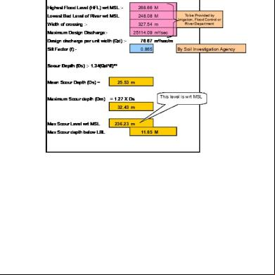
Scour Depth Calculations g2p38
December 2019 37
Black Max - Mud Motor - Operations Manual 1s1x
October 2019 110
Summer Internship Project Of Icicidirect.com On Comparative Analysis 62r2b
December 2019 125
Manufacturing Of Solar Grass Cutter 3m3k10
November 2021 0
Making Your Own Botnet D00mr4zr.pdf 3w53z
November 2019 81