Code Case 181-2 Details y6f6m
This document was ed by and they confirmed that they have the permission to share it. If you are author or own the copyright of this book, please report to us by using this report form. Report 3b7i
Overview 3e4r5l
& View Code Case 181-2 Details as PDF for free.
More details w3441
- Words: 8,011
- Pages: 41
NOTICE REGARDING CODE CASES OF THE ASME B31 CODE FOR PRESSURE PIPING
All B31 Code Cases in effect as of September 21, 2007 will remain available for use unless annulled by the B31 Standards Committee.
CASES OF THE ASME B31 CODE FOR PRESSURE PIPING
B31 Case 175 ASTM B 16 (UNS C36000) and B 453 (UNS C35300) in ASME B31.1 Construction ANNULLED Annulment Date: September 28, 2013 Reason: Requirements incorporated in ASME B31.1 Code.
B31 CASE 180 CASES OF THE CODE FOR PRESSURE PIPING – B31 B31 CASE 180 Leak Testing of Subassemblies of Jacketed Piping for use in ASME B31.3 Piping Systems Approval Date: January 5, 2007
Inquiry: Does ASME B31.3 permit an alternate leak test for jacketed piping in which it is impracticable to visually examine the welded ts and connections for leaks in accordance with para. 345.2.2(a)? Reply: Visually observing the ts and connections during the leak test in accordance with para. 345.2.2(a) and 345.3.1 is not required provided all of the following conditions are satisfied: 1. The welded ts and connections are on the inner pipe of jacketed piping. 2. A leak test is performed that otherwise meets the requirements of para. 345.1 except visual examination of ts and connection in accordance with para. 345.2.2(a) and 345.3.1 is not required. 3. A sensitive leak test is performed in accordance with para. 345.8 to demonstrate leak tightness of welded ts and connections that are not visually examined during the leak testing requirements in 2 above.
B31 Case 181‐2 (Approval Date: January 4, 2012) Use of Alternative Ultrasonic Examination Acceptance Criteria in ASME B31.3 d) Personnel demonstration requirements Original Inquiry: Under what conditions and shall be as stated in ASME Section V, limitations may alternative UT acceptance Article 4 Mandatory Appendix VII. criteria apply in lieu of those described in para. 4) Examination 344.6.2 of ASME B31.3? a) The initial straight beam scan for reflectors that could interfere with the When specified by the owner, the ultrasonic angle beam examination shall be examination acceptance criteria included below performed (a) manually, (b) as part of a may be applied for welds in material greater previous manufacturing process, or (c) than or equal to 25mm (1.0 in.) in thickness1 in during the weld examination, provided accordance with ASME B31.3 provided the detection of these reflectors is included following requirements are met: in the demonstration as required in 1(c) above. 1) General/Scope: b) The examination area shall include the a) The examination shall be conducted volume of the weld, plus the lesser of using automated or semi-automated 25mm (1.0 in.) or t of adjacent base techniques utilizing computer based data metal. Alternatively, the examination acquisition. volume may be reduced to include the b) The examination shall be performed in actual heat affected zone (HAZ) plus accordance with a written procedure 6mm (0.25 in.) of base material beyond approved by a Level III and conforming the heat affected zone on each side of to the requirements of ASME Section V, the weld, provided the extent of the Article 4 Mandatory Appendix VIII and: weld HAZ is measured and documented. i) For Phased Array – ASME Section c) Scanning may be peformed at reference V, Article 4, Mandatory Appendix level provided the procedure V qualification was performed at reference ii) For Time of Flight Diffraction level. (TOFD) - ASME Section V, Article 5) Data Recording 4, Mandatory Appendix III Data shall be recorded in the c) Procedure qualification shall meet the unprocessed form with no thresholding. requirements of ASME Section V, The data record shall include the Article 4, Mandatory Appendix IX. complete examination area as specified 2) Equipment in (4)(b) above. A mechanical guided scanner capable of maintaining a fixed and consistent search unit position relative to the weld centerline shall be used. 3) Personnel a) Set-up and scanning of welds shall be 1 For wall thicknesses less than 25mm (1.0 in.), the performed by personnel certified as acceptance criteria stated in paragraph 344.6.2 of B31.3 Level II or III (or by Level I personnel shall be used. under the direct supervision of Level II personnel). b) Interpretation and evaluation of data shall be performed by Level II or III personnel. c) Examination personnel shall be qualified and certified following a procedure or program as described in ASME BPV Code, Section V, Article 1, T-120 (e), (f), (h) and (i).
B31 Case 181‐2 (Approval Date: January 4, 2012) Use of Alternative Ultrasonic Examination Acceptance Criteria in ASME B31.3 dimension (h in Figure 1, sketch [b]) 6) Data Analysis of the subsurface indication. a) Reflectors exceeding the limits below b) Multiple Flaws shall be investigated to determine i) Discontinuous flaws that are whether the indication originates from a oriented primarily in parallel planes flaw or is a geometric indication in shall be considered to lie in a single accordance with 6(b) below. plane if the distance between the i) For amplitude based techniques, the adjacent planes is equal to or less location, amplitude, and extent of all than 13mm (0.50 in.) or 0.5t, reflectors that produce a response whichever is less. greater than 20% of the reference ii) If the space between two flaws level shall be investigated. aligned along the axis of weld is less ii) For non-amplitude based than the height of the flaw of greater techniques, the location and extent height, the two flaws shall be of all images that have an indicated considered a single flaw. length greater than 4.0mm (0.16 in.) iii) If the space between two flaws shall be investigated. aligned in the through-thickness b) Ultrasonic indications of geometric dimension is less than the height of and/or metallurgical origin shall be the flaw of greater height, the two classified as specified in ASME Section flaws shall be considered a single V, Article 4 Paragraph T-481. flaw. c) Alternatively, other techniques or NDE 8) Flaw Acceptance Criteria methods may be used to classify an indication as geometric (e.g., alternative Flaws shall be evaluated against the beam angles, radiography). The method applicable acceptance criteria of Table 1 employed is for information only to or 2, except that flaw length (l) shall not classify the indication as geometric, and exceed 4t, regardless of flaw height (h) ASME B31.3 requirements for or the calculated aspect ratio. examination techniques are only required to the extent they are applicable. 7) Flaw Evaluation a) The dimension of the flaw(s) shall be determined by the rectangle that fully contains the area of the flaw(s). (Refer to Fig. 1) i) The length, ℓ, of the flaw shall be drawn parallel to the inside pressure retaining surface of the component. ii) The height, h, of the flaw shall be drawn normal to the inside pressure retaining surface of the component. iii) The flaw shall be characterized as a surface or subsurface flaw, as shown in Figure 1. iv) A subsurface indication shall be considered as a surface flaw if the separation (S in Figure 1) of the indication from the nearest surface of the component is equal to or less than half the through wall
B31 Case 181‐2 (Approval Date: January 4, 2012) Use of Alternative Ultrasonic Examination Acceptance Criteria in ASME B31.3 TABLE 1 Acceptance Criteria for Surface Flaws Weld Thickness Aspect Ratio, h/ℓ
0.00 0.05 0.10 0.15 0.20 0.25 0.30 0.35 0.40 0.45 0.50
25mm to 64mm (1.0 in. to 2.5 in.) h/t < 0.031 < 0.033 < 0.036 < 0.041 < 0.047 < 0.055 < 0.064 < 0.074 < 0.083 < 0.085 < 0.087
100mm to 300mm (3.9 in. to 11.8 in.) h/t < 0.019 < 0.020 < 0.022 < 0.025 < 0.028 < 0.033 < 0.038 < 0.044 < 0.050 < 0.051 < 0.052
General Notes: (a) t = thickness of the weld excluding any allowable reinforcement. For a butt t ing two having different thickness at the t, t is the thinner of the two thicknesses ed. If a full penetration weld includes a fillet weld, the effective throat dimension of the fillet weld shall be included in t. (b) Aspect Ratio (h/ℓ) used may be determined by rounding the calculated h/ℓ down to the nearest 0.05 increment value within the column, or by linear interpolation. (c) For intermediate thickness t (weld thicknesses between 64mm and 100mm [2.5 in. and 3.9 in.]) linear interpolation is required to obtain h/t values.
TABLE 2 Acceptance Criteria for Subsurface Flaws Weld Thickness Aspect Ratio, h/ℓ
0.00 0.10 0.20 0.30 0.40 0.50 0.60 0.70 0.80 0.90 1.00
25mm to 64mm (1.0 in. to 2.5 in.) h/t < 0.068 < 0.076 < 0.086 < 0.098 < 0.114 < 0.132 < 0.156 < 0.180 < 0.210 < 0.246 < 0.286
100mm to 300mm (3.9 in. to 11.8 in.) h/t < 0.040 < 0.044 < 0.050 < 0.058 < 0.066 < 0.076 < 0.088 < 0.102 < 0.116 < 0.134 < 0.152
General Notes: (a) t = thickness of the weld excluding any allowable reinforcement. For a butt t ing two having different thickness at the t, t is the thinner of the two thicknesses ed. If a full penetration weld
B31 Case 181‐2 (Approval Date: January 4, 2012) Use of Alternative Ultrasonic Examination Acceptance Criteria in ASME B31.3 includes a fillet weld, the effective throat dimension of the fillet weld shall be included in t. (b) Aspect Ratio (h/ℓ) used may be determined by rounding the calculated h/ℓ down to the nearest 0.05 increment value within the column, or by linear interpolation. (c) For intermediate thickness t (weld thicknesses between 64mm and 100mm [2.5 in. and 3.9 in.]) linear interpolation is required to obtain h/t values.
h
h
S < 0.5h (a) Surface Flaw
(b) Surface Flaw
h
S > 0.5h (c) Subsurface Flaw
Figure 1: Surface and Subsurface Indications
B31 CASE 182 Use of 1.15Ni-0.65Cu-Mo-Cb in ASME B31.1 Construction
ANNULLED Annulment Date: June 1, 2015 Reason: Requirements incorporated in ASME B31.1 Code.
CASSES OF THE B31 CODE FOR PRESSURE PIPING
B31 CASE 183 -1 Use of 9Cr–2W, UNS No. K92460, in ASME B31.1 Construction Approval Date: September 25, 2013
Inquiry: May 9Cr–2W, UNS No. K92460, material conforming to one of the specifications listed in Table 1, be used for ASME B31.1 construction? Reply: It is the opinion of the Committee that 9Cr– 2W, UNS No. K92460, material conforming to one of the specifications listed in Table 1, may be used for ASME B31.1 construction provided the following additional requirements are met: (a) ASTM A369 Grade FP92 material shall not exceed a hardness of 250 HBW/265 HV (25 HRC). (b) The maximum allowable stress values for the material shall be those given in Table 2. The maximum use temperature for the material shall be 1,200°F (649°C). (c) For the purpose of procedure and performance qualifications, the material shall be considered P-No. 15E, Group 1. The procedure and performance qualifications shall be conducted in accordance with Section IX. Post-weld heat treatment for this material is mandatory, and the following rule shall apply: The PWHT requirements shall be those given for P-No. 15E, Group 1 materials in Table 132. (d) Repair welding of base material shall be permitted as prescribed by the applicable material product specification or its general requirements specification. All repair welds shall be in accordance with Section IX using one of the following processes: SMAW, SAW, GTAW, or FCAW. The composition of the welding consumables shall be such that the lower critical transformation temperature of the consumables shall exceed the maximum post weld heat treatment temperature in (c) above. If the lower critical transformation temperature is calculated rather than measured, the formula used shall be reported. If requested, data ing the validity of the formula shall be provided by the material manufacturer. All repair welds to base material shall be normalized and tempered according to the requirements of the applicable material specification. The material manufacturer shall provide a complete report of all repair welds. (e) If during the manufacturing any portion of the component is heated to a temperature greater than 1,470°F (800°C), then the component must be reaustenitized and retempered in its entirety in accordance with the applicable material specification, or that portion of the component heated above 1,470°F (800°C), including the heat-affected zone created by the local heating, must be replaced, or must be removed, reaustenitized, and retempered, and then
replaced in the component. (f) 9Cr – 2W materials subject to forming or bending
shall be heat treated in accordance with the following rules. (A) When the material is cold formed or cold bent, cold forming strains shall be calculated in accordance with para. 129.3.4.1 or 129.3.4.2. (B)If normalizing and tempering is performed, it shall not be performed locally. The pipe, tube, or component to be normalized and tempered shall either be heat treated in its entirety, or the area (including the transition to the unstrained portion) shall be cut away from the balance of the pipe, tube or component and heat treated separately or replaced. (C) If hot bending or hot forming is performed, and for all cold swages, flares or upsets, normalizing and tempering of the material is required in accordance with the requirements in the base material specification. (D) If cold bending or cold forming is performed, the material shall be heat treated as follows: (1) For materials with greater than 20% strain with design temperatures exceeding 1115°F (600°C) or for materials with greater than 25% strain with design temperatures between 1000°F (540°C) and 1115°F (600°C) inclusive, the cold strained area of the component shall be normalized and tempered in accordance with the requirements of the base material specification. (2) For materials with greater than 5% strain but less than or equal to 20% strain with design temperatures exceeding 1115°F (600°C) or with greater than 5% strain but less than or equal to 25% strain with design temperatures between 1000°F (540°C) and 1115°F (600°C) inclusive , the cold strained areas shall be heat treated at 1350-1425°F (730-775°C) for 1 hr./in. (1 hr./ 25mm.) or 30 minutes minimum. As an alternative, normalization and temper in accordance with the requirements of the base material specification may be substituted for the heat treatment required in this paragraph. (3) If only a portion of a cold bent or cold formed piping component is heated above the heat treatment temperature allowed above and the material was subjected to strains greater than 5% but less than or equal to 25% for design temperatures less than or equal to 1115°F (600°C), one of the following actions shall be performed:
(a) The component in its entirety shall be renormalized and tempered in accordance with the requirements of the base metal specification. (b) The allowable stress shall be that for Gr. 9 material (i.e., A335 P9 or equivalent product specification) at the design temperature provided that the portion of the component that was heat treated to a temperature exceeding the maximum holding temperature is subjected to a final heat treatment within the temperature range and for the time required in para. (D)(2)
above. For Boiler External Piping, the use of this provision shall be noted on the Manufacturer’s Data Report. (4) For materials with less than or equal to 5% strain or design temperatures less than 1000°F (540°C), heat treatment is neither required nor prohibited. (g) When utilized for Boiler External Piping, this Case number shall be shown on the Manufacturer’s Data Report. (h) This Case number shall be shown in the material certification and marking of the material.
TABLE 1 MATERIAL SPECIFICATIONS AND GRADES Flanges, Forged Fittings Valves and Parts ASTM A182 / A182M – 11a Grade F92 Seamless Tubes ASTM A213 / A213M – 08 Grade T92 Seamless Pipe ASTM A335 / A335M – 06 Grade P92 Forgings ASTM A336 / A336M – 10a Grade F92 Forged and Bored Pipe ASTM A369 / A369M – 06 Grade FP92 Plate ASTM A1017 / A1017M – 11 Grade 92
For Metal Temperature Not Exceeding, °F -20 to 100 200 300 400 500 600 650 700 750 800 850 900 950 1000 1050 1100 1150 1200
TABLE 2 MAXIMUM ALLOWABLE STRESS VALUES For Metal Temperature Not ksi Exceeding, °C 25.7 25.7 25.3 24.5 23.8 23.2 22.8 22.4 21.9 21.4 20.8 20.1 19.2 18.3 15.7 12.0 8.6 5.6
-30 to 40 85 100 125 150 200 250 300 325 350 375 400 425 450 475 500 525 550 575 600 625 650 [Note (1)]
MPa 177 177 177 177 174 169 165 161 159 156 154 151 148 144 140 135 129 123 99.5 77.0 56.5 38.3
GENERAL NOTE: Stress values in italics are obtained from time dependent properties NOTES: (1) The maximum use temperature is 649 °C. The value at 650 °C is provided for interpolation purposes only.
B31 CASE 185 CASES OF THE CODE FOR PRESSURE PIPING – B31
ASME B31.3 CODE CASE 185 Title: Use of Standard Helium Leak Test for a Vacuum-only Piping System (Paragraph 345) Approval Date:
December 22, 2009
Inquiry: Under what circumstances does ASME B31.3 permit the use of helium mass spectrometer leak tests performed under a vacuum as a substitute for the leak test requirements specified in ASME B31.3, para. 345? Reply: In the opinion of the Committee, the qualified helium leak tests under vacuum conditions in the ASME BPV Code, Section V, Article 10, Appendix V and Appendix IX are acceptable substitutes for the testing requirements identified in para. 345 of ASME B31.3 provided the following conditions are met: 1. The piping system is expected to operate only under vacuum (i.e., sub-atmospheric pressure) conditions. 2. Any leakage into the piping system that could result in an internal reaction (e.g., combustion or explosion) that increases the pressure above atmospheric shall be prevented. 3. All system ts and connections shall be leak tested. Piping welds and ts to be tested shall be uninsulated and exposed, and shall not be primed, painted or otherwise coated. 4. Helium leak testing is performed at vacuum conditions sufficient for the mass spectrometer helium leak tests of ASME BPV Code, Section V, Article 10, Appendices V and IX, or at pressures below 10 millibars absolute (<1% of atmospheric pressure), whichever is lower. 5. ASME B31.3, para. 345.2 applies, except for the minimum “10 min” leak test period, the leak test pressure requirements and the limitation of the need for access for jacketed piping to “visual access.” Para. 345.3 also applies, except for the leak test pressure requirements. All other inspection, examination and records requirements of ASME B31.3 Chapter VI must still be satisfied (i.e., paras. 340, 341, 342, 343, 344 and 346). 6. Written procedures shall be qualified, in accordance with BPV Code, Section V, Article 10. 7. Test personnel shall have training and certification consistent with ASME B31.3, para. 342.
Page 1 of 2
B31 CASE 185 CASES OF THE CODE FOR PRESSURE PIPING – B31
8. Test reports, including records of personnel qualifications, shall meet the requirements of ASME BPV Code, Section V, Article 10, Item T-1091 and shall be retained for at least five years. 9. Options of the ASME BPV Code, Section V, Article 10 test methods, which allow the engineering design to modify specified requirements of the Appendix V and Appendix IX test methods (such as acceptability limits for system leak tightness), may only be exercised so as to make these requirements more sensitive or more conservative. 10. The use of the vacuum leak test instead of the pressurized leak test of ASME B31.3, para. 345 shall be specified in the engineering design and shall be accepted by the Owner. ____________________________________________________________________
Page 2 of 2
B31 CASE 188 Minimum Hydrostatic Test Pressure for ASME B31.3, Chapter IX (Para. K345.4.2) ANNULLED Annulment Date: February 27, 2015 Reason: Requirements incorporated in ASME B31.3 Code.
B31 Case 189 Item 10 1605 ‐ B31 Case XXX (Draft Proposed B31.1 Code Case, 8/10/11) Use of Alternative Ultrasonic Examination Acceptance Criteria in ASME B31.1 Use of Alternative Ultrasonic Examination Acceptance Criteria in ASME B31.1 Approved: January 3, 2013 Original Inquiry: Under what conditions and limitations may alternative UT acceptance criteria apply in lieu of those described in para. 136.4.6 of ASME B31.1? When specified by the owner, the ultrasonic examination acceptance criteria included below may be applied for welds in accordance with B31.1 provided the following requirements are met: 1) General/Scope: a) The examination shall be conducted using automated or semi-automated techniques utilizing computer based data acquisition. b) The examination shall be performed in accordance with a written procedure approved by an NDE Level III and conforming to the requirements of ASME Section V, Article 4 Mandatory Appendix VIII and: i) For Phased Array – ASME Section V, Article 4, Mandatory Appendix V ii) For Time of Flight Diffraction (TOFD) - ASME Section V, Article 4, Mandatory Appendix III c) Procedure qualification shall meet the requirements of ASME Section V, Article 4, Mandatory Appendix IX. 2) Equipment a) A mechanical guided scanner capable of maintaining a fixed and consistent search unit position relative to the weld centerline shall be used. 3) Personnel a) Set-up and scanning of welds shall be performed by personnel certified as NDE Level II or III (or by Level I personnel under the direct supervision of Level II or Level III personnel). b) Interpretation and evaluation of data shall be performed by NDE Level II or III personnel. c) Examination personnel shall be qualified and certified following a procedure or program as described in
BPV Code, Section V, Article 1, T-120 (e), (f), (h) or (i). d) Personnel demonstration requirements shall be as stated in ASME Section V, Article 4 Mandatory Appendix VIII and all additional Owner stipulated demonstration requirements. 4) Examination a) The initial straight beam scan for reflectors that could interfere with the angle beam examination shall be performed (a) manually, (b) as part of a previous manufacturing process, or (c) during the weld examination, provided detection of these reflectors is included in the demonstration as required in 1(c) above. b) The examination area shall include the volume of the weld, plus the lesser of 25mm (1.0 in.) or t of adjacent base metal. Alternatively, the examination volume may be reduced to include the actual heat affected zone (HAZ) plus 6mm (0.25 in.) of base material beyond the heat affected zone on each side of the weld, provided the extent of the weld HAZ is measured and documented. c) Scanning may be peformed at reference level provided the procedure qualification was performed at reference level. 5) Data Recording Data shall be recorded in the unprocessed form with no thresholding. The data record shall include the complete examination area as specified in (4)(b) above. 6) Data Analysis a) Reflectors exceeding the limits below shall be investigated to determine whether the indication originates from a discontinuity or is a geometric indication in accordance with 6(b) below. i) For amplitude based techniques, the location, amplitude, and extent of all reflectors that produce a response
Item 10 1605 ‐ B31 Case XXX (Draft Proposed B31.1 Code Case, 8/10/11) Use of Alternative Ultrasonic Examination Acceptance Criteria in ASME B31.1 shall be considered to lie in a single greater than 20% of the reference plane if the distance between the level shall be evaluated. adjacent planes is equal to or less ii) For non-amplitude based than 13mm (0.50 in.) or 0.5t, techniques, the location and extent whichever is less. of all images that have an indicated ii) If the space between two indications length greater than 4.0mm (0.16 in.) aligned along the axis of weld is less shall be investigated. than the height of the indication of b) Ultrasonic indications of geometric greater height, the two and/or metallurgical origin shall be discontinuities shall be considered a classified as specified in ASME Section single discontinuity. V, Article 4 Paragraph T-481. iii) If the space between two indication i) Alternatively, other techniques or aligned in the through-thickness NDE methods may be used to dimension is less than the height of classify an indication as geometric the indication of greater height, the (e.g., alternative beam angles, two indications shall be considered radiography). The method employed a single discontinuity. is for information only to classify 8) Discontinuity Acceptance Criteria the indication as geometric, and Discontinuities shall be evaluated using ASME B31.1 requirements for the applicable criteria of Table 1, 2, or 3, examination techniques are only with the following additional required to the extent they are requirement: applicable. 7) Discontinuity Evaluation a) Regardless of discontinuity height or aspect ratio, discontinuity length shall a) The dimension of the discontinuity(s) not exceed 4t. shall be determined by the rectangle that 9) Documentation fully contains the area of the discontinuity(s). (Refer to Fig. 1) a) This Case number shall be i) The length, ℓ, of the discontinuity referenced in the documentation and shall be drawn parallel to the inside marking of the material and pressure retaining surface of the recorded on the Manufacturer's Data component. Report, as applicable. ii) The height, h, of the discontinuity shall be drawn normal to the inside pressure retaining surface of the component. iii) The discontinuity shall be characterized as a surface or subsurface discontinuity, as shown in Figure 1. iv) A subsurface indication shall be considered as a surface discontinuity if the separation (S in Figure 1) of the indication from the nearest surface of the component is equal to or less than half the through wall dimension (h in Figure 1, sketch [b]) of the subsurface indication. b) Multiple Discontinuities i) Discontinuous indications that are oriented primarily in parallel planes
Item 10 1605 ‐ B31 Case XXX (Draft Proposed B31.1 Code Case, 8/10/11) Use of Alternative Ultrasonic Examination Acceptance Criteria in ASME B31.1 TABLE 1 Discontinuity Acceptance Criteria for Weld Thickness <25mm (1.0 in.) h/t ℓ Surface discontinuity < 0.100 < 6.4 mm (0.25 in.) Subsurface discontinuity < 0.286 < 6.4 mm (0.25 in.) GENERAL NOTES: (a) t = thickness of the weld excluding any allowable reinforcement. For a butt t ing two having different thickness at the t, t is the thinner of the two thicknesses ed. If a full penetration weld includes a fillet weld, the effective throat dimension of the fillet weld shall be included in t. (b) A discontinuity is considered rejectable if its dimensions exceed the h/t value or the ℓ value in the Table above.
Item 10 1605 ‐ B31 Case XXX (Draft Proposed B31.1 Code Case, 8/10/11) Use of Alternative Ultrasonic Examination Acceptance Criteria in ASME B31.1
TABLE 2 Surface Discontinuity Acceptance Criteria for Weld Thickness > 25mm (1.0in.) Weld Thickness h/ℓ
> 25mm to 64mm (1.0 in. to 2.5 in.)
h/t
h/t
0.00 0.05 0.10 0.15 0.20 0.25 0.30 0.35 0.40 0.45 0.50
< 0.031 < 0.033 < 0.036 < 0.041 < 0.047 < 0.055 < 0.064 < 0.074 < 0.083 < 0.085 < 0.087
< 0.019 < 0.020 < 0.022 < 0.025 < 0.028 < 0.033 < 0.038 < 0.044 < 0.050 < 0.051 < 0.052
Aspect Ratio,
> 64mm to < 100mm (2.5 in. to 3.9 in.)
(See Note C)
100mm to 300mm (3.9 in. to 11.8 in.)
General Notes: (a) t = thickness of the weld excluding any allowable reinforcement. For a butt t ing two having different thickness at the t, t is the thinner of the two thicknesses ed. If a full penetration weld includes a fillet weld, the effective throat dimension of the fillet weld shall be included in t. (b) Aspect Ratio (h/ℓ) used may be determined by rounding the calculated h/ℓ down to the nearest 0.05 increment value within the column, or by linear interpolation.
(c) Regardless of discontinuity height or aspect ratio, discontinuity length shall not exceed 4t. (d) For intermediate thickness t (weld thicknesses between 64mm and 100mm [2.5 in. and 3.9 in.]) linear interpolation is required to obtain h/t values.
Item 10 1605 ‐ B31 Case XXX (Draft Proposed B31.1 Code Case, 8/10/11) Use of Alternative Ultrasonic Examination Acceptance Criteria in ASME B31.1
TABLE 3 Subsurface Discontinuity Acceptance Criteria for Weld Thickness > 25mm (1.0in.) Weld Thickness Aspect Ratio, h/ℓ
0.00 0.10 0.20 0.30 0.40 0.50 0.60 0.70 0.80 0.90 1.00
> 25mm to 64mm (1.0 in. to 2.5 in.) h/t < 0.068 < 0.076 < 0.086 < 0.098 < 0.114 < 0.132 < 0.156 < 0.180 < 0.210 < 0.246 < 0.286
> 64mm to < 100mm (2.5 in. to 3.9 in.)
(See Note C)
100mm to 300mm (3.9 in. to 11.8 in.) h/t < 0.040 < 0.044 < 0.050 < 0.058 < 0.066 < 0.076 < 0.088 < 0.102 < 0.116 < 0.134 < 0.152
General Notes:
(a) t = thickness of the weld excluding any allowable reinforcement. For a butt t ing two having different thickness at the t, t is the thinner of the two thicknesses ed. If a full penetration weld includes a fillet weld, the effective throat dimension of the fillet weld shall be included in t. b) Aspect Ratio (h/ℓ) used may be determined by rounding the calculated h/ℓ down to the nearest 0.05 increment value within the column, or by linear interpolation. c) Regardless of discontinuity height or aspect ratio, discontinuity length shall not exceed 4t. d) For intermediate thickness t (weld thicknesses between 64mm and 100mm [2.5 in. and 3.9 in.]) linear interpolation is required to obtain h/t values.
Item 10 1605 ‐ B31 Case XXX (Draft Proposed B31.1 Code Case, 8/10/11) Use of Alternative Ultrasonic Examination Acceptance Criteria in ASME B31.1
h
h
S < 0.5h (a) Surface Discontinuity
(b) Surface Discontinuity (see para. 7(a) (iv.)
h
S > 0.5h (c) Subsurface Discontinuity
Figure 1: Surface and Subsurface Indications
B31 Case 190 Seamless Ni-25Cr-20 Co Material Use in B31.1 Approval Date: November 12, 2012 Inquiry: May precipitation-hardenable Ni-25Cr-20Co alloy (UNS N07740) wrought sheet, plate, rod, seamless pipe and tube, fittings and forgings material conforming to the chemical requirements shown in Table 1, the mechanical properties listed in Table 2, and otherwise conforming to the applicable requirements in the specifications listed in Table 3 and in this Case be used in welded construction under ASME B31.1 rules? Reply: It is the opinion of the committee that precipitation-hardenable Ni-25Cr-20Co alloy (UNS N07740) wrought sheet, plate rod, seamless pipe and tube, fittings and forgings as described in the Inquiry may be used in welded construction complying with the rules of ASME B31.1, provided the following rules are met: (a) Material shall be supplied in the solution heat treated and aged condition. Solution heat treatment shall be performed at 2010°F (1100°C) minimum for 1 hour per inch (25 mm) of thickness but not less than ½ hr. Aging shall be performed at 1400°F to 1500°F (760°C to 816°C) for 4 hours minimum up to 2 inches (50 mm) of thickness, plus an additional ½ hour per additional inch (25 mm) of thickness. Aging shall be followed by air cooling. (b) The maximum allowable stress values for the material shall be those given in Tables 4 and 4M. (c) Separate weld procedure and performance qualifications shall be required. Qualifications shall be performed with material that is first annealed and aged in accordance with (a) above. Welding shall be limited to either solid bare wire GTAW and/or GMAW processes. When welding this alloy to itself, the weld metal shall be of matching chemical composition. The welding procedure qualification shall be conducted as prescribed in Section IX except that the guided bend test required by QW-160 may use a 4T minimum bend radius. (d) Postweld heat treatment for this material is mandatory. The postweld heat treatment shall be performed at 1400°F – 1500°F (760°C – 815°C) for a minimum of 4 hours for thickness up to 2 inches (50 mm), plus an additional 1 hour per additional inch (25 mm) of thickness. If a longitudinal weld seam is required in the construction of a component, a weld strength reduction factor of 0.70 shall apply in accordance with rules in para. and Table 102.4.7 for applications at temperatures above 1112°F (600°C). (e) After cold forming to strains in excess of 5%; after any swages, upsets, or flares; or after any hot forming of this material, the component shall be heat treated in accordance with the requirements specified in (a) above. No local solution annealing may be performed. The entire affected component or part that includes the cold strained area and transition to unstrained material must be included in both heat treatments. Forming strains shall be calculated as listed in ASME- B31.1 2012 Edition paragraph 129.3.4.1
When forming strains cannot be calculated as noted above, the manufacturer shall have the responsibility to determine the maximum forming strain. (f) The maximum use temperature is 1472°F (800°C). (g) For the temperature-dependent parameter, y, as noted in Table 104.1.2(A) shall be as follows; (1) 1150°F (621°C) and below: 0.4 (2) 1200°F (649°C): 0.5 (3) above 1200°F (649°C): 0.7 (h) External pressure design is prohibited. (i) This Case number shall appear in the marking and certification for the material and on the Manufacturer’s Data Report. TABLE 1 CHEMICAL REQUIREMENTS Element Chemical Composition Limits, % Chromium 23.5 – 25.5 Cobalt 15.0 – 22.0 Aluminum 0.2 – 2.0 Titanium 0.5 – 2.5 Columbium+Tantalum 0.50 – 2.5 Iron 3.0 max Carbon 0.005 – 0.08 Manganese 1.0 max Molybdenum 2.0 max Silicon 1.0 max Copper 0.50 max Phosphorous 0.03 max Sulfur 0.03 max Boron 0.0006 – 0.006 Nickel remainder
TABLE 2 MECHANICAL PROPERTIES REQUIREMENTS Tensile strength, min., ksi (MPa) 150 (1035) Yield strength, min., ksi (MPa) 90 (620) Elongation in 2 in., min., % 20
TABLE 3 SPECIFICATION Seamless Pipe and Tube Plate, sheet and strip Bar Forgings Wrought fittings
SB-622 SB-435 SB-572 SB-564 SB-366
TABLE 4 MAXIMUM ALLOWABLE STRESS VALUES For Metal Temperature Stress Values, ksi [Note (1)] Not Exceeding, °F -20 to 100 42.9 200 42.9 300 42.9 400 42.6 500 41.1 600 40.3 650 40.1 700 40.0 750 40.0 800 40.0 850 40.0 900 40.0 950 40.0 1000 40.0 1050 40.0 1100 39.8 1150 39.1 1200 33.1 1250 26.2 1300 20.2 1350 15.1 1400 10.7 1450 6.9 1500 3.2 [Note (2)] NOTES: (1) Stress values shown in italics are obtained from timedependent properties. (2) The maximum use temperature shall be 1472ºF. Datum for 1500ºF temperature is provided for interpolation purposes.
TABLE 4M MAXIMUM ALLOWABLE STRESS VALUES Stress For Metal Temperature Values, MPa [Note (1)] Not Exceeding, °C -30 to 40 295 65 295 100 295 150 295 200 294 250 285 300 279 325 277 350 276 375 276 400 276 425 276 450 276 475 276 500 276 525 276 550 276 575 276 600 274 625 269 650 226 675 183 700 146 725 113 750 84.1 775 59.1 800 34.5 NOTE: (1) Stress values shown in italics are obtained from timedependent properties.
B31 Code Case 191 Cu-13Zn-1.1Ni-Si-Al Alloy Seamless Pipe and Tube ASME B31.3 Approval Date: January 21, 2015
Inquiry: May precipitation-hardened (Temper Designation TF00) Cu-13Zn-1.1Ni-Si-Al alloy (UNS No. C69100) seamless pipe and tube conforming to the requirements of ASTM B706-00 (R2011) be used under the rules of ASME B31.3?
Reply: Yes, provided:
(a) The maximum allowable stress values for the material shall be those given in
Table 1; (b) Welded and brazed construction is not permitted; (c) The maximum use temperature shall be 204ºC (400ºF);
(d) Certification to the ASTM B706-00 (R2011) specification requirements shall be
mandatory.
Table 1 Maximum Allowable Stress Values
For Metal Temperature Not Stress, ksi Exceeding, °F 100 150 200 250 300 350 400
20.0 20.0 20.0 20.0 20.0 19.9 19.5
For Metal Temperature Not Exceeding, °C
40 65 100 125 150 175 200 225
Stress, MPa 138 138 138 138 138 137 135 132
Note: The maximum use temperature for this alloy is 204ºC (400ºF). The value listed at 225ºC is provided for interpolation purposes only.
B31 Case 192-1 Approval Date: September 3, 2015 Cu-13Zn-1.1Ni-Si-AI Alloy Seamless Pipe and Tubing ASME B31.1 Inquiry: May precipitation-hardened Cu-13Zn-1.1Ni-Si-Al alloy (UNS No. C69100), seamless pipe and tubing conforming to the requirements of ASTM B706-00 (reapproved 2011) be used for nonwelded construction under the rules of ASME B31.1? Reply: It is the opinion of the Committee that precipitation-hardened Cu-13Zn-1.1Ni-Si-Al alloy (UNS No. C69100), seamless pipe and tubing conforming to the requirements of ASTM B706-00 may be used for non-welded construction under the rules of ASME B31.1, provided the following additional requirements are met: (a) The tubing shall be in the precipitation-hardened condition; temper TF00 in B706. (b) The maximum allowable stress values for the material shall be those given in Table 1. The maximum design temperature shall be 400ºF (204ºC). (c) This Case number shall be referenced in the documentation and marking of the material and shown on the Manufacturer’s Data Report.
Table 1 Maximum Allowable Stress Values For Metal Temperature Not Exceeding, °F 100 150 200 250 300 350 400
Stress, ksi 17.1 17.1 17.1 17.1 17.1 17.1 17.1
For Metal Temperature Not Exceeding, °C 40 65 100 125 150 175 200 225
Stress, MPa 118 118 118 118 118 118 118 117
Note: The maximum use temperature for this alloy is 400°F (204°C); the value listed at 225°C is provided for interpolation purposes only.
TABLE 1 MAXIMUM ALLOWABLE STRESS VALUES (U. S. Customary) For Metal Temperature Not Exceeding, °F 100 200 300 400 500 600 650
Stress Values, ksi Sheet and Strip ≤0.187 in. 28.6 27.7 26.1 25.8 25.8 25.8 25.8
Plate >0.187 in.
Tube Pipe
27.1 26.3 24.8 24.5 24.5 24.5 24.5
28.6 27.7 26.1 25.8 25.8 25.8 25.8
27.1 26.3 24.8 24.5 24.5 24.5 24.5
TABLE 1M MAXIMUM ALLOWABLE STRESS VALUES (Metric) For Metal Temperature Not Exceeding, °C
Stress Values, MPa Sheet and Strip ≤5 mm
40 65 100 150 200 250 300 325 350 [Note (1)]
197 197 189 180 178 178 178 178 178
Plate >5 mm 187 187 180 171 169 169 169 169 169
Tube Pipe 197 197 189 180 178 178 178 178 178
187 187 180 171 169 169 169 169 169
NOTES: (1) The value at 350°C is for interpolation only. The maximum use temperature is 343°C. Precautionary Note: This material may be expected to develop embrittlement after exposure at moderately elevated temperatures. See ASME Boiler and Pressure Vessel Code, Section II, Part D, Nonmandatory Appendix A, Paragraph A-211 Thermal Aging Embrittlement.
Case 193 Approval Date: October 9, 2014 Cu-5.5Zn-4Si Casting Alloy UNS No. C87600 ASME B31.3 Inquiry: May Cu-5.5Zn-4Si Casting Alloy UNS No. C87600 conforming to the requirements of ASTM B584 be used for construction under the rules of ASME B31.3? Reply: Yes, provided: (a) The basic allowable stress values for the material shall be those given in Table 1.
A Casting Quality Factor, Ec, needs to be applied; (b) The maximum use temperature shall be 177ºC (350ºF); (c) Separate weld procedure and performance qualifications shall apply to this
material. The welding procedure qualifications shall be in accordance with ASME Section IX.
Table 1 Basic Allowable Stress Values For Metal Temperature Not Exceeding, °F 100 150 200 250 300 350
Stress, ksi 20.0 20.0 20.0 20.0 20.0 20.0
For Metal Temperature Not Exceeding, °C 40 65 100 125 150 175 200
Stress, MPa 138 138 138 138 138 138 137
Note: The maximum use temperature for this alloy is 177ºC (350ºF): The value listed at 200ºC is provided for interpolation purposes only.
B31 Case 194 Approval Date: December 2, 2014 ASTM B584 (UNS No. C87600) in ASME B31.1 Construction ASME B31.1 Inquiry: May silicon bronze alloy UNS No. C87600 casting to ASTM B584 be used for ASME B31.1 Construction? Reply: Yes, provided the following requirements are met: (a) This material shall not be used for boiler external piping except where specifically permitted by ASME B&PV I. See Para. 100.1.2(A) (b) The maximum permissible design temperature shall not exceed 149ºC (300ºF). (c) Limitations for use of this material for flammable liquids and gases shall be in accordance with paragraphs 122.7, 122.8 and 124.7. (d) The allowable stress values are shown in Table 1. (e) This Case number shall be referenced in the documentation and marking of the material.
Table 1 Maximum Allowable Stress Values For Metal Temperature Not Exceeding, °F 100 150 200 250 300
Stress, ksi 13.7 13.7 13.7 13.7 13.7
For Metal Temperature Not Exceeding, °C 40 65 100 125 150
Stress, MPa 94.6 94.6 94.6 94.6 94.6
Note: The maximum use temperature for this alloy is 149ºC (300ºF): The value listed at 150ºC is provided for interpolation purposes only. General Note: The casting quality factor of 0.8 is included in the allowable stress value in Table 1.
B31 Case 195 Approval Date: July 23, 2014 Use of UNS S32003 Stainless Steel for ASME ASME B31.1 Inquiry: May ferritic/austenitic duplex stainless steel UNS No. S32003 seamless and welded pipe and tube, and plate, sheet and strip conforming to the requirements of ASTM A240, A789 and A790 as applicable, be used in ASME B31.1 construction? Reply: It is the opinion of the Committee that the materials described in the Inquiry may be used in ASME B31.1 construction provided that all applicable requirements of ASME B31.1 and the following additional requirements are met: (a) This material shall not be used for Boiler External Piping. See para. 100.1.2 (A). (b) The design temperature shall not exceed 650°F (343°C). (c) The maximum allowable design stress values shall be those listed in Tables 1 or 1M. For welded pipe and tube, a t efficiency factor of 0.85 shall be used. (d) Welding procedure and performance qualifications shall be performed in accordance with Section IX of the ASME Boiler and Pressure Vessel Code. The material shall be considered as P-No. 10H. (e) Heat treatment after welding is neither required nor prohibited. However, if heat treatment is applied, the solution annealed heat treatment shall be as noted in the corresponding specification. (f) This Case number shall be included in the material documentation and marking of the material.
TABLE 1 MAXIMUM ALLOWABLE STRESS VALUES (U. S. Customary) For Metal Temperature Not Exceeding, °F 100 200 300 400 500 600 650
Stress Values, ksi Sheet and Strip ≤0.187 in. 28.6 27.7 26.1 25.8 25.8 25.8 25.8
Plate >0.187 in.
Tube Pipe
27.1 26.3 24.8 24.5 24.5 24.5 24.5
28.6 27.7 26.1 25.8 25.8 25.8 25.8
27.1 26.3 24.8 24.5 24.5 24.5 24.5
TABLE 1M MAXIMUM ALLOWABLE STRESS VALUES (Metric) For Metal Temperature Not Exceeding, °C
Stress Values, MPa Sheet and Strip ≤5 mm
40 65 100 150 200 250 300 325 350 [Note (1)]
197 197 189 180 178 178 178 178 178
Plate >5 mm 187 187 180 171 169 169 169 169 169
Tube Pipe 197 197 189 180 178 178 178 178 178
187 187 180 171 169 169 169 169 169
NOTES: (1) The value at 350°C is for interpolation only. The maximum use temperature is 343°C. Precautionary Note: This material may be expected to develop embrittlement after exposure at moderately elevated temperatures. See ASME Boiler and Pressure Vessel Code, Section II, Part D, Nonmandatory Appendix A, Paragraph A-211 Thermal Aging Embrittlement.
Case 196 Approval Date: May 15, 2015 Ductile Iron Casting UNS No. F33100 ASME B31.3 Inquiry: May Ductile Iron Castings UNS No. F33100 conforming to the requirements of ASTM A536, Grade 65-45-12 be used for construction under the rules of ASME B31.3? Reply: Yes, provided: (a) The maximum allowable stress values for the material shall be those given in Table 1; (b) A casting quality factor, Ec, of 0.80 shall also be applied, except as permitted in (c); (c) The casting quality factor may be increased by performing supplementary examination(s) listed in Table 302.3.3(c). The casting shall have first been visually examined as required by MSS SP-55, Quality Standard for Steel Castings for Valves, Flanges and Fittings and other Piping Components – Visual Method; (d) The maximum use temperature shall be 260ºC (500°F); (e) The minimum use temperature shall be -30°C (-20°F); (f) All other requirements of ASME B31.3 shall be followed. Table 1 – Maximum Allowable Stress Values For Metal Temperature Not Exceeding, °C 40 65 100 125 150 175 200 225 250 275
Stress, MPa 149 149 149 149 149 149 148 148 148 147
For Metal Temperature Not Exceeding, °F 100 150 200 250 300 350 400 450 500
Stress, ksi 21.7
21.7 21.7 21.7 21.7 21.7 21.7 21.7 21.6
Note: The maximum use temperature for this alloy is 260ºC (500º·F). The value listed at 275ºC is provided for interpolation purposes only.
B31 Case 197 Approval Date: September 3, 2015 Grade 1 Ni-Cr-Mo-Cb alloy (UNS N06625) ASME B31.1 Inquiry: May annealed Grade 1 Ni-Cr-Mo-Cb alloy (UNS N06625) seamless pipe and tube (SB-444); welded pipe (SB-705); welded tube (SB-704); plate, sheet, strip (SB-443); rod and bar (SB-446); and forgings (SB-564) be used in water wetted Boiler External Piping (BEP) welded construction for temperatures up to 1100°F (593°C). Reply: Yes, providing the following requirements are met: (a) The maximum allowable stress shall be as listed in Tables 1 and 1M and Tables 2 and 2M. (b) Welding procedures and performance qualifications shall be conducted as prescribed in ASME Section IX. (c) The value of y for this material [see Table 104.1.2(A)] shall be 0.4 for all temperatures. (d) For plate, sheet, strip, bar and forgings, the minimum tensile strength of reduced tension specimens in accordance with QW-462.1 of ASME Section IX shall not be less than 110,000 psi (758 MPa) (e) All other requirements of ASME B31.1 shall be followed. (f) When utilized for Boiler External Piping, this Case number shall be shown on the Manufacturer’s Data Report. (g) This Case number shall be shown in the material certification and marking of the material. NOTE: Alloy UNS N06625 is subject to severe loss of impact strength at room temperature after exposure in the range of 1000°F to 1400°F (538°C to 760°C). CAUTIONARY NOTE: Austenitic alloys are subject to stress corrosion cracking, intergranular attack, pitting and crevice corrosion when used in boiler applications in aqueous environments. Factors that affect the susceptibility of these materials are applied or residual stress, water chemistry and deposition of solids, and material condition. Susceptibility to attack is enhanced when the material is used in a sensitized condition or with residual cold work. Concentration of corrosive agents (e.g., chlorides, caustic, or reduced sulfur species) can occur under deposits formed on the surface of these materials, and can result in severe underdeposit wastage or cracking. For successful operation in water environments, careful attention must be paid to continuous control of water chemistry.
TABLE 1 MAXIMUM ALLOWABLE STRESS VALUES FOR SEAMLESS PIPE AND TUBE, PLATE, SHEET, STRIP, BARS, RODS, SHAPES AND FORGINGS
For Metal Temperature Not Exceeding,° F -20 to 100 200 300 400 500 600 650 700 750 800 850 900 950 1000 1050 1100
Values, ksi 34.3 34.3 34.3 33.6 32.9 32.4 32.1 31.8 31.5 31.2 30.9 30.6 30.3 29.9 29.5 29.0
TABLE 1M MAXIMUM ALLOWABLE STRESS VALUES FOR SEAMLESS PIPE AND TUBE, PLATE, SHEET, STRIP, BARS, RODS, SHAPES AND FORGINGS
For Metal Temperature Not Exceeding, °C -30 to 40 65 100 125 150 175 200 225 250 275 300 325 350 375 400 425 450 475 500 525 550 575 600 [Note1]
Values, MPa 236 236 236 236 236 234 232 230 228 226 224 222 221 219 217 215 213 212 210 207 205 202 192
Note 1: The value at 600°C is given for interpolation only; the maximum use temperature is 593°C
TABLE 2 MAXIMUM ALLOWABLE STRESS VALUES FOR WELDED PIPE AND TUBE For Metal Temperature Not Exceeding, °F Values, ksi -20 to 100 29.1 200 29.1 300 29.1 400 28.5 500 28.0 600 27.5 650 27.3 700 27.0 750 26.8 800 26.5 850 26.3 900 26.0 950 25.7 1000 25.4 1050 25.1 1100 24.7
TABLE 2M MAXIMUM ALLOWABLE STRESS VALUES FOR WELDED PIPE AND TUBE For Metal Temperature Not Exceeding, °C Values, MPa -30 to 40 201 65 201 100 201 125 201 150 201 175 199 200 197 225 196 250 194 275 192 300 190 325 189 350 188 375 186 400 184 425 183 450 181 475 180 500 179 525 176 550 174 575 172 600 [Note 1] 163 Note 1: The value at 600°C is given for
interpolation only; the maximum use temperature is 593°C
Related Documents 3m3m1z
Code Case 181-2 Details y6f6m
December 2019 28
Code Case 9454b
October 2020 0
Sbbj New Branch Code Details 5yt4p
December 2019 167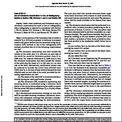
Code Case 2235-10 2qb3s
December 2021 0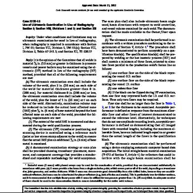
Code Case - 2235-10 285v7
November 2021 0
Code Case 181 2m3t4a
December 2019 15More Documents from "Eswaran" 2n2y4q

Special Electrical Machines 256t5p
December 2019 41
Ge Approved Vendor List.pdf 3vqf
November 2019 181
Dbs Credit Limit Review Consent Form(p.e.t) 1h2b25
October 2021 0
Lux Meter.pdf 4a5u1r
October 2021 0
Pcn Renewal Forms Regulation .pdf 2z2y3v
November 2019 44