Comparison Between Edge And Screw Dislocation.docx l3g6m
This document was ed by and they confirmed that they have the permission to share it. If you are author or own the copyright of this book, please report to us by using this report form. Report 3b7i
Overview 3e4r5l
& View Comparison Between Edge And Screw Dislocation.docx as PDF for free.
More details w3441
- Words: 1,616
- Pages: 5
Comparison between edge and screw dislocation S. NO
Edge dislocation
Screw dislocation
1
These dislocations arise due to introduction or elimination of an extra row of atoms.
2
Tensile, compressive and shear stress fields may be present. Region of lattice disturbance extends along an dislocation line.
A screw dislocation provides for easy crystal growth because additional atoms and unit cells can be added to step of the screw. Only shear stress field exists.
3
4 5
6
Burger’s vector is always perpendicular to the dislocation line These dislocation are formed during deformation and during crystallisation. An edge dislocation (pure) can glide and climb
Region of lattice disturbance extends in two separate planes at right angles to each other. Burger’s vector is parallel to the dislocation line. These dislocations are also formed during deformation and during crystallisation. A screw dislocation can glide only.
LINE DEFECTS Line imperfections are called dislocations. A linear disturbance of the atomic arrangement, which can move very easily on the slip plane through the crystal, is known as dislocation. The dislocation may be caused during growth of crystals from a melt or form a vapor or they may occur during a slip.
The defect which takes place due to dislocation of atoms along a line in same direction is called line defects. The line defects also takes place when a central portion of a crystal lattice slips without affecting the outer portion. These are two types of line defects: a. Edge Dislocation b. Screw Dislocation. Both these defects are the most striking imperfections and are responsible for the useful property of ductility in metals, ceramics and crystalline polymers. Whenever the atoms are displaced in two separate planes perpendicular to each other then the defect so produced is known as screw dislocation. Fig a: represents an isometric view of a perfect crystal. Fig b: shows the displacement of atoms appear like that of a screw or helical surfaces.
In this type of dislocation shear stresses are associated with adjacent atoms and extra energy is involved, along the dislocation. The successive atom planes are transformed into the surface of the helix of screw by this dislocation which s for its name as screw dislocation. A screw dislocation has its displacement of Burger's vector parallel to the linear defect but there is distortion of the plane. Edge Dislocation An edge dislocation may be described as an extra plane of atoms within a crystal structure. It is accompanied by zones of compression and of tension so that there is a net increase in energy along a dislocation. The displacement distance for atoms around the dislocation is called 'burger's vector'. This vector is at right angle to the edge dislocation.
Whenever a half plane of atom is inserted between the planes of atoms in a perfect crystals then this defect is produced Fig a: Shows a cross section of a crystal where dots represent atoms arranged in an orderly manner. Fig b: Shows the displacement of atoms when an extra half plane is inserted from the top. It may be noted from this Fig that top and bottom of the crystal above and below the line X-Y appears perfect.
If the extra half plane is inserted from top the defect so produced is represented by ┴ [inverted T] as shown in Fig. and if the extra half plane is inserted from the bottom, the defect so produced is represented by T. The criterion of distortion is what is called the burgers vector. It can be determined if a closed contour is drawn around a zone in an ideal crystal by ing from one site to another as shown in Fig. (a) and then the procedure is repeated a zone in a real crystal containing a dislocation. As may be seen from Fig. (b), the contour described in real crystal turns out to be unclosed. The vector required for the closing the contour is the Burgers vector. The Burger's vector of an edge dislocation is equal to the inter atomic space and perpendicular to the dislocation line.
Surface Defects:These are two dimensional imperfections that lies in the metal with polycrystalline structures or they are also called as interfacial defects can be defined as boundaries that have two dimensional imperfections in crystalline solids, and have different crystal structures and/or crystallographic orientations on either side of them. They refer to the regions of distortions that lie about a surface having thickness of a few atomic diameters. For example: external surfaces, grain boundaries, twin boundaries, stacking faults, and phase boundaries. These imperfections are not thermodynamically stable, rather they are meta-stable imperfections. They arise from the clustering of line defects into a plane. External surface: The environment of an atom at a surface differs from that of an atom in the bulk; especially the number of neighbors (coordination) at surface is less. Thus the unsaturated bonds of surface atoms give rise to a surface energy. This result in relaxation (the lattice spacing is decreased) or reconstruction (the crystal structure changes). To reduce the energy, materials tend to minimize, if possible, the total surface area. Grain boundaries: Crystalline solids are, usually, made of number of grains separated by grain boundaries. Grain boundaries are several atoms distances wide, and there is mismatch of orientation of grains on either side of the boundary as shown in figure-3.6. When this misalignment is slight, on the order of few degrees (<
10°), it is called low angle grain boundary. These boundaries can be described in of aligned dislocation arrays. If the low grain boundary is formed by edge dislocations, it is called tilt boundary, and twist boundary if formed of screw dislocations. Both tilt and twist boundaries are planar surface imperfections in contrast to high angle grain boundaries. For high angle grain boundaries, degree of disorientation is of large range (> 15°). Grain boundaries are chemically more reactive because of grain boundary energy. In spite of disordered orientation of atoms at grain boundaries, polycrystalline solids are still very strong as cohesive forces present within and across the boundary.
Twin boundaries: It is a special type of grain boundary across which there is specific mirror lattice symmetry. Twin boundaries occur in pairs such that the orientation change introduced by one boundary is restored by the other (figure-). The region between the pair of boundaries is called the twinned region. Twins which forms during the process of recrystallization are called annealing twins, whereas deformation twins form during plastic deformation. Twinning occurs on a definite crystallographic plane and in a specific direction, both of which depend on the crystal structure. Annealing twins are typically found in metals that have FCC crystal structure (and low stacking fault energy), while mechanical/deformation twins are observed in BCC and H metals. Annealing twins are usually broader and with straighter sides than mechanical twins. Twins do not extend beyond a grain boundary.
Stacking faults: They are faults in stacking sequence of atom planes. Stacking sequence in an FCC crystal is ABC ABC ABC …, and the sequence for H crystals is AB AB AB…. When there is disturbance in the stacking sequence, formation of stacking faults takes place. Two kinds of stacking faults in FCC crystals are: (a) ABC AC ABC…where CA CA represent thin H region which is nothing but stacking fault in FCC, (b) ABC ACB CABC is called extrinsic or twin stacking fault. Three layers ACB constitute the twin. Thus stacking faults in FCC crystal can also be considered as submicroscopic twins. This is why no microscopic twins appear in FCC crystals as formation of stacking faults is energetically favorable. Stacking fault energy varies in range 0.01-0.1 J/m2. Lower the stacking fault energy, wider the stacking fault, metal strain hardens
rapidly and twin easily. Otherwise, metals of high stacking fault energy i.e. narrower stacking faults show a deformation structure of banded, linear arrays of dislocations. Phase boundaries exist in multiphase materials across which there is sudden change in physical/chemical characteristics. The top and bottom faces of the unit cell consist of six atoms that form regular hexagons and surround a single atom in the center. Another plane that provides three additional atoms to the unit cell is situated between the top and bottom planes. The atoms in this mid-plane have as nearest neighbors atoms in both of the adjacent two planes. The equivalent of six atoms is contained in each unit cell; one-sixth of each of the 12 top and bottom face corner atoms, one-half of each of the 2 center face atoms, and all 3 mid-plane interior atoms. If a and c represent, respectively, the short( basal) and long 9 height) parameters of unit cell dimensions of Fig a, the c/a ratio should be 1.633 . The coordination number and the atomic packing factor for the H crystal structure are the same as for FCC: 12 and 0.74, respectively
Volume defects: as name suggests are defects in 3-dimensions. These include pores, cracks, foreign inclusions and other phases. These defects are normally introduced during processing and fabrication steps. All these defects are capable of acting as stress raisers, and thus deleterious to parent metal’s mechanical behaviour. However, in some cases foreign particles are added purposefully to strengthen the parent material. The procedure is called dispersion hardening where foreign particles act as obstacles to movement of dislocations, which facilitates plastic deformation. The second-phase particles act in two distinct ways – particles are either may be cut by the dislocations or the particles resist cutting and dislocations are forced to by them. Strengthening due to ordered particles is responsible for the good high-temperature strength on many super-alloys. However, pores are detrimental because they reduce effective load bearing area and act as stress concentration sites.
Related Documents 3m3m1z

Comparison Between Edge And Screw Dislocation.docx l3g6m
October 2019 59
Comparison Between London And Bombay 171e4j
November 2019 62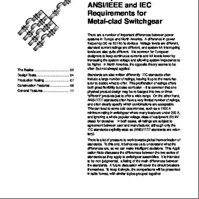
Comparison Between Ansi And Iec_metalcladswitcgear 2w4e2j
February 2022 0
Comparison Between Aac And Clc 23i4o
December 2021 0
Comparison Between Daoism And Christianity 4j5e1h
December 2019 40
October 2019 46
More Documents from "Ashok Pradhan" 691z26
Comparison Between Edge And Screw Dislocation.docx l3g6m
October 2019 59
What Is Draft Allowance m3e2i
December 2019 64
01 Thermodynamic Process Theory21 3v4c6l
December 2019 39
Is Electric Current A Scalar Or Vector Quantity 115i3j
July 2022 0
Lean Tpm - Downtime Waste Controls 60h5d
October 2021 0