Dahlander Winding 35502
This document was ed by and they confirmed that they have the permission to share it. If you are author or own the copyright of this book, please report to us by using this report form. Report 3b7i
Overview 3e4r5l
& View Dahlander Winding as PDF for free.
More details w3441
- Words: 383
- Pages: 1
3 Dahlander winding To run the machine at lower rotational speed, power supply is connected to terminals 1U, 1V and 1W. The other terminals (2U, 2V, 2W) remain unconnected (Fig. 5). To use higher speed, power supply is assigned to terminals 2U, 2V and 2W.
Electric motor operating principles and circuits Dahlander winding (low speed)
Dahlander winding (high speed)
L1 1U
2U
2W 1W 1V 2V
2U
Important: Terminals 1U, 1V and 1W must be interconnected in this case. Failure to provide this jumper („star connection“) will result in destruction of the windings (Fig. 6).
L1
1U
L3
2V
2W
1V
1W
L2
Windings
L2
L3
6
Windings L1
L2
L3
Note: In or-controlled systems, the „star“ or must always be switched on before the mains or for the high speed! 1U
1V
1W
2U
2V
2W
1U
1V
1W
2U
2V
2W
L1
L2
L3
Two separate windings Here, again, power supply is connected to terminals 1U, 1V and 1W for the lower speed, with terminals 2U, 2V and 2W remaining unconnected (Fig. 7). For higher speed, the power supply must be wired to terminals 2U, 2V and 2W. Note: A star connection („jumper“) must not be used in this case.
Terminal board
Terminal board
Fig. 5
Fig. 6
Failure to observe this rule would result in destruction of the windings. From the comparison of the connecting diagrams for motors with Dahlander winding and units with separate winding, it becomes clear that the difference between the circuits must be carefully noted when selecting switching devices. Note: A switching device for a Dahlander motor must never be used on a motor with two windings and vice versa! Once again, two phases are interchanged to reverse the motor direction. If a pole-changing switch („pole changer“) is used, it is recommended to effect phase interchange upstream of the switching device since changing phases on the motor would involve re-wiring 2 x 2 terminals, i.e. the risk of confusing conductors is much higher in this case.
Two separate windings (high speed) L1
Two separate windings (low speed) L1
2U
1U
1W
L3
L2
Windings L1
1U
2U
Terminal board
Fig. 7
2W
1V
2V
L3
L2
Windings L2
1V
2V
L3
1W
1U
1V
1W
2U
2V
2W
L1
L2
L3
2W
Terminal board
Fig. 8
Related Documents 3m3m1z

Dahlander Winding 35502
October 2019 410
Dahlander-schaltung o142l
November 2019 49
Motor Dahlander 83x4q
April 2020 28
Laporan Motor Dahlander u4v7
May 2021 0
Motor Dahlander 83x4q
November 2019 164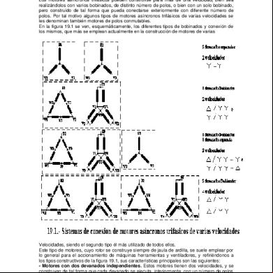
Conexion Dahlander i6j6
November 2019 159More Documents from "Sreekanth Raveendran" 542p4m

22689403 Iec 60038 Voltage Classifications 4x5f5a
October 2019 185
Cu Lugs Ferrules 61m27
January 2022 0
Socket And Switch Height 4s1d4f
December 2019 37
Dahlander Winding 35502
October 2019 410
6l6m1j
December 2019 67