Dk Butterfly Valve - Catalogue 5v2r67
This document was ed by and they confirmed that they have the permission to share it. If you are author or own the copyright of this book, please report to us by using this report form. Report 3b7i
Overview 3e4r5l
& View Dk Butterfly Valve - Catalogue as PDF for free.
More details w3441
- Words: 24,406
- Pages: 28
DK카다로그최종 2009.4.4 3:22 PM 페이지1
CO., LTD. HEAD OFFICE #75-8, MORA-DONG, SASANG-GU, BUSAN, KOREA TEL +82-51-305-3770 FAX +82-51-305-3737 INTERNET ADDRESS http://www.dkvalve.com E-MAIL ADDRESS [email protected]
KSA Cert No. 0062
KAB-QC-30
ISO 9001 Cert No. QMS-0549
BUTTERFLY VALVES
DK카다로그최종 2009.4.4 3:22 PM 페이지3
Advantages of butterfly valve
Index
Butterfly valve is much smaller than other valve designs. The results are saving in materials, less weight, small space requirement, and easy installation and operation. The liner materials used in the construction of DK butterfly valve are either Elastomer or TEFLONⓇ. Wafer construction provides maximum strength under conditions of pipeline strain. DK performs three basic functions of stopping flows, controlling flow and regulating flows and pressure with several advantage functions such as;
Contents
•Tight shut off •Less fluid resistance achieved through smooth flow •Low pressure drop •On-off or throttling applications •Suitable for automation with low operating torque and 90 degree operating angle •Reduced weight and installation space •No flange gasket •Quick fitting and dismantling •Easy replacement and renewable seat
Concentric rubber lined butterfly valve
04
2 piece split body PTFE lined butterfly valve
12
Double eccentric High Performance butterfly valve
14
Triple eccentric High Performance butterfly valve
17
Dual plate check valve
20
Engineering data
22
BL301
BG301
Wafer, Lever Op Size : 40~300mm (1½″~12″)
Wafer, Gear Op Size : 200~1000mm (8″~ 40″)
BL302
BG302
Full Lug, Lever Op Size : 40~300mm (1½″~12″)
Full Lug, Gear Op Size : 40~1000mm (1½″~40″)
BL303
BG303
Flange, Lever Op Size : 40~300mm (1½″~12″)
Flange, Gear Op Size : 40~1000mm (1½″~40″)
BL301T
BG301T
Wafer Teflon Lined Lever Op Size : 40~150mm (1½″~6″)
Wafer Teflon Lined Gear Op Size : 200~800mm (8″~ 32″)
BL301E
BG301E
High Performance Wafer, Lever Op Size : 50~150mm (2″~6″)
High Performance Eccentric, Gear Op Size : 50~1000mm (2″~ 40″)
BE301
BP301
Wafer, Pneumatic Op Size : 40~1000mm (1½″~40″)
Wafer, Electric Op Size : 40~1000mm (1½″~40″)
BC301
BW301
Valve configurations scale drawing to actual size
BALL
GATE
BUTTERFLY
GLOBE
PLUG
Application
POWER PLANT
FACTORY
PETROLEUM
STEEL WORKS
SHIPS
WATER TREATMENT
CHEMISTRY
FOODS
MINING
HOUSING
GAS
LEISURE FACILITY
AIR CONTROL
PAPER MAKING
This catalog remains the property of m/s DK Co., Ltd. Alternation of dimensions, materials, weight and others are reserved and subject to modification without pre-notice
02
DK Co., Ltd.
Wafer Center wheel Op Size : 40~300mm (1½″~12″)
Chain wheel Op Gear Op Size : 40~1000mm (1½″~40″)
DK Co., Ltd.
03
DK카다로그최종 2009.4.4 3:22 PM 페이지5
DK
Leak-tightness at Line stream, shaft ages and the atmosphere A perfect zero leakage seal at bi-direction is obtained by the compression of the inner between the valve body and the edge of the disc. A perfect zero leakage seal is provided by means of flatted liner area around both up and down shaft ages and the spherically machined disc. Since the seat stem hole is smaller than the stem diameter, there is a compression fit forming a secondary seal. The seal insures that no fiuid will leak to atmosphere.
DK
Specifications Standard According to ISO 5752 - BS 5155 - MSS SP 67 - API 609
Product range 40mm up to 1000mm(1½″~40″)
Pressure range Designed for maximum working pressure of 16bar (240psi)
Flange connections
Mounting plate in accordance with ISO standard
Heavy duty top bushing adsorbs side thrust load (PTFE optional)
Piping alignment Flange bolt alignment and installation suit for multi-national standard such as JIS, DIN, ANSI and BS flange standard
Sealing Hub seal is provided by preloaded between flatted seat surface and spherically machined and polished disc positions
The shape of valve body has been so designed as to allow flange bolt alignment onto following standards. Wafer type valve has been successfully developed to fit multi functional application onto either connection standard in the same configuration, mainly ISO PN 6, 10, 16, 20 ANSI B 16.1 CL. BS 4504 PN6, PN10, PN16 AS 2109 Table D and E MSS SP 44 CL. 150 ANSI B 16.5 CL. 150 BS 10 Table D and E JIS B 2210 5K, 10K, 16K and 20K
Materials Body
·Cast iron ·Ductile iron ·Carbon steel ·Stainless steel ·Bronze
ASTM A 126 Cl. B ASTM A 536 Gr 65-45-12 ASTM A 216 WCB ASTM A 351 Gr CF8-CF8M ASTM B 62
Disc
·Ductile iron ·Stainless steel ·Aluminum bronze ·Coated
ASTM A 536 Gr 65-45-12 ASTM A 351 Gr CF8-CF8M ASTM B 148 Cl. C95500 EPDM, Viton, Buna-N, etc
Stem
·Stainless steel ·Stainless steel ·Stainless steel ·Stainless steel ·K-Monel
ASTM A 276 304 ASTM A 276 410 ASTM A 276 316 17-4PH ASTM A 564 TYPE 630 ASTM B 164
Seat
Elastomer ·EPDM ·NBR ·Viton ·Silicon ·Neoprene
Working temperature -10℃ ~ +180℃ -10℃ ~ +170℃ -20℃ ~ +150℃ -20℃ ~ +120℃ -10℃ ~ +170℃
Packing
·EPDM ·NBR ·Viton
Gland
·PP
Operating Hand lever with notch plate Manual worm gear With locking device Electric/Pneumatic actuator Hydraulic actuator Chainwheel gear box
Testing Liner Retained resilient seat to valve enables easy replacement and isolates the body and stem from the flow. Special design of built-in O-ring provides positive flange sealling with no pipeline gasket required.
Disc edge Spherically machined and polished
API598 MSS SP 61, ANSI B 16.104
disc edge provides full concentric sealing, lower lever torque, longer seat life and positive shut-off closed at both directions.
Body Face to face dimension is in accordance with API and ISO standard.
04
DK Co., Ltd.
DK Co., Ltd.
05
DK카다로그최종 2009.4.4 3:22 PM 페이지7
DK
DK
WAFER BODY ØU
ØU
m-ØS
K
45°
45°
m-ØP
Y ØP ØN
ØP ØN
G Top flange I
G
Top flange
I
Flange Centring:ØC Holes dia:ØE No.of tap holes:F
Flange O h2 h1
h1
H
H
h2
O
Centring:ØC Holes dia:ØE No.of tap holes:F
L
Ød ØD
Ød ØD
200A~300A
Valve dimensions 1 ½″ 2″ 2 ½″ 3″ 4″ 5″ 6″ 8″ 10″ 12″
40 50 65 80 100 125 150 200 250 300
Unit(mm)
ØD
Ød
L
H
h1
h2
86 105 114 129 155 180 207 260 331 377
40 52 65 80 100 125 150 198 248 298
41 43 46 46 52 56 56 60 68 78
205 227 241 263 290 319 347 433 546 601
58 66.5 71 83 95 110 124 163 227 252
124 130.5 140 150 163 178 191 238 285 315
Stem ØU G 10 14 14 14 16 19 19 22 28 28
8 10 10 10 12 15 15 18 20 20
Top flange to ISO 5211 ØP Type ØN m F07 F07 F07 F07 F07 F07 F07 F07 F10 F10
90 90 90 90 90 90 90 90 125 125
70 70 70 70 70 70 70 70 102 102
4 4 4 4 4 4 4 4 4 4
Øs
9 9 9 9 9 9 9 9 12 12
O
WT (kg)
ØD
Ød
L
H
h1
h2
10 11 11 11 11 12 12 13 15 15
3.1 3.7 4 4.4 5.9 8.9 9 11 20 31.5
14″ 350 416 16″ 400 475 18″ 450 535 20″ 500 590 24″ 600 695 28″ 700 800 30″ 750 857 32″ 800 920 36″ 900 1020 40″ 1000 1125
327 387 438 477 560 690 729 785 900 990
78 102 114 127 154 165 180 180 180 200
675 817 877 1008 1180 1355 1445 1495 1625 1802
271 343 366 421 493 580 656 630 690 790
324 369 406 485 570 574 615 669 671 842
ØU
G
Stem I
32 35 38 45 50 70 70 80 80 90
19.5 -
45 60 60 60 60 120 120 140 140 140
Y
K
5 5 5 5 5 5 5.5 5.5 5.5
10 10 10 10 10 10 14 14 14
2 ″ 2.5 ″ 3 ″ 4 ″ 5 ″ 6 ″ 8 ″ 10 ″ 12 ″ 50 65 80 100 125 150 200 250 300
LEVER
HA P
228 210
246 210
268 210
292 262
327 358.5 445 262 262 297
GEAR
HA P W
254 150 150
264 150 150
280 150 150
316 150 150
351 382.5 469 150 150 225 150 150 190
HA
ØW
Dimensions
Unit(mm)
Inch mm
568 270 250
636 270 250
Top flange to ISO 5211 Øs Type ØN ØP m F10 F14 F14 F16 F16 F25 F25 F25 F30 F30
125 175 175 230 230 230 300 300 300 300
102 140 140 190 190 190 250 250 250 250
4 4 4 6 6 6 6 6 6 6
12 18 18 19 19 18.5 22 22 22 22
O
WT (kg)
20 23 23 34 34 35 35 35 38 40
43 63.5 99 114.5 214.5 377 460 542 699 977
refer to flange drilling on page 24
P
Size
HA
HA
DK Co., Ltd.
Unit(mm)
Size Inch mm
Dimensions
06
Valve dimensions
refer to flange drilling on page 24
P P
Size 16″ ~ 40″
ØW
Size Inch mm
L
Inch mm HA P GEAR W Size
Unit(mm)
14 ″ 16 ″ 18 ″ 20 ″ 22 ″ 24 ″ 28 ″ 30 ″ 32 ″ 36 ″ 40 ″ 350 400 450 500 550 600 700 750 800 900 1000 657 270 300
807 330 400
867 1013 1059 1172 1310 1355 1455 1510 1775 330 330 330 330 320 320 320 330 330 400 400 400 400 700 700 700 800 800
DK Co., Ltd.
07
DK카다로그최종 2009.4.4 3:22 PM 페이지9
DK
DK
FULL LUG BODY ØU
m-ØS
45°
m-ØS
K
45°
ØU
G G
Top flange I
Top flange
O h1
h1
H
H
h2
Centring:ØC Bolt Dia:E(M) No.of tap holes:F
h2
Flange Centring:ØC Bolt Dia:E(M) No.of tap holes:F
O
Size 10″ ~ 12″
Flange
Ød
1 ½″ 2″ 2 ½″ 3″ 4″ 5″ 6″ 8″ 10″ 12″
40 50 65 80 100 125 150 200 250 300
Unit(mm)
ØD
Ød
L
H
h1
h2
86 100 112 126 153 182 210 255 328 374
40 52 65 80 100 125 150 198 248 298
41 43 46 46 52 56 56 60 68 78
205 235 237 255 292 317 357 412 519 588
58 72.5 75.5 82 99.5 111 134 163 218 249
124 130.5 129.5 143 160.5 177 191 217 267 295
Stem ØU G 10 14 14 14 16 19 19 22 28 28
8 10 10 10 12 15 15 18 20 20
Top flange to ISO 5211 ØP Type ØN m F07 F07 F07 F07 F07 F07 F07 F07 F10 F10
90 90 90 90 90 90 90 90 125 125
70 70 70 70 70 70 70 70 102 102
4 4 4 4 4 4 4 4 4 4
Øs
9 9 9 9 9 9 9 9 12 12
Valve dimensions
O
WT (kg)
Size Inch mm
10 11 11 11 11 12 12 13 15 15
3.5 4.1 5.5 6.8 8.6 10.5 12.5 21.4 29.3 44
14″ 16″ 18″ 20″ 24″ 28″ 30″ 32″ 36″ 40″
Unit(mm)
ØD
Ød
L
H
h1
h2
350 416 400 475 450 535 500 586 600 695 700 800 750 857 800 920 900 1020 1000 1125
327 387 438 477 560 690 729 785 900 990
78 102 114 127 154 165 180 180 180 200
675 817 877 1008 1180 1355 1445 1495 1625 1802
271 343 366 421 493 580 656 630 690 790
324 369 406 485 570 574 615 669 671 842
ØU
G
32 35 38 45 50 70 70 80 80 90
19.5 -
Stem I
Y
K
45 60 60 60 60 120 120 140 140 140
5 5 5 5 5 5 5.5 5.5 5.5
10 10 10 10 10 10 14 14 14
refer to flange drilling on page 24
233 227
245 227
262 227
292 285
318 285
359 285
431 285
GEAR
HA P W
257 130 150
265 130 150
280 130 150
314 130 150
359 160 190
397 160 190
452 210 250
HA
HA P
ØW
LEVER
ØW
2 ″ 2.5 ″ 3 ″ 4 ″ 5 ″ 6 ″ 8 ″ 10 ″ 12 ″ 50 65 80 100 125 150 200 250 300
Inch mm
HA
HA
DK Co., Ltd.
Dimensions
Unit(mm)
Size
553 210 250
614 270 300
Top flange to ISO 5211 Øs Type ØN ØP m F10 F14 F14 F16 F16 F25 F25 F25 F30 F30
125 175 175 230 230 230 300 300 300 300
102 140 140 190 190 190 250 250 250 250
4 4 4 6 6 6 6 6 6 6
12 18 18 19 19 18.5 22 22 22 22
O
WT (kg)
20 23 23 34 34 35 35 35 38 40
62.2 112 153 199 283 490 598 677 874 1221
refer to flange drilling on page 24
P
Dimensions
P
P
Size 16″~ 40″
ØD
Valve dimensions Size Inch mm
L
Ød
L
ØD
08
Y
I
ØP ØN
ØP ØN
Inch mm HA GEAR P W Size
Unit(mm)
14 ″ 16 ″ 18 ″ 20 ″ 22 ″ 24 ″ 28 ″ 30 ″ 32 ″ 36 ″ 40 ″ 350 400 450 500 550 600 700 750 800 900 1000 657 270 300
807 330 400
867 1013 1059 1172 1310 1355 1455 1510 1775 330 330 330 330 320 320 320 330 330 400 400 400 400 700 700 700 800 800
DK Co., Ltd.
09
DK카다로그최종 2009.4.4 3:22 PM 페이지11
DK
DK
DOUBLE FLANGE BODY ØU
m-ØS
m-ØS
K
45°
45°
ØU
Y G
G
ØP ØN
Top flange I
Top flange
Flange Centring:ØC Bolt Dia:E(M) No.of tap holes:F
Flange O h2 h1
h1
H
H
h2
O
Centring:ØC Bolt Dia:E(M) No.of tap holes:F
Ød
Ød
L
Valve dimensions Size Inch
mm
1 ½″ 2″ 2 ½″
40 50 65 80 100 125 150 200 250 300
3″ 4″ 5″ 6″ 8″ 10″ 12″
I
ØP ØN
Unit(mm)
Ød
L
H
h1
h2
40 52 65 80 100 125 150 198 248 298
41 43 46 46 52 56 56 60 68 78
205 240 247 266 298 331 363 412 506 538
58 77.5 87.5 92.5 105 125 140 163 205 248.5
124 130.5 129.5 143 160.5 177 191 217 267 295
Stem ØU G 10 14 14 14 16 19 19 22 28 28
8 10 10 10 12 15 15 18 20 20
Top flange to ISO 5211 ØP Type ØN m F07 F07 F07 F07 F07 F07 F07 F07 F10 F10
90 90 90 90 90 90 90 90 125 125
70 70 70 70 70 70 70 70 102 102
4 4 4 4 4 4 4 4 4 4
Øs
9 9 9 9 9 9 9 9 12 12
Valve dimensions Size
O
WT (kg)
Inch
mm
10 11 11 11 11 12 12 13 15 15
6.2 6.8 8.9 10.2 14.5 16.8 19.8 31.2 46.2 58.8
14″ 16″ 18″ 20″ 24″ 28″ 30″ 32″ 36″ 40″
350 400 450 500 600 700 750 800 900 1000
Unit(mm)
Ød
L
H
h1
h2
327 387 438 477 560 690 729 785 900 990
78 102 114 127 154 165 180 180 180 200
675 817 877 1008 1180 1355 1445 1495 1625 1802
271 343 366 421 493 580 656 630 690 790
324 369 406 485 570 574 615 669 671 842
ØU
G
Stem I
32 35 38 45 50 70 70 80 80 90
19.5 -
45 60 60 60 60 120 120 140 140 140
Y
K
5 5 5 5 5 5 5.5 5.5 5.5
10 10 10 10 10 10 14 14 14
refer to flange drilling on page 24
Dimensions HA P
238.5 257.5 272.5 298 227 227 227 285
333 285
365 285
433 285
GEAR
HA P W
262.5 277.5 290.5 320 130 130 130 130 150 150 150 150
374 160 190
403 160 190
454 210 250
558 602.5 220 270 250 300
ØW
ØW
DK Co., Ltd.
LEVER HA
HA
10
2 ″ 2.5 ″ 3 ″ 4 ″ 5 ″ 6 ″ 8 ″ 10 ″ 12 ″ 50 65 80 100 125 150 200 250 300
Inch mm
Dimensions
P
Unit(mm)
Size
Top flange to ISO 5211 Øs Type ØN ØP m F10 F14 F14 F16 F16 F25 F25 F25 F30 F30
125 175 175 230 230 230 300 300 300 300
102 140 140 190 190 190 250 250 250 250
4 4 4 6 6 6 6 6 6 6
12 18 18 19 19 18.5 22 22 22 22
O
WT (kg)
20 23 23 34 34 35 35 35 38 40
66.6 96 147 161 292 539 658 745 944 1307
refer to flange drilling on page 24
HA
P
P
Size 16″ ~ 40″
L
Inch 14 ″ mm 350 HA 657 270 GEAR P 300 W Size
Unit(mm)
16 ″ 18 ″ 20 ″ 22 ″ 24 ″ 28 ″ 30 ″ 32 ″ 36 ″ 40 ″ 400 450 500 550 600 700 750 800 900 1000 807 330 400
867 1013 1059 1172 1310 1355 1455 1510 1775 330 330 330 330 320 320 320 330 330 400 400 400 400 400 400 400 800 800
DK Co., Ltd.
11
DK카다로그최종 2009.4.4 3:22 PM 페이지13
DK Ⓡ
TWO PIECE SPLIT BODY TEFLON LINED
DK
TWO PIECE BODY TEFLON LINED
TeflonⓇ covered one-piece stainless steel disc and shaft
m-ØS
The seat configuration of the resiliency of elastomer back-up ring Ⓡ and the chemical resistance of a Teflon makes valve with more suitable for application such as toxic and corrosive media where elastomers are unsuitable. One-piece disc/shaft provide the minimum obstruction to fluid flow since shaft-attachment obstruction is eliminated. This results in excellent flow characteristics and makes a valve suited for the processing industries because fluid is limited to the seat and disc only
K
45°
ØU
Y
I
ØP ØN
Size 8″
G Top flange
I
Flange
h2
O
Centring:ØC Holes dia:ØE No.of tap holes:F
H
One-piece Stainless steel disc/shaft
h1
Extended covering Stainless steel shaft
Application
Ød
Chemicals, acids, corrosive products
General Characteristics Two piece-body Bi-directional Centred butterfly 1 piece stem and burrerfly
Valve dimensions Coated surface
Construction Body cast steel / stainless steel Stainless steel butterfly PTFF lined PTFF sleeve with rubber backup pad
Coating Painting: oven backed epoxy powder coating, 150
Working Conditions 5.5 Bar pressure
Hydraulic Tests 1.1 times the maximum working pressure
Connection Between flanges ISO PN 10/16, ANSI B 16.5.150
Handling Possibilities Lever Gear box with opening indicator Single or double effect pneumatic actuator Electric motors 220/380 V mono/tri
12
DK Co., Ltd.
Size 16″ ~ 24″
L
ØD
Stainless steel disc
Cut away PFA coated Disc-Stem Stainless steel with finish allows proper secondary seal and bearing conditions at seat hole Extended covering from primary seal through secondary seal into seat hole area assures stem isolation Complete encapsulation affords complete isolation of steel disc PFA-covered disc suitable not only for chemically resistant but for handling abrasives in the processing industries
Material standard Body Disc Seat
Cast iron - Aluminium - Ductile iron Hard rubber lined steel - SS 304-316 All kinds of rubber
Unit(mm)
Size Inch mm
ØD
Ød
L
H
50 65 80 100 125 150 200 250 300 350 400 450 500
102 115 128 153 183 210 259 328 374 416 475 535 586
52 65 80 100 125 150 198 248 298 327 387 438 477
43 46 46 52 56 56 60 68 78 78 102 114 127
227 241 263 290 319 347 433 546 601 675 817 877 1008
2″ 2 ½″ 3″ 4″ 5″ 6″ 8″ 10″ 12″ 14″ 16″ 18″ 20″
h1
h2
66.5 130.5 71 140 83 150 95 163 110 178 124 191 163 238 227 285 252 315 271 324 343 369 366 406 421 485
ØU
G
Stem I
Y
K
14 14 14 16 19 19 22 28 28 32 35 38 45
10 10 10 12 15 15 18 20 20 19.5 -
38 38 38 38 38 38 38 45 45 45 60 60 60
5 5 5
10 10 10
Top flange to ISO 5211 Øs Type ØN ØP m F07 F07 F07 F07 F07 F07 F07 F10 F10 F10 F14 F14 F16
90 90 90 90 90 90 90 125 125 125 175 175 230
70 70 70 70 70 70 70 102 102 102 140 140 190
4 4 4 4 4 4 4 4 4 4 4 4 6
9 9 9 9 9 9 9 12 12 12 18 18 19
O
WT (kg)
11 11 11 11 12 12 13 15 15 20 23 23 34
4.3 4.5 4.9 6.3 8.9 9.4 11.5 21 32 43.6 64 99.7 115
DK Co., Ltd.
13
DK카다로그최종 2009.4.4 3:22 PM 페이지15
DK
DK
WAFER BODY ( SEMI LUG )
DOUBLE ECCENTRIC HIGH PERFORMANCE
A
Specifications Product range B
40mm up to 1000mm(1½″~40″)
P Ø
Pressure Temperature range Metal seat type WMP 4.90Mpa (50kgf/㎠) WMT 450 deg. Cels. Teflon seat type WMP 1.96Mpa (20kgf/㎠) WMT 230 deg. Cels.
ØU
KEY
n-ØS
MSS SP 44 CL. 150, 300 ANSI B 16.5 CL. 150, 300 BS 10 Table D and E JIS B 2210 10K, 16K and 20K
Hole(Tap)
H2
ISO PN 10, 16, 20 and 25 ANSI B 16.1 CL. BS 4504, PN 10, PN 16 AS2129 Table D and E
I
Flange connections
Test and Inspection
Ød
Conforms to API 598 Body test 1.5 times the maximum working pressure with water. The test is performed on the assembled valve with the disc in half open position Seat and shaft seal test 1.1 times the maximum working pressure. The shaft seal test and inspection is conducted simultaneously with seat test
FLOW Size 2″~ 6″
H1
Seat Construction
Size 8″~ 12″
L
Fire-safe seat RTFE Seat
Flat Metal Seat
Rubber Seat
Fire Safe PTFE with Metal
Materials Body
Ductile iron Carbon steel Stainless steel Aluminum bronze
ASTM A 536 Gr 65-45-12 ASTM A 216 WCB ASTM A 351 Gr CF8-CF8M ASTM B 148 C95500
Disc
Stainless steel Aluminum bronze
ASTM A 351 Gr CF8-8M ASTM B 148 C95500
Stem
Stainless steel Stainless steel Stainless steel Stainless steel K-Monel
ASTM A 276 304 ASTM A 276 410 ASTM A 276 316 17-4PH ASTM A 564 TYPE 630 ASTM B 164
Before burnt
Seat
Elastomer Ⓡ Teflon Metal
DK Co., Ltd.
After burnt
Features Double eccentric disc and stem Spherical sealing structure Low operating torque Low friction and wear Renewable catridge seat
Application Chemical processing Power plant Hydrocarbon processing Shipbuilding
14
Valve dimensions
After a fire when the R-PTFE seat has burned away, the supplementary metal sealing seat will be activated automatically and prevent from excessive flow
Unit(mm)
Size Inch mm
Ød
L
H1
H2
50 65 80 100 125 150 200 250 300 350 400 450 500 550 600 650 700 750 800 900 1000
55 70 84 104 130 155 205 225 305 340 380 430 480 540 590 640 690 736 786 890 980
60 48 48 54 57 57 63 71 81 92 102 114 127 170 154 210 220 197 190 216
62 72 82 92 110 130 180 238 275 310 325 365 405 410 470 487 510 574 580 678 724
182 192 202 212 232 247 297 350 370 445 480 510 525 555 580 664 686 735 735 890 950
2″ 2 ½″ 3″ 4″ 5″ 6″ 8″ 10″ 12″ 14″ 16″ 18″ 20″ 22″ 24″ 26″ 28″ 30″ 32″ 36″ 40″
Stem
Top flange to ISO 5211 ØP B n
I
ØU
Key
Type
A
Øs
40 40 40 40 40 40 55 60 65 80 80 80 95 95 95 95 95 95 95 95 95
14 14 14 14 18 18 22 28 32 35 40 45 50 60 60 65 70 75 80 90 100
5×5×29 5×5×29 5×5×29 5×5×29 5×5×29 5×5×29 6×6×44 8×7×44 8×7×44 10×8×44 10×8×69 14×9×69 18×11×99 18×11×99 18×11×99 18×11×99 20×12×99 20×12×99 20×14×99 25×14×119 28×16×129
F07 F07 F07 F07 F07 F07 F07 F10 F10 F10 F14
82 82 82 82 82 82 111 132 132 156 156
70 70 70 70 70 70 96 114 114 136 136
70 70 70 70 70 70 102 102 102 140 140
4 4 4 4 4 4 4 4 4 4 4
10 10 10 10 10 10 10 10 10 10 10
F14 F16 F16 F16 F16 F25 F25 F25 F30 F30
156 200 200 200 200 300 300 300
136 180 180 180 180 270 270 270
140 165 165 165 165 254 254 254 298 298
4 4 4 4 4 8 8 8 8 8
10 10 10 10 10 18 18 18 22 22 DK Co., Ltd.
15
DK카다로그최종 2009.4.4 3:22 PM 페이지17
DK
FULL LUG / FLANGE BODY
DK
TRIPLE OFFSET METAL SEAT Specifications
A
A
Triple offset Design Princlples
Product range
B
B
80mm ~ 1200mm P Ø
P Ø
Design standard
ØU
ANSI B16.34 BS5155, MSS SP68, API609
Flange connections
ØU KEY
API 609, BS 5155, DIN 3840
I
I
n-ØS
n-ØS
Pressure Temperature range ASME/ANSI 16.34
Hole(Tob)
Face to Face Dimension ANSI B16.10 ISO 5752, API 609 BS 5155
H2
H2
Hole(Tob)
Testing API 598, MSS-SP 61, ANSI 16.104 Ød
FLOW
H1
H1
Material
L
Valve dimensions Ød
L
H1
H2
50 65 80 100 125 150 200 250 300 350 400 450 500 550 600 650 700 750 800 900 1000
55 70 84 104 130 155 205 225 305 340 380 430 480 540 590 640 690 736 786 890 980
60 48 48 54 57 57 63 71 81 92 102 114 127 170 154 210 220 197 190 216
62 72 82 92 110 130 180 238 275 310 325 365 405 410 470 487 510 574 580 678 724
182 192 202 212 232 247 297 350 370 445 480 510 525 555 580 664 686 735 735 890 950
3″ 4″ 5″ 6″ 8″ 10″ 12″ 14″ 16″ 18″ 20″ 22″ 24″ 26″ 28″ 30″ 32″ 36″ 40″
16
DK Co., Ltd.
Carbon Steel, Ductile iron, Stainless Steel
Disc
Aluminium Bronze
Stem
Stainless steel
Seat
Stellite overlay, Laminated Metal Seat, Solid Metal Seat
Unit(mm)
Size Inch mm 2″ 2 ½″
Body
Stem
Top flange to ISO 5211 ØP B n
Features
I
ØU
Key
Type
A
Øs
40 40 40 40 40 40 55 60 65 80 80 80 95 95 95 95 95 95 95 95 95
14 14 14 14 18 18 22 28 32 35 40 45 50 60 60 65 70 75 80 90 100
5×5×29 5×5×29 5×5×29 5×5×29 5×5×29 5×5×29 6×6×44 8×7×44 8×7×44 10×8×44 10×8×69 14×9×69 18×11×99 18×11×99 18×11×99 18×11×99 20×12×99 20×12×99 20×14×99 25×14×119 28×16×129
F07 F07 F07 F07 F07 F07 F07 F10 F10 F10 F14
82 82 82 82 82 82 111 132 132 156 156
70 70 70 70 70 70 96 114 114 136 136
70 70 70 70 70 70 102 102 102 140 140
4 4 4 4 4 4 4 4 4 4 4
10 10 10 10 10 10 10 10 10 10 10
F14 F16 F16 F16 F16 F25 F25 F25 F30 F30
156 200 200 200 200 300 300 300
136 180 180 180 180 270 270 270
140 165 165 165 165 254 254 254 298 298
4 4 4 4 4 8 8 8 8 8
10 10 10 10 10 18 18 18 22 22
Zero leakage (bubble tightness) Shut off and throttling of gaseous and liquid media Low operating torque Long sevice life High temperature compatibility
Characteristics and Merits Excellent durability of seat part and low operating torque by non-rubbing characteristics with triple offset construction Bi-directional zero leakage service by resilient metal sealing and torque seating Unrestricted selection of face to face dimensions for API, ASME(ANSI), BS, ISO, etc. and perfect interchangeability of gate, ball, plug, high performance butterfly, and other valves Low emission by quarter turn construction and good performance at automation by virtue of low operating torque and low cost The valve stem is offset by seat(1st offset) and the valve seat surface center line is offset against the center line of pipe (2nd offset) and the conical axis is offset by valve center line (3rd offset: inclined cone) The 3rd offset completely eliminates rubbing. The seat surfaces of body and seal ring in triple offset valve with the inclined “cone-in cone” and this design provides excellent sealing and seat part durability by slight wedging effect.
Laminated Metal Seat 316ss+ Graphite Laminated
Hard Faced Seat
Solid Metal Seat
Body Seat The valve seat shall be integrated with the body Stellite or stainless steel shall be applied on the seating surfaces of valve body The valve seat is designed for inclined cone to ensure non-rubbing, nonjamming, bi-directional shutoff, and zero leakage
Seal Ring (Laminated) The seal ring shall be resilient stainless steel lamalla, alternated by graphite, aramid fiber and cermic fiber layers The surface ing between seal ring and body seat is an inclined cone type and the inclined angle generates a slight wedging effect With a seat retainer ring bolted to the disc, the seal ring is fixed to disc not so tightly that it can be replaced easily DK Co., Ltd.
17
DK카다로그최종 2009.4.4 3:22 PM 페이지19
DK
150LB / 300LB
DK
600LB / 900LB
ØW
H3 H2
L
H
H3 H2
L
H3 H2
L
L
P
H1
H1
H1
P
150LB Manual Gear Operating Type Size Inch
mm
6″ 8″ 10″ 12″ 14″ 16″ 18″ 20″ 24″ 28″ 30″ 32″ 36″ 40″ 42″ 48″
150 200 250 300 350 400 450 500 600 700 750 800 900 1000 1050 1200
Unit(mm)
H
H1
H2
H3
300 310 335 390 420 500 515 565 635 775 785 840 910 925 980 1140
245 260 285 335 365 435 452 500 570 685 695 750 820 835 860 1020
180 195 225 265 290 340 360 395 465 570 600 630 690 720 750 845
35 35 65 80 80 80 80 80 110 130 130 130 160 175 175 200
WAFER 57 64 71 81 92 102 114 127 154 165 165 190 200 216 251 276
L ( F TO F ) LUG FLANGE 57 64 71 81 92 102 114 127 154 165 165 190 200 216 251 276
140 152 165 178 190 216 222 229 267 292 318 318 330 410 410 470
P
ØW
206 206 206 230 230 279 279 312 312 371 371 425 425 425 513 513
300 300 300 400 400 450 450 560 560 630 630 710 710 710 800 800
WEIGHT (kg) WAFER LUG FLANGE 20 45 57 85 133 186 213 334 455 718 864 1090 1418 1743 2108 3004
22 47 61 91 142 199 229 364 492 777 934 1119 1553 1943 2343 3284
48 89 112 161 228 303 364 499 699 860 1085 1241 1716 2208 2488 3440
600LB Manual Gear Operating Type
Unit(mm)
Size Inch
mm
H
H1
H2
H3
6″ 8″ 10″ 12″ 14″ 16″ 18″ 20″ 24″
150 200 250 300 350 400 450 500 600
365 380 465 520 535 675 715 760 840
310 325 400 455 470 585 625 670 750
238 248 316 349 374 474 476 504 55
80 80 80 110 110 130 130 130 180
WAFER
L ( F TO F ) LUG FLANGE
78 102 117 140 155 178 200 216 232
78 102 117 140 155 178 200 216 232
210 230 250 270 290 310 330 350 390
P
ØW
230 230 279 312 312 371 371 425 425
400 400 450 560 560 630 630 710 710
WEIGHT (kg) WAFER LUG FLANGE 65 92 134 224 285 455 555 694 1093
72 102 187 259 329 520 635 804 1243
135 162 268 369 364 632 739 879 1423
Weight and dimensions are approximate
Weight and dimensions are approximate
300LB Manual Gear Operating Type Size Inch
mm
6″ 8″ 10″ 12″ 14″ 16″ 18″ 20″ 24″ 28″ 30″ 32″ 36″ 40″ 42″ 48″
150 200 250 300 350 400 450 500 600 700 750 800 900 1000 1050 1200
Unit(mm)
H
H1
H2
H3
330 350 395 450 490 545 605 645 740 910 940 970 1050 1110 1160 1270
280 295 340 395 425 480 540 580 650 820 850 880 960 990 1050 1150
199 218 251 296 331 377 410 440 515 640 690 720 780 800 840 950
65 80 80 80 80 110 110 130 130 200 200 200 200 200 200 250
L ( F TO F ) WAFER LUG FLANGE 59 73 83 92 117 133 149 159 181 229 241 241 260 300 300 320
59 73 83 92 117 133 149 159 181 229 241 241 260 300 300 320
140 152 165 178 190 216 222 229 267 292 318 318 330 410 410 470
P
ØW
206 230 230 230 279 279 312 312 371 371 425 425 425 513 513 536
300 400 400 400 450 450 560 560 630 630 710 710 710 800 800 900
WEIGHT (kg) WAFER LUG FLANGE 36 51 100 134 196 232 360 457 670 1193 1463 1661 2281 2214 2439 3384
39 56 112 150 229 277 433 549 805 1363 1658 1856 2511 2425 2649 3684
76 93 164 222 298 357 499 621 916 1417 1715 1957 2590 2585 2849 4106
900LB Manual Gear Operating Type Size Inch
mm
6″ 8″ 10″ 12″ 14″ 16″ 18″ 20″ 24″
150 200 250 300 350 400 450 500 600
Unit(mm)
H
H1
H2
H3
400 445 500 590 635 730 780 830 950
335 380 435 500 545 640 690 710 820
238 281 358 383 419 455 503 550 656
80 80 110 110 130 130 180 180 200
L ( F TO F ) WAFER LUG FLANGE 104 112 135 170 173 210 228 250 275
104 112 135 170 173 210 228 250 275
250 310 350 380 400 430 460 490 530
P
ØW
279 312 312 371 371 425 425 513 513
450 560 560 630 630 710 710 800 800
WEIGHT (kg) WAFER LUG FLANGE 89 134 224 298 376 570 691 905 1317
100 151 256 352 440 663 824 1069 1704
184 256 425 496 656 834 1044 1273 2506
Weight and dimensions are approximate
* Not specified class and size, please sales department
Weight and dimensions are approximate
18
DK Co., Ltd.
DK Co., Ltd.
19
DK카다로그최종 2009.4.4 3:22 PM 페이지21
DK Unit(mm)
300 (12 ″ )
125 250 150 300 400 600 900 1500
FF FF RF·R-56 RF·R-57 RF·R-57 RF·R-57 RF·R-57 RF·R-58
410 422 410 422 419 457 498 521
181 181 181 181 229 229 292 305
324 324 324 324 324 324 324 324
431.8 450.8 431.8 450.8 450.8 488.9 533.4 571.5
12 16 12 16 16 20 20 16
7/8 1⅛ 7/8 1⅛ 1¼ 1¼ 1⅜ 2
280 370 310 360 445 465 560 700
315 375 440 460 555 700
56 90 84 88 133 144 169 178
350 (14 ″ )
125 250 150 300 400 600 900 1500
FF FF · RF R-59 RF·R-61 RF·R-61 RF·R-61 RF·R-62 RF·R-63
451 486 451 486 483 492 521 578
184 222 184 222 273 273 356 356
356 356 356 356 356 356 356 356
476.2 514.3 476.2 514.3 514.3 527 558.8 635
12 20 12 20 20 20 20 16
1 1⅛ 1 1⅛ 1¼ 1⅜ 1½ 2¼
315 425 315 425 495 520 645 785
350 415 485 510 650 800
71 176 97 176 198 198 198 198
400 (16 ″ )
125 250 150 300 400 600 900 1500
FF FF RF·R-64 RF·R-65 RF·R-65 RF·R-65 RF·R-66 RF·R-67
514 540 514 540 537 565 575 641
191 232 191 232 305 305 384 384
406 406 406 406 406 406 406 406
539.7 517.5 539.7 571.5 571.5 603.2 615.9 704.8
16 20 16 20 20 20 20 16
1 1¼ 1 1¼ 1⅜ 1½ 1⅝ 2½
350 435 350 435 550 585 690 855
340 425 540 575 695 870
99 227 159 227 268 288 550 750
450 (18″ )
125 250 150 300 400 600 900 1500
FF FF RF·R-68 RF·R-69 RF·R-69 RF·R-69 RF·R-70 RF·R-71
549 597 549 579 594 613 638 705
203 264 203 264 362 362 451 468
457 457 457 457 457 457 457 457
577.8 628.6 577.8 628.6 628.6 654 685.8 774.7
16 24 16 24 24 20 20 16
1 1 1 1 1 1 1 2
⅛ ¼ ⅛ ¼ ⅜ ⅝ ⅞ ¾
370 495 370 495 635 635 800 985
390 485 625 625 800 1005
118 301 185 301 401 401 770 980
FF FF RF·R-72 RF·R-73 RF·R-73 RF·R-73 RF·R-74
606 654 606 654 648 683 699
213 292 219 292 368 368 451
508 508 508 508 508 508 508
635 685.8 635 685.8 685.8 723.9 749.3
20 24 20 24 24 24 20
1 1 1 1 1 1
⅛ ¼ ⅛ ¼ ½ ⅝ 2
375 520 380 520 670 670 740
395 510 660 660 745
180 373 243 373 421 640 1055
ØC
ØA
Weight (kg)
Flange Face
Unit(mm) ØA
Dimensions B
ØC
FF FF RF·R-22 RF·R-23 RF·R-23 RF·R-24 RF·R-24
105 111 105 111 111 143 143
54 54 60 60 60 70 70
60 60 60 60 60 60 60
120.6 127.0 120.6 127.0 127.0 165.1 165.1
4 8 4 8 8 8 8
5/8 5/8 5/8 5/8 5/8 7/8 7/8
145 170 155 155 175 225 225
155 175 180 225 225
3 4 3 3 3 6 7
500 ( 20 ″ )
125 250 150 300 400 600 900
125 250 150 300 400-600 900 1500
FF FF RF·R-25 · RF R-26 RF·R-26 RF·R-27 RF·R-27
124 130 124 130 130 165 165
60 60 67 67 67 83 83
73 73 73 73 73 73 73
139.7 149.3 139.7 149.3 149.3 190.5 190.5
4 8 4 8 8 8 8
5/8 3/4 5/8 3/4 3/4 1 1
150 180 165 175 195 250 250
165 195 195 250 250
4 5 4 4 4 7 8
600 ( 24 ″ )
125 250 150 300 400 600 900
FF FF RF·R-72 · RF R-73 RF·R-73 RF·R-73 RF·R-78
718 775 718 775 768 791 838
222 318 222 318 394 438 495
610 610 610 610 610 610 610
749.3 812.8 749.3 812.8 812.8 838.12 901.7
20 24 20 24 24 24 20
1 1 1 1 1 1 2
¼ ½ ¼ ½ ¾ ⅞ ½
435 585 435 582 685 785 950
425 575 675 775 965
258 541 394 598 743 981 1700
700 ( 28 ″ )
125 150
FF RF
832 832
321 321
711 711
840 840
24 24
1¼ 1¼
505 505
-
634 692
80 ( 3″ )
125 250 150 300 400-600 900 1500
FF FF RF·R-29 RF·R-31 RF·R-31 RF·R-31 RF·R-35
137 149 137 149 149 168 175
67 67 73 73 73 83 83
89 89 89 89 89 89 89
152.4 168.4 152.4 168.4 168.4 190.5 203.2
4 8 4 8 8 8 8
5/8 3/4 5/8 3/4 3/4 7/8 1⅛
160 195 175 190 210 240 270
180 205 210 235 270
5 7 6 7 7 13 14
750 ( 30 ″ )
125 150 300
FF RF RF RJ95
883 883 953
305 330 398
762 762 762
914.4 914.4 966.5
28 28 28
1¼ 1¼ 1¾
495 580 675
750
450 580 928
800 ( 32 ″ )
125 150
FF RF
920 940
356 356
813 813
950 950
28 28
1½ 1½
550 550
-
533 635
FF FF · RF R-36 RF·R-37 RF·R-37 RF·R-37 RF·R-37 RF·R-39
175 181 175 181 178 194 206 210
67 67 73 73 79 79 102 102
114 114 114 114 114 114 114 114
190.5 200.1 190.5 200.1 200.1 215.9 234.9 241.3
8 8 8 8 8 8 8 8
5/8 3/4 5/8 3/4 7/8 7/8 1⅛ 1¼
170 205 175 195 220 245 285 310
180 210 220 245 280 305
6 8 8 8 11 12 18 21
900 ( 36 ″ )
125 150 300
FF RF RF 98
1048 1048 1117
368 387 489
914 914 914
1085.8 1085.8 1168.4
32 32 32
1½ 1½ 2
580 605 835
-
656 685 1609
100 ( 4″ )
125 250 150 300 400 600 900 1500
1000 ( 40 ″ )
125 150
FF RF
1162 1162
419 419
1016 1016
1160 1160
28 28
1½ 1½
645 645
-
1065 1190
1050 ( 42 ″ )
125 150 300
FF RF RF
1219 1219 1289
432 432 568
1067 1067 1067
1257.3 1257.3 1339.8
36 36 36
1½ 1½ 2
650 650 890
-
1260 1386 2630
125 250 150 300 400 600
FF FF · RF R-41 RF·R-41 RF·R-41 RF·R-41
197 216 197 216 213 241
83 83 86 86 105 105
141 141 141 141 141 141
215.9 234.9 215.9 234.9 234.9 266.7
8 8 8 8 8 8
3/4 3/4 3/4 3/4 7/8 1
185 220 195 215 260 280
195 230 260 280
9 14 10 14 19 23
1200 ( 48 ″ )
125 150 300
FF RF RF
1384 1384 1366
524 524 629
1219 1219 1219
1422.4 1422.4 1543
44 44 44
1½ 1½ 2
750 750 -
-
2055 2180 2755
1350 (54 ″ )
150
RF
1549
540
1372
1593.8
44
1¾
815
-
2800
1500 (60 ″ )
150
RF
1715
660
1524
1759
52
1¾
-
-
3538
-
-
6350
-
-
-
Size
Series
Flange Face
50 ( 2″ )
125 250 150 300 400-600 900 1500
65 ( 2 ½″ )
125 ( 5″ )
Flange Bolt Number of Bolts Circle Bolts Diameter
Weight (kg)
125 250 150 300 400 600 900 1500
FF FF RF·R-43 RF·R-43 RF·R-45 RF·R-45 RF·R-45 RF·R-46
222 257 222 251 248 267 289 283
95 95 98 98 136 136 159 159
168 168 168 168 168 168 168 168
241.3 269.9 241.3 269.9 269.9 292.1 317.5 317.5
8 12 8 12 12 12 12 12
3/4 3/4 3/4 3/4 7/8 1 1⅛ 1⅜
190 240 210 235 300 315 370 430
210 250 300 320 360 425
10 19 16 19 31 33 53 59
200 ( 8″ )
125 250 150 300 400 600 900 1500
FF FF RF·R-48 RF·R-49 RF·R-49 RF·R-49 RF·R-49 RF·R-50
279 308 279 308 305 321 359 352
127 127 127 127 165 165 206 206
219 219 219 219 219 219 219 219
298.4 330.2 298.4 330.2 330.2 349.2 393.7 393.7
8 12 8 12 12 12 12 12
3/4 7/8 3/4 7/8 1 1⅛ 1⅜ 1⅝
215 280 245 280 350 375 435 505
250 290 345 370 440 510
19 36 32 36 36 68 89 97
250 (10″ )
125 250 150 300 400 600 900 1500
FF FF RF·R-52 RF·R-53 RF·R-53 RF·R-53 RF·R-53 RF·R-54
340 362 340 362 359 400 435 435
140 140 146 146 213 213 241 248
274 274 274 274 274 274 274 274
361.9 387.5 361.9 387.5 387.5 431.8 469.9 482.6
12 16 12 16 16 16 16 12
7/8 1 7/8 1 1⅛ 1¼ 1¼ 1⅞
240 315 280 315 410 435 490 605
280 325 415 440 485 600
31 51 47 51 96 104 132 140
150 ( 6″ )
20
Flange Bolt Number of Bolts Circle Bolts Diameter
Series
B
Bolts Length RJ FF·RF
ØC
Bolts Length · RJ FF RF
Size
DUAL PLATE CHECK VALVE Wafer Type Class 125~500
ØA
Dimensions B
DK Co., Ltd.
1800 (72 ″ )
150
RF
2051
914
1829
2096
60
1¾
2250 (90 ″ )
150
RF
2493
1289
2270
2550
68
1¼
VALVE SIZE FLANGE STANDARD
1 1/2 ″ , 2″ , 3″ , ……, 24″
26 ″ , 28″ , ……, 60″
72 ″ , 90″
ANSI B 16.5
ASME B 16.47 SERIES A ( MSS SP44)
AWWA C207 CLASS D ( 175 ~150PSI)
Seat Materials Buna-N Neoprene Viton A Viton B (FR 58/90 Anti Decompression) Teflon
410 Stainless steel (Weld) 316 Stainless steel (Weld) 316L Stainless steel (Weld) Stellite No 6 (Weld) Same as body To be specified on P.O
Spring Materials 316 Stainless steel Inconel 625 Inconel x 750 Monel As specified on Purchase Order
DK Co., Ltd.
21
DK카다로그최종 2009.4.4 3:22 PM 페이지23
Butterfly valve manufactured according to most severe quality control standards B 16.1 B 16.5 B 16.34
Cast iron pipe flanges and flanged fittings Steel pipeline flanges Steel valves
SP- 6 SP- 25 SP- 44 SP- 55 SP- 61 SP- 67 narrow (C1-D1) SP- 68
Standard finishes for pipe flanges Standard marking system for valves Steel pipeline flanges Quality standard for steel castings Pressure testing of steel valves Butterfly valves High pressure - offset seat butterfly valve
API
598 609
Valve inspections and testing Butterfly valves Wafer and LUG type (face-to-face on valve)
ISO
7005 5208 5209 5211/1
Metallic flanges Industrial valves - pressure testing of valves General purpose industrial valves - marking Part - turn valve actuator attachment - top flange dimensions
ANSI
MSS
DIN
BS
5752 Tab. 5 (20 series)
Face - to - face and centre - to - face dimensions
3202 - K1 50049 - 2.2 50049 - 3.1B
Face - to - face dimensions Certificates on material tests (standard) Certificates on material tests (on request)
5155 short
Butterfly valves for general purposes
AWWA C504
Rubber seated butterfly valves
JIS
B2002 B2003
Face to face dimensions valve test
EN
10204
Types of inspection documents
Seat Leakage Allowance In accordance with ANSI B 16 - 104 Leakage Class Designation
Test Medium
Test Medium
Test Pressure
Testing Procedures Required for Establishing Ration
Ⅰ
-
-
-
No test required provided and supplier so agree Pressure applied to valve inlet, with outlet open to atmosphere or concerned to a low head loss measuring device, full normal closing thrust provided by actuator.
Ⅱ
0.5% of rated capacity
All or water at 50~125℉(10~52℃)
45~60psig or max. operating differential whichever is lower
Ⅲ
0.1% of rated capacity
As above
As above
As above
Ⅳ
0.01% of rated capacity
As above
As above
As above
Water at 50~125℉ (10~52℃)
Max. service pressure drop across valve plug not to exceed ANSI body rating (100psi pressure drop minimum)
Pressure applied to valve inlet after filling entire body cavity and connected piping with water and storking valve plug closed. Use net specified max. actuator thrust, but no more, even if available during test Allow time for leakage flow to be stablized.
50 psig or max. rated differential pressure across valve plug whichever is lower
Actuator should be adjusted to operating conditions specified with full normal closing thrust applied to valve plug seat. Allow time for leakage flow to be stablized and use suitable measuing device.
Ⅴ
Ⅵ
0.05ml per minute of water inch of port diameter per psi differential
Not to exceed amounts shown in following table based on port diameter
Air or Nitrogen at 50~125℉(10~52℃)
Calculated Values of Seat Leakage (Class V) In accordance with ANSI B 16 - 104, FCI 70-2 (Test Procedure Type B)
Inspection and testing according as ISO 5208, MSS SP61, AWWA C504, JIS B 2003 API 598 and BS 5155 The body test is performed at 1.5 times of the nominal pressure while the seat test at 1.1 time of the nominal pressure, using for both emulsified water at room temperature. While testing, no leakage shall be noticed from the stems, as for the seat test. For the pneumatic test with closed disc, the butterfly is covered with water and soap on that side where the visual control of the seal is performed, in order to show up a possible leak. DK’s valves are tested 100% before deilvery
Unit(cc/minute)
Unit(cc/minute)
△P(bar)
Size
△P(bar)
Size
Inch
mm
10
16
20
Inch
mm
10
16
20
2″ 3″ 4″ 5″ 6″ 8″ 10″
50 80 100 125 150 200 250
0.15 0.24 0.3 0.38 0.45 0.6 0.75
0.24 0.38 0.48 0.6 0.72 0.96 1.2
0.3 0.48 0.6 0.75 0.9 1.2 1.5
12″ 14″ 16″ 18″ 20″ 22″ 24″
300 350 400 450 500 550 600
0.9 1.05 1.2 1.35 1.5 1.65 1.8
1.44 1.68 1.92 2.16 2.4 2.64 2.88
1.8 2.1 2.4 2.7 3.0 3.3 3.6
-4
Qa(allowable leckage) (cc/minute)= 3×10 , nominal size(mm)×△P(bar) or 0.0075nominal size(inch)×△P(bar) △P = max. differential pressure
22
DK Co., Ltd.
DK Co., Ltd.
23
DK카다로그최종 2009.4.4 3:22 PM 페이지25
DK Operating Characteristics For Sizing Torques for resilient seated butterfly valve The factors affect the torque required to operate the valves
FLANGE STANDARD COMPARISION
·Valve diameter
·Shaft diameter
Inch 1 ½″ mm 40 3.5Bar 10 Shut off 6Bar 10 Pressure 10Bar 13 in Bar 16Bar 14 Size
E
E
E
d
d
f
g C D
C D
5. 10. 16 JIS 20. 30. 40. 63K
ANSI 125 BRONZE FLANGES : ANSI 150 &300
E
t
ANSI 250, 300
4
g C D
1.6
g C D
30″ 750 3000 3940 4590 6040
32″ 800 3540 4340 4990 6640
36″ 900 4640 5360 6940 9490
Unit(kgf.m)
Inch mm
2″ 2 ½″ 3″ 4″ 5″ 6″ 8″ 10″ 12″ 14″ 16″ 18″ 20″ 24″ 28″ 32″ 36″ 40″ 50 65 80 100 125 150 200 250 300 350 400 450 500 600 700 800 900 1000
Class 150 Differential Pressure (Bar)
10 Bar 16 Bar
2.3 3.0
2.5 3.4
2.7 3.6
4.2 5.8
9.0 11.3
11.2 14.0
21.3 24.6
34.0 41.2
Class 300 Differential Pressure (Bar)
10 Bar 16 Bar 20 Bar 25 Bar
2.3 3.2 3.6 3.8
3.0 3.8 4.0 5.2
3.8 4.3 4.9 6.4
5.4 7.3 7.9 10.8
12.1 14.6 17.7 22.4
14.0 18.0 19.4 27.6
28.0 26.0 36.7 53.7
43.0 65.2 51.6 78.3 58.8 89.0 86.8 130.1
49.2 86.4 119.2 146.3 190.1 302.9 350.1 715.1 917.0 1070 60.3 105.0 144.0 183.0 235.2 374.4 432.2 917.7 1214.5 1459.0 95.8 121.2 138.3 210.3
136.8 176.2 228.3 339.6
173.0 232.3 270.4 408.1
238.3 319.7 380.0 580.3
372.3 491.0 574.6 879.3
-
-
Size
Flange drillings
2″ 50 2 ½″ 65 3″ 80 4″ 100 5″ 125 6″ 150 8″ 200 10″ 250 12″ 300 14″ 350 16″ 400 18″ 450 20″ 500 24″ 600 28″ 700 30″ 750 32″ 800 36″ 900 40″ 1000
Unit(mm)
ØC
JIS 5K F
ØE
ØC
JIS 10K F
ØE
ØC
JIS 16K F
ØE
ØC
BS 4504 PN 10 F ØE
95 105 130 145 165 200 230 280 345 390 435 495 555 605 715 820 880 930 1030 1130
4 4 4 4 8 8 8 8 12 12 12 16 16 20 20 24 24 24 24 28
15 15 15 19 19 19 19 23 23 23 25 25 25 25 27 27 33 33 33 33
105 120 140 150 175 210 240 290 355 400 445 510 565 620 730 840 900 950 1050 1160
4 4 4 8 8 8 8 12 12 16 16 16 20 20 24 24 24 28 28 28
19 19 19 19 19 23 23 23 25 25 25 27 27 27 33 33 33 33 33 39
105 120 140 160 185 225 260 305 380 430 480 540 605 660 770 875 935 990 1090 1210
4 8 8 8 8 8 12 12 12 16 16 16 20 20 24 24 24 24 28 28
19 19 19 23 23 25 25 25 27 27 33 33 33 33 39 42 42 48 48 56
110 125 145 160 180 210 240 295 350 400 460 515 565 620 725 840 950 1050 1160
4 4 4 8 8 8 8 8 12 12 16 16 20 20 20 24 24 28 28
18 18 18 18 18 18 18 23 23 23 23 27 27 27 30 30 30 33 33 36
BS 4504 PN 16 ANSI CLASS 125LB F ØE ØC F ØE
ØC
110 125 145 160 180 210 240 295 355 410 470 525 585 650 770 840 950 1050 1170
ØC : Bolt Circle Diameter
24
DK Co., Ltd.
-
-
ANSI 400, 600, 900
Triple Offset Torque
Size Inch mm 1 ½″ 40
40″ 1000 6300 7800 9940 13240
Size
d t
d
2″ 2 ½″ 3″ 4″ 5″ 6″ 8″ 10″ 12″ 14″ 16″ 18″ 20″ 24″ 28″ 50 65 80 100 125 150 200 250 300 350 400 450 500 600 700 87 156 243 342 488 667 887 1146 2386 2710 58 41 25 17 12 91 170 276 389 544 762 1023 1322 2781 3300 66 40 35 23 22 74 109 180 320 484 680 880 1261 1630 3256 4050 52 31 28 25 89 126 260 390 560 1520 2030 2493 3076 4150 5650 59 37 29 25
Unit(N.m)
Torques For High Performance(Double Eceentric)
ANSI 150
E
·Type of seat material
1.6
g C D
t
t
t
d
·Bearing friction coefficient
4 4 4 8 8 8 8 12 12 12 16 16 20 20 20 24 24 28 28
18 18 18 18 18 18 23 23 27 27 27 30 31 33 36 36 39 39 42
98 121 140 152 191 216 241 299 362 432 -
4 4 4 4 8 8 8 8 12 12 -
F : Number of holes
16 20 20 20 20 23 23 23 26 26 -
ANSI 150LB F ØE
ØC
98.5 120.5 139.5 152.5 190.5 216 241.5 298.5 362 432 476 539.5 578 635 749.5 863.6 914.4 978 1086 1200
4 4 4 4 8 8 8 8 12 12 12 16 16 20 20 28 28 28 32 36
16 19 19 19 19 22 22 22 25 25 29 29 32 32 35 35 35 41 41 41
ØE : Diameter of holes
Differential Pressure (Bar)
Inch mm 10 20 30 52
Bar Bar Bar Bar
Unit(N.m)
3″ 80
4″ 100
5″ 125
6″ 150
8″ 200
10″ 250
12″ 300
14″ 350
16″ 400
18″ 450
20″ 500
24″ 600
30 59 118 233
53 104 206 408
73 144 286 566
118 234 463 916
204 403 799 1581
319 633 1252 2480
549 1087 2152 4260
661 1310 2593 5134
927 1836 3635 7198
1540 3050 6039 11958
1949 3859 7640 15128
2921 5784 11452 22675
The torque is actuator sizing torque at pressure differential. Minimum 20% additional safety factor to be considered and hydrodynamic torque may be considered at given flow condition
Torque Conversion Ratio N.m 1 1000 9.807 0.113 1.356
KN.m 0.001 1 0.0098 1.13 × 10 - 4 0.0014
Factors Kgf.m 0.102 101.972 1 0.01155 0.138
Ibf.in 8.85 8851 86.8 1 12
Torque To Be Considered Ibf.ft 0.738 737.6 7.233 0.083 1
Torque plays an important part in the cost, operation and life span of butterfly valves. The following explains why. Bearing friction, seal or seating friction, and fluid dynamic effects on the disc are primary factors in determining requirements for a butterfly valve. These are described below. Any unbalanced pressure across the butterfly valve disc places a direct load on the shaft bearings. The projected area of the disc decreases with valve opening, this bearing friction varies from maxium as the disc rotates from the closed to the fully open position. Seating friction is maximum during the first few degrees of opening (or the last few degrees of closing) and is the result of the valve disc edge action against the seat. The seating torque acts to oppose the rotation of the disc. The of the seat around the full periphery of the disc creates the bubble tight seal. From the dynamic standpoint, a butterfly valve disc is torque balanced only when totally closed for fully open. In all intermediate positions, a fluid dynamic torque is present because the fluid velocity over the disc surface is always higher on the trailing edge of the disc than on the leading edqe. This torque acts in a valve “disc - closing” direction, tending to reach its highest point at about 70 degrees open. DK Co., Ltd.
25
DK카다로그최종 2009.4.4 3:22 PM 페이지27
Material Seletion Guide
Material Comparison Metal Elastomer
er
Acetaidihyde Acetic acid 50% 50℃ Acetic acid-Anhydirde Acetone Acetylene
U U U G G
E E E E E
U U U E E
F F F E -
G G U G U
U U U U F
U U U U
F F F E -
Hydrochloric Acid 37% 60° F Hydrochloric Acid 20% Hydrochloric Acid 20-60% Hydrogen Hydrogen Peroxide 90%
U U U F U
U U U E G
U U U F U
U F U E
U E -
U U U E U
E E E E G
U U U E U
Acrylonitrile Air(Duy) Alcohol-Amyl Alcohol-Butyl Alcohol-Ethyl
G E F F U
E E E E E
E E E E E
E E E E E
U E E
U E F F G
U G G
U G
Hydrogen Sulfide lodine Solution Iso-octane Isopropyl Alcohol Sopropyl Ether
F U F F F
G U E E E
F U E E E
E E E E
E U U
U U E G E
U F E E E
U U U
Alcohol-Methyl Alum-Ammonium Alum-Chrome Alum-Potassium Alumina
U U U U G
E G G G G
E G
E G
E E
G G G E
U G G G
G F F G
Kerosene Lactic Acid 5% Lubricating Oil Magnesium Chloride 4% Magnesium Hydroxide
E U E F F
E G E G E
E U E F G
E G E G -
U U E E
E F E E G
E E E E
U U E G
Aluminum Aluminum Aluminum Aluminum Amines
Chloride Fluoride Hydroxide Sulphate
U U U U U
U G G G E
U U -
E G -
E -
E G G E F
E G G -
E -
Magnesium Sulphate Mercuric Chioride 3% Mercuriy Methane Methyl Acetate
F U E U F
E F E E E
E U U E E
E G E -
E E E U F
E E E E U
E E E U
Ammonia, Anhydrous Ammonia gas 150° F Ammonia solutions Ammonia Chloride 50% 180° F Ammonia Hydroxide
F U F U U
E E E G E
U U U U U
G G F
E G E E
G G U
U U G
G U
Methyl Acetone Methyl Chloride Methyl Etherl Kotone Milk(food) Mineral Oil
F G E U F
E E E E F
E E E -
-
G U U E U
U U U E E
Ammonia Nitrate 5% 60° F Ammonia Phosphate Ammonia Sulphate Amyl Acetate Amylchloride
F U U F F
E G G E E
U U U E E
G G G G -
E E U
E E E U U
E F U
G U U
Molasses(food) Napthalene Natural gas Nickel Chloride Nitric acid less 40% 70° F
U F G U U
E E E F -
U E E U
U
E U U U
Anillne 90% 70° F Asphalt Barium Carbonate 60° F Barium chloride Barium Hydroxide
F E U U F
E E E
F E G U
E G G -
G E E -
U U E E E
G E E -
U U E U
Nitric acid more 40% 70° F nitrobenzene Oleum Olive Oil Oxalic Acid
U U U U
U E F E G
U U
U -
Barium Sulphate Barium Sulphate Beer (beverage) Beer sugar solution Benzaldehyde
U F U U F
E E E E E
G U U U E
G -
E E G
E E E U
E U
E U
Oxygen 200° F Oxygen 300° F Palmitic acid Perchloroethlene Petroleum
E E U F U
E E E E G
E E G F
Benzene(benzol) 70° F Benzoic Acid 5% Borax Boric acid 5% 200° F Brine
F U U U U
E E E E -
E U F -
G G E G G
U E E
U F G E E
G -
U G -
Phenol Phosphoric Acid 5% Phosphoric Acid 85% 70° F Picric Acid 80% Potassium Cyanide
U U U U F
E G G E E
Bromine-Gas Bromine-Water Butadiene Butane-Butyleae Butyl Acetate
U U F G G
U U E E E
U U E E E
F F E -
U U U E
U U G G U
G G G G U
U U U U
Potassium Potassium Potassium Potassium Potassium
F F U U U
Butyric Acid 5% F Calcium carbonate 60° Calcium chlorate 20% Calcium chloride Calcium chloride solution
U F F F
E E G E
F F
E G G -
U E E E
U E E E
U E E E
U E G G
Propane Resins Sea Water 70° F Soap Solution(Slearate) Sodium Acetate 5%
Calcium Hydroxide 50% 175° F Calcium Hypochlorite Calcium Sulphate Carbon Dioxide Carbon Tetrachloride
F F F U
E G E E G
U E E F
E G G
E E G U
E F E G U
E E E E
E E G U
Sodium Sodium Sodium Sodium Sodium
Carbonic Acid Chlorine gas-dry 70° F Chlorobenzene 90% Chromin Acid 5% 70° F Citric acid 5% 150° F
U U F U U
G G E E E
F E U F
G F E G
U U U E
E U U U G
E G E E
U U U U
Coffee(food) Copper Sulphate Cyclohexane Deztrose(food) Diacetone
U F F U U
E E E E -
U U E E
U -
E E U E
U E E E U
E E E U
Dichloroethane Diesel Fuels Diethyl Amine Dowtherms Drilling Mud
U F F G G
F E E E E
G E E -
E E
U U F U U
U E U U E
Ethers Ethyl Acetate Ethyl Dhloride 5% Ethyl Glycol Ethylene Oxide
U F F G G
E E E E E
E E E -
G E G E -
U G E E U
Fats Ferric Ferric Ferric Ferric
E U U U F
E E G E
E U U U
E E E -
Fluorine Fluosillicic Acid Formaldehyde 70° F Formic acid 5% 150° F Freon
U U U U F
U G E E E
U E E E E
Fruit Juices(food) Fuel Oil Gallic Acid 5% 200° F Gasoline Glucose
U F U F U
E E E E E
Glycerine/Glycerol Heptane Hexane Hydrobromic Acid 200° F Hydrochloric Acid 15% 60° F
F F F U U
E E E U U
Chloride Nitrate Sulphate 5% Sulphate
Feature of Rubber
Commom Name Buna-N Neoprene Natural Rubber EPT Silicon Viton
ASTM Code NBR CR NR EPDM(EPT) SI FPM
Max Temp 70℃ 70℃ 65℃ 80℃ 130℃ 150℃
KS
JIS
SPEC
ASME(ASTM) GRADE
SYMBOL
SYMBOL
A-47
NO. 32510 NO. 35018
BMC 35 BMC 37
FCMB 35 FCMB 37
A-48
CI. NO. 35A~C CI. NO. 40A~C
GC 20 GC 25
FC 20 FC 25
A-53
Type S. Gr. A Type S. Gr. B
SPPS 38 - S SPPS 42 - S
STPG 38 - S STPG 42 - S
SF 45C SM 25C
SF 45A S 25C
A-105
DIN DIN 1692 GTS - 10 DIN 1692 GTS - 45 DIN 1691 GG - 20 DIN 1691 GG - 25 DIN 1629 St 35, 37 DIN 1629 St 42, 45
A-106
Gr. A Gr. B Gr. C
SPPH 38 SPPH 42 SPPH 49
STS 38 STS 42 STS 49
DIN 1629 St 35.4 DIN 1629 St 45.4 DIN 1629 St 35.4
G E U U
A-126
Cl. B Cl. C
GC 20 GC 25
FC 20 FC 25
DIN 1691 GG - 20 DIN 1691 GG - 25
U E U E E
U U U E U
A-182
F F F F F F
U E E U
G E E
U U U
A-193
Gr. B7
SNB 7
SNB 7
DIN 17240 - 24 CrMo5
A-194
Gr. 2H
SM 45C
S 45C
DIN 17100 St 50-2
Gt. WCA
U U U G G
U U U E U
F G E E G
U U U U U
SC 42 SH 1 SC 42 SH 2 SH 2
E E G
E U U U
G U E F E
E G E E
F U U U
SH 11 SH 21 SH 22
U U U
E G F -
U F F U -
U F F E
E E E
U F F -
E E G E E
U F -
E G -
E G
E E E E F
E E E -
E -
F U U U U
E E G E E
E E G E E
E G G
U E E E
E G E G
E G E E U
F -
Bisulfate Carbonate Chloride 30% 180° F Cyanide Fluoride 5% 60° F
U U U U U
E E E E -
G E U F
E E G
E E -
E E E E -
E E E E E
E E -
Sodium Sodium Sodium Sodium Sodium
Hydroxide 50% 122° F Hydroxide 50% 176° F Hypochlorite 50% 60° F Nitrate Perborate
U U U U U
G G G E E
U U U G -
G G E G -
E G G E -
U U U G G
U U E E
G U U G -
E G U U
Sodium Sodium Sodium Sodium Sodium
Peroxide Phosphate 5% Sillicate Sulfitde 70% Sulfite
U U U U U
E E E E -
U G U U
G G G
E E E G
G E E E
E E E E
G E E -
G E U E -
U F U U
Sodium Sulphate 80% 60° F Steam 300° F Steraric Acid 90% 200° F Sulphur (Molten) Sulphur Dioxide
U U U U U
F E E G E
G G F U F
G E F U E
E E E G
E U G U
E U E E
G U U
U U E E U
U E E U
U U F G U
Sulphur Trioxide Sulfuric Acid 10% Sulfuric Acid 50% Sulfuric Acid 93% 70° F Sulphurous Acid 80% 100° F
U U U U U
E G U U U
U U U U
U U U U
E F U U
U U U U U
E E E E E
U F U U U
U G G
E F F E E
E G
G
Tannic Acid 10% 150° F Tar Tartaric Acid 150° F Thinner Toluol and Toluene
U F U U U
E E E E E
G E G E E
E E -
U U U
U U E U U
E G U G
F U G U U
G G G E
E U
G E G U G
E U G
U U
Tributyl Phosphate Trichloroethylene Tricresyl Phosphate Triethanolamine Turpermtine
U U U U
E E U E
E U G
G -
U U G E U
U U U G U
F E E U E
F U U U U
U E G G
G G G
G U U -
G F G E E
E G E E
U U -
Vinegar 70° F Water-Demineralized Water-distilled Water Fresh Water Minera
U U U F F
E E E E E
E U E E
E E E
G E E E E
E G G G G
E E -
G E -
G E E U U
G U U
U U U E
E E G U U
E E E U E
U U U -
Water-Sewage Whiskey and Wines Xylene, Xylol Zinc Chloride 5% 160° F Zinc Sulphate 25% 180° F
U U F U U
E E E F E
E G E U E
E E G G
E E U E -
G E U E E
E E -
U E -
Abrasion
Aging
◎ ◎ ◎
◎ ◎
Hydroxide 5% Nitrate Phosphate Sulfide Sulfite
Sun light Water Oil Resistance Resistance Resistance
◎ ◎ ◎
◎Excellent
DK Co., Ltd.
Unit(N.m)
ubb EP D M NB R V it on Na tur al R
Iro n
316 SS AL Bro nze Mo nel
ubb EP D M NB R V it on Na tur al R
316 SS AL Bro nze Mo nel
Iro n
Chemiacl agents
26
Metal Elastomer
er
E-Excellent G-Good F-Fair U-Unsatisfactory
◎ ◎ ◎ ◎
◎ ◎ ◎ ◎
◎
△ × × × △
× × × ◎
◎
Good
△Fair
Solvent
×Poor
Strong Acid
Weak Acid
Strong Alkali
× × × × ◎
◎
◎
◎
◎
Weak Alkali ◎ ◎ ◎ ◎ ◎ ◎
11 22 304 304L 316 316L
SFHV SFHV SFSF SFSF SFSF SFSF
23BL 24BL 304L 304L 316L 316L
A-216
Gr. WCB
SC 42 SH 1 SC 49 SH 2 SH 2
A-217
Gr. WC 1 Gr. WC 6 Gr. WC 9
SH 11 SH 21 SH 22
A-234
Gr. WPA (W) Gr. WPB (W) Gr. WPC (W)
A-240
Type Type Type Type Type Type Type
A-278
CI. NO. 30 CI. NO. 35 Gr. D
A-283 A-312
A-320
A-351
A-352
A-356
304L 304L 316L 316L 321L 410L 430L
Gr. Gr. Gr. Gr.
TP TP TP TP
304L 304L 316L 316L
Gr. B 8M Gr. B 8M Gr. Gr. Gr. Gr. Gr.
CF CF CF CF CN
Gr. Gr. Gr. Gr. Gr.
3M 3M 8M 8M 7M
LCB LCC LC1 LC2 LC3
SFHV SFHV SFHV SFHV SFHV SFHV
23BL 24BL 304L 304L 316L 316L
SEW 610 - 13CrMo 44 SEW 610 - 10CrMo 9 10 DIN 17440 - 5CrNi 18 9 DIN 17440 - 2CrNi 18 9 DIN 17440 - 2CrNiMo 18 10 DIN 17440 - 2CrNiMo 18 10
DIN DIN DIN DIN DIN
1681 GS 1681 GS 1681 GS 1681 GS 17245 GS
38 38 52 52 - C25
DIN 17245 GS - 22Mo4 DIN 17245 GS - 17CrMo55 DIN St 35.8 Ws No. 305 DIN St 45.8 Ws No. 405
STS STS STS STS STS STS STS
304L 304L 316L 316L 321L 410L 430L
GC 20 GC 25 SB 41 STS STS STS STS
304TPL 304LTP 316TPL 316LTP
STS 304B STS 316B SSC SSC SSC SSC SSC
19A 16A 13A 14A 23A
SL SL SL SL SL
11 11 11 21 31
SUS SUS SUS SUS SUS SUS SUS
304L 304L 316L 316L 321L 410L 430L
DIN DIN DIN DIN DIN DIN DIN
17440 17440 17440 17440 17440 17440 17440
5CrNi 18 9, 2CrNi 18 9 5CrNiMo 18 2CrNiMo 18 10CrNiTi 18 10Cr 13 8Cr 17
FC 20 FC 25
DIN 1691 GC - 20 DIN 1691 GC - 25
SS 41
DIN 17100 USt 42-1
SUS SUS SUS SUS
304TPL 304LTP 316TPL 316LTP
SUS 304B SUS 316B SCS SCS SCS SCS SCS
19A 16A 13A 14A 23A
SL SL SL SL SL
11 11 11 21 31
DIN 2462 5CrNi 18 9 DIN 2462 5CrNi 18 12 DIN 2462 2CrNiMo 18 10 SEW 680 5CrNi 18 10 A2 DIN 267 A4
DIN 17445G 6CrNi 18 9 DIN 17445G 7CrNiMo 18 10 SEW 685GS - CK24 SEW 685GS - CK24 SEW 685GS - 26CrMo4 SEW 685GS - 10Ni14 DIN DIN DIN DIN
1681 GS - 52 17245 GS - C25 17245 GS - 22Mo4 17245 GS - 17CrMo4
Gr. 1
SH 21
SH 21
Gr. 2 Gr. 6
SH 11 SH 21
SH 11 SH 21
DC 40 DC 50
FCD 40 FCD 45
DIN 1693 GGG - 40 DIN 1693 GGG - 50
A-395
18 10 10 12 9
A-536
Gr. 60 - 40 -18 Gr. 65 - 45 -12
GCD 42 GCD 50
FCD 40 FCD 50
DIN 1693 GGG - 40 DIN 1693 GGG - 50
B-16
C36000
C3602 C3604
C3602 C3604
DIN 17660 CuEn36Pb1.5 DIN 17660 CuEn36Pb2
B-61
905 922
BrC 1, 2, 3, 4, 5 BrC 1, 2, 3, 4, 4
BC 1, 2, 3, 4, 5, 6, 7 BC 1, 2, 3, 4, 5, 6, 7
B-62
C83600
BrC 1, 2, 3, 4, 5
BC 1, 2, 3, 4, 5, 6, 7
B-124
C37700
FBsBE1 FBsBE2
C3771B
B-148
C95200 C95400 C95500 C95800
AlBrC1 AlBrC2 AlBrC2 AlBrC3
ALBC1 ALBC2 ALBC2 ALBC3
B-584
C90500 C83600
BrC3 BrC6
BC3 BC6
DIN 1787 - CuZn40Pb2 DIN 17672 - CuZn40Pb2 DIN DIN G DIN
1714 - CuAl10Fe 1714 - CuAl9Ni CuAl10Ni 1714 - CuAl10Ni
DIN 1705 - CuSn10Zn DIN 1705 - CuZn5ZnPb
(The table shows only relatively comparison befween rubbers)
DK Co., Ltd.
27
DK카다로그최종 2009.4.4 3:22 PM 페이지1
CO., LTD. HEAD OFFICE #75-8, MORA-DONG, SASANG-GU, BUSAN, KOREA TEL +82-51-305-3770 FAX +82-51-305-3737 INTERNET ADDRESS http://www.dkvalve.com E-MAIL ADDRESS [email protected]
KSA Cert No. 0062
KAB-QC-30
ISO 9001 Cert No. QMS-0549
BUTTERFLY VALVES
CO., LTD. HEAD OFFICE #75-8, MORA-DONG, SASANG-GU, BUSAN, KOREA TEL +82-51-305-3770 FAX +82-51-305-3737 INTERNET ADDRESS http://www.dkvalve.com E-MAIL ADDRESS [email protected]
KSA Cert No. 0062
KAB-QC-30
ISO 9001 Cert No. QMS-0549
BUTTERFLY VALVES
DK카다로그최종 2009.4.4 3:22 PM 페이지3
Advantages of butterfly valve
Index
Butterfly valve is much smaller than other valve designs. The results are saving in materials, less weight, small space requirement, and easy installation and operation. The liner materials used in the construction of DK butterfly valve are either Elastomer or TEFLONⓇ. Wafer construction provides maximum strength under conditions of pipeline strain. DK performs three basic functions of stopping flows, controlling flow and regulating flows and pressure with several advantage functions such as;
Contents
•Tight shut off •Less fluid resistance achieved through smooth flow •Low pressure drop •On-off or throttling applications •Suitable for automation with low operating torque and 90 degree operating angle •Reduced weight and installation space •No flange gasket •Quick fitting and dismantling •Easy replacement and renewable seat
Concentric rubber lined butterfly valve
04
2 piece split body PTFE lined butterfly valve
12
Double eccentric High Performance butterfly valve
14
Triple eccentric High Performance butterfly valve
17
Dual plate check valve
20
Engineering data
22
BL301
BG301
Wafer, Lever Op Size : 40~300mm (1½″~12″)
Wafer, Gear Op Size : 200~1000mm (8″~ 40″)
BL302
BG302
Full Lug, Lever Op Size : 40~300mm (1½″~12″)
Full Lug, Gear Op Size : 40~1000mm (1½″~40″)
BL303
BG303
Flange, Lever Op Size : 40~300mm (1½″~12″)
Flange, Gear Op Size : 40~1000mm (1½″~40″)
BL301T
BG301T
Wafer Teflon Lined Lever Op Size : 40~150mm (1½″~6″)
Wafer Teflon Lined Gear Op Size : 200~800mm (8″~ 32″)
BL301E
BG301E
High Performance Wafer, Lever Op Size : 50~150mm (2″~6″)
High Performance Eccentric, Gear Op Size : 50~1000mm (2″~ 40″)
BE301
BP301
Wafer, Pneumatic Op Size : 40~1000mm (1½″~40″)
Wafer, Electric Op Size : 40~1000mm (1½″~40″)
BC301
BW301
Valve configurations scale drawing to actual size
BALL
GATE
BUTTERFLY
GLOBE
PLUG
Application
POWER PLANT
FACTORY
PETROLEUM
STEEL WORKS
SHIPS
WATER TREATMENT
CHEMISTRY
FOODS
MINING
HOUSING
GAS
LEISURE FACILITY
AIR CONTROL
PAPER MAKING
This catalog remains the property of m/s DK Co., Ltd. Alternation of dimensions, materials, weight and others are reserved and subject to modification without pre-notice
02
DK Co., Ltd.
Wafer Center wheel Op Size : 40~300mm (1½″~12″)
Chain wheel Op Gear Op Size : 40~1000mm (1½″~40″)
DK Co., Ltd.
03
DK카다로그최종 2009.4.4 3:22 PM 페이지5
DK
Leak-tightness at Line stream, shaft ages and the atmosphere A perfect zero leakage seal at bi-direction is obtained by the compression of the inner between the valve body and the edge of the disc. A perfect zero leakage seal is provided by means of flatted liner area around both up and down shaft ages and the spherically machined disc. Since the seat stem hole is smaller than the stem diameter, there is a compression fit forming a secondary seal. The seal insures that no fiuid will leak to atmosphere.
DK
Specifications Standard According to ISO 5752 - BS 5155 - MSS SP 67 - API 609
Product range 40mm up to 1000mm(1½″~40″)
Pressure range Designed for maximum working pressure of 16bar (240psi)
Flange connections
Mounting plate in accordance with ISO standard
Heavy duty top bushing adsorbs side thrust load (PTFE optional)
Piping alignment Flange bolt alignment and installation suit for multi-national standard such as JIS, DIN, ANSI and BS flange standard
Sealing Hub seal is provided by preloaded between flatted seat surface and spherically machined and polished disc positions
The shape of valve body has been so designed as to allow flange bolt alignment onto following standards. Wafer type valve has been successfully developed to fit multi functional application onto either connection standard in the same configuration, mainly ISO PN 6, 10, 16, 20 ANSI B 16.1 CL. BS 4504 PN6, PN10, PN16 AS 2109 Table D and E MSS SP 44 CL. 150 ANSI B 16.5 CL. 150 BS 10 Table D and E JIS B 2210 5K, 10K, 16K and 20K
Materials Body
·Cast iron ·Ductile iron ·Carbon steel ·Stainless steel ·Bronze
ASTM A 126 Cl. B ASTM A 536 Gr 65-45-12 ASTM A 216 WCB ASTM A 351 Gr CF8-CF8M ASTM B 62
Disc
·Ductile iron ·Stainless steel ·Aluminum bronze ·Coated
ASTM A 536 Gr 65-45-12 ASTM A 351 Gr CF8-CF8M ASTM B 148 Cl. C95500 EPDM, Viton, Buna-N, etc
Stem
·Stainless steel ·Stainless steel ·Stainless steel ·Stainless steel ·K-Monel
ASTM A 276 304 ASTM A 276 410 ASTM A 276 316 17-4PH ASTM A 564 TYPE 630 ASTM B 164
Seat
Elastomer ·EPDM ·NBR ·Viton ·Silicon ·Neoprene
Working temperature -10℃ ~ +180℃ -10℃ ~ +170℃ -20℃ ~ +150℃ -20℃ ~ +120℃ -10℃ ~ +170℃
Packing
·EPDM ·NBR ·Viton
Gland
·PP
Operating Hand lever with notch plate Manual worm gear With locking device Electric/Pneumatic actuator Hydraulic actuator Chainwheel gear box
Testing Liner Retained resilient seat to valve enables easy replacement and isolates the body and stem from the flow. Special design of built-in O-ring provides positive flange sealling with no pipeline gasket required.
Disc edge Spherically machined and polished
API598 MSS SP 61, ANSI B 16.104
disc edge provides full concentric sealing, lower lever torque, longer seat life and positive shut-off closed at both directions.
Body Face to face dimension is in accordance with API and ISO standard.
04
DK Co., Ltd.
DK Co., Ltd.
05
DK카다로그최종 2009.4.4 3:22 PM 페이지7
DK
DK
WAFER BODY ØU
ØU
m-ØS
K
45°
45°
m-ØP
Y ØP ØN
ØP ØN
G Top flange I
G
Top flange
I
Flange Centring:ØC Holes dia:ØE No.of tap holes:F
Flange O h2 h1
h1
H
H
h2
O
Centring:ØC Holes dia:ØE No.of tap holes:F
L
Ød ØD
Ød ØD
200A~300A
Valve dimensions 1 ½″ 2″ 2 ½″ 3″ 4″ 5″ 6″ 8″ 10″ 12″
40 50 65 80 100 125 150 200 250 300
Unit(mm)
ØD
Ød
L
H
h1
h2
86 105 114 129 155 180 207 260 331 377
40 52 65 80 100 125 150 198 248 298
41 43 46 46 52 56 56 60 68 78
205 227 241 263 290 319 347 433 546 601
58 66.5 71 83 95 110 124 163 227 252
124 130.5 140 150 163 178 191 238 285 315
Stem ØU G 10 14 14 14 16 19 19 22 28 28
8 10 10 10 12 15 15 18 20 20
Top flange to ISO 5211 ØP Type ØN m F07 F07 F07 F07 F07 F07 F07 F07 F10 F10
90 90 90 90 90 90 90 90 125 125
70 70 70 70 70 70 70 70 102 102
4 4 4 4 4 4 4 4 4 4
Øs
9 9 9 9 9 9 9 9 12 12
O
WT (kg)
ØD
Ød
L
H
h1
h2
10 11 11 11 11 12 12 13 15 15
3.1 3.7 4 4.4 5.9 8.9 9 11 20 31.5
14″ 350 416 16″ 400 475 18″ 450 535 20″ 500 590 24″ 600 695 28″ 700 800 30″ 750 857 32″ 800 920 36″ 900 1020 40″ 1000 1125
327 387 438 477 560 690 729 785 900 990
78 102 114 127 154 165 180 180 180 200
675 817 877 1008 1180 1355 1445 1495 1625 1802
271 343 366 421 493 580 656 630 690 790
324 369 406 485 570 574 615 669 671 842
ØU
G
Stem I
32 35 38 45 50 70 70 80 80 90
19.5 -
45 60 60 60 60 120 120 140 140 140
Y
K
5 5 5 5 5 5 5.5 5.5 5.5
10 10 10 10 10 10 14 14 14
2 ″ 2.5 ″ 3 ″ 4 ″ 5 ″ 6 ″ 8 ″ 10 ″ 12 ″ 50 65 80 100 125 150 200 250 300
LEVER
HA P
228 210
246 210
268 210
292 262
327 358.5 445 262 262 297
GEAR
HA P W
254 150 150
264 150 150
280 150 150
316 150 150
351 382.5 469 150 150 225 150 150 190
HA
ØW
Dimensions
Unit(mm)
Inch mm
568 270 250
636 270 250
Top flange to ISO 5211 Øs Type ØN ØP m F10 F14 F14 F16 F16 F25 F25 F25 F30 F30
125 175 175 230 230 230 300 300 300 300
102 140 140 190 190 190 250 250 250 250
4 4 4 6 6 6 6 6 6 6
12 18 18 19 19 18.5 22 22 22 22
O
WT (kg)
20 23 23 34 34 35 35 35 38 40
43 63.5 99 114.5 214.5 377 460 542 699 977
refer to flange drilling on page 24
P
Size
HA
HA
DK Co., Ltd.
Unit(mm)
Size Inch mm
Dimensions
06
Valve dimensions
refer to flange drilling on page 24
P P
Size 16″ ~ 40″
ØW
Size Inch mm
L
Inch mm HA P GEAR W Size
Unit(mm)
14 ″ 16 ″ 18 ″ 20 ″ 22 ″ 24 ″ 28 ″ 30 ″ 32 ″ 36 ″ 40 ″ 350 400 450 500 550 600 700 750 800 900 1000 657 270 300
807 330 400
867 1013 1059 1172 1310 1355 1455 1510 1775 330 330 330 330 320 320 320 330 330 400 400 400 400 700 700 700 800 800
DK Co., Ltd.
07
DK카다로그최종 2009.4.4 3:22 PM 페이지9
DK
DK
FULL LUG BODY ØU
m-ØS
45°
m-ØS
K
45°
ØU
G G
Top flange I
Top flange
O h1
h1
H
H
h2
Centring:ØC Bolt Dia:E(M) No.of tap holes:F
h2
Flange Centring:ØC Bolt Dia:E(M) No.of tap holes:F
O
Size 10″ ~ 12″
Flange
Ød
1 ½″ 2″ 2 ½″ 3″ 4″ 5″ 6″ 8″ 10″ 12″
40 50 65 80 100 125 150 200 250 300
Unit(mm)
ØD
Ød
L
H
h1
h2
86 100 112 126 153 182 210 255 328 374
40 52 65 80 100 125 150 198 248 298
41 43 46 46 52 56 56 60 68 78
205 235 237 255 292 317 357 412 519 588
58 72.5 75.5 82 99.5 111 134 163 218 249
124 130.5 129.5 143 160.5 177 191 217 267 295
Stem ØU G 10 14 14 14 16 19 19 22 28 28
8 10 10 10 12 15 15 18 20 20
Top flange to ISO 5211 ØP Type ØN m F07 F07 F07 F07 F07 F07 F07 F07 F10 F10
90 90 90 90 90 90 90 90 125 125
70 70 70 70 70 70 70 70 102 102
4 4 4 4 4 4 4 4 4 4
Øs
9 9 9 9 9 9 9 9 12 12
Valve dimensions
O
WT (kg)
Size Inch mm
10 11 11 11 11 12 12 13 15 15
3.5 4.1 5.5 6.8 8.6 10.5 12.5 21.4 29.3 44
14″ 16″ 18″ 20″ 24″ 28″ 30″ 32″ 36″ 40″
Unit(mm)
ØD
Ød
L
H
h1
h2
350 416 400 475 450 535 500 586 600 695 700 800 750 857 800 920 900 1020 1000 1125
327 387 438 477 560 690 729 785 900 990
78 102 114 127 154 165 180 180 180 200
675 817 877 1008 1180 1355 1445 1495 1625 1802
271 343 366 421 493 580 656 630 690 790
324 369 406 485 570 574 615 669 671 842
ØU
G
32 35 38 45 50 70 70 80 80 90
19.5 -
Stem I
Y
K
45 60 60 60 60 120 120 140 140 140
5 5 5 5 5 5 5.5 5.5 5.5
10 10 10 10 10 10 14 14 14
refer to flange drilling on page 24
233 227
245 227
262 227
292 285
318 285
359 285
431 285
GEAR
HA P W
257 130 150
265 130 150
280 130 150
314 130 150
359 160 190
397 160 190
452 210 250
HA
HA P
ØW
LEVER
ØW
2 ″ 2.5 ″ 3 ″ 4 ″ 5 ″ 6 ″ 8 ″ 10 ″ 12 ″ 50 65 80 100 125 150 200 250 300
Inch mm
HA
HA
DK Co., Ltd.
Dimensions
Unit(mm)
Size
553 210 250
614 270 300
Top flange to ISO 5211 Øs Type ØN ØP m F10 F14 F14 F16 F16 F25 F25 F25 F30 F30
125 175 175 230 230 230 300 300 300 300
102 140 140 190 190 190 250 250 250 250
4 4 4 6 6 6 6 6 6 6
12 18 18 19 19 18.5 22 22 22 22
O
WT (kg)
20 23 23 34 34 35 35 35 38 40
62.2 112 153 199 283 490 598 677 874 1221
refer to flange drilling on page 24
P
Dimensions
P
P
Size 16″~ 40″
ØD
Valve dimensions Size Inch mm
L
Ød
L
ØD
08
Y
I
ØP ØN
ØP ØN
Inch mm HA GEAR P W Size
Unit(mm)
14 ″ 16 ″ 18 ″ 20 ″ 22 ″ 24 ″ 28 ″ 30 ″ 32 ″ 36 ″ 40 ″ 350 400 450 500 550 600 700 750 800 900 1000 657 270 300
807 330 400
867 1013 1059 1172 1310 1355 1455 1510 1775 330 330 330 330 320 320 320 330 330 400 400 400 400 700 700 700 800 800
DK Co., Ltd.
09
DK카다로그최종 2009.4.4 3:22 PM 페이지11
DK
DK
DOUBLE FLANGE BODY ØU
m-ØS
m-ØS
K
45°
45°
ØU
Y G
G
ØP ØN
Top flange I
Top flange
Flange Centring:ØC Bolt Dia:E(M) No.of tap holes:F
Flange O h2 h1
h1
H
H
h2
O
Centring:ØC Bolt Dia:E(M) No.of tap holes:F
Ød
Ød
L
Valve dimensions Size Inch
mm
1 ½″ 2″ 2 ½″
40 50 65 80 100 125 150 200 250 300
3″ 4″ 5″ 6″ 8″ 10″ 12″
I
ØP ØN
Unit(mm)
Ød
L
H
h1
h2
40 52 65 80 100 125 150 198 248 298
41 43 46 46 52 56 56 60 68 78
205 240 247 266 298 331 363 412 506 538
58 77.5 87.5 92.5 105 125 140 163 205 248.5
124 130.5 129.5 143 160.5 177 191 217 267 295
Stem ØU G 10 14 14 14 16 19 19 22 28 28
8 10 10 10 12 15 15 18 20 20
Top flange to ISO 5211 ØP Type ØN m F07 F07 F07 F07 F07 F07 F07 F07 F10 F10
90 90 90 90 90 90 90 90 125 125
70 70 70 70 70 70 70 70 102 102
4 4 4 4 4 4 4 4 4 4
Øs
9 9 9 9 9 9 9 9 12 12
Valve dimensions Size
O
WT (kg)
Inch
mm
10 11 11 11 11 12 12 13 15 15
6.2 6.8 8.9 10.2 14.5 16.8 19.8 31.2 46.2 58.8
14″ 16″ 18″ 20″ 24″ 28″ 30″ 32″ 36″ 40″
350 400 450 500 600 700 750 800 900 1000
Unit(mm)
Ød
L
H
h1
h2
327 387 438 477 560 690 729 785 900 990
78 102 114 127 154 165 180 180 180 200
675 817 877 1008 1180 1355 1445 1495 1625 1802
271 343 366 421 493 580 656 630 690 790
324 369 406 485 570 574 615 669 671 842
ØU
G
Stem I
32 35 38 45 50 70 70 80 80 90
19.5 -
45 60 60 60 60 120 120 140 140 140
Y
K
5 5 5 5 5 5 5.5 5.5 5.5
10 10 10 10 10 10 14 14 14
refer to flange drilling on page 24
Dimensions HA P
238.5 257.5 272.5 298 227 227 227 285
333 285
365 285
433 285
GEAR
HA P W
262.5 277.5 290.5 320 130 130 130 130 150 150 150 150
374 160 190
403 160 190
454 210 250
558 602.5 220 270 250 300
ØW
ØW
DK Co., Ltd.
LEVER HA
HA
10
2 ″ 2.5 ″ 3 ″ 4 ″ 5 ″ 6 ″ 8 ″ 10 ″ 12 ″ 50 65 80 100 125 150 200 250 300
Inch mm
Dimensions
P
Unit(mm)
Size
Top flange to ISO 5211 Øs Type ØN ØP m F10 F14 F14 F16 F16 F25 F25 F25 F30 F30
125 175 175 230 230 230 300 300 300 300
102 140 140 190 190 190 250 250 250 250
4 4 4 6 6 6 6 6 6 6
12 18 18 19 19 18.5 22 22 22 22
O
WT (kg)
20 23 23 34 34 35 35 35 38 40
66.6 96 147 161 292 539 658 745 944 1307
refer to flange drilling on page 24
HA
P
P
Size 16″ ~ 40″
L
Inch 14 ″ mm 350 HA 657 270 GEAR P 300 W Size
Unit(mm)
16 ″ 18 ″ 20 ″ 22 ″ 24 ″ 28 ″ 30 ″ 32 ″ 36 ″ 40 ″ 400 450 500 550 600 700 750 800 900 1000 807 330 400
867 1013 1059 1172 1310 1355 1455 1510 1775 330 330 330 330 320 320 320 330 330 400 400 400 400 400 400 400 800 800
DK Co., Ltd.
11
DK카다로그최종 2009.4.4 3:22 PM 페이지13
DK Ⓡ
TWO PIECE SPLIT BODY TEFLON LINED
DK
TWO PIECE BODY TEFLON LINED
TeflonⓇ covered one-piece stainless steel disc and shaft
m-ØS
The seat configuration of the resiliency of elastomer back-up ring Ⓡ and the chemical resistance of a Teflon makes valve with more suitable for application such as toxic and corrosive media where elastomers are unsuitable. One-piece disc/shaft provide the minimum obstruction to fluid flow since shaft-attachment obstruction is eliminated. This results in excellent flow characteristics and makes a valve suited for the processing industries because fluid is limited to the seat and disc only
K
45°
ØU
Y
I
ØP ØN
Size 8″
G Top flange
I
Flange
h2
O
Centring:ØC Holes dia:ØE No.of tap holes:F
H
One-piece Stainless steel disc/shaft
h1
Extended covering Stainless steel shaft
Application
Ød
Chemicals, acids, corrosive products
General Characteristics Two piece-body Bi-directional Centred butterfly 1 piece stem and burrerfly
Valve dimensions Coated surface
Construction Body cast steel / stainless steel Stainless steel butterfly PTFF lined PTFF sleeve with rubber backup pad
Coating Painting: oven backed epoxy powder coating, 150
Working Conditions 5.5 Bar pressure
Hydraulic Tests 1.1 times the maximum working pressure
Connection Between flanges ISO PN 10/16, ANSI B 16.5.150
Handling Possibilities Lever Gear box with opening indicator Single or double effect pneumatic actuator Electric motors 220/380 V mono/tri
12
DK Co., Ltd.
Size 16″ ~ 24″
L
ØD
Stainless steel disc
Cut away PFA coated Disc-Stem Stainless steel with finish allows proper secondary seal and bearing conditions at seat hole Extended covering from primary seal through secondary seal into seat hole area assures stem isolation Complete encapsulation affords complete isolation of steel disc PFA-covered disc suitable not only for chemically resistant but for handling abrasives in the processing industries
Material standard Body Disc Seat
Cast iron - Aluminium - Ductile iron Hard rubber lined steel - SS 304-316 All kinds of rubber
Unit(mm)
Size Inch mm
ØD
Ød
L
H
50 65 80 100 125 150 200 250 300 350 400 450 500
102 115 128 153 183 210 259 328 374 416 475 535 586
52 65 80 100 125 150 198 248 298 327 387 438 477
43 46 46 52 56 56 60 68 78 78 102 114 127
227 241 263 290 319 347 433 546 601 675 817 877 1008
2″ 2 ½″ 3″ 4″ 5″ 6″ 8″ 10″ 12″ 14″ 16″ 18″ 20″
h1
h2
66.5 130.5 71 140 83 150 95 163 110 178 124 191 163 238 227 285 252 315 271 324 343 369 366 406 421 485
ØU
G
Stem I
Y
K
14 14 14 16 19 19 22 28 28 32 35 38 45
10 10 10 12 15 15 18 20 20 19.5 -
38 38 38 38 38 38 38 45 45 45 60 60 60
5 5 5
10 10 10
Top flange to ISO 5211 Øs Type ØN ØP m F07 F07 F07 F07 F07 F07 F07 F10 F10 F10 F14 F14 F16
90 90 90 90 90 90 90 125 125 125 175 175 230
70 70 70 70 70 70 70 102 102 102 140 140 190
4 4 4 4 4 4 4 4 4 4 4 4 6
9 9 9 9 9 9 9 12 12 12 18 18 19
O
WT (kg)
11 11 11 11 12 12 13 15 15 20 23 23 34
4.3 4.5 4.9 6.3 8.9 9.4 11.5 21 32 43.6 64 99.7 115
DK Co., Ltd.
13
DK카다로그최종 2009.4.4 3:22 PM 페이지15
DK
DK
WAFER BODY ( SEMI LUG )
DOUBLE ECCENTRIC HIGH PERFORMANCE
A
Specifications Product range B
40mm up to 1000mm(1½″~40″)
P Ø
Pressure Temperature range Metal seat type WMP 4.90Mpa (50kgf/㎠) WMT 450 deg. Cels. Teflon seat type WMP 1.96Mpa (20kgf/㎠) WMT 230 deg. Cels.
ØU
KEY
n-ØS
MSS SP 44 CL. 150, 300 ANSI B 16.5 CL. 150, 300 BS 10 Table D and E JIS B 2210 10K, 16K and 20K
Hole(Tap)
H2
ISO PN 10, 16, 20 and 25 ANSI B 16.1 CL. BS 4504, PN 10, PN 16 AS2129 Table D and E
I
Flange connections
Test and Inspection
Ød
Conforms to API 598 Body test 1.5 times the maximum working pressure with water. The test is performed on the assembled valve with the disc in half open position Seat and shaft seal test 1.1 times the maximum working pressure. The shaft seal test and inspection is conducted simultaneously with seat test
FLOW Size 2″~ 6″
H1
Seat Construction
Size 8″~ 12″
L
Fire-safe seat RTFE Seat
Flat Metal Seat
Rubber Seat
Fire Safe PTFE with Metal
Materials Body
Ductile iron Carbon steel Stainless steel Aluminum bronze
ASTM A 536 Gr 65-45-12 ASTM A 216 WCB ASTM A 351 Gr CF8-CF8M ASTM B 148 C95500
Disc
Stainless steel Aluminum bronze
ASTM A 351 Gr CF8-8M ASTM B 148 C95500
Stem
Stainless steel Stainless steel Stainless steel Stainless steel K-Monel
ASTM A 276 304 ASTM A 276 410 ASTM A 276 316 17-4PH ASTM A 564 TYPE 630 ASTM B 164
Before burnt
Seat
Elastomer Ⓡ Teflon Metal
DK Co., Ltd.
After burnt
Features Double eccentric disc and stem Spherical sealing structure Low operating torque Low friction and wear Renewable catridge seat
Application Chemical processing Power plant Hydrocarbon processing Shipbuilding
14
Valve dimensions
After a fire when the R-PTFE seat has burned away, the supplementary metal sealing seat will be activated automatically and prevent from excessive flow
Unit(mm)
Size Inch mm
Ød
L
H1
H2
50 65 80 100 125 150 200 250 300 350 400 450 500 550 600 650 700 750 800 900 1000
55 70 84 104 130 155 205 225 305 340 380 430 480 540 590 640 690 736 786 890 980
60 48 48 54 57 57 63 71 81 92 102 114 127 170 154 210 220 197 190 216
62 72 82 92 110 130 180 238 275 310 325 365 405 410 470 487 510 574 580 678 724
182 192 202 212 232 247 297 350 370 445 480 510 525 555 580 664 686 735 735 890 950
2″ 2 ½″ 3″ 4″ 5″ 6″ 8″ 10″ 12″ 14″ 16″ 18″ 20″ 22″ 24″ 26″ 28″ 30″ 32″ 36″ 40″
Stem
Top flange to ISO 5211 ØP B n
I
ØU
Key
Type
A
Øs
40 40 40 40 40 40 55 60 65 80 80 80 95 95 95 95 95 95 95 95 95
14 14 14 14 18 18 22 28 32 35 40 45 50 60 60 65 70 75 80 90 100
5×5×29 5×5×29 5×5×29 5×5×29 5×5×29 5×5×29 6×6×44 8×7×44 8×7×44 10×8×44 10×8×69 14×9×69 18×11×99 18×11×99 18×11×99 18×11×99 20×12×99 20×12×99 20×14×99 25×14×119 28×16×129
F07 F07 F07 F07 F07 F07 F07 F10 F10 F10 F14
82 82 82 82 82 82 111 132 132 156 156
70 70 70 70 70 70 96 114 114 136 136
70 70 70 70 70 70 102 102 102 140 140
4 4 4 4 4 4 4 4 4 4 4
10 10 10 10 10 10 10 10 10 10 10
F14 F16 F16 F16 F16 F25 F25 F25 F30 F30
156 200 200 200 200 300 300 300
136 180 180 180 180 270 270 270
140 165 165 165 165 254 254 254 298 298
4 4 4 4 4 8 8 8 8 8
10 10 10 10 10 18 18 18 22 22 DK Co., Ltd.
15
DK카다로그최종 2009.4.4 3:22 PM 페이지17
DK
FULL LUG / FLANGE BODY
DK
TRIPLE OFFSET METAL SEAT Specifications
A
A
Triple offset Design Princlples
Product range
B
B
80mm ~ 1200mm P Ø
P Ø
Design standard
ØU
ANSI B16.34 BS5155, MSS SP68, API609
Flange connections
ØU KEY
API 609, BS 5155, DIN 3840
I
I
n-ØS
n-ØS
Pressure Temperature range ASME/ANSI 16.34
Hole(Tob)
Face to Face Dimension ANSI B16.10 ISO 5752, API 609 BS 5155
H2
H2
Hole(Tob)
Testing API 598, MSS-SP 61, ANSI 16.104 Ød
FLOW
H1
H1
Material
L
Valve dimensions Ød
L
H1
H2
50 65 80 100 125 150 200 250 300 350 400 450 500 550 600 650 700 750 800 900 1000
55 70 84 104 130 155 205 225 305 340 380 430 480 540 590 640 690 736 786 890 980
60 48 48 54 57 57 63 71 81 92 102 114 127 170 154 210 220 197 190 216
62 72 82 92 110 130 180 238 275 310 325 365 405 410 470 487 510 574 580 678 724
182 192 202 212 232 247 297 350 370 445 480 510 525 555 580 664 686 735 735 890 950
3″ 4″ 5″ 6″ 8″ 10″ 12″ 14″ 16″ 18″ 20″ 22″ 24″ 26″ 28″ 30″ 32″ 36″ 40″
16
DK Co., Ltd.
Carbon Steel, Ductile iron, Stainless Steel
Disc
Aluminium Bronze
Stem
Stainless steel
Seat
Stellite overlay, Laminated Metal Seat, Solid Metal Seat
Unit(mm)
Size Inch mm 2″ 2 ½″
Body
Stem
Top flange to ISO 5211 ØP B n
Features
I
ØU
Key
Type
A
Øs
40 40 40 40 40 40 55 60 65 80 80 80 95 95 95 95 95 95 95 95 95
14 14 14 14 18 18 22 28 32 35 40 45 50 60 60 65 70 75 80 90 100
5×5×29 5×5×29 5×5×29 5×5×29 5×5×29 5×5×29 6×6×44 8×7×44 8×7×44 10×8×44 10×8×69 14×9×69 18×11×99 18×11×99 18×11×99 18×11×99 20×12×99 20×12×99 20×14×99 25×14×119 28×16×129
F07 F07 F07 F07 F07 F07 F07 F10 F10 F10 F14
82 82 82 82 82 82 111 132 132 156 156
70 70 70 70 70 70 96 114 114 136 136
70 70 70 70 70 70 102 102 102 140 140
4 4 4 4 4 4 4 4 4 4 4
10 10 10 10 10 10 10 10 10 10 10
F14 F16 F16 F16 F16 F25 F25 F25 F30 F30
156 200 200 200 200 300 300 300
136 180 180 180 180 270 270 270
140 165 165 165 165 254 254 254 298 298
4 4 4 4 4 8 8 8 8 8
10 10 10 10 10 18 18 18 22 22
Zero leakage (bubble tightness) Shut off and throttling of gaseous and liquid media Low operating torque Long sevice life High temperature compatibility
Characteristics and Merits Excellent durability of seat part and low operating torque by non-rubbing characteristics with triple offset construction Bi-directional zero leakage service by resilient metal sealing and torque seating Unrestricted selection of face to face dimensions for API, ASME(ANSI), BS, ISO, etc. and perfect interchangeability of gate, ball, plug, high performance butterfly, and other valves Low emission by quarter turn construction and good performance at automation by virtue of low operating torque and low cost The valve stem is offset by seat(1st offset) and the valve seat surface center line is offset against the center line of pipe (2nd offset) and the conical axis is offset by valve center line (3rd offset: inclined cone) The 3rd offset completely eliminates rubbing. The seat surfaces of body and seal ring in triple offset valve with the inclined “cone-in cone” and this design provides excellent sealing and seat part durability by slight wedging effect.
Laminated Metal Seat 316ss+ Graphite Laminated
Hard Faced Seat
Solid Metal Seat
Body Seat The valve seat shall be integrated with the body Stellite or stainless steel shall be applied on the seating surfaces of valve body The valve seat is designed for inclined cone to ensure non-rubbing, nonjamming, bi-directional shutoff, and zero leakage
Seal Ring (Laminated) The seal ring shall be resilient stainless steel lamalla, alternated by graphite, aramid fiber and cermic fiber layers The surface ing between seal ring and body seat is an inclined cone type and the inclined angle generates a slight wedging effect With a seat retainer ring bolted to the disc, the seal ring is fixed to disc not so tightly that it can be replaced easily DK Co., Ltd.
17
DK카다로그최종 2009.4.4 3:22 PM 페이지19
DK
150LB / 300LB
DK
600LB / 900LB
ØW
H3 H2
L
H
H3 H2
L
H3 H2
L
L
P
H1
H1
H1
P
150LB Manual Gear Operating Type Size Inch
mm
6″ 8″ 10″ 12″ 14″ 16″ 18″ 20″ 24″ 28″ 30″ 32″ 36″ 40″ 42″ 48″
150 200 250 300 350 400 450 500 600 700 750 800 900 1000 1050 1200
Unit(mm)
H
H1
H2
H3
300 310 335 390 420 500 515 565 635 775 785 840 910 925 980 1140
245 260 285 335 365 435 452 500 570 685 695 750 820 835 860 1020
180 195 225 265 290 340 360 395 465 570 600 630 690 720 750 845
35 35 65 80 80 80 80 80 110 130 130 130 160 175 175 200
WAFER 57 64 71 81 92 102 114 127 154 165 165 190 200 216 251 276
L ( F TO F ) LUG FLANGE 57 64 71 81 92 102 114 127 154 165 165 190 200 216 251 276
140 152 165 178 190 216 222 229 267 292 318 318 330 410 410 470
P
ØW
206 206 206 230 230 279 279 312 312 371 371 425 425 425 513 513
300 300 300 400 400 450 450 560 560 630 630 710 710 710 800 800
WEIGHT (kg) WAFER LUG FLANGE 20 45 57 85 133 186 213 334 455 718 864 1090 1418 1743 2108 3004
22 47 61 91 142 199 229 364 492 777 934 1119 1553 1943 2343 3284
48 89 112 161 228 303 364 499 699 860 1085 1241 1716 2208 2488 3440
600LB Manual Gear Operating Type
Unit(mm)
Size Inch
mm
H
H1
H2
H3
6″ 8″ 10″ 12″ 14″ 16″ 18″ 20″ 24″
150 200 250 300 350 400 450 500 600
365 380 465 520 535 675 715 760 840
310 325 400 455 470 585 625 670 750
238 248 316 349 374 474 476 504 55
80 80 80 110 110 130 130 130 180
WAFER
L ( F TO F ) LUG FLANGE
78 102 117 140 155 178 200 216 232
78 102 117 140 155 178 200 216 232
210 230 250 270 290 310 330 350 390
P
ØW
230 230 279 312 312 371 371 425 425
400 400 450 560 560 630 630 710 710
WEIGHT (kg) WAFER LUG FLANGE 65 92 134 224 285 455 555 694 1093
72 102 187 259 329 520 635 804 1243
135 162 268 369 364 632 739 879 1423
Weight and dimensions are approximate
Weight and dimensions are approximate
300LB Manual Gear Operating Type Size Inch
mm
6″ 8″ 10″ 12″ 14″ 16″ 18″ 20″ 24″ 28″ 30″ 32″ 36″ 40″ 42″ 48″
150 200 250 300 350 400 450 500 600 700 750 800 900 1000 1050 1200
Unit(mm)
H
H1
H2
H3
330 350 395 450 490 545 605 645 740 910 940 970 1050 1110 1160 1270
280 295 340 395 425 480 540 580 650 820 850 880 960 990 1050 1150
199 218 251 296 331 377 410 440 515 640 690 720 780 800 840 950
65 80 80 80 80 110 110 130 130 200 200 200 200 200 200 250
L ( F TO F ) WAFER LUG FLANGE 59 73 83 92 117 133 149 159 181 229 241 241 260 300 300 320
59 73 83 92 117 133 149 159 181 229 241 241 260 300 300 320
140 152 165 178 190 216 222 229 267 292 318 318 330 410 410 470
P
ØW
206 230 230 230 279 279 312 312 371 371 425 425 425 513 513 536
300 400 400 400 450 450 560 560 630 630 710 710 710 800 800 900
WEIGHT (kg) WAFER LUG FLANGE 36 51 100 134 196 232 360 457 670 1193 1463 1661 2281 2214 2439 3384
39 56 112 150 229 277 433 549 805 1363 1658 1856 2511 2425 2649 3684
76 93 164 222 298 357 499 621 916 1417 1715 1957 2590 2585 2849 4106
900LB Manual Gear Operating Type Size Inch
mm
6″ 8″ 10″ 12″ 14″ 16″ 18″ 20″ 24″
150 200 250 300 350 400 450 500 600
Unit(mm)
H
H1
H2
H3
400 445 500 590 635 730 780 830 950
335 380 435 500 545 640 690 710 820
238 281 358 383 419 455 503 550 656
80 80 110 110 130 130 180 180 200
L ( F TO F ) WAFER LUG FLANGE 104 112 135 170 173 210 228 250 275
104 112 135 170 173 210 228 250 275
250 310 350 380 400 430 460 490 530
P
ØW
279 312 312 371 371 425 425 513 513
450 560 560 630 630 710 710 800 800
WEIGHT (kg) WAFER LUG FLANGE 89 134 224 298 376 570 691 905 1317
100 151 256 352 440 663 824 1069 1704
184 256 425 496 656 834 1044 1273 2506
Weight and dimensions are approximate
* Not specified class and size, please sales department
Weight and dimensions are approximate
18
DK Co., Ltd.
DK Co., Ltd.
19
DK카다로그최종 2009.4.4 3:22 PM 페이지21
DK Unit(mm)
300 (12 ″ )
125 250 150 300 400 600 900 1500
FF FF RF·R-56 RF·R-57 RF·R-57 RF·R-57 RF·R-57 RF·R-58
410 422 410 422 419 457 498 521
181 181 181 181 229 229 292 305
324 324 324 324 324 324 324 324
431.8 450.8 431.8 450.8 450.8 488.9 533.4 571.5
12 16 12 16 16 20 20 16
7/8 1⅛ 7/8 1⅛ 1¼ 1¼ 1⅜ 2
280 370 310 360 445 465 560 700
315 375 440 460 555 700
56 90 84 88 133 144 169 178
350 (14 ″ )
125 250 150 300 400 600 900 1500
FF FF · RF R-59 RF·R-61 RF·R-61 RF·R-61 RF·R-62 RF·R-63
451 486 451 486 483 492 521 578
184 222 184 222 273 273 356 356
356 356 356 356 356 356 356 356
476.2 514.3 476.2 514.3 514.3 527 558.8 635
12 20 12 20 20 20 20 16
1 1⅛ 1 1⅛ 1¼ 1⅜ 1½ 2¼
315 425 315 425 495 520 645 785
350 415 485 510 650 800
71 176 97 176 198 198 198 198
400 (16 ″ )
125 250 150 300 400 600 900 1500
FF FF RF·R-64 RF·R-65 RF·R-65 RF·R-65 RF·R-66 RF·R-67
514 540 514 540 537 565 575 641
191 232 191 232 305 305 384 384
406 406 406 406 406 406 406 406
539.7 517.5 539.7 571.5 571.5 603.2 615.9 704.8
16 20 16 20 20 20 20 16
1 1¼ 1 1¼ 1⅜ 1½ 1⅝ 2½
350 435 350 435 550 585 690 855
340 425 540 575 695 870
99 227 159 227 268 288 550 750
450 (18″ )
125 250 150 300 400 600 900 1500
FF FF RF·R-68 RF·R-69 RF·R-69 RF·R-69 RF·R-70 RF·R-71
549 597 549 579 594 613 638 705
203 264 203 264 362 362 451 468
457 457 457 457 457 457 457 457
577.8 628.6 577.8 628.6 628.6 654 685.8 774.7
16 24 16 24 24 20 20 16
1 1 1 1 1 1 1 2
⅛ ¼ ⅛ ¼ ⅜ ⅝ ⅞ ¾
370 495 370 495 635 635 800 985
390 485 625 625 800 1005
118 301 185 301 401 401 770 980
FF FF RF·R-72 RF·R-73 RF·R-73 RF·R-73 RF·R-74
606 654 606 654 648 683 699
213 292 219 292 368 368 451
508 508 508 508 508 508 508
635 685.8 635 685.8 685.8 723.9 749.3
20 24 20 24 24 24 20
1 1 1 1 1 1
⅛ ¼ ⅛ ¼ ½ ⅝ 2
375 520 380 520 670 670 740
395 510 660 660 745
180 373 243 373 421 640 1055
ØC
ØA
Weight (kg)
Flange Face
Unit(mm) ØA
Dimensions B
ØC
FF FF RF·R-22 RF·R-23 RF·R-23 RF·R-24 RF·R-24
105 111 105 111 111 143 143
54 54 60 60 60 70 70
60 60 60 60 60 60 60
120.6 127.0 120.6 127.0 127.0 165.1 165.1
4 8 4 8 8 8 8
5/8 5/8 5/8 5/8 5/8 7/8 7/8
145 170 155 155 175 225 225
155 175 180 225 225
3 4 3 3 3 6 7
500 ( 20 ″ )
125 250 150 300 400 600 900
125 250 150 300 400-600 900 1500
FF FF RF·R-25 · RF R-26 RF·R-26 RF·R-27 RF·R-27
124 130 124 130 130 165 165
60 60 67 67 67 83 83
73 73 73 73 73 73 73
139.7 149.3 139.7 149.3 149.3 190.5 190.5
4 8 4 8 8 8 8
5/8 3/4 5/8 3/4 3/4 1 1
150 180 165 175 195 250 250
165 195 195 250 250
4 5 4 4 4 7 8
600 ( 24 ″ )
125 250 150 300 400 600 900
FF FF RF·R-72 · RF R-73 RF·R-73 RF·R-73 RF·R-78
718 775 718 775 768 791 838
222 318 222 318 394 438 495
610 610 610 610 610 610 610
749.3 812.8 749.3 812.8 812.8 838.12 901.7
20 24 20 24 24 24 20
1 1 1 1 1 1 2
¼ ½ ¼ ½ ¾ ⅞ ½
435 585 435 582 685 785 950
425 575 675 775 965
258 541 394 598 743 981 1700
700 ( 28 ″ )
125 150
FF RF
832 832
321 321
711 711
840 840
24 24
1¼ 1¼
505 505
-
634 692
80 ( 3″ )
125 250 150 300 400-600 900 1500
FF FF RF·R-29 RF·R-31 RF·R-31 RF·R-31 RF·R-35
137 149 137 149 149 168 175
67 67 73 73 73 83 83
89 89 89 89 89 89 89
152.4 168.4 152.4 168.4 168.4 190.5 203.2
4 8 4 8 8 8 8
5/8 3/4 5/8 3/4 3/4 7/8 1⅛
160 195 175 190 210 240 270
180 205 210 235 270
5 7 6 7 7 13 14
750 ( 30 ″ )
125 150 300
FF RF RF RJ95
883 883 953
305 330 398
762 762 762
914.4 914.4 966.5
28 28 28
1¼ 1¼ 1¾
495 580 675
750
450 580 928
800 ( 32 ″ )
125 150
FF RF
920 940
356 356
813 813
950 950
28 28
1½ 1½
550 550
-
533 635
FF FF · RF R-36 RF·R-37 RF·R-37 RF·R-37 RF·R-37 RF·R-39
175 181 175 181 178 194 206 210
67 67 73 73 79 79 102 102
114 114 114 114 114 114 114 114
190.5 200.1 190.5 200.1 200.1 215.9 234.9 241.3
8 8 8 8 8 8 8 8
5/8 3/4 5/8 3/4 7/8 7/8 1⅛ 1¼
170 205 175 195 220 245 285 310
180 210 220 245 280 305
6 8 8 8 11 12 18 21
900 ( 36 ″ )
125 150 300
FF RF RF 98
1048 1048 1117
368 387 489
914 914 914
1085.8 1085.8 1168.4
32 32 32
1½ 1½ 2
580 605 835
-
656 685 1609
100 ( 4″ )
125 250 150 300 400 600 900 1500
1000 ( 40 ″ )
125 150
FF RF
1162 1162
419 419
1016 1016
1160 1160
28 28
1½ 1½
645 645
-
1065 1190
1050 ( 42 ″ )
125 150 300
FF RF RF
1219 1219 1289
432 432 568
1067 1067 1067
1257.3 1257.3 1339.8
36 36 36
1½ 1½ 2
650 650 890
-
1260 1386 2630
125 250 150 300 400 600
FF FF · RF R-41 RF·R-41 RF·R-41 RF·R-41
197 216 197 216 213 241
83 83 86 86 105 105
141 141 141 141 141 141
215.9 234.9 215.9 234.9 234.9 266.7
8 8 8 8 8 8
3/4 3/4 3/4 3/4 7/8 1
185 220 195 215 260 280
195 230 260 280
9 14 10 14 19 23
1200 ( 48 ″ )
125 150 300
FF RF RF
1384 1384 1366
524 524 629
1219 1219 1219
1422.4 1422.4 1543
44 44 44
1½ 1½ 2
750 750 -
-
2055 2180 2755
1350 (54 ″ )
150
RF
1549
540
1372
1593.8
44
1¾
815
-
2800
1500 (60 ″ )
150
RF
1715
660
1524
1759
52
1¾
-
-
3538
-
-
6350
-
-
-
Size
Series
Flange Face
50 ( 2″ )
125 250 150 300 400-600 900 1500
65 ( 2 ½″ )
125 ( 5″ )
Flange Bolt Number of Bolts Circle Bolts Diameter
Weight (kg)
125 250 150 300 400 600 900 1500
FF FF RF·R-43 RF·R-43 RF·R-45 RF·R-45 RF·R-45 RF·R-46
222 257 222 251 248 267 289 283
95 95 98 98 136 136 159 159
168 168 168 168 168 168 168 168
241.3 269.9 241.3 269.9 269.9 292.1 317.5 317.5
8 12 8 12 12 12 12 12
3/4 3/4 3/4 3/4 7/8 1 1⅛ 1⅜
190 240 210 235 300 315 370 430
210 250 300 320 360 425
10 19 16 19 31 33 53 59
200 ( 8″ )
125 250 150 300 400 600 900 1500
FF FF RF·R-48 RF·R-49 RF·R-49 RF·R-49 RF·R-49 RF·R-50
279 308 279 308 305 321 359 352
127 127 127 127 165 165 206 206
219 219 219 219 219 219 219 219
298.4 330.2 298.4 330.2 330.2 349.2 393.7 393.7
8 12 8 12 12 12 12 12
3/4 7/8 3/4 7/8 1 1⅛ 1⅜ 1⅝
215 280 245 280 350 375 435 505
250 290 345 370 440 510
19 36 32 36 36 68 89 97
250 (10″ )
125 250 150 300 400 600 900 1500
FF FF RF·R-52 RF·R-53 RF·R-53 RF·R-53 RF·R-53 RF·R-54
340 362 340 362 359 400 435 435
140 140 146 146 213 213 241 248
274 274 274 274 274 274 274 274
361.9 387.5 361.9 387.5 387.5 431.8 469.9 482.6
12 16 12 16 16 16 16 12
7/8 1 7/8 1 1⅛ 1¼ 1¼ 1⅞
240 315 280 315 410 435 490 605
280 325 415 440 485 600
31 51 47 51 96 104 132 140
150 ( 6″ )
20
Flange Bolt Number of Bolts Circle Bolts Diameter
Series
B
Bolts Length RJ FF·RF
ØC
Bolts Length · RJ FF RF
Size
DUAL PLATE CHECK VALVE Wafer Type Class 125~500
ØA
Dimensions B
DK Co., Ltd.
1800 (72 ″ )
150
RF
2051
914
1829
2096
60
1¾
2250 (90 ″ )
150
RF
2493
1289
2270
2550
68
1¼
VALVE SIZE FLANGE STANDARD
1 1/2 ″ , 2″ , 3″ , ……, 24″
26 ″ , 28″ , ……, 60″
72 ″ , 90″
ANSI B 16.5
ASME B 16.47 SERIES A ( MSS SP44)
AWWA C207 CLASS D ( 175 ~150PSI)
Seat Materials Buna-N Neoprene Viton A Viton B (FR 58/90 Anti Decompression) Teflon
410 Stainless steel (Weld) 316 Stainless steel (Weld) 316L Stainless steel (Weld) Stellite No 6 (Weld) Same as body To be specified on P.O
Spring Materials 316 Stainless steel Inconel 625 Inconel x 750 Monel As specified on Purchase Order
DK Co., Ltd.
21
DK카다로그최종 2009.4.4 3:22 PM 페이지23
Butterfly valve manufactured according to most severe quality control standards B 16.1 B 16.5 B 16.34
Cast iron pipe flanges and flanged fittings Steel pipeline flanges Steel valves
SP- 6 SP- 25 SP- 44 SP- 55 SP- 61 SP- 67 narrow (C1-D1) SP- 68
Standard finishes for pipe flanges Standard marking system for valves Steel pipeline flanges Quality standard for steel castings Pressure testing of steel valves Butterfly valves High pressure - offset seat butterfly valve
API
598 609
Valve inspections and testing Butterfly valves Wafer and LUG type (face-to-face on valve)
ISO
7005 5208 5209 5211/1
Metallic flanges Industrial valves - pressure testing of valves General purpose industrial valves - marking Part - turn valve actuator attachment - top flange dimensions
ANSI
MSS
DIN
BS
5752 Tab. 5 (20 series)
Face - to - face and centre - to - face dimensions
3202 - K1 50049 - 2.2 50049 - 3.1B
Face - to - face dimensions Certificates on material tests (standard) Certificates on material tests (on request)
5155 short
Butterfly valves for general purposes
AWWA C504
Rubber seated butterfly valves
JIS
B2002 B2003
Face to face dimensions valve test
EN
10204
Types of inspection documents
Seat Leakage Allowance In accordance with ANSI B 16 - 104 Leakage Class Designation
Test Medium
Test Medium
Test Pressure
Testing Procedures Required for Establishing Ration
Ⅰ
-
-
-
No test required provided and supplier so agree Pressure applied to valve inlet, with outlet open to atmosphere or concerned to a low head loss measuring device, full normal closing thrust provided by actuator.
Ⅱ
0.5% of rated capacity
All or water at 50~125℉(10~52℃)
45~60psig or max. operating differential whichever is lower
Ⅲ
0.1% of rated capacity
As above
As above
As above
Ⅳ
0.01% of rated capacity
As above
As above
As above
Water at 50~125℉ (10~52℃)
Max. service pressure drop across valve plug not to exceed ANSI body rating (100psi pressure drop minimum)
Pressure applied to valve inlet after filling entire body cavity and connected piping with water and storking valve plug closed. Use net specified max. actuator thrust, but no more, even if available during test Allow time for leakage flow to be stablized.
50 psig or max. rated differential pressure across valve plug whichever is lower
Actuator should be adjusted to operating conditions specified with full normal closing thrust applied to valve plug seat. Allow time for leakage flow to be stablized and use suitable measuing device.
Ⅴ
Ⅵ
0.05ml per minute of water inch of port diameter per psi differential
Not to exceed amounts shown in following table based on port diameter
Air or Nitrogen at 50~125℉(10~52℃)
Calculated Values of Seat Leakage (Class V) In accordance with ANSI B 16 - 104, FCI 70-2 (Test Procedure Type B)
Inspection and testing according as ISO 5208, MSS SP61, AWWA C504, JIS B 2003 API 598 and BS 5155 The body test is performed at 1.5 times of the nominal pressure while the seat test at 1.1 time of the nominal pressure, using for both emulsified water at room temperature. While testing, no leakage shall be noticed from the stems, as for the seat test. For the pneumatic test with closed disc, the butterfly is covered with water and soap on that side where the visual control of the seal is performed, in order to show up a possible leak. DK’s valves are tested 100% before deilvery
Unit(cc/minute)
Unit(cc/minute)
△P(bar)
Size
△P(bar)
Size
Inch
mm
10
16
20
Inch
mm
10
16
20
2″ 3″ 4″ 5″ 6″ 8″ 10″
50 80 100 125 150 200 250
0.15 0.24 0.3 0.38 0.45 0.6 0.75
0.24 0.38 0.48 0.6 0.72 0.96 1.2
0.3 0.48 0.6 0.75 0.9 1.2 1.5
12″ 14″ 16″ 18″ 20″ 22″ 24″
300 350 400 450 500 550 600
0.9 1.05 1.2 1.35 1.5 1.65 1.8
1.44 1.68 1.92 2.16 2.4 2.64 2.88
1.8 2.1 2.4 2.7 3.0 3.3 3.6
-4
Qa(allowable leckage) (cc/minute)= 3×10 , nominal size(mm)×△P(bar) or 0.0075nominal size(inch)×△P(bar) △P = max. differential pressure
22
DK Co., Ltd.
DK Co., Ltd.
23
DK카다로그최종 2009.4.4 3:22 PM 페이지25
DK Operating Characteristics For Sizing Torques for resilient seated butterfly valve The factors affect the torque required to operate the valves
FLANGE STANDARD COMPARISION
·Valve diameter
·Shaft diameter
Inch 1 ½″ mm 40 3.5Bar 10 Shut off 6Bar 10 Pressure 10Bar 13 in Bar 16Bar 14 Size
E
E
E
d
d
f
g C D
C D
5. 10. 16 JIS 20. 30. 40. 63K
ANSI 125 BRONZE FLANGES : ANSI 150 &300
E
t
ANSI 250, 300
4
g C D
1.6
g C D
30″ 750 3000 3940 4590 6040
32″ 800 3540 4340 4990 6640
36″ 900 4640 5360 6940 9490
Unit(kgf.m)
Inch mm
2″ 2 ½″ 3″ 4″ 5″ 6″ 8″ 10″ 12″ 14″ 16″ 18″ 20″ 24″ 28″ 32″ 36″ 40″ 50 65 80 100 125 150 200 250 300 350 400 450 500 600 700 800 900 1000
Class 150 Differential Pressure (Bar)
10 Bar 16 Bar
2.3 3.0
2.5 3.4
2.7 3.6
4.2 5.8
9.0 11.3
11.2 14.0
21.3 24.6
34.0 41.2
Class 300 Differential Pressure (Bar)
10 Bar 16 Bar 20 Bar 25 Bar
2.3 3.2 3.6 3.8
3.0 3.8 4.0 5.2
3.8 4.3 4.9 6.4
5.4 7.3 7.9 10.8
12.1 14.6 17.7 22.4
14.0 18.0 19.4 27.6
28.0 26.0 36.7 53.7
43.0 65.2 51.6 78.3 58.8 89.0 86.8 130.1
49.2 86.4 119.2 146.3 190.1 302.9 350.1 715.1 917.0 1070 60.3 105.0 144.0 183.0 235.2 374.4 432.2 917.7 1214.5 1459.0 95.8 121.2 138.3 210.3
136.8 176.2 228.3 339.6
173.0 232.3 270.4 408.1
238.3 319.7 380.0 580.3
372.3 491.0 574.6 879.3
-
-
Size
Flange drillings
2″ 50 2 ½″ 65 3″ 80 4″ 100 5″ 125 6″ 150 8″ 200 10″ 250 12″ 300 14″ 350 16″ 400 18″ 450 20″ 500 24″ 600 28″ 700 30″ 750 32″ 800 36″ 900 40″ 1000
Unit(mm)
ØC
JIS 5K F
ØE
ØC
JIS 10K F
ØE
ØC
JIS 16K F
ØE
ØC
BS 4504 PN 10 F ØE
95 105 130 145 165 200 230 280 345 390 435 495 555 605 715 820 880 930 1030 1130
4 4 4 4 8 8 8 8 12 12 12 16 16 20 20 24 24 24 24 28
15 15 15 19 19 19 19 23 23 23 25 25 25 25 27 27 33 33 33 33
105 120 140 150 175 210 240 290 355 400 445 510 565 620 730 840 900 950 1050 1160
4 4 4 8 8 8 8 12 12 16 16 16 20 20 24 24 24 28 28 28
19 19 19 19 19 23 23 23 25 25 25 27 27 27 33 33 33 33 33 39
105 120 140 160 185 225 260 305 380 430 480 540 605 660 770 875 935 990 1090 1210
4 8 8 8 8 8 12 12 12 16 16 16 20 20 24 24 24 24 28 28
19 19 19 23 23 25 25 25 27 27 33 33 33 33 39 42 42 48 48 56
110 125 145 160 180 210 240 295 350 400 460 515 565 620 725 840 950 1050 1160
4 4 4 8 8 8 8 8 12 12 16 16 20 20 20 24 24 28 28
18 18 18 18 18 18 18 23 23 23 23 27 27 27 30 30 30 33 33 36
BS 4504 PN 16 ANSI CLASS 125LB F ØE ØC F ØE
ØC
110 125 145 160 180 210 240 295 355 410 470 525 585 650 770 840 950 1050 1170
ØC : Bolt Circle Diameter
24
DK Co., Ltd.
-
-
ANSI 400, 600, 900
Triple Offset Torque
Size Inch mm 1 ½″ 40
40″ 1000 6300 7800 9940 13240
Size
d t
d
2″ 2 ½″ 3″ 4″ 5″ 6″ 8″ 10″ 12″ 14″ 16″ 18″ 20″ 24″ 28″ 50 65 80 100 125 150 200 250 300 350 400 450 500 600 700 87 156 243 342 488 667 887 1146 2386 2710 58 41 25 17 12 91 170 276 389 544 762 1023 1322 2781 3300 66 40 35 23 22 74 109 180 320 484 680 880 1261 1630 3256 4050 52 31 28 25 89 126 260 390 560 1520 2030 2493 3076 4150 5650 59 37 29 25
Unit(N.m)
Torques For High Performance(Double Eceentric)
ANSI 150
E
·Type of seat material
1.6
g C D
t
t
t
d
·Bearing friction coefficient
4 4 4 8 8 8 8 12 12 12 16 16 20 20 20 24 24 28 28
18 18 18 18 18 18 23 23 27 27 27 30 31 33 36 36 39 39 42
98 121 140 152 191 216 241 299 362 432 -
4 4 4 4 8 8 8 8 12 12 -
F : Number of holes
16 20 20 20 20 23 23 23 26 26 -
ANSI 150LB F ØE
ØC
98.5 120.5 139.5 152.5 190.5 216 241.5 298.5 362 432 476 539.5 578 635 749.5 863.6 914.4 978 1086 1200
4 4 4 4 8 8 8 8 12 12 12 16 16 20 20 28 28 28 32 36
16 19 19 19 19 22 22 22 25 25 29 29 32 32 35 35 35 41 41 41
ØE : Diameter of holes
Differential Pressure (Bar)
Inch mm 10 20 30 52
Bar Bar Bar Bar
Unit(N.m)
3″ 80
4″ 100
5″ 125
6″ 150
8″ 200
10″ 250
12″ 300
14″ 350
16″ 400
18″ 450
20″ 500
24″ 600
30 59 118 233
53 104 206 408
73 144 286 566
118 234 463 916
204 403 799 1581
319 633 1252 2480
549 1087 2152 4260
661 1310 2593 5134
927 1836 3635 7198
1540 3050 6039 11958
1949 3859 7640 15128
2921 5784 11452 22675
The torque is actuator sizing torque at pressure differential. Minimum 20% additional safety factor to be considered and hydrodynamic torque may be considered at given flow condition
Torque Conversion Ratio N.m 1 1000 9.807 0.113 1.356
KN.m 0.001 1 0.0098 1.13 × 10 - 4 0.0014
Factors Kgf.m 0.102 101.972 1 0.01155 0.138
Ibf.in 8.85 8851 86.8 1 12
Torque To Be Considered Ibf.ft 0.738 737.6 7.233 0.083 1
Torque plays an important part in the cost, operation and life span of butterfly valves. The following explains why. Bearing friction, seal or seating friction, and fluid dynamic effects on the disc are primary factors in determining requirements for a butterfly valve. These are described below. Any unbalanced pressure across the butterfly valve disc places a direct load on the shaft bearings. The projected area of the disc decreases with valve opening, this bearing friction varies from maxium as the disc rotates from the closed to the fully open position. Seating friction is maximum during the first few degrees of opening (or the last few degrees of closing) and is the result of the valve disc edge action against the seat. The seating torque acts to oppose the rotation of the disc. The of the seat around the full periphery of the disc creates the bubble tight seal. From the dynamic standpoint, a butterfly valve disc is torque balanced only when totally closed for fully open. In all intermediate positions, a fluid dynamic torque is present because the fluid velocity over the disc surface is always higher on the trailing edge of the disc than on the leading edqe. This torque acts in a valve “disc - closing” direction, tending to reach its highest point at about 70 degrees open. DK Co., Ltd.
25
DK카다로그최종 2009.4.4 3:22 PM 페이지27
Material Seletion Guide
Material Comparison Metal Elastomer
er
Acetaidihyde Acetic acid 50% 50℃ Acetic acid-Anhydirde Acetone Acetylene
U U U G G
E E E E E
U U U E E
F F F E -
G G U G U
U U U U F
U U U U
F F F E -
Hydrochloric Acid 37% 60° F Hydrochloric Acid 20% Hydrochloric Acid 20-60% Hydrogen Hydrogen Peroxide 90%
U U U F U
U U U E G
U U U F U
U F U E
U E -
U U U E U
E E E E G
U U U E U
Acrylonitrile Air(Duy) Alcohol-Amyl Alcohol-Butyl Alcohol-Ethyl
G E F F U
E E E E E
E E E E E
E E E E E
U E E
U E F F G
U G G
U G
Hydrogen Sulfide lodine Solution Iso-octane Isopropyl Alcohol Sopropyl Ether
F U F F F
G U E E E
F U E E E
E E E E
E U U
U U E G E
U F E E E
U U U
Alcohol-Methyl Alum-Ammonium Alum-Chrome Alum-Potassium Alumina
U U U U G
E G G G G
E G
E G
E E
G G G E
U G G G
G F F G
Kerosene Lactic Acid 5% Lubricating Oil Magnesium Chloride 4% Magnesium Hydroxide
E U E F F
E G E G E
E U E F G
E G E G -
U U E E
E F E E G
E E E E
U U E G
Aluminum Aluminum Aluminum Aluminum Amines
Chloride Fluoride Hydroxide Sulphate
U U U U U
U G G G E
U U -
E G -
E -
E G G E F
E G G -
E -
Magnesium Sulphate Mercuric Chioride 3% Mercuriy Methane Methyl Acetate
F U E U F
E F E E E
E U U E E
E G E -
E E E U F
E E E E U
E E E U
Ammonia, Anhydrous Ammonia gas 150° F Ammonia solutions Ammonia Chloride 50% 180° F Ammonia Hydroxide
F U F U U
E E E G E
U U U U U
G G F
E G E E
G G U
U U G
G U
Methyl Acetone Methyl Chloride Methyl Etherl Kotone Milk(food) Mineral Oil
F G E U F
E E E E F
E E E -
-
G U U E U
U U U E E
Ammonia Nitrate 5% 60° F Ammonia Phosphate Ammonia Sulphate Amyl Acetate Amylchloride
F U U F F
E G G E E
U U U E E
G G G G -
E E U
E E E U U
E F U
G U U
Molasses(food) Napthalene Natural gas Nickel Chloride Nitric acid less 40% 70° F
U F G U U
E E E F -
U E E U
U
E U U U
Anillne 90% 70° F Asphalt Barium Carbonate 60° F Barium chloride Barium Hydroxide
F E U U F
E E E
F E G U
E G G -
G E E -
U U E E E
G E E -
U U E U
Nitric acid more 40% 70° F nitrobenzene Oleum Olive Oil Oxalic Acid
U U U U
U E F E G
U U
U -
Barium Sulphate Barium Sulphate Beer (beverage) Beer sugar solution Benzaldehyde
U F U U F
E E E E E
G U U U E
G -
E E G
E E E U
E U
E U
Oxygen 200° F Oxygen 300° F Palmitic acid Perchloroethlene Petroleum
E E U F U
E E E E G
E E G F
Benzene(benzol) 70° F Benzoic Acid 5% Borax Boric acid 5% 200° F Brine
F U U U U
E E E E -
E U F -
G G E G G
U E E
U F G E E
G -
U G -
Phenol Phosphoric Acid 5% Phosphoric Acid 85% 70° F Picric Acid 80% Potassium Cyanide
U U U U F
E G G E E
Bromine-Gas Bromine-Water Butadiene Butane-Butyleae Butyl Acetate
U U F G G
U U E E E
U U E E E
F F E -
U U U E
U U G G U
G G G G U
U U U U
Potassium Potassium Potassium Potassium Potassium
F F U U U
Butyric Acid 5% F Calcium carbonate 60° Calcium chlorate 20% Calcium chloride Calcium chloride solution
U F F F
E E G E
F F
E G G -
U E E E
U E E E
U E E E
U E G G
Propane Resins Sea Water 70° F Soap Solution(Slearate) Sodium Acetate 5%
Calcium Hydroxide 50% 175° F Calcium Hypochlorite Calcium Sulphate Carbon Dioxide Carbon Tetrachloride
F F F U
E G E E G
U E E F
E G G
E E G U
E F E G U
E E E E
E E G U
Sodium Sodium Sodium Sodium Sodium
Carbonic Acid Chlorine gas-dry 70° F Chlorobenzene 90% Chromin Acid 5% 70° F Citric acid 5% 150° F
U U F U U
G G E E E
F E U F
G F E G
U U U E
E U U U G
E G E E
U U U U
Coffee(food) Copper Sulphate Cyclohexane Deztrose(food) Diacetone
U F F U U
E E E E -
U U E E
U -
E E U E
U E E E U
E E E U
Dichloroethane Diesel Fuels Diethyl Amine Dowtherms Drilling Mud
U F F G G
F E E E E
G E E -
E E
U U F U U
U E U U E
Ethers Ethyl Acetate Ethyl Dhloride 5% Ethyl Glycol Ethylene Oxide
U F F G G
E E E E E
E E E -
G E G E -
U G E E U
Fats Ferric Ferric Ferric Ferric
E U U U F
E E G E
E U U U
E E E -
Fluorine Fluosillicic Acid Formaldehyde 70° F Formic acid 5% 150° F Freon
U U U U F
U G E E E
U E E E E
Fruit Juices(food) Fuel Oil Gallic Acid 5% 200° F Gasoline Glucose
U F U F U
E E E E E
Glycerine/Glycerol Heptane Hexane Hydrobromic Acid 200° F Hydrochloric Acid 15% 60° F
F F F U U
E E E U U
Chloride Nitrate Sulphate 5% Sulphate
Feature of Rubber
Commom Name Buna-N Neoprene Natural Rubber EPT Silicon Viton
ASTM Code NBR CR NR EPDM(EPT) SI FPM
Max Temp 70℃ 70℃ 65℃ 80℃ 130℃ 150℃
KS
JIS
SPEC
ASME(ASTM) GRADE
SYMBOL
SYMBOL
A-47
NO. 32510 NO. 35018
BMC 35 BMC 37
FCMB 35 FCMB 37
A-48
CI. NO. 35A~C CI. NO. 40A~C
GC 20 GC 25
FC 20 FC 25
A-53
Type S. Gr. A Type S. Gr. B
SPPS 38 - S SPPS 42 - S
STPG 38 - S STPG 42 - S
SF 45C SM 25C
SF 45A S 25C
A-105
DIN DIN 1692 GTS - 10 DIN 1692 GTS - 45 DIN 1691 GG - 20 DIN 1691 GG - 25 DIN 1629 St 35, 37 DIN 1629 St 42, 45
A-106
Gr. A Gr. B Gr. C
SPPH 38 SPPH 42 SPPH 49
STS 38 STS 42 STS 49
DIN 1629 St 35.4 DIN 1629 St 45.4 DIN 1629 St 35.4
G E U U
A-126
Cl. B Cl. C
GC 20 GC 25
FC 20 FC 25
DIN 1691 GG - 20 DIN 1691 GG - 25
U E U E E
U U U E U
A-182
F F F F F F
U E E U
G E E
U U U
A-193
Gr. B7
SNB 7
SNB 7
DIN 17240 - 24 CrMo5
A-194
Gr. 2H
SM 45C
S 45C
DIN 17100 St 50-2
Gt. WCA
U U U G G
U U U E U
F G E E G
U U U U U
SC 42 SH 1 SC 42 SH 2 SH 2
E E G
E U U U
G U E F E
E G E E
F U U U
SH 11 SH 21 SH 22
U U U
E G F -
U F F U -
U F F E
E E E
U F F -
E E G E E
U F -
E G -
E G
E E E E F
E E E -
E -
F U U U U
E E G E E
E E G E E
E G G
U E E E
E G E G
E G E E U
F -
Bisulfate Carbonate Chloride 30% 180° F Cyanide Fluoride 5% 60° F
U U U U U
E E E E -
G E U F
E E G
E E -
E E E E -
E E E E E
E E -
Sodium Sodium Sodium Sodium Sodium
Hydroxide 50% 122° F Hydroxide 50% 176° F Hypochlorite 50% 60° F Nitrate Perborate
U U U U U
G G G E E
U U U G -
G G E G -
E G G E -
U U U G G
U U E E
G U U G -
E G U U
Sodium Sodium Sodium Sodium Sodium
Peroxide Phosphate 5% Sillicate Sulfitde 70% Sulfite
U U U U U
E E E E -
U G U U
G G G
E E E G
G E E E
E E E E
G E E -
G E U E -
U F U U
Sodium Sulphate 80% 60° F Steam 300° F Steraric Acid 90% 200° F Sulphur (Molten) Sulphur Dioxide
U U U U U
F E E G E
G G F U F
G E F U E
E E E G
E U G U
E U E E
G U U
U U E E U
U E E U
U U F G U
Sulphur Trioxide Sulfuric Acid 10% Sulfuric Acid 50% Sulfuric Acid 93% 70° F Sulphurous Acid 80% 100° F
U U U U U
E G U U U
U U U U
U U U U
E F U U
U U U U U
E E E E E
U F U U U
U G G
E F F E E
E G
G
Tannic Acid 10% 150° F Tar Tartaric Acid 150° F Thinner Toluol and Toluene
U F U U U
E E E E E
G E G E E
E E -
U U U
U U E U U
E G U G
F U G U U
G G G E
E U
G E G U G
E U G
U U
Tributyl Phosphate Trichloroethylene Tricresyl Phosphate Triethanolamine Turpermtine
U U U U
E E U E
E U G
G -
U U G E U
U U U G U
F E E U E
F U U U U
U E G G
G G G
G U U -
G F G E E
E G E E
U U -
Vinegar 70° F Water-Demineralized Water-distilled Water Fresh Water Minera
U U U F F
E E E E E
E U E E
E E E
G E E E E
E G G G G
E E -
G E -
G E E U U
G U U
U U U E
E E G U U
E E E U E
U U U -
Water-Sewage Whiskey and Wines Xylene, Xylol Zinc Chloride 5% 160° F Zinc Sulphate 25% 180° F
U U F U U
E E E F E
E G E U E
E E G G
E E U E -
G E U E E
E E -
U E -
Abrasion
Aging
◎ ◎ ◎
◎ ◎
Hydroxide 5% Nitrate Phosphate Sulfide Sulfite
Sun light Water Oil Resistance Resistance Resistance
◎ ◎ ◎
◎Excellent
DK Co., Ltd.
Unit(N.m)
ubb EP D M NB R V it on Na tur al R
Iro n
316 SS AL Bro nze Mo nel
ubb EP D M NB R V it on Na tur al R
316 SS AL Bro nze Mo nel
Iro n
Chemiacl agents
26
Metal Elastomer
er
E-Excellent G-Good F-Fair U-Unsatisfactory
◎ ◎ ◎ ◎
◎ ◎ ◎ ◎
◎
△ × × × △
× × × ◎
◎
Good
△Fair
Solvent
×Poor
Strong Acid
Weak Acid
Strong Alkali
× × × × ◎
◎
◎
◎
◎
Weak Alkali ◎ ◎ ◎ ◎ ◎ ◎
11 22 304 304L 316 316L
SFHV SFHV SFSF SFSF SFSF SFSF
23BL 24BL 304L 304L 316L 316L
A-216
Gr. WCB
SC 42 SH 1 SC 49 SH 2 SH 2
A-217
Gr. WC 1 Gr. WC 6 Gr. WC 9
SH 11 SH 21 SH 22
A-234
Gr. WPA (W) Gr. WPB (W) Gr. WPC (W)
A-240
Type Type Type Type Type Type Type
A-278
CI. NO. 30 CI. NO. 35 Gr. D
A-283 A-312
A-320
A-351
A-352
A-356
304L 304L 316L 316L 321L 410L 430L
Gr. Gr. Gr. Gr.
TP TP TP TP
304L 304L 316L 316L
Gr. B 8M Gr. B 8M Gr. Gr. Gr. Gr. Gr.
CF CF CF CF CN
Gr. Gr. Gr. Gr. Gr.
3M 3M 8M 8M 7M
LCB LCC LC1 LC2 LC3
SFHV SFHV SFHV SFHV SFHV SFHV
23BL 24BL 304L 304L 316L 316L
SEW 610 - 13CrMo 44 SEW 610 - 10CrMo 9 10 DIN 17440 - 5CrNi 18 9 DIN 17440 - 2CrNi 18 9 DIN 17440 - 2CrNiMo 18 10 DIN 17440 - 2CrNiMo 18 10
DIN DIN DIN DIN DIN
1681 GS 1681 GS 1681 GS 1681 GS 17245 GS
38 38 52 52 - C25
DIN 17245 GS - 22Mo4 DIN 17245 GS - 17CrMo55 DIN St 35.8 Ws No. 305 DIN St 45.8 Ws No. 405
STS STS STS STS STS STS STS
304L 304L 316L 316L 321L 410L 430L
GC 20 GC 25 SB 41 STS STS STS STS
304TPL 304LTP 316TPL 316LTP
STS 304B STS 316B SSC SSC SSC SSC SSC
19A 16A 13A 14A 23A
SL SL SL SL SL
11 11 11 21 31
SUS SUS SUS SUS SUS SUS SUS
304L 304L 316L 316L 321L 410L 430L
DIN DIN DIN DIN DIN DIN DIN
17440 17440 17440 17440 17440 17440 17440
5CrNi 18 9, 2CrNi 18 9 5CrNiMo 18 2CrNiMo 18 10CrNiTi 18 10Cr 13 8Cr 17
FC 20 FC 25
DIN 1691 GC - 20 DIN 1691 GC - 25
SS 41
DIN 17100 USt 42-1
SUS SUS SUS SUS
304TPL 304LTP 316TPL 316LTP
SUS 304B SUS 316B SCS SCS SCS SCS SCS
19A 16A 13A 14A 23A
SL SL SL SL SL
11 11 11 21 31
DIN 2462 5CrNi 18 9 DIN 2462 5CrNi 18 12 DIN 2462 2CrNiMo 18 10 SEW 680 5CrNi 18 10 A2 DIN 267 A4
DIN 17445G 6CrNi 18 9 DIN 17445G 7CrNiMo 18 10 SEW 685GS - CK24 SEW 685GS - CK24 SEW 685GS - 26CrMo4 SEW 685GS - 10Ni14 DIN DIN DIN DIN
1681 GS - 52 17245 GS - C25 17245 GS - 22Mo4 17245 GS - 17CrMo4
Gr. 1
SH 21
SH 21
Gr. 2 Gr. 6
SH 11 SH 21
SH 11 SH 21
DC 40 DC 50
FCD 40 FCD 45
DIN 1693 GGG - 40 DIN 1693 GGG - 50
A-395
18 10 10 12 9
A-536
Gr. 60 - 40 -18 Gr. 65 - 45 -12
GCD 42 GCD 50
FCD 40 FCD 50
DIN 1693 GGG - 40 DIN 1693 GGG - 50
B-16
C36000
C3602 C3604
C3602 C3604
DIN 17660 CuEn36Pb1.5 DIN 17660 CuEn36Pb2
B-61
905 922
BrC 1, 2, 3, 4, 5 BrC 1, 2, 3, 4, 4
BC 1, 2, 3, 4, 5, 6, 7 BC 1, 2, 3, 4, 5, 6, 7
B-62
C83600
BrC 1, 2, 3, 4, 5
BC 1, 2, 3, 4, 5, 6, 7
B-124
C37700
FBsBE1 FBsBE2
C3771B
B-148
C95200 C95400 C95500 C95800
AlBrC1 AlBrC2 AlBrC2 AlBrC3
ALBC1 ALBC2 ALBC2 ALBC3
B-584
C90500 C83600
BrC3 BrC6
BC3 BC6
DIN 1787 - CuZn40Pb2 DIN 17672 - CuZn40Pb2 DIN DIN G DIN
1714 - CuAl10Fe 1714 - CuAl9Ni CuAl10Ni 1714 - CuAl10Ni
DIN 1705 - CuSn10Zn DIN 1705 - CuZn5ZnPb
(The table shows only relatively comparison befween rubbers)
DK Co., Ltd.
27
DK카다로그최종 2009.4.4 3:22 PM 페이지1
CO., LTD. HEAD OFFICE #75-8, MORA-DONG, SASANG-GU, BUSAN, KOREA TEL +82-51-305-3770 FAX +82-51-305-3737 INTERNET ADDRESS http://www.dkvalve.com E-MAIL ADDRESS [email protected]
KSA Cert No. 0062
KAB-QC-30
ISO 9001 Cert No. QMS-0549
BUTTERFLY VALVES
Related Documents 3m3m1z

Dk Butterfly Valve - Catalogue 5v2r67
December 2021 0
Erhard Butterfly Valve 15d2d
December 2019 63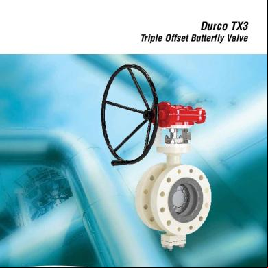
Flowserve Butterfly Valve 4746e
November 2019 45
Weco Butterfly Valve Actuators 364dv
November 2019 48
Butterfly Valve Equivalent Length 5886l
November 2019 119