Ds-1 Volumen 3 Adenda 7.pdf 284j
This document was ed by and they confirmed that they have the permission to share it. If you are author or own the copyright of this book, please report to us by using this report form. Report 3b7i
Overview 3e4r5l
& View Ds-1 Volumen 3 Adenda 7.pdf as PDF for free.
More details w3441
- Words: 40,649
- Pages: 84
Standard DS-1® Fourth Edition, Volume 3 - ADDENDUM 7 Applies to First, Second and Third Printing
In this Volume 3 - Addendum 7, the following items have been modified or added: Item Page Item Page ¶ 3.33.8.2 ....................................................... 23 ¶ 2.9.7............................................................... 2 ¶ 3.33.5.1.b-c ................................................. 23 Table 2.1.......................................................... 2 Figure 3.37.1.................................................. 24 Table 2.2 (note)................................................ 2 Table 3.7.1 .................................................... 25 ¶ 3.7.5.a ........................................................... 3 Table 3.7.2 .................................................... 26 ¶ 3.11.5.b ......................................................... 3 Table 3.7.3 .................................................... 30 ¶ 3.11.5.i .......................................................... 3 Table 3.7.4 .................................................... 34 ¶ 3.11.6 ............................................................ 4 Table 3.7.5 .................................................... 38 ¶ 3.11.6.b-c ...................................................... 4 Table 3.7.6 .................................................... 41 ¶ 3.11.6.d-e ..................................................... 5 Table 3.7.7 .................................................... 44 Figure 3.11.2 ................................................... 6 Table 3.7.8 .................................................... 47 Figures 3.11.3.a-c ........................................... 6 Table 3.7.9 .................................................... 49 ¶ 3.11.6.f .......................................................... 7 Table 3.7.10 .................................................. 51 ¶ 3.11.7.a ......................................................... 7 Table 3.7.11 .................................................. 51 ¶ 3.11.13........................................................... 8 Table 3.7.20 .................................................. 52 Figure 3.11.5.................................................... 9 Table 3.7.21 .................................................. 52 Figure 3.11.6.................................................... 9 Table 3.7.22 .................................................. 53 ¶ 3.11.14 ........................................................ 10 Table 3.7.23 .................................................. 54 Figure 3.11.7.................................................. 10 Table 3.7.24 .................................................. 55 Figure 3.11.8.................................................. 10 Table 3.7.25 .................................................. 56 ¶ 3.13.2.b-c .................................................... 11 Table 3.7.26 .................................................. 58 ¶ 3.13.5.a-b ................................................... 12 Table 3.7.27 .................................................. 62 ¶ 3.13.5.e ....................................................... 12 Table 3.7.28 .................................................. 63 ¶ 3.13.5.h ....................................................... 13 Table 3.7.29 .................................................. 67 ¶ 3.13.5.j ........................................................ 13 Table 3.7.30 .................................................. 70 Figure 3.13.2.................................................. 13 Table 3.9.2..................................................... 71 ¶ 3.13.6.b ....................................................... 14 Table 3.9.3..................................................... 71 ¶ 3.13.6.e ....................................................... 14 Table 3.9.4..................................................... 72 ¶ 3.13.6.h ....................................................... 14 Table 3.9.5..................................................... 72 ¶ 3.13.6.j ........................................................ 14 Table 3.9.6..................................................... 73 Figure 3.13.3.................................................. 15 Table 3.9.7..................................................... 73 ¶ 3.13.11.j ...................................................... 15 Table 3.9.9..................................................... 74 Figure 3.13.7.................................................. 15 Table 3.12...................................................... 75 ¶ 3.13.12 ........................................................ 16 ¶ 5.7.10 .......................................................... 82 ¶ 3.13.13 ........................................................ 18 ¶ 5.7.11 .......................................................... 82 Figure 3.13.10................................................ 18 ¶ 5.7.12 .......................................................... 82 Figure 3.13.11................................................ 18 ¶ 5.7.14 .......................................................... 82 ¶ 3.14.2.b ....................................................... 19 ¶ 5.7.15 .......................................................... 83 ¶ 3.14.5.a-b ................................................... 20 ¶ 5.7.16 .......................................................... 83 ¶ 3.14.5.e ....................................................... 20 ¶ 5.7.17 .......................................................... 83 ¶ 3.14.5.h ....................................................... 20 Appendix A.7.1.a-b ........................................ 84 ¶ 3.14.5.j ........................................................ 21 Appendix A.7.3............................................... 84 ¶ 3.14.6.b ....................................................... 21 ¶ 3.14.8 .......................................................... 21
Issue Date: February 7, 2018
Page 1
Standard DS-1® Fourth Edition, Volume 3 - ADDENDUM 7 Applies to First, Second and Third Printing Page 6 ¶ 2.9.7 CURRENT:
CHANGE TO: (Amended text is underlined) Recommended BSR Ranges
Recommended BSR Ranges
Drill Collar OD
Traditional Recommended BSR Range BSR Range
Drill Collar OD
< 6 inches 6 - 7 7/8 inches ≥ 8 inches
2.25-2.75 2.25-2.75 2.25-2.75
< 6 inches 2.25-2.75 6 to < 8 inches 2.25-2.75 ≥ 8 inches 2.25-2.75
1.8-2.5 2.25-2.75 2.5-3.2
Traditional Recommended BSR Range BSR Range 1.8-2.5 2.25-2.75 2.5-3.2
Page 16 Table 2.1 CURRENT: (text to be deleted is underlined)
CHANGE TO: (Amended text is underlined)
NAME OF METHOD:
WHAT IS DONE:
NAME OF METHOD:
WHAT IS DONE:
8
Visual Connection
Visual examination of connections, shoulders, and tool ts and profile check of threads, measurement of box swell
8
Visual Connection
Visual examination of connections, shoulders, and tool ts and profile check of threads, measurement of box swell and pin lead, and check for shoulder flatness
9
Dimensional 1
Measurement or Go-No-Go gaging of box OD, pin ID, shoulder width, tong space, box counterbore
9
Dimensional 1
Measurement or Go-No-Go gaging of box OD, pin ID, shoulder width, tong space
10 Dimensional 2
Dimensional 1 requirements plus measurement or Go-No-Go gaging of pin lead, counterbore depth, box counterbore, pin flat length, bevel diameter, seal width, and shoulder flatness
10 Dimensional 2
Dimensional 1 requirements plus measurement or Go-No-Go gaging of counterbore depth, box counterbore, pin flat length, bevel diameter
Page 19 Table 2.2, Note 1 CURRENT:
CHANGE TO: (Amended text is underlined)
Note 1: FLUT is recommended for drill pipe in lieu of EMI when either the measured wall thickness is greater than 0.400” or verification of wall thickness along the entire tube length is critical.
Note 1: FLUT is recommended for drill pipe in lieu of EMI when either the nominal wall thickness is greater than 0.500” or verification of wall thickness along the entire tube length is critical.
Issue Date: February 7, 2018
Page 2
Standard DS-1® Fourth Edition, Volume 3 - ADDENDUM 7 Applies to First, Second and Third Printing Page 35 ¶ 3.7.5.a CURRENT: (from Addendum 5)
CHANGE TO: (Amended text is underlined)
3.7.5 Standardization of Flux Leakage Equipment:
3.7.5 Standardization of Flux Leakage Equipment:
a. The equipment shall be adjusted to produce a common reference amplitude (minimum 10 mm for paper charts or a minimum of 80% of full screen height for digital display) from each detector when a hole is scanned. Signal to noise ratio shall be a minimum of 3 to 1.
a. The equipment shall be adjusted to produce a common reference amplitude (minimum 10 mm for paper charts or a minimum of 40% of full digital screen height) from each detector when a hole is scanned. Signal to noise ratio shall be a minimum of 3 to 1.
Page 42 ¶ 3.11.5.b CURRENT: (from Addendum 6) b. Thread Surfaces: For thread root and surface pitting criteria see A.7 in the Appendix for specific inspection requirements. Thread surfaces shall be free of other imperfections that appear to either penetrate below the thread root, occupy more than 1-1/2 inches in length along any thread helix or exceed 1/16 inch in depth or 1/8 inch in diameter. Raised protrusions must be removed with a hand file or “soft” (nonmetallic) buffing wheel. The thread profile shall be checked after any buffing or filing of the threads.
CHANGE TO: (Amended text is underlined) b. Thread Surfaces: For thread root pitting criteria see A.7 in the Appendix for specific inspection requirements. Other thread surfaces, such as thread crests, thread flanks, the box taper behind the last scratch with no stress-relief feature, and the area between the pin shoulder and the last scratch (i.e. pin-neck flats) with no stress-relief feature, shall be free of imperfections that appear to either penetrate below the thread root, occupy more than 1-1/2 inches in length along any thread helix or exceed 1/16 inch in depth or 1/8 inch in diameter. Raised protrusions must be removed with a hand file or “soft” (nonmetallic) buffing wheel. The thread profile shall be checked after any buffing or filing of the threads *Additional changes in A.7 are included in this Addendum 7.
Page 44 ¶ 3.11.5.i CURRENT: i. Box Taper: The box taper at the back of the box shall be visually inspected. All inner diameter tapers originating from a box thread shall be at an angle of 30° (+15°, -0°) from the centerline axis of the connection. No burr, lip or edge greater than the allowable angle tolerance is acceptable.
Issue Date: February 7, 2018
CHANGE TO: (Amended text is underlined) i. Box Taper: The box taper at the back of the box shall be visually inspected. All inner diameter tapers originating from a box thread shall be at an angle of 45 degrees maximum from the centerline axis of the connection. No burr, lip or edge greater than the allowable angle tolerance is acceptable.
Page 3
Standard DS-1® Fourth Edition, Volume 3 - ADDENDUM 7 Applies to First, Second and Third Printing Page 44 ¶ 3.11.6 CURRENT:
CHANGE TO: (Amended text is underlined)
NOTE: When conflicts arise between this specification and the manufacturer’s requirements, the manufacturer’s requirements shall apply.
NOTE: Damages include, but are not limited to, the following conditions: galls, nicks, washes, fins, dents, scratches, pits, or cuts. This does not include discoloration or other superficial anomalies that alter the appearance only. When conflicts arise between this specification and the manufacturer’s requirements, the manufacturer’s requirements shall apply.
Page 45 ¶ 3.11.6.b-c CURRENT: b. Primary Shoulder (Seal): The seal surfaces shall be free of raised metal or corrosion deposits detected visually or by rubbing a metal scale or fingernail across the surface. Any pitting or interruptions of the seal surface that are estimated to exceed 1/32 inch in depth or occupy more that 30% of the seal width at any given location are rejectable. No filing of the seal shoulders is permissible. c. Secondary Shoulder (Mechanical Stop): The Secondary Shoulder is not a sealing surface. Damage to this surface is not critical unless the damage interferes with the make-up, driftability, or torque capacity of the connection. Dents, scratches, and cuts do not affect this surface unless these exceed 1 inch in width and cause the connection to be rejected due to shortening of the shoulderto-shoulder length. Filing may be used to repair material protrusions, which extend from the face. Connection length readings shall not be taken in damaged areas.
Issue Date: February 7, 2018
CHANGE TO: (Amended text is underlined) b. Primary Shoulder (Seal): The seal surfaces shall be free of raised metal or corrosion deposits detected visually or by rubbing a metal scale or fingernail across the surface. Any pitting or interruptions of the seal surface that are estimated to exceed 1/32 inch in depth or cumulatively covers more than 1/3 of the radial width at any given location are rejectable. No filing of the seal shoulders is permissible. See figure 3.11.2 for examples of acceptable and rejectable damages. c. Secondary Shoulder (Mechanical Stop): The Secondary Shoulder is not a sealing surface. Damage to this surface is not critical unless the damage interferes with the make-up, driftability, or torque capacity of the connection. Dents, scratches, and cuts are not acceptable if they exceed 1 inch in length along the circumference or cause the connection to be rejected due to shortening of the shoulder-to-shoulder length. Any metal protrusion above the seal surface is not acceptable and shall be removed by filing, soft wheel, or other buffing method and protected by applying coating to the repaired areas. Connection length readings shall not be taken in damaged areas.
Page 4
Standard DS-1® Fourth Edition, Volume 3 - ADDENDUM 7 Applies to First, Second and Third Printing Page 45-46 ¶ 3.11.6.d-e CURRENT: d. Refacing: For HT®, XT™, uXT™, TT® , GPDS™, and uDS™, if refacing is necessary, the distance from the primary shoulder to the secondary shoulder must be maintained as required in the Dimensional 2 Inspection. Refacing limits are 1/32 inch on any one removal and 1/16 inch cumulatively. If existing benchmarks indicate that the shoulder has been refaced beyond the maximum, the connection shall be rejected.
CHANGE TO: (Amended text is underlined) d. Refacing: For HT™, XT™, uXT™, TT™ , GPDS™, and uGPDS™, if refacing is necessary, the distance from the primary shoulder to the secondary shoulder must be maintained as required in the Dimensional 2 Inspection. Refacing limits are 1/32 inch on any one removal and 1/16 inch cumulatively. If existing benchmarks indicate that the shoulder has been refaced beyond the maximum, the connection shall be rejected. • GPMark™ Benchmark: After refacing repair, a minimum length of 1/16 inch (.062”) shall remain on the box refacing benchmark, and 3/16 inch maximum (.188”) shall remain on the pin refacing benchmark. Rethreading is required if excess material is removed. See figure 3.11.3.a.
• H-Series™ Benchmark: After refacing repair, a minimum length of 1/16 inch (.062”) shall remain on the box refacing benchmark, and 3/16 inch maximum (.188”) shall remain on the pin refacing benchmark. Rethreading is required if excess material is removed. See figure 3.11.2. • Xmark™ Benchmarks: After refacing repair, a visible step on the benchmark shall remain on the primary shoulder. The step is a necessary indicator that a benchmark is still present. Rethreading is required if there is no visible benchmark. See figure 3.11.3. e. Threads: Thread flank surfaces shall be free of damage that exceeds 1/16 inch in depth or 1/8 inch in diameter. Thread roots shall be free of damage that extends below the thread root radius. Material that protrudes beyond the thread profile should be removed using a round cornered triangle hand file or soft buffing wheel.
NOTE: For XT™, uXT™, XT-M™, TT® and TT®-M connections, ...
• Xmark™ Benchmarks: After refacing repair, a visible step on the benchmark shall remain on the primary shoulder. The step is a necessary indicator that a benchmark is still present. Rethreading is required if there is no visible benchmark. See figure 3.11.3.b.
e. Threads: Thread flank surfaces shall be free of damage that exceeds 1/16 inch in depth or 1/8 inch in diameter/width. For damage that is not round, the 1/8 inch requirement applies to the width of the damage, and shall not apply to the length of the damage along the circumference. See figure 3.11.3.c. Material that protrudes beyond the thread profile shall be removed using a round cornered triangle hand file or soft buffing wheel. Any damage in the thread roots located within the Pit Free Zone designated on the “Field Inspection Dimensions” drawing, latest revision, is not acceptable. For thread roots outside the designated Pit Free Zone, damage that exceeds 1/32 inch in depth or 1/8 inch in diameter is not acceptable and shall be repaired by rethreading.
Issue Date: February 7, 2018
Machine refacing in a lathe is the preferred method. Portable field refacing units designed specifically for Grant Prideco connections are acceptable. A minimum of four measurements shall be taken when using a portable field refacing unit. The variability of face flatness and squareness is introduced and should be monitored. If any measurement is found to be outside the drawing limits, the connection shall be rejected.
NOTE: For XT™, uXT™, XT-M™, TT™ and TT-M™ connections, ...
Page 5
Standard DS-1® Fourth Edition, Volume 3 - ADDENDUM 7 Applies to First, Second and Third Printing
Page 45 Replace current with new Figure 3.11.2, 3.11.3.a, and 3.11.3.c (New) NEW:
NEW:
0.125" (1/8")
0.125" (1/8") New Benchmark
0.031" (1/32")
0.188" (3/16")
0.031" (1/32")
0.063" (1/16")
Max Removed per Reface
Max Reface
Figure 3.11.3.a GPMark™ Benchmarks. CHANGE: Renumber 3.11.3 to 3.11.3.b 0.063" (1/16")
0.063" (1/16")
Acceptable Damage
Ew + Fw ≤
W 3
Gw + I w ≤
W 3
(Hw is not loated at the same radial position as Gw and Iw, and is therefore not added to the total width at this location)
0.031" (1/32")
0.031" (1/32")
0.063" (1/16")
0.063" (1/16")
Rejectable Damage
Aw >
W 3
New Benchmark
Single Reface
Max Reface (with visible step)
Figure 3.11.3.b Xmark™ Benchmarks.
Bw + Cw + Dw >
W 3
NEW:
Figure 3.11.2 Acceptable and rejectable seal damage.
Figure 3.11.3.c Dimensions of damage on thread flanks. Issue Date: February 7, 2018
Page 6
Standard DS-1® Fourth Edition, Volume 3 - ADDENDUM 7 Applies to First, Second and Third Printing Page 46 ¶ 3.11.6.f CURRENT: f. Thread Profile: The thread profile shall be verified along the full length of complete threads in two locations at least 90° apart. The profile gage should mesh evenly in the threads and show normal . If the profile gage does not mesh evenly in the threads, lead measurements shall be taken.
CHANGE TO: (Amended text is underlined) f. Thread Profile: The thread profile shall be verified along the full length of complete threads in two locations at least 90° apart. The profile gage shall mesh evenly in the threads and show normal . If the profile gage does not mesh evenly in the threads, lead measurements shall be taken.
Page 46 ¶ 3.11.7.a CURRENT: a. 15° Seal: The 15° metal-to-metal sealing surfaces are allowed to contain round pit type defects in the area of the seal surface up to 1/32 inch in diameter and not exceeding 1/32 inch in depth. Multiple pits of this type are acceptable provided there is at least 1-inch circumferential separation between them. Circumferential lines or marks are acceptable in this surface provided they cannot be detected by rubbing a fingernail across the surface. The following “Pin Seal” and “Box Seal” diagrams (figure 3.11.4) show areas of the seal that may contain damage exceeding that previously stated in this procedure. The area of the pin seal within 0.060 inch of the minor pin nose diameter is a not- surface and damage in this area does not affect sealing. The area on the pin seal within 0.060 inch of the major pin nose diameter may also contain damage or pitting. Damages and pitting within these two areas of the pin seal are permissible provided the balance of the pin seal surface area meets the requirements of this procedure. Similarly, the area on the box seal within 0.188 inch of the major box cylinder diameter contains the non- portion of the box seal and that portion of the seal that corresponds to the first 0.060 inch of the pin seal. Damage and pitting within this area of the box seal are permissible provided the balance of the box seal surface area meets the requirements of this section.
Issue Date: February 7, 2018
CHANGE TO: (Amended text is underlined) a. 15° Seal: The 15° metal-to-metal sealing surfaces are allowed to contain non-circumferential damage that is less than or equal to 1/32 inch in length, width, diameter or depth. Multiple pits of this type are acceptable provided there is at least 1-inch circumferential separation between them. Circumferential lines or marks are acceptable in this surface provided they cannot be detected by rubbing a fingernail across the surface. The following “Pin Seal” and “Box Seal” diagrams (figure 3.11.4) show areas of the seal that may contain damage exceeding that previously stated in this procedure. The area of the pin seal within 0.060 inch of the minor pin nose diameter is a not- surface and damage in this area does not affect sealing. The area on the pin seal within 0.060 inch of the major pin nose diameter may also contain damage or pitting. Damages and pitting within these two areas of the pin seal are permissible provided the balance of the pin seal surface area meets the requirements of this procedure. Similarly, the area on the box seal within 0.188 inch of the major box cylinder diameter contains the non portion of the box seal and that portion of the seal that corresponds to the first 0.060 inch of the pin seal. Damage and pitting within this area of the box seal are permissible provided the balance of the box seal surface area meets the requirements of this section. Any metal protrusion above the seal surface is not acceptable. Filing is not permitted on any area of the radial metal-to-metal seal.
Page 7
Standard DS-1® Fourth Edition, Volume 3 - ADDENDUM 7 Applies to First, Second and Third Printing Page 49a ¶ 3.11.13 - Add new section NEW: 3.11.13 Delta™ Connections: In addition to the requirements of paragraph 3.11.4, Grant Prideco Delta™ connections shall meet the following requirements. NOTE: Damages include, but are not limited to, the following conditions: galls, nicks, washes, fins, dents, scratches, pits, or cuts. This does not include discoloration or other superficial anomalies that alter the appearance only. When conflicts arise between this specification and the manufacturer’s requirements, the manufacturer’s requirements shall apply. a. Preparation: All thread, make-up shoulder and seal surfaces shall be cleaned sufficiently to allow for visual inspection. The starting threads of the pin and box connections should be cleaned using a “soft wheel” or other buffing method. b. Primary Shoulder (Seal): The seal surface shall be free of galls, nicks, washes, fins, or other conditions for which the damage exceeds 3/64 inch in depth, cumulatively covers more than 1/3 of the radial width of the seal surface, or raised metal protrudes above the seal surface (Filing on the primary makeup shoulder is not permitted). See figure 3.11.2 for examples of acceptable and rejectable damages. c. Secondary Shoulder (Mechanical Stop): The Secondary Shoulder is not a sealing surface. Damage to this surface is not critical unless the damage interferes with the make-up, driftability, or torque capacity of the connection. Dents, scratches, and cuts do not affect this surface unless the damage around the circumference prevents the connection length from being accurately measured at two locations approximately 180 degrees apart or any raised metal protruding above the seal surface that cannot be removed by filing, soft wheel, or other buffing method (Any repaired areas shall be protected by applying an acceptable coating). d. Refacing: Repair by refacing may only be used to attempt to repair shoulder damage less than or equal to 3/64 inch in depth, and/or connection length discrepancies that are less than 1/32 inch out of specification. • As typical of the rotary shoulder connection reface process, a maximum of 1/32 inch of material may be removed from the primary make-up shoulder during each refacing operation, after which the t shall be placed back into service prior to performing any additional refacing repair.
Issue Date: February 7, 2018
• The cumulative total material removal from the primary make-up shoulder for all refacing operations shall not exceed 3/32 inch before rethreading is required. • Repair by refacing methods shall only remove sufficient material to repair the damage. However, when damage is less than 1/32 inch deep, all damage shall be removed from the primary make-up shoulder. • After the maximum reface allowance is met, any remaining damage on the primary make-up shoulder shall not be deeper than 1/64 inch and shall meet all other requirements of this procedure. • If the connection cannot be brought back within the acceptable limits outlined in this procedure without removing more than 1/32 inch of material from the primary shoulder, then rethreading shall be required. • Both the primary make-up shoulder and secondary make-up shoulder shall be skimmed/machined during a refacing operation for all double shoulder connections. • Machine refacing in a lathe is the preferred method. • If the portable field refacing unit method is used, the variability of face flatness and squareness is introduced and shall be monitored by taking the connection length measurements in a minimum of four locations, equally spaced around the circumference. Each measurement shall be within the limits of the “Field Inspection Dimensions” drawing, latest revision. • GPMark™ + Benchmark: After refacing repair, a minimum length of 1/16 inch (.063”) shall remain on the box refacing benchmark, and 3/16 inch maximum (.188”) shall remain on the pin refacing benchmark. Rethreading is required if excess material is removed. See figure 3.11.5 • Xmark™ + Benchmarks: After refacing repair, a visible step on the benchmark shall remain on the primary shoulder. The step is a necessary indicator that a benchmark is still present. Rethreading is required if there is no visible benchmark. See figure 3.11.6. e. Threads: Thread surfaces shall be free of any raised metal protruding above the thread surface that cannot be removed by filing, soft wheel, or other buffing method (Filing is not permitted in the
Page 8
Standard DS-1® Fourth Edition, Volume 3 - ADDENDUM 7 Applies to First, Second and Third Printing Page 49a ¶ 3.11.13 - Add new section (continued) NEW: 0.094" (3/32")
0.156" (5/32")
0.031" (1/32")
0.031" (1/32")
New Benchmark
0.188" (3/16")
0.063" (1/16")
Max Removed per Reface
Max Reface
Figure 3.11.5 Refacing with the GPmark™ + Benchmark for Delta™ connections. 0.094" (3/32")
0.094" (3/32")
New Benchmark
0.031" (1/32")
0.031" (1/32")
0.094" (3/32")
f. Thread Profile: The thread profile shall be verified along the length of the full form threads in two locations at least 90 degrees apart. The profile gauge shall mesh evenly in the threads and show normal . If the profile gauge does not mesh in the threads, lead measurements shall be taken. g. Lead: If the profile gage indicates that thread stretch has occurred, lead shall be measured over a 2-inch interval. Thread stretch shall not exceed 0.006 inch over the 2-inch length. Connections failing this inspection should be repaired by rethreading.
0.094" (3/32")
Max Removed per Reface
thread roots.) Any repaired areas shall be protected by applying an acceptable coating. Thread flank surfaces shall be free of damage that exceeds 1/16 inch in depth or 1/8 inch in diameter/width. For damage that is not round, the 1/8 inch requirement applies to the width of the damage, and shall not apply to the length of the damage along the circumference. See figure 3.11.3.c. Thread roots within the Pit Free Zone designated on the “Field Inspection Dimension” drawing, latest revision, shall be free of all damage. For thread roots outside of the designated Pit Free Zone, damage shall not exceeds 1/32 inch in depth or 1/8 inch in diameter.
Max Reface
Figure 3.11.6 Refacing with the Xmark™ + Benchmark for Delta™ connections.
h. Coating: Threads and shoulders that are repaired by filing or refacing shall be protected by hot phosphate coating, or by using copper sulfate or other commercially available effective surface etchant products suitable for rotary shoulder connections. All rethreaded connections shall be protected by hot phosphate coating. i. Dimensional: Dimensional 2 (Section 3.13.12) is required for drill pipe connections and Dimensional 3 (Section 3.14.8) is required for HWDP, drill collar and sub connections.
Issue Date: February 7, 2018
Page 9
Standard DS-1® Fourth Edition, Volume 3 - ADDENDUM 7 Applies to First, Second and Third Printing Page 49b ¶ 3.11.14 - Add new section NEW: 3.11.14 VAM® X-Force™: In addition to the Visual Connection requirements of paragraph 3.11.4, VAM® X-Force™ (VF) connections shall meet the following requirements.
b. Bevel Width: An approximate 45 degree OD bevel at least 1/32 inch wide shall be present for the full circumference on both pin and box.
external shoulders to check whether the connector can be re-faced or not. As shown in figure 3.11.7, pin benchmark is a groove cut inside the external shoulder that has the same depth as allowed refacing depth (1/16 inch). When the pin benchmark is no longer visible, it means that the connection cannot be re-faced anymore. On the box end, as shown in figure 3.11.8, the benchmark is a recess on the counter-bore diameter of the external shoulder. This benchmark has twice the depth of allowed refacing depth. When box benchmark depth is equal to or smaller than 1/16 inch, the box connection cannot be re-faced anymore. Measurement of box benchmark depth is also an indicator of how much re-facing was already carried out on the box part.
c. Box Swell: A straightedge shall be placed along the longitudinal axis of the box tool t. If a visible gap exists between the straightedge and the tool t, the OD must be measured using calipers. Compare the OD at the bevel to the OD 2 inches, ±1/2 inch away from the bevel. If the OD at the bevel is greater by 1/32 inch or more, the connection shall be rejected.
g. Threads: Thread surfaces shall be free of damage that exceeds 1/16 inch in depth or 1/8 inch in diameter or that occupy more than 1-1/2 inch in length along the thread helix. Thread roots shall be free of damage that extends below the thread root radius. Material that protrudes beyond the thread profile should be removed using a round cornered triangle hand file or soft buffing wheel.
NOTE: When conflicts arise between this specification and the manufacturer’s requirements, the manufacturer’s requirements shall apply. a. Preparation: All thread, make-up shoulder and seal surfaces shall be cleaned sufficiently to allow for visual inspection.
d. Primary Shoulder (Seal): Any pitting, interruptions, galls, nicks, washes, fins or other conditions on the seal surface that are estimated to exceed 1/32 inch in depth or occupy more that 30% of the seal width at any given location are rejectable. No filing of the seal shoulders is permissible. e. Secondary Shoulder (Mechanical Stop): The secondary shoulder is not a seal. This shoulder must be free of raised metal or other imperfections that could prevent proper make-up, driftability or cause galling. Secondary shoulder damage can be repaired with a hand file and should be used to remove protruding metal. f. Refacing: If refacing is necessary, the distance from the primary shoulder to the secondary shoulder must be maintained as required in the Dimensional 2 Inspection. Shoulder refacing must be performed in a machine repair shop. Refacing limits are 1/32 inch on any one removal and 1/16 inch cumulatively. If existing benchmarks indicate that the shoulder has been refaced beyond the maximum, the connection shall be rejected. Drill pipe machined with VAM® X-Force™ design have benchmark on pin and box
Issue Date: February 7, 2018
0.0625" NEW
Figure 3.11.7 Pin end benchmark.
0.125" NEW
Figure 3.11.8 Box end benchmark.
Page 10
Standard DS-1® Fourth Edition, Volume 3 - ADDENDUM 7 Applies to First, Second and Third Printing Page 49b ¶ 3.11.14 - Add new section (continued) NEW: h. Thread Profile: The thread profile shall be verified along the full length of complete threads in two locations at least 90 degrees apart. The profile gage should mesh evenly in the threads and show normal . If the profile gage does not mesh evenly in the threads, lead measurements shall be taken. i. Lead: If the profile gage indicates that thread stretch has occurred, lead shall be measured over a 2-inch interval. Thread stretch shall not exceed 0.006 inch over the 2-inch length. j. Coating: VAM® X-Force™ should always have a phosphate coating (Mn or Zn) on both the pin and
box thread and shoulder areas. If this coating is slightly worn in some areas it is acceptable, however if the coating is removed completely or if re-facing has been carried out, the connector requires recoating with phosphate or with a Molybdenum Disulfide (MoS2) repair kit (like Molykote® spray products). k. Box Counterbore: The box counterbore radius shall be free of any sharp edged defects caused by poor handling or stabbing. Such defects must be removed by grinding prior to re-using the connection.
Page 50 ¶ 3.13.2.b-c CURRENT:
CHANGE TO: (Amended text is underlined)
b. Grant Prideco HI TORQUE™, eXtreme™ Torque, uXT™, eXtreme™ Torque-M, TurboTorque™, TurboTorque-M™, Grant Prideco™ Double Shoulder and uPDS™ Connections: In addtion... ... Dimensions provided in tables 3.7.2 - 3.7.9 and 3.7.20 - 3.7.24 are considered equivalent to the dimensions provided in Grant Prideco field inspection drawings at the time of this document’s release. Responsibility...
b. Grant Prideco HI TORQUE™, eXtreme™ Torque, uXT™, eXtreme™ Torque-M, TurboTorque™, TurboTorque-M™, Grant Prideco™ Double Shoulder uGPDS™ and Delta™ Connections: In addtion... ... Dimensions provided in tables 3.7.2 - 3.7.9 , 3.7.20 - 3.7.24, 3.7.28 and 3.7.30 are considered equivalent to the dimensions provided in Grant Prideco field inspection drawings at the time of this document’s release. Responsibility...
c. VAM Drilling VX, EIS, CDS and TM2 Connections: In addition to...
c. VAM VX, EIS, CDS, TM2 and VF Connections: In addition to...
Issue Date: February 7, 2018
Page 11
Standard DS-1® Fourth Edition, Volume 3 - ADDENDUM 7 Applies to First, Second and Third Printing Page 53 ¶ 3.13.5.a-b CURRENT:
CHANGE TO: (Amended text is underlined)
a. Box Outside Diameter (OD): For NOV Grant Prideco HI TORQUE®, eXtreme™ Torque, uXT™ and eXtreme™ Torque-M connections, the OD of the tool t box shall be measured at a distance of 2 inches ±1/4 inch from the primary make-up shoulder. Measurements shall be taken around the circumference to determine the minimum diameter. This minimum box diameter shall meet the requirements in table 3.7.2 - 3.7.4, 3.7.8, 3.7.20 - 3.7.21, or 3.7.24, as applicable. For NOV Grant Prideco TurboTorque and TurboTorque ®-M connections, the OD of the tool t box shall be measured at a distance of 5/8 inch to 7/8 inch from the primary make-up shoulder. Measurements shall be taken around the circumference to determine the minimum diameter. This minimum box diameter shall meet the requirements in table 3.7.6 - 3.7.7 or 3.7.223.7.23, as applicable. ®
b. Pin Inside Diameter (ID): The pin ID shall be measured under the last thread nearest the shoulder (±1/4 inch) and shall meet the requirements in table 3.7.2 - 3.7.8 or 3.7.20 - 3.7.24, as applicable.
a. Box Outside Diameter (OD): For Grant Prideco™ HI TORQUE™ and eXtreme™ Torque-M connections, the OD of the tool t box shall be measured at a distance of 2 inches ±1/4 inch from the primary make-up shoulder. Measurements shall be taken around the circumference to determine the minimum diameter. This minimum box diameter shall meet the requirements in table 3.7.2, 3.7.4, or 3.7.20, as applicable.
For Grant Prideco™ eXtreme™ Torque and uXT™ sizes 43 and smaller (e.g. XT43), the OD of the tool t box shall be measured at a distance of 5/8 inches ± 1/4 inch from the primary make-up shoulder. For sizes 46 and larger, the OD of the tool t box shall be measured at a distance of 2 inches ± 1/4 inch from the primary make-up shoulder. Measurements shall be taken around the circumference to determine the minimum diameter. This minimum box diameter shall meet the requirements in table 3.7.3, 3.7.8, 3.7.21, or 3.7.24, as applicable.
For Grant Prideco™ TurboTorque™ and TurboTorque-M™ connections, the OD of the tool t box shall be measured at a distance of 5/8 inch to 7/8 inch from the primary make-up shoulder. Measurements shall be taken around the circumference to determine the minimum diameter. This minimum box diameter shall meet the requirements in table 3.7.6 - 3.7.7 or 3.7.223.7.23, as applicable. b. Pin Inside Diameter (ID): The pin ID shall be measured under the last thread nearest to the shoulder (±1/4 inch) and referenced against the values in table 3.7.2 - 3.7.8 or 3.7.20 - 3.7.24, as applicable. The pin ID is used to define other inspection dimensions.
Page 53 ¶ 3.13.5.e CURRENT: e. Box Counterbore Diameter: The box counterbore diameter shall be measured and shall meet the requirements shown in table 3.7.2 - 3.7.8 or 3.7.20 - 3.7.24, as applicable. This dimension is not used to determine acceptance or rejection, but to test for box swell and the need to connection length.
Issue Date: February 7, 2018
CHANGE TO: (Amended text is underlined) e. Box Counterbore Diameter: The box counterbore diameter shall be measured at two locations 90 degrees apart and shall meet the requirements shown in table 3.7.2 - 3.7.8 or 3.7.20 - 3.7.24, as applicable. If the diameter exceeds these limits, the connection shall be repaired by rethreading.
Page 12
Standard DS-1® Fourth Edition, Volume 3 - ADDENDUM 7 Applies to First, Second and Third Printing Page 53 ¶ 3.13.5.h CURRENT:
CHANGE TO: (Amended text is underlined)
h. Pin Nose Diameter: For HT®, XT™, uXT™, TT® connections, the outside diameter of the pin nose shall be measured and shall meet the requirements shown in table 3.7.2, 3.7.3, 3.7.6, 3.7.8, 3.7.20, 3.7.21, 3.7.22 or 3.7.24, as applicable. This is not required for XT-M™ or TT-M® connections. This dimension is not used to determine acceptance or rejection, but to test for pin nose swell and the need to connection length.
h. Pin Nose Diameter: For HT™, XT™, uXT™, TT™ connections, the outside diameter of the pin nose shall be measured at two locations 90 degrees apart and shall meet the requirements shown in table 3.7.2, 3.7.3, 3.7.6, 3.7.8, 3.7.20, 3.7.21, 3.7.22 or 3.7.24, as applicable. Nonconforming connections shall be rethreaded. This dimension is not used to determine acceptance or rejection for XT-M™ or TT-M™ connections, but to test for pin nose swell and the need to connection length.
Page 53 ¶ 3.13.5.j CURRENT:
CHANGE TO: (Amended text is underlined)
j. Pin Cylinder Diameter: The pin cylinder diameter shall be measured and shall meet the requirements shown in table 3.7.2 - 3.7.8 or 3.7.20 - 3.7.24, as applicable.
j. Pin Cylinder Diameter: This is not required for Grant Prideco connections.
Page 52 Figure 3.13.2 CHANGE TO: (Delete “J” from figure and legend) G I C
H
B
A
E F
DP
DB
A B C D B D P E F G H
DETAIL OF HT™, XT™, uXT™ AND TT™
DETAIL OF XT-M™ AND TT-M™
I
BOX OUTSIDE DIAMETER PIN INSIDE DIAMETER BOX COUNTERBORE WALL BOX TONG SPACE PIN TONG SPACE BOX COUNTERBORE DIAMETER BEVEL DIAMETER BOX CONNECTION LENGTH PIN NOSE DIAMETER (DOES NOT APPLY TO XT-M™ AND TT-M™) PIN CONNECTION LENGTH
VOLUME 3 Figure 3.13.2 Tool t dimensions for Grant Prideco™ HI TORQUE™, eXtreme™ Torque, uXT™, XT-M™, TurboTorque™, TurboTorque-M™ and Delta™ Connections.
Figure 3.13.2 Tool t dimensions for Grant Prideco™ HI TORQUE™, eXtreme™ Torque, uXT™, XT-M™, REDRAWN JAN-20-2018TurboTorque-M™ and Delta™ Connections. TurboTorque™, Issue Date: February 7, 2018
Page 13
Standard DS-1® Fourth Edition, Volume 3 - ADDENDUM 7 Applies to First, Second and Third Printing Page 55 ¶ 3.13.6.b CURRENT: b. Pin Inside Diameter (ID): The pin ID shall be measured under the last thread nearest the shoulder (± 1/4 inch) and shall meet the requirements in table 3.7.5 or 3.7.9, as applicable.
CHANGE TO: (Amended text is underlined) b. Pin Inside Diameter (ID): The pin ID shall be measured under the last thread nearest to the shoulder (±1/4 inch) and referenced against the values in table 3.7.5 or 3.7.9, as applicable. The pin ID is used to define other inspection dimensions.
Page 55 ¶ 3.13.6.e CURRENT: e. Box Counterbore Diameter: The box counterbore diameter shall be measured and shall meet the requirements shown in table 3.7.5 or 3.7.9, as applicable. This dimension is not used to determine acceptance or rejection, but to test for box swell and the need to connection length.
CHANGE TO: (Amended text is underlined) e. Box Counterbore Diameter: The box counterbore diameter shall be measured at two locations 90 degrees apart and shall meet the requirements shown in table 3.7.5 or 3.7.9, as applicable. If the diameter exceeds these limits, the connection shall be repaired by rethreading.
Page 55 ¶ 3.13.6.h CURRENT: h. Pin Nose Diameter: The outside diameter of the pin nose shall be measured and shall meet the requirements shown in table 3.7.5 or 3.7.9, as applicable. This dimension is not used to determine acceptance or rejection, but to test for pin nose swell and the need to connection length.
CHANGE TO: (Amended text is underlined) h. Pin Nose Diameter: The outside diameter of the pin nose shall be measured at two locations 90 degrees apart and shall meet the requirements shown in table 3.7.5 or 3.7.9, as applicable.
Page 55 ¶ 3.13.6.j CURRENT: j. Pin Cylinder Diameter: The pin cylinder diameter shall be measured and shall meet the requirements shown in table 3.7.5 or 3.7.9, as applicable.
Issue Date: February 7, 2018
CHANGE TO: (Amended text is underlined) j. Pin Cylinder Diameter: This is not required for Grant Prideco connections.
Page 14
Standard DS-1® Fourth Edition, Volume 3 - ADDENDUM 7 Applies to First, Second and Third Printing Page 54 Figure 3.13.3 CHANGE TO: (Delete “J” from figure and legend) G I
C
H
B
A
E F
D P1
D B1 D B2
D P2
A BOX OUTSIDE DIAMETER DP1 PIN TONG SPACE (VAM CONNECTIONS) B PIN INSIDE DIAMETER DP2 PIN TONG SPACE (GPDS & uGPDS) C BOX SHOULDER WIDTH (VAM CONNECTIONS) E BOX COUNTERBORE DIAMETER BOX COUNTERBORE WALL (GPDS & uGPDS) F BEVEL DIAMETER VOLUME 3 DB1 BOX TONG SPACE (VAM CONNECTIONS) G BOX CONNECTION LENGTH Figure 3.13.3 ToolDt for Grant Prideco™ Double Shoulder, uGPDS™, VAM® Express™, EIS®,NOSE VAM® CDS, VAM TorqMaster 2™, and dimensions BOX TONG SPACE (GPDS & uGPDS) H VAMPIN DIAMETER B2 VAM® X-Force™ Connections. I PIN CONNECTION LENGTH REDRAWN JAN-20-2018
Figure 3.13.3 Tool t dimensions for Grant Prideco™ Double Shoulder, uGPDS™, VAM® Express™, VAM EIS®, VAM® CDS, VAM TorqMaster 2™, and VAM® X-Force™ Connections. Page 59b (from Addendum 6) ¶ 3.13.11.j CURRENT:
CHANGE TO: (Amended text is underlined)
j. Pin Cylindrical Diameter: The pin cylindrical diameter shall be measured as shown in figure 3.13.7. The pin cylindrical diameter must meet the requirements in tables 3.7.25 - 3.7.27, as applicable.
j. Pin Cylindrical Diameter: This is not required for DP-Master connections.
Page 59b (from Addendum 6) Figure 3.13.7 CHANGE TO: (Delete “J” from figure and legend) G I
C
H
B
A
E F
DP
DB A
BOX OUTSIDE DIAMETER
D DP
BOX TONG SPACE PIN TONG SPACE
PIN INSIDE DIAMETER VOLUMEB 3Figure 3.13.7 t dimensions for DPM-DS, WALL DPM-MT and DPM High Torque PAC connections. C Tool BOX COUNTERBORE REDRAWN BJAN-20-2018
E F G H I
BOX COUNTERBORE DIAMETER BEVEL DIAMETER BOX CONNECTION LENGTH PIN NOSE DIAMETER PIN CONNECTION LENGTH
Figure 3.13.7 Tool t dimensions for DPM-DS, DPM-MT and DPM High Torque PAC connections. Issue Date: February 7, 2018
Page 15
Standard DS-1® Fourth Edition, Volume 3 - ADDENDUM 7 Applies to First, Second and Third Printing Page 59c ¶ 3.13.12 - Add new section NEW: 3.13.12 Procedure and Acceptance Criteria for Grant Prideco™ Delta™ Connections: These features are illustrated in figure 3.13.2. In addition to the Visual Connection requirements of 3.11.6, the Grant Prideco™ Delta™ connections shall meet the following requirements. NOTE: When conflicts arise between this specification and the manufacturer’s requirements, the manufacturer’s requirements shall apply. a. Box Outside Diameter (OD): The OD of the tool t box shall be measured at a distance 5/8 inch (±1/4 inch) from the primary make-up shoulder. Measurements shall be taken around the circumference to determine the minimum diameter. This minimum box diameter shall meet the requirements in table 3.7.28 or 3.7.30, as applicable. b. Pin Inside Diameter (ID): The pin ID shall be measured under the last thread nearest to the shoulder (±1/4 inch) and referenced against the values in table 3.7.28 or 3.7.30, as applicable. The pin ID is used to define other inspection dimensions. c. Box Counterbore (CBore) Wall Thickness: The box CBore wall thickness shall be measured by placing the straightedge longitudinally along the tool t, extending past the shoulder surface, and then measuring the wall thickness from this extension to the counterbore. The CBore wall thickness shall be measured at its point of minimum thickness. Any reading that does not meet the minimum CBore wall thickness requirement in table 3.7.28 or 3.7.30, as applicable, shall cause the tool t to be rejected. d. Tong Space: Box and pin tong space (including the OD bevel) shall meet the requirements of table 3.7.28 or 3.7.30, as applicable. Tong space measurements on hardfaced components shall be made from the primary shoulder face to the edge of the hardfacing. e. Box Counterbore Diameter: The box counterbore diameter shall be measured at two locations 90 degrees apart. The diameters shall meet the requirements in table 3.7.28 or 3.7.30, as applicable. If the limits are exceeded, the connection shall be rethreaded. f. Bevel Diameter: The bevel diameter on both the box and pin shall be measured and shall meet the requirements shown in table 3.7.28 or 3.7.30, as applicable.
Issue Date: February 7, 2018
g. Box Connection Length: The distance between the primary and secondary make-up shoulders shall be measured in two locations, 180 degrees apart, and free from mechanical damage. Measurements shall not be taken in areas where surface condition prevents accurate measurements. This distance shall meet the requirements of table 3.7.28 or 3.7.30, as applicable. Refer to 3.13.5.l for repair of connection length non-conformances. h. Pin Nose Diameter: The outside diameter of the pin nose shall be measured at two locations 90 degrees apart and shall meet the requirements shown in table 3.7.28 or 3.7.30, as applicable. If the diameter exceeds the specified limit, the connection shall be repaired by rethreading. i. Pin Connection Length: The distance between the primary and secondary make-up shoulders shall be measured in two locations, 180 degrees apart, and free from mechanical damage. Measurements shall not be taken in areas where surface condition prevents accurate measurements. This distance shall meet the requirements of table 3.7.28 or 3.7.30, as applicable. Refer to 3.13.5.l for repair of connection length non-conformances. j. Pin Cylinder Diameter: This is not required for Delta™ connections. k. Thread Compound and Protectors: Acceptable connections shall be coated with an API Tool t Compound over all thread and shoulder surfaces including the end of the pin. A copper-based thread compound is recommended. Thread protectors shall be applied and secured with approximately 50 to 100 ft-lbs of torque. The thread protectors shall be free of debris. If additional inspection of the threads or shoulders will be performed prior to pipe movement, application of thread compound and protectors may be postponed until completion of the additional inspection. l. Refacing: Repair by refacing may only be used to attempt to repair shoulder damage less than or equal to 3/64 inch in depth, and/or connection length discrepancies that are less than 1/32 inch out of specification. • As typical of the rotary shoulder connection reface process, a maximum of 1/32 inch of material may be removed from the primary make-up shoulder during each refacing operation, after which the
Page 16
Standard DS-1® Fourth Edition, Volume 3 - ADDENDUM 7 Applies to First, Second and Third Printing Page 59c ¶ 3.13.12 - Add new section (continued) NEW: t shall be placed back into service prior to performing any additional refacing repair. • The cumulative total material removal from the primary make-up shoulder for all refacing operations shall not exceed 3/32 inch before rethreading is required. • Repair by refacing methods shall only remove sufficient material to repair the damage. However, when damage is less than 1/32 inch deep, all damage shall be removed from the primary make-up shoulder. • After the maximum reface allowance is met, any remaining damage on the primary make-up shoulder shall not be deeper than 1/64 inch and shall meet all other requirements of this procedure. • If the connection cannot be brought back within the acceptable limits outlined in this procedure without removing more than 1/32 inch of material from the primary shoulder, then rethreading shall be required. • Both the primary make-up shoulder and secondary make-up shoulder shall be skimmed/machined during a refacing operation for all double shoulder connections. • Machine refacing in a lathe is the preferred method. • If the portable field refacing unit method is used, the variability of face flatness and squareness is introduced and shall be monitored by taking the connection length measurements in a minimum of four locations, equally spaced around the cir-
Issue Date: February 7, 2018
cumference. Each measurement shall be within the limits of the “Field Inspection Dimensions” drawing, latest revision. • GPMark™ + Benchmark: After refacing repair, a minimum length of 1/16 inch (.063”) shall remain on the box refacing benchmark, and 3/16 inch maximum (.188”) shall remain on the pin refacing benchmark. Rethreading is required if excess material is removed. See figure 3.11.5. • Xmark™ + Benchmarks: After refacing repair, a visible step on the benchmark shall remain on the primary shoulder. The step is a necessary indicator that a benchmark is still present. Rethreading is required if there is no visible benchmark. See figure 3.11.6. m. Rethreading: This method shall be used to repair connections that fail to meet the requirements stipulated in this inspection procedure after field repair is completed. Performance of this operation requires cropping the connection behind any fatigue crack. Complete removal of the thread profile is not necessary if the connection has no fatigue cracks and if sufficient material can be removed to comply with the NEW product requirements. In this case, the connection does not have to be “reblanked,” however all torque shoulders, seal surfaces and thread elements must be machined to 100% “bright metal”. This is not necessary for cylindrical diameters. After rethreading, the connection must be phosphate coated. Copper sulfate is not an acceptable substitute for phosphate coating on rethreaded connections.
Page 17
Standard DS-1® Fourth Edition, Volume 3 - ADDENDUM 7 Applies to First, Second and Third Printing Page 59d ¶ 3.13.13 - Add new section NEW: 3.13.13 Procedure and Acceptance Criteria for VAM® X-Force™ Connections: The connections may be abbreviated as VF. These features are illustrated in figure 3.13.3. In addition to the Visual Connection requirements of 3.11.14, VAM VF connections shall meet the following requirements. NOTE: When conflicts arise between this specification and the manufacturer’s requirements, the manufacturer’s requirements shall apply. a. Tool t Box Outside Diameter (OD): The OD of the tool t box shall be measured 2 inches ± 1/4 inch from the primary shoulder. Measurements shall be taken around the circumference to determine the minimum diameter. This minimum box diameter shall meet the requirements in table 3.7.29. b. Pin Inside Diameter (ID): The pin ID shall be measured under the last thread nearest the shoulder (± 1/4 inch) and shall meet the requirements in table 3.7.29. c. Box Shoulder Width: The box shoulder width shall be measured by placing the straightedge longitudinally along the tool t, extending past the shoulder surface, and then measuring the shoulder thickness from this extension to the counterbore. The shoulder width shall be measured at its point of minimum thickness. Any reading that does not meet the minimum shoulder width requirement in table 3.7.29 shall cause the tool t to be rejected.
Figure 3.13.10 Two Methods of Box Connection Length Inspection.
Issue Date: February 7, 2018
d. Tong Space: Box and pin tong space shall meet the requirements of table 3.7.29. Tong space measurements on hardfaced components shall be made from the bevel to the edge of the hardfacing. e. Box Counterbore Diameter: The box counterbore diameter shall be measured and shall meet the requirements shown in table 3.7.29. Since the box benchmark is a recess on the counter bore diameter of the external shoulder, be sure to measure the box end counter bore diameter and not the box benchmark diameter. f. Bevel Diameter: The bevel diameter on both the box and pin shall be measured and shall meet the requirements shown in table 3.7.29. g. Box Connection Length: The distance between the primary and secondary make-up shoulders shall be measured in two locations, 90 degrees apart, and free from mechanical damage. This distance shall meet the requirements of table 3.7.29. If the connection length exceeds the specified criteria, repair may be made by refacing the primary shoulder. If the connection length is less than the specified criteria, refacing the secondary shoulder may be adequate to repair the connection. Refacing limits are the same as that performed for damaged shoulder faces. See figure 3.13.3.
Figure 3.13.11 Two Methods of Pin Connection Length Inspection.
Page 18
Standard DS-1® Fourth Edition, Volume 3 - ADDENDUM 7 Applies to First, Second and Third Printing Page 59d ¶ 3.13.13 - Add new section (continued) NEW: h. Pin Nose Diameter: The outside diameter of the pin nose shall be measured and shall meet the requirements shown in table 3.7.29. i. Pin Connection Length: The distance between the primary and secondary make-up shoulders shall be measured in two locations, 90 degrees apart, and free from mechanical damage. This distance shall meet the requirements of table 3.7.29. If the connection length exceeds the specified criteria, repair may be made by refacing the secondary shoulder (pin nose). If the connection length is less than the specified criteria, refacing the primary shoulder may be adequate to repair the connection. Refacing limits are the same as that performed for damaged shoulder faces. that performed for damaged shoulder faces. See figure 3.13.3. j. Thread Compound and Protectors: Acceptable connections shall be coated with an API Tool t Compound (or a storage compound, if applicable) over all thread and shoulder surfaces including the end of the pin. A copper-based thread compound is recommended. Only thread protectors specially designed for VAM® X-Force™ connectors may be used. These protectors cover the whole thread section and box counter bore. Sufficient grease
should be applied to prevent the ingress of water into the connection. Thread protectors shall be applied and secured with approximately 50 to 100 ft-lbs of torque. The thread protectors shall be free of debris. If additional inspection of the threads or shoulders will be performed prior to pipe movement, application of thread compound and protectors may be postponed until completion of the additional inspection. k. Rethreading: This method shall be used to repair connections that fail to meet the requirements stipulated in this inspection procedure after field repair is completed. Performance of this operation requires cropping the connection behind any fatigue crack. Complete removal of the thread profile is not necessary if the connection has no fatigue cracks and if sufficient material can be removed to comply with the NEW product requirements. In this case, the connection does not have to be “reblanked,” however all torque shoulders, seal surfaces and thread elements must be machined to 100% “bright metal”. This is not necessary for cylindrical diameters. After rethreading, the connection must be phosphate coated. Copper sulfate is not an acceptable substitute for phosphate coating on rethreaded connections.
Page 60 ¶ 3.14.2.b CURRENT: b. NOV Grant Prideco HI TORQUE ®, eXtreme™ Torque, uXT™, XT-M™ and Grant Prideco Double Shoulder™, uDS™ Connections: In addition to the requirements ... ... A current field inspection drawing of the connection size to be inspected is recommended, which is available from NOV Grant Prideco, their web site or a licensed NOV Grant Prideco machine shop. Dimensions provided in Tables 3.9.2 - 3.9.7 are considered equivalent to the dimensions provided in NOV Grant Prideco field inspection drawings at the time of this document’s release. Responsibility for ensuring this document’s dimensions are equivalent to NOV Grant Prideco’s latest revision field inspection drawing for the applicable connection remains with the inspector.
Issue Date: February 7, 2018
CHANGE TO: (Amended text is underlined) b. Grant Prideco™ HI TORQUE™, eXtreme™ Torque, uXT™, XT-M™, Delta™ and Grant Prideco Double Shoulder, uGPDS™ Connections: In addition to the requirements... ...A current field inspection drawing of the connection size to be inspected is recommended, which is available from Grant Prideco, their web site or a licensed Grant Prideco machine shop. Dimensions provided in Tables 3.9.2 - 3.9.7 and 3.9.9 are considered equivalent to the dimensions provided in Grant Prideco field inspection drawings at the time of this document’s release. Responsibility for ensuring this document’s dimensions are equivalent to Grant Prideco’s latest revision field inspection drawing for the applicable connection remains with the inspector.
Page 19
Standard DS-1® Fourth Edition, Volume 3 - ADDENDUM 7 Applies to First, Second and Third Printing Page 63 ¶ 3.14.5.a-b CURRENT: a. Tool t Box Outside Diameter (OD): The OD of the tool t box shall be measured at a distance of 2 inches ±1/4 inch from the primary make-up shoulder. Measurements shall be taken around the circumference to determine the minimum diameter. This minimum box diameter shall meet the requirements in table 3.9.2 - 3.9.4 or 3.9.6, as applicable. (Note: Connection box OD requirements are the same for HWDP and other BHA connections.)
CHANGE TO: (Amended text is underlined) a. Tool t Box Outside Diameter (OD): For HT™ and XT-M™ connections, the OD of the tool t box shall be measured at a distance of 2 inches ±1/4 inch from the primary make-up shoulder. Measurements shall be taken around the circumference to determine the minimum diameter. This minimum box diameter shall meet the requirements in table 3.9.2 or 3.9.4, as applicable.
For XT™ and uXT™ sizes 43 and smaller (e.g. XT43), the OD of the tool t box shall be measured at a distance of 5/8 inches ± 1/4 inch from the primary make-up shoulder. For sizes 46 and larger, the OD of the tool t box shall be measured at a distance of 2 inches ± 1/4 inch from the primary make-up shoulder. Measurements shall be taken around the circumference to determine the minimum diameter. This minimum box diameter shall meet the requirements in table 3.9.3 or 3.9.6, as applicable.
Note: Connection box OD requirements are the same for HWDP and other BHA connections.
b. Pin Inside Diameter (ID): The pin ID shall be measured under the last thread nearest the shoulder (±1/4 inch) and shall meet the requirements in table 3.9.2 - 3.9.4 or 3.9.6, as applicable.
b. Pin Inside Diameter (ID): The pin ID shall be measured under the last thread nearest to the shoulder (±1/4 inch) and referenced against the values in table 3.9.2 - 3.9.4 or 3.9.6, as applicable. The pin ID is used to define other inspection dimensions. Page 63 ¶ 3.14.5.e CURRENT: e. Box Counterbore Diameter: The box counterbore diameter shall be measured and shall meet the requirements shown in table 3.9.2 - 3.9.4 or 3.9.6, as applicable. This dimension is not used to determine acceptance or rejection, but to test for box swell and the need to connection length.
CHANGE TO: (Amended text is underlined) e. Box Counterbore Diameter: The box counterbore diameter shall be measured at two locations 90 degrees apart and shall meet the requirements shown in table 3.9.2 - 3.9.4 or 3.9.6, as applicable. If the diameter exceeds these limits, the connection shall be repaired by rethreading.
Page 63 ¶ 3.14.5.h CURRENT: h. Pin Nose Diameter: For HT®, XT™ and uXT™ connections, the outside diameter of the pin nose shall be measured and shall meet the requirements shown in table 3.9.2 - 3.9.3 or 3.9.6, as applicable. This is not required for XT-M™ connections. This dimension is not used to determine acceptance or rejection, but to test for pin nose swell and the need to connection length. Issue Date: February 7, 2018
CHANGE TO: (Amended text is underlined) h. Pin Nose Diameter: For HT™, XT™ and uXT™ connections, the outside diameter of the pin nose shall be measured at two locations 90 degrees apart and shall meet the requirements shown in table 3.9.2 - 3.9.3 or 3.9.6, as applicable. Nonconforming connections shall be rethreaded. This dimension is not used to determine acceptance or rejection for XT-M™ connections, but to test for pin nose swell and the need to connection length. Page 20
Standard DS-1® Fourth Edition, Volume 3 - ADDENDUM 7 Applies to First, Second and Third Printing Page 63 ¶ 3.14.5.j CURRENT: j. Pin Cylinder Diameter: The pin cylinder diameter shall be measured and shall meet the requirements shown in table 3.9.2 - 3.9.4 or 3.9.6, as applicable.
CHANGE TO: (Amended text is underlined) j. Pin Cylinder Diameter: This is not required for Grant Prideco connections.
Page 64 ¶ 3.14.6.b CURRENT: b. Pin Inside Diameter (ID): The pin ID shall be measured under the last thread nearest the shoulder (± 1/4 inch) and shall meet the requirements in table 3.9.5 or 3.9.7, as applicable.
CHANGE TO: (Amended text is underlined) b. Pin Inside Diameter (ID): The pin ID shall be measured under the last thread nearest to the shoulder (± 1/4 inch) and shall meet the requirements in table 3.9.5 or 3.9.7, as applicable. The pin ID is used to define other inspection dimensions.
Page 66a ¶ 3.14.8 - Add new section NEW: 3.14.8 Procedure and Acceptance Criteria for Grant Prideco™ Delta™ Connections: In addition to the Visual Connection requirements of 3.11.13, Grant Prideco™ Delta™ connections shall meet the following requirements.
d. Tong Space: Box and pin tong space (including the OD bevel) shall meet the requirements of table 3.9.9. Tong space measurements on hardfaced components shall be made from the primary shoulder face to the edge of the hardfacing.
NOTE: When conflicts arise between this specification and the manufacturer’s requirements, the manufacturer’s requirements shall apply.
e. Box Counterbore Diameter: The box counterbore diameter shall be measured at two locations 90 degrees apart. The diameters shall meet the requirements in table 3.9.9. If the limits are exceeded, the connection shall be rethreaded.
a. Tool t Box Outside Diameter (OD): The OD of the tool t box shall be measured at a distance 5/8 inch (±1/4 inch) from the primary make-up shoulder. Measurements shall be taken around the circumference to determine the minimum diameter. This minimum box diameter shall meet the requirements in table 3.9.9. b. Pin Inside Diameter (ID): Pin Inside Diameter (ID): The pin ID shall be measured under the last thread nearest to the shoulder (±1/4 inch) and referenced against the values in table 3.9.9. The pin ID is used to define other inspection dimensions. c. Box Shoulder Width (also referred to as Box Counterbore (CBore) Wall Thickness): The box CBore wall thickness shall be measured by placing the straightedge longitudinally along the tool t, extending past the shoulder surface, and then measuring the wall thickness from this extension to the counterbore. The CBore wall thickness shall be measured at its point of minimum thickness. Any reading that does not meet the minimum CBore wall thickness requirement in table 3.9.9, shall cause the tool t to be rejected. Issue Date: February 7, 2018
f. Bevel Diameter: The bevel diameter on both the box and pin shall be measured and shall meet the requirements shown in table 3.9.9. g. Box Connection Length: The distance between the primary and secondary make-up shoulders shall be measured in two locations, 180 degrees apart, and free from mechanical damage. Measurements shall not be taken in areas where surface condition prevents accurate measurements. This distance shall meet the requirements of table 3.9.9. Refer to 3.13.5.l for repair of connection length nonconformances. h. Pin Nose Diameter: The outside diameter of the pin nose shall be measured at two locations 90 degrees apart and shall meet the requirements shown in table 3.9.9. If the diameter exceeds the specified limit, the connection shall be repaired by rethreading. i. Pin Connection Length: The distance between the primary and secondary make-up shoulders shall be measured in two locations, 180 degrees apart, Page 21
Standard DS-1® Fourth Edition, Volume 3 - ADDENDUM 7 Applies to First, Second and Third Printing Page 66a ¶ 3.14.8 - Add new section (continued) NEW: and free from mechanical damage. Measurements shall not be taken in areas where surface condition prevents accurate measurements. This distance shall meet the requirements of table 3.9.9. Refer to 3.13.5.l for repair of connection length nonconformances. j. Pin Cylinder Diameter: This is not required for Delta™ connections. k. Thread Compound and Protectors: Acceptable connections shall be coated with an API Tool t Compound over all thread and shoulder surfaces including the end of the pin. A copper-based thread compound is recommended. Thread protectors shall be applied and secured with approximately 50 to 100 ft-lbs of torque. The thread protectors shall be free of debris. If additional inspection of the threads or shoulders will be performed prior to pipe movement, application of thread compound and protectors may be postponed until completion of the additional inspection. l. HWDP Center Upset: The OD of the center upset on HWDP shall meet the requirements of table 3.9.9. m. Refacing: Repair by refacing may only be used to attempt to repair shoulder damage less than or equal to 3/64 inch in depth, and/or connection length discrepancies that are less than 1/32 inch out of spec. • As typical of the rotary shoulder connection reface process, a maximum of 1/32 inch of material may be removed from the primary make-up shoulder during each refacing operation, after which the t shall be placed back into service prior to performing any additional refacing repair. • The cumulative total material removal from the primary make-up shoulder for all refacing operations shall not exceed 3/32 inch before rethreading is required. • Repair by refacing methods shall only remove sufficient material to repair the damage. However, when damage is less than 1/32 inch deep, all damage shall be removed from the primary make-up shoulder. • After the maximum reface allowance is met, any remaining damage on the primary make-up shoulder shall not be deeper than 1/64 inch and shall meet all other requirements of this procedure.
Issue Date: February 7, 2018
• If the connection cannot be brought back within the acceptable limits outlined in this procedure without removing more than 1/32 inch of material from the primary shoulder, then rethreading shall be required. • Both the primary make-up shoulder and secondary make-up shoulder shall be skimmed/machined during a refacing operation for all double shoulder connections. • Machine refacing in a lathe is the preferred method. • If the portable field refacing unit method is used, the variability of face flatness and squareness is introduced and shall be monitored by taking the connection length measurements in a minimum of four locations, equally spaced around the circumference. Each measurement shall be within the limits of the “Field Inspection Dimensions” drawing, latest revision. • GPMark™ + Benchmark: After refacing repair, a minimum length of 1/16 inch (.063”) shall remain on the box refacing benchmark, and 3/16 inch maximum (.188”) shall remain on the pin refacing benchmark. Rethreading is required if excess material is removed. See figure 3.11.5 • Xmark™ + Benchmarks: After refacing repair, a visible step on the benchmark shall remain on the primary shoulder. The step is a necessary indicator that a benchmark is still present. Rethreading is required if there is no visible benchmark. See figure 3.11.6. n. Rethreading: This method shall be used to repair connections that fail to meet the requirements stipulated in this inspection procedure after field repair is completed. Performance of this operation requires cropping the connection behind any fatigue crack. Complete removal of the thread profile is not necessary if the connection has no fatigue cracks and if sufficient material can be removed to comply with the NEW product requirements. In this case, the connection does not have to be “reblanked,” however all torque shoulders, seal surfaces and thread elements must be machined to 100% “bright metal”. This is not necessary for cylindrical diameters. After rethreading, the connection must be phosphate coated. Copper sulfate is not an acceptable substitute for phosphate coating on rethreaded connections.
Page 22
Standard DS-1® Fourth Edition, Volume 3 - ADDENDUM 7 Applies to First, Second and Third Printing Page 115 ¶ 3.33.8.2 CURRENT: (from Addendum 6) 3.33.8.2 Break in: It is recommended that all recut connections should be made up three times at 60% of the minimum torsional yield of the connection. After final make-up, each connection shall be 100% visually inspected. Note: Performing shop break-in of recut connections on certain components, like drill collars, may not be feasible due to the difficulty of handling full length components. Shops in certain locations may not have the capability to perform the recommended connection break-in.
CHANGE TO: (Amended text is underlined) 3.33.8.2 Break in: It is recommended that all recut connections should be made up three times at 60% of the minimum torsional yield of the connection. After final make-up, each connection shall be 100% visually inspected. If the vendor does not perform this break-in procedure, this must be communicated to the in writing. Note: Performing shop break-in of recut connections on certain components, like drill collars, may not be feasible due to the difficulty of handling full length components. Shops in certain locations may not have the capability to perform the recommended connection break-in.
Page 120 ¶ 3.37.5.1.b-c CURRENT: (text to be deleted is underlined) b. Tool t Taper Stamp: If a serial number is stamped on the tool t taper, it can be used in the inspection report for traceability. If a serial number is not found on the tool t taper or if it is not used for traceability, a unique sequence number shall be stamped on the 35° or 18° pin tool t taper (as applicable) for traceability.
The serial number or sequence number shall be followed by the words “DS-1 CAT (followed by number 1-5 or HDLS) Inspection,” the date, and the name or mark of the company performing the inspection. The letters “DS-1” and “CAT” (followed by number or HDLS) are the inspection company’s certification that the inspection was performed in compliance with this standard for the service category indicated. Stamps shall not be larger than 3/8 inch.
c. Optional paint stencil marking on Drill Pipe: Paint stencil marking on drill pipe shall not be used as a replacement for the tool t taper stamp requirements specified in paragraph 3.37.5.1 b. The paint stencil marking is in addition to the tool t taper stamp and it is not mandatory.
CHANGE TO: (Amended text is underlined) b. Tool t Taper Stamp: If a serial number is stamped on the tool t taper, it can be used in the inspection report for traceability. If a serial number is not found on the tool t taper or if it is not used for traceability, a unique sequence number shall be stamped on the 35° or 18° pin tool t taper (as applicable) for traceability. Stamps shall not be larger than 3/8 inch. c. Paint stencil marking on Drill Pipe: Using a permanent paint marking on the outer surface of the component, write or stencil the words “DS1 CAT (followed by the number 1-5 or HDLS) Inspection,” the date, and the name of the company performing the inspection. The letters “DS-1” and “CAT” followed by the number are the inspection company’s certification that the inspection was performed in compliance with this standard for the service category indicated. Paint stencil marking shall be placed near the tube paint band for drill pipes. Lettering shall be at least 1 inch high. For thick-walled drill pipe, it is recommended that the markings include the minimum wall thickness used as the acceptance criteria.
Using a permanent paint marker on the outer surface of the pipe, write or stencil the words “DS-1 CAT (followed by number 1-5 or HDLS) Inspection,” the date, and the name of the company performing the inspection. The letters “DS-1” and “CAT” followed by the number are the inspection company’s certification that the inspection ...
Issue Date: February 7, 2018
Page 23
Standard DS-1® Fourth Edition, Volume 3 - ADDENDUM 7 Applies to First, Second and Third Printing Page 121 Figure 3.37.1 CHANGE TO: B
A SAMPLE
Paint Stencil
D
Tool t Taper Stamping as per paragraph 3.37.5.1b
C Paint stencil as per paragraph 3.37.5.1c
a. Post-inspection marking of Normal Weight and Thick-walled Drill Pipe B
A SAMPLE
Paint Stencil
Tool t Taper Stamping as per paragraph 3.37.5.1b
Paint stencil as per paragraph 3.37.5.1c
b. Post-inspection marking of Heavy Weight Drill Pipe 2" ± 1/4"
6" ± 1"* Paint Stencil
c. Post-inspection marking of a Drill Collar
Paint stencil as per paragraph 3.37.6.1b
*For box x box components, paint band shall be placed 12" ±2" from box shoulder.
Figure 3.37.1 Post-Inspection marking Scheme-A of Drill Stem Components
Issue Date: February 7, 2018
Page 24
Standard DS-1® Fourth Edition, Volume 3 - ADDENDUM 7 Applies to First, Second and Third Printing Page 128 Table 3.7.1 - Add 3-1/2", 15.50#, NC38, S135, and note Ultra Class Nominal Size/Wt 3 1/2 15.50
Conn
Grade
Min OD
NC38 NC38 NC38 NC38 1 NC40
E X G S G
4 5/8 4 3/4 4 13/16 5 5
Max ID 2 7/8 2 5/8 2 1/2 2 3/32 2 15/16
Class
Min Min Bevel Shoulder Diameter Width 4 7/16 4 17/32 4 35/64 4 9/16 4 25/32
15/64 5/16 11/32 7/16 19/64
Min OD
Max ID
4 17/32 4 21/32 4 23/32 4 29/32 4 15/16
2 31/32 2 25/32 2 21/32 2 11/32 3 1/16
Class 2
Min Min Bevel Shoulder Diameter Width 4 4 4 4 4
25/64 15/32 1/2 9/16 47/64
3/16 1/4 9/32 9/32 1/4
Min OD
Max ID
4 15/32 4 19/32 4 5/8 4 25/32 4 27/32
3 3/32 2 29/32 2 13/16 2 19/32 3 3/16
Min Min Bevel Shoulder Diameter Width 4 23/64 4 27/64 4 29/64 4 17/32 4 43/64
5/32 7/32 15/64 3/16 13/64
Minimum Tong Space Pin Box 4 4 4 4 4
5 5 5 5 6
5/8 5/8 5/8 5/8 1/8
Max Cbore 4 4 4 4 4
9/64 9/64 9/64 9/64 13/32
Max Bevel Diameter 4 19/32 4 19/32 4 19/32 4 19/32 5 1/32
Note 1: 3-1/2", 15.50#, S135 drill pipe with NC38 connections is not covered in API Spec 5DP for new manufacturing due to the difficulty in meeting typical TSR requirements. API RP 7G-2 for inspection does have this combination, so those and Class 2 values are given here. However, this pipe configuration is often manufactured with slim tool ts which may require the use of Class - Reduced TSR criteria provided in table 3.7.18.
Issue Date: February 7, 2018
25
Standard DS-1® Fourth Edition, Volume 3 - ADDENDUM 7 Applies to First, Second and Third Printing Page 131-135 Table 3.7.2 - Replace table in its entirety
Table 3.7.2 Used Tool t Acceptance Criteria (All dimensions in inches)
Grant Prideco™ HI TORQUE™ Nominal Size/Wt 2 3/8 6.65
2 7/8 6.85
2 7/8 10.40
Connection
Grade
Class New Min ID1 OD1
HT 2 3/8 SLH90
G S V-150
1.688 1.688 1.563
2.969 2.969 2.969
0.094 0.094 0.094
6 6 6
8 8 8
3.141 3.141 3.141
2.984 2.984 2.984
4.438 4.438 4.438
4.429 4.429 4.429
2.263 2.263 2.263
2.216 2.216 2.216
2.789 2.789 2.789
2.727 2.727 2.727
4.448 4.448 4.448
4.443 4.443 4.443
2 7/8 HT PAC
G S
1.5 1.5
2.946 2.972
0.188 0.188
6 6
8 8
3.204 3.204
3.047 3.047
4.830 4.830
4.821 4.821
2.014 2.014
1.967 1.967
2.601 2.601
2.539 2.539
4.840 4.840
4.835 4.835
HT 26
G S V-150
1.688 1.688 1.563
3.133 3.252 3.257
0.188 0.188 0.188
6 6 6
8 8 8
5.165 5.165 5.165
5.156 5.156 5.156
2.156 2.156 2.156
2.109 2.109 2.109
2.969 2.969 2.969
2.907 2.907 2.907
5.173 5.173 5.173
5.168 5.168 5.168
2 3/8 HTSLH90
G S V-150
1.844 1.844 1.75
3.075 3.231 3.254
0.094 0.094 0.094
6 6 6
8 8 8
3.141 3.141 3.141
2.984 2.984 2.984
4.438 4.438 4.438
4.429 4.429 4.429
2.263 2.263 2.263
2.216 2.216 2.216
2.789 2.789 2.789
2.727 2.727 2.727
4.448 4.448 4.448
4.443 4.443 4.443
2 7/8 HTPAC
G S
1.5 1.5
2.987 3.125
0.188 0.188
6 6
8 8
3.204 3.204
3.047 3.047
4.830 4.830
4.821 4.821
2.014 2.014
1.967 1.967
2.601 2.601
2.539 2.539
4.840 4.840
4.835 4.835
HT 26
G S V-150
1.75 1.75 1.78
3.313 3.375 3.375
0.188 0.188 0.188
6 6 6
8 8 8
5.165 5.165 5.165
5.156 5.156 5.156
2.156 2.156 2.156
2.109 2.109 2.109
2.969 2.969 2.969
2.907 2.907 2.907
5.173 5.173 5.173
5.168 5.168 5.168
HT 31
G S V-150
2 2 2
3.813 3.813 3.813
0.188 0.188 0.188
6 6 6
8 8 8
5.343 5.343 5.343
5.334 5.334 5.334
2.621 2.621 2.621
2.574 2.574 2.574
3.484 3.484 3.484
3.422 3.422 3.422
5.356 5.356 5.356
5.351 5.351 5.351
HT 26
G S V-150
1.75 1.438 1.313
3.375 3.500 3.638
0.188 0.188 0.188
6 6 6
8 8 8
5.165 5.165 5.165
5.156 5.156 5.156
2.156 2.156 2.156
2.109 2.109 2.109
2.969 2.969 2.969
2.907 2.907 2.907
5.173 5.173 5.173
5.168 5.168 5.168
HT 31
G S V-150
2 2 2
3.813 3.864 3.939
0.188 0.188 0.188
6 6 6
8 8 8
5.343 5.343 5.343
5.334 5.334 5.334
2.621 2.621 2.621
2.574 2.574 2.574
3.484 3.484 3.484
3.422 3.422 3.422
5.356 5.356 5.356
5.351 5.351 5.351
Issue Date: February 7, 2018
Min CBore Wall
Minimum Tong Space2 Pin Box
Bevel Diameter Max Min
Pin Connection Length Max Min
Pin Nose Diameter Max Min
Box Cbore Diameter Max Min
[NOTE 5] [NOTE 5] [NOTE 5] [NOTE 5] [NOTE 5] [NOTE 5]
[NOTE 5] [NOTE 5] [NOTE 5] [NOTE 5] [NOTE 5] [NOTE 5]
4.094 4.094 4.094
3.937 3.937 3.937
[NOTE 5] [NOTE 5] [NOTE 5] [NOTE 5] [NOTE 5] [NOTE 5]
4.094 4.094 4.094
3.937 3.937 3.937
Box Connection Length Max Min
26
Standard DS-1® Fourth Edition, Volume 3 - ADDENDUM 7 Applies to First, Second and Third Printing Page 131-135 Table 3.7.2 - Replace table in its entirety
Table 3.7.2 Used Tool t Acceptance Criteria (All dimensions in inches)
Grant Prideco™ HI TORQUE™ Nominal Size/Wt
Class New Min ID1 OD1
Min CBore Wall
Minimum Tong Space2 Pin Box
Bevel Diameter Max Min
Pin Connection Length Max Min
Pin Nose Diameter Max Min
Box Cbore Diameter Max Min
Box Connection Length Max Min
Connection
Grade
HT 31
G S V-150
2 2 2
3.846 4.032 4.121
0.188 0.188 0.188
6 6 6
8 8 8
4.094 4.094 4.094
3.937 3.937 3.937
5.343 5.343 5.343
5.334 5.334 5.334
2.621 2.621 2.621
2.574 2.574 2.574
3.484 3.484 3.484
3.422 3.422 3.422
5.356 5.356 5.356
5.351 5.351 5.351
HT 38
G S V-150
2.688 2.688 2.688
4.704 4.704 4.704
0.313 0.313 0.313
6 6 6
8 8 8
4.794 4.794 4.794
4.637 4.637 4.637
5.505 5.505 5.505
5.496 5.496 5.496
3.219 3.219 3.219
3.172 3.172 3.172
4.109 4.109 4.109
4.047 4.047 4.047
5.515 5.515 5.515
5.510 5.510 5.510
HT 31
G S
2 1.975
4.038 4.125
0.188 0.188
6 6
8 8
4.094 4.094
3.937 3.937
5.343 5.343
5.334 5.334
2.621 2.621
2.574 2.574
3.484 3.484
3.422 3.422
5.356 5.356
5.351 5.351
HT 38
G S V-150
2.625 2.563 2.563
4.704 4.704 4.704
0.313 0.313 0.313
6 6 6
8 8 8
4.794 4.794 4.794
4.637 4.637 4.637
5.505 5.505 5.505
5.496 5.496 5.496
3.219 3.219 3.219
3.172 3.172 3.172
4.109 4.109 4.109
4.047 4.047 4.047
5.515 5.515 5.515
5.510 5.510 5.510
3 1/2 15.50
HT 38
G S V-150
2.500 2.500 2.313
4.704 4.704 4.704
0.313 0.313 0.313
6 6 6
8 8 8
4.794 4.794 4.794
4.637 4.637 4.637
5.505 5.505 5.505
5.496 5.496 5.496
3.219 3.219 3.219
3.172 3.172 3.172
4.109 4.109 4.109
4.047 4.047 4.047
5.515 5.515 5.515
5.510 5.510 5.510
4 14.00
HT 38
G S V-150
2.563 2.563 2.563
4.704 4.780 4.885
0.313 0.313 0.313
6 6 6
8 8 8
4.794 4.794 4.794
4.637 4.637 4.637
5.505 5.505 5.505
5.496 5.496 5.496
3.219 3.219 3.219
3.172 3.172 3.172
4.109 4.109 4.109
4.047 4.047 4.047
5.515 5.515 5.515
5.510 5.510 5.510
HT 40
G S V-150
2.688 2.688 2.688
4.969 4.969 5.045
0.313 0.313 0.313
6 6 6
8 8 8
5.016 5.016 5.016
4.859 4.859 4.859
6.276 6.276 6.276
6.267 6.267 6.267
3.353 3.353 3.353
3.306 3.306 3.306
4.375 4.375 4.375
4.313 4.313 4.313
6.286 6.286 6.286
6.281 6.281 6.281
HT 38
G S V-150
2.563 2.563 2.500
4.704 4.877 4.938
0.313 0.313 0.313
6 6 6
8 8 8
4.794 4.794 4.794
4.637 4.637 4.637
5.505 5.505 5.505
5.496 5.496 5.496
3.219 3.219 3.219
3.172 3.172 3.172
4.109 4.109 4.109
4.047 4.047 4.047
5.515 5.515 5.515
5.510 5.510 5.510
HT 40
G S V-150
2.688 2.688 2.688
4.969 5.038 5.143
0.313 0.313 0.313
6 6 6
8 8 8
5.016 5.016 5.016
4.859 4.859 4.859
6.276 6.276 6.276
6.267 6.267 6.267
3.353 3.353 3.353
3.306 3.306 3.306
4.375 4.375 4.375
4.313 4.313 4.313
6.286 6.286 6.286
6.281 6.281 6.281
3 1/2 9.50
3 1/2 13.30
4 15.70
Issue Date: February 7, 2018
27
Standard DS-1® Fourth Edition, Volume 3 - ADDENDUM 7 Applies to First, Second and Third Printing Page 131-135 Table 3.7.2 - Replace table in its entirety
Table 3.7.2 Used Tool t Acceptance Criteria (All dimensions in inches)
Grant Prideco™ HI TORQUE™ Connection
Grade
Class New Min ID1 OD1
4 1/2 16.60
HT 50
G S V-150
3.688 3.563 3.438
5.938 5.938 5.938
0.313 0.313 0.313
6 6 6
8 8 8
6.281 6.281 6.281
6.124 6.124 6.124
6.159 6.159 6.159
6.150 6.150 6.150
4.344 4.344 4.344
4.298 4.298 4.298
5.344 5.344 5.344
5.282 5.282 5.282
6.169 6.169 6.169
6.164 6.164 6.164
4 1/2 20.00
HT 50
G S
3.500 3.250
5.938 5.938
0.313 0.313
6 6
8 8
6.281 6.281
6.124 6.124
6.159 6.159
6.150 6.150
4.344 4.344
4.298 4.298
5.344 5.344
5.282 5.282
6.169 6.169
6.164 6.164
5 19.50
HT 50
G S V-150
3.500 3.500 3.500
5.938 5.967 6.086
0.313 0.313 0.313
6 6 6
8 8 8
6.281 6.281 6.281
6.124 6.124 6.124
6.159 6.159 6.159
6.150 6.150 6.150
4.344 4.344 4.344
4.298 4.298 4.298
5.344 5.344 5.344
5.282 5.282 5.282
6.169 6.169 6.169
6.164 6.164 6.164
5 25.60
HT 50
G S V-150
3.500 3.500 3.500
5.942 6.236 6.250
0.313 0.313 0.313
6 6 6
8 8 8
6.281 6.281 6.281
6.124 6.124 6.124
6.159 6.159 6.159
6.150 6.150 6.150
4.344 4.344 4.344
4.298 4.298 4.298
5.344 5.344 5.344
5.282 5.282 5.282
6.169 6.169 6.169
6.164 6.164 6.164
5 1/2 21.90
HT 55
G S V-150
3.250 3.250 3.250
6.531 6.531 6.531
0.313 0.313 0.313
6 6 6
8.357 8.357 8.357
7.014 7.014 7.014
6.857 6.857 6.857
7.347 7.347 7.347
7.338 7.338 7.338
4.713 4.713 4.713
4.667 4.667 4.667
5.937 5.937 5.937
5.875 5.875 5.875
7.357 7.357 7.357
7.352 7.352 7.352
5 1/2 24.70
HT 55
G S V-150
3.250 3.250 3.250
6.531 6.531 6.571
0.313 0.313 0.313
6 6 6
8.357 8.357 8.357
7.014 7.014 7.014
6.857 6.857 6.857
7.347 7.347 7.347
7.338 7.338 7.338
4.713 4.713 4.713
4.667 4.667 4.667
5.937 5.937 5.937
5.875 5.875 5.875
7.357 7.357 7.357
7.352 7.352 7.352
5 7/8 23.40
HT 55
G S V-150
4.000 4.000 4.000
6.549 6.829 6.963
0.313 0.313 0.313
6 6 6
8.357 8.357 8.357
7.014 7.014 7.014
6.857 6.857 6.857
7.347 7.347 7.347
7.338 7.338 7.338
4.713 4.713 4.713
4.667 4.667 4.667
5.937 5.937 5.937
5.875 5.875 5.875
7.357 7.357 7.357
7.352 7.352 7.352
5 7/8 26.30
HT 55
G S V-150
4.000 4.000 4.000
6.663 6.967 7.000
0.313 0.313 0.313
6 6 6
8.357 8.357 8.357
7.014 7.014 7.014
6.857 6.857 6.857
7.347 7.347 7.347
7.338 7.338 7.338
4.713 4.713 4.713
4.667 4.667 4.667
5.937 5.937 5.937
5.875 5.875 5.875
7.357 7.357 7.357
7.352 7.352 7.352
Nominal Size/Wt
Issue Date: February 7, 2018
Min CBore Wall
Minimum Tong Space2 Pin Box
Bevel Diameter Max Min
Pin Connection Length Max Min
Pin Nose Diameter Max Min
Box Cbore Diameter Max Min
Box Connection Length Max Min
28
Standard DS-1® Fourth Edition, Volume 3 - ADDENDUM 7 Applies to First, Second and Third Printing Page 131-135 Table 3.7.2 - Replace table in its entirety
Table 3.7.2 Used Tool t Acceptance Criteria (All dimensions in inches)
Grant Prideco™ HI TORQUE™ Connection
Grade
Class New Min ID1 OD1
5 7/8 28.70
HT 55
G S V-150
4.000 4.000 3.938
6.821 7.000 7.000
0.313 0.313 0.313
6 6 6
8.357 8.357 8.357
7.014 7.014 7.014
6.857 6.857 6.857
7.347 7.347 7.347
7.338 7.338 7.338
4.713 4.713 4.713
4.667 4.667 4.667
5.937 5.937 5.937
5.875 5.875 5.875
7.357 7.357 7.357
7.352 7.352 7.352
6 5/8 25.20
HT 65
G S V-150
5.000 5.000 5.000
7.469 7.694 7.821
0.313 0.313 0.313
6 6 6
8.509 8.509 8.509
7.704 7.704 7.704
7.547 7.547 7.547
7.500 7.500 7.500
7.491 7.491 7.491
5.613 5.613 5.613
5.566 5.566 5.566
6.875 6.875 6.875
6.813 6.813 6.813
7.509 7.509 7.509
7.504 7.504 7.504
6 5/8 27.70
HT 65
G S V-150
5.000 5.000 5.000
7.506 7.785 7.919
0.313 0.313 0.313
6 6 6
8.509 8.509 8.509
7.704 7.704 7.704
7.547 7.547 7.547
7.500 7.500 7.500
7.491 7.491 7.491
5.613 5.613 5.613
5.566 5.566 5.566
6.875 6.875 6.875
6.813 6.813 6.813
7.509 7.509 7.509
7.504 7.504 7.504
Nominal Size/Wt
Min CBore Wall
Minimum Tong Space2 Pin Box
Bevel Diameter Max Min
Pin Connection Length Max Min
Pin Nose Diameter Max Min
Box Cbore Diameter Max Min
Box Connection Length Max Min
1 Class Min OD is the Grant Prideco minimum acceptable box OD for the connection or the box OD which generates a 0.8 TSR between the connection and the Class tube, whichever is greater. The values in the table are based on one tool t reference ID. For other IDs, the value may vary. The TJ ID is a reference as it impacts other criteria. IDs are produced in increments of 1/16" for this connection and the Grant Prideco online performance calculator shall be used to determine OD, and operational capacity of the connection shall the actual ID differ from this one by more than 1/16". 2 Tong space excludes hardbanding. 3 When conflicts arise between this standard and manufacturer's requirements, the manufacturer's requirements shall apply. 4 If the actual box OD is less than or equal to the specified bevel diameter plus 3/64", then the bevel diameter range is void and a 1/32" x 45° break edge is required. 5 For HT26, bevel diameter varies with tool t OD. For OD = 3.375" or 3.438", bevel = 3.453" (max), 3.296" (min). For OD = 3.5", bevel = 3.547" (max), 3.390" (min). For OD = 3.625" or 3.565", bevel = 3.672" (max), 3.515" (min).
Issue Date: February 7, 2018
29
Standard DS-1® Fourth Edition, Volume 3 - ADDENDUM 7 Applies to First, Second and Third Printing Page 136-141 Table 3.7.3 - Replace table in its entirety
Table 3.7.3 Used Tool t Acceptance Criteria (All dimensions in inches)
Grant Prideco™ eXtreme™ Torque Nominal Size/Wt 2 3/8 6.65
2 7/8 6.85
2 7/8 10.40
3 1/2 9.50
3 1/2 13.30
Connection
Grade
Class New Min ID1 OD1
XT 24
G S V-150
1.500 1.500 1.375
3.000 3.000 3.000
0.188 0.188 0.188
6 6 6
8 8 8
3.141 3.141 3.141
2.984 2.984 2.984
3.219 3.219 3.219
3.210 3.210 3.210
2.114 2.114 2.114
2.067 2.067 2.067
2.655 2.655 2.655
2.593 2.593 2.593
3.222 3.222 3.222
3.217 3.217 3.217
XT 26
G S V-150
1.688 1.688 1.625
3.234 3.234 3.234
0.188 0.188 0.188
6 6 6
8 8 8
3.360 3.360 3.360
3.203 3.203 3.203
3.125 3.125 3.125
3.116 3.116 3.116
2.356 2.356 2.356
2.309 2.309 2.309
2.893 2.893 2.893
2.831 2.831 2.831
3.128 3.128 3.128
3.123 3.123 3.123
XT 26
G S V-150
1.688 1.688 1.688
3.234 3.234 3.272
0.188 0.188 0.188
6 6 6
8 8 8
3.360 3.360 3.360
3.203 3.203 3.203
3.125 3.125 3.125
3.116 3.116 3.116
2.356 2.356 2.356
2.309 2.309 2.309
2.893 2.893 2.893
2.831 2.831 2.831
3.128 3.128 3.128
3.123 3.123 3.123
XT 31
G S V-150
2.000 2.000 2.000
3.750 3.750 3.750
0.188 0.188 0.188
6 6 6
8 8 8
4.016 4.016 4.016
3.859 3.859 3.859
4.000 4.000 4.000
3.991 3.991 3.991
2.787 2.787 2.787
2.740 2.740 2.740
3.404 3.404 3.404
3.342 3.342 3.342
4.003 4.003 4.003
3.998 3.998 3.998
XT 26
G
1.688
3.257
0.188
6
8
3.360
3.203
3.125
3.116
2.356
2.309
2.893
2.831
3.128
3.123
XT 31
G S V-150
2.000 2.000 2.000
3.750 3.750 3.750
0.188 0.188 0.188
6 6 6
8 8 8
4.016 4.016 4.016
3.859 3.859 3.859
4.000 4.000 4.000
3.991 3.991 3.991
2.787 2.787 2.787
2.740 2.740 2.740
3.404 3.404 3.404
3.342 3.342 3.342
4.003 4.003 4.003
3.998 3.998 3.998
XT 31
G S V-150
2.000 2.000 2.000
3.750 3.825 3.918
0.188 0.188 0.188
6 6 6
8 8 8
4.016 4.016 4.016
3.859 3.859 3.859
4.000 4.000 4.000
3.991 3.991 3.991
2.787 2.787 2.787
2.740 2.740 2.740
3.404 3.404 3.404
3.342 3.342 3.342
4.003 4.003 4.003
3.998 3.998 3.998
XT 38
G S V-150
2.563 2.563 2.563
4.478 4.478 4.478
0.250 0.250 0.250
6 6 6
8 8 8
4.704 4.704 4.704
4.547 4.547 4.547
4.625 4.625 4.625
4.616 4.616 4.616
3.378 3.378 3.378
3.332 3.332 3.332
4.009 4.009 4.009
3.947 3.947 3.947
4.628 4.628 4.628
4.623 4.623 4.623
XT 31
G S V-150
2.000 1.875 1.750
3.830 4.016 4.084
0.188 0.188 0.188
6 6 6
8 8 8
4.016 4.016 4.016
3.859 3.859 3.859
4.000 4.000 4.000
3.991 3.991 3.991
2.787 2.787 2.787
2.740 2.740 2.740
3.404 3.404 3.404
3.342 3.342 3.342
4.003 4.003 4.003
3.998 3.998 3.998
XT 38
G S V-150
2.563 2.563 2.563
4.478 4.478 4.478
0.250 0.250 0.250
6 6 6
8 8 8
4.704 4.704 4.704
4.547 4.547 4.547
4.625 4.625 4.625
4.616 4.616 4.616
3.378 3.378 3.378
3.332 3.332 3.332
4.009 4.009 4.009
3.947 3.947 3.947
4.628 4.628 4.628
4.623 4.623 4.623
Issue Date: February 7, 2018
Min CBore Wall
Minimum Tong Space2 Pin Box
Bevel Diameter Max Min
Pin Connection Length Max Min
Pin Nose Diameter Max Min
Box Cbore Diameter Max Min
Box Connection Length Max Min
30
Standard DS-1® Fourth Edition, Volume 3 - ADDENDUM 7 Applies to First, Second and Third Printing Page 136-141 Table 3.7.3 - Replace table in its entirety
Table 3.7.3 Used Tool t Acceptance Criteria (All dimensions in inches)
Grant Prideco™ eXtreme™ Torque Nominal Size/Wt 3 1/2 15.50
4 14.00
4 15.70
4 1/2 16.60
Connection
Grade
Class New Min ID1 OD1
XT 34
G S V-150
2.000 2.000 1.975
4.045 4.181 4.286
0.188 0.188 0.188
6 6 6
8.0 8.0 8.0
4.266 4.266 4.266
4.109 4.109 4.109
4.156 4.156 4.156
4.147 4.147 4.147
3.110 3.110 3.110
3.063 3.063 3.063
3.700 3.700 3.700
3.638 3.638 3.638
4.159 4.159 4.159
4.154 4.154 4.154
XT 38
G S V-150
2.500 2.500 2.313
4.478 4.478 4.478
0.250 0.250 0.250
6 6 6
8 8 8
4.704 4.704 4.704
4.547 4.547 4.547
4.625 4.625 4.625
4.616 4.616 4.616
3.378 3.378 3.378
3.332 3.332 3.332
4.009 4.009 4.009
3.947 3.947 3.947
4.628 4.628 4.628
4.623 4.623 4.623
XT 39
G S V-150
2.500 2.500 2.313
4.653 4.653 4.653
0.250 0.250 0.250
6 6 6
8 8 8
4.927 4.927 4.927
4.770 4.770 4.770
4.500 4.500 4.500
4.491 4.491 4.491
3.578 3.578 3.578
3.531 3.531 3.531
4.183 4.183 4.183
4.121 4.121 4.121
4.503 4.503 4.503
4.498 4.498 4.498
XT 38
G S V-150
2.563 2.563 2.563
4.478 4.574 4.684
0.250 0.250 0.250
6 6 6
8 8 8
4.704 4.704 4.704
4.547 4.547 4.547
4.625 4.625 4.625
4.616 4.616 4.616
3.378 3.378 3.378
3.332 3.332 3.332
4.009 4.009 4.009
3.947 3.947 3.947
4.628 4.628 4.628
4.623 4.623 4.623
XT 39
G S V-150
2.563 2.563 2.563
4.653 4.653 4.660
0.250 0.250 0.250
6 6 6
8 8 8
4.927 4.927 4.927
4.770 4.770 4.770
4.500 4.500 4.500
4.491 4.491 4.491
3.578 3.578 3.578
3.531 3.531 3.531
4.183 4.183 4.183
4.121 4.121 4.121
4.503 4.503 4.503
4.498 4.498 4.498
XT 39
G S V-150
2.563 2.563 2.563
4.653 4.653 4.767
0.250 0.250 0.250
6 6 6
8 8 8
4.927 4.927 4.927
4.770 4.770 4.770
4.500 4.500 4.500
4.491 4.491 4.491
3.578 3.578 3.578
3.531 3.531 3.531
4.183 4.183 4.183
4.121 4.121 4.121
4.503 4.503 4.503
4.498 4.498 4.498
XT 40
G S V-150
2.688 2.688 2.688
4.859 4.859 4.859
0.250 0.250 0.250
6 6 6
8 8 8
5.157 5.157 5.157
5.000 5.000 5.000
4.500 4.500 4.500
4.491 4.491 4.491
3.782 3.782 3.782
3.735 3.735 3.735
4.386 4.386 4.386
4.324 4.324 4.324
4.503 4.503 4.503
4.498 4.498 4.498
XT 40
G S V-150
2.688 2.688 2.688
4.859 4.908 5.034
0.250 0.250 0.250
6 6 6
8 8 8
5.157 5.157 5.157
5.000 5.000 5.000
4.500 4.500 4.500
4.491 4.491 4.491
3.782 3.782 3.782
3.735 3.735 3.735
4.386 4.386 4.386
4.324 4.324 4.324
4.503 4.503 4.503
4.498 4.498 4.498
XT 43
G S V-150
3.125 3.125 3.125
5.156 5.156 5.219
0.313 0.313 0.313
6 6 6
8 8 8
5.204 5.204 5.204
5.047 5.047 5.047
3.656 3.656 3.656
3.647 3.647 3.647
3.974 3.974 3.974
3.927 3.927 3.927
4.550 4.550 4.550
4.488 4.488 4.488
3.659 3.659 3.659
3.654 3.654 3.654
Issue Date: February 7, 2018
Min CBore Wall
Minimum Tong Space2 Pin Box
Bevel Diameter Max Min
Pin Connection Length Max Min
Pin Nose Diameter Max Min
Box Cbore Diameter Max Min
Box Connection Length Max Min
31
Standard DS-1® Fourth Edition, Volume 3 - ADDENDUM 7 Applies to First, Second and Third Printing Page 136-141 Table 3.7.3 - Replace table in its entirety
Table 3.7.3 Used Tool t Acceptance Criteria (All dimensions in inches)
Grant Prideco™ eXtreme™ Torque Connection
Grade
Class New Min ID1 OD1
XT 46
G S V-150
3.250 3.250 3.250
5.734 5.734 5.734
0.313 0.313 0.313
6 6 6
8.510 8.510 8.510
6.075 6.075 6.075
5.918 5.918 5.918
7.500 7.500 7.500
7.491 7.491 7.491
4.368 4.368 4.368
4.321 4.321 4.321
5.133 5.133 5.133
5.071 5.071 5.071
7.510 7.510 7.510
7.505 7.505 7.505
XT 50
G S V-150
3.688 3.563 3.438
6.065 6.065 6.065
0.313 0.313 0.313
6 6 6
8.310 8.310 8.310
6.459 6.459 6.459
6.302 6.302 6.302
7.300 7.300 7.300
7.291 7.291 7.291
4.790 4.790 4.790
4.743 4.743 4.743
5.471 5.471 5.471
5.409 5.409 5.409
7.310 7.310 7.310
7.305 7.305 7.305
XT 46
G S V-150
2.750 2.750 2.750
5.734 5.734 5.734
0.313 0.313 0.313
6 6 6
8.510 8.510 8.510
6.075 6.075 6.075
5.918 5.918 5.918
7.500 7.500 7.500
7.491 7.491 7.491
4.368 4.368 4.368
4.321 4.321 4.321
5.133 5.133 5.133
5.071 5.071 5.071
7.510 7.510 7.510
7.505 7.505 7.505
XT 50
G S V-150
3.750 3.750 3.750
6.065 6.065 6.065
0.313 0.313 0.313
6 6 6
8.310 8.310 8.310
6.459 6.459 6.459
6.302 6.302 6.302
7.300 7.300 7.300
7.291 7.291 7.291
4.790 4.790 4.790
4.743 4.743 4.743
5.471 5.471 5.471
5.409 5.409 5.409
7.310 7.310 7.310
7.305 7.305 7.305
5 25.60
XT 50
G S V-150
3.750 3.563 3.375
6.065 6.065 6.065
0.313 0.313 0.313
6 6 6
8.310 8.310 8.310
6.459 6.459 6.459
6.302 6.302 6.302
7.300 7.300 7.300
7.291 7.291 7.291
4.790 4.790 4.790
4.743 4.743 4.743
5.471 5.471 5.471
5.409 5.409 5.409
7.310 7.310 7.310
7.305 7.305 7.305
5 1/2 21.90
XT 54
G S V-150
4.000 4.000 4.000
6.313 6.313 6.330
0.313 0.313 0.313
6 6 6
8.010 8.010 8.010
6.610 6.610 6.610
6.453 6.453 6.453
7.000 7.000 7.000
6.991 6.991 6.991
5.067 5.067 5.067
5.020 5.020 5.020
5.729 5.729 5.729
5.667 5.667 5.667
7.010 7.010 7.010
7.005 7.005 7.005
XT 57
G S V-150
4.250 4.250 4.250
6.563 6.563 6.563
0.313 0.313 0.313
6 6 6
8.260 8.260 8.260
6.862 6.862 6.862
6.705 6.705 6.705
7.250 7.250 7.250
7.241 7.241 7.241
5.309 5.309 5.309
5.262 5.262 5.262
5.971 5.971 5.971
5.909 5.909 5.909
7.260 7.260 7.260
7.255 7.255 7.255
XT 54
G S V-150
4.000 4.000 4.000
6.313 6.331 6.472
0.313 0.313 0.313
6 6 6
8.010 8.010 8.010
6.610 6.610 6.610
6.453 6.453 6.453
7.000 7.000 7.000
6.991 6.991 6.991
5.067 5.067 5.067
5.020 5.020 5.020
5.729 5.729 5.729
5.667 5.667 5.667
7.010 7.010 7.010
7.005 7.005 7.005
XT 57
G S V-150
4.250 4.250 4.188
6.563 6.563 6.565
0.313 0.313 0.313
6 6 6
8.260 8.260 8.260
6.862 6.862 6.862
6.705 6.705 6.705
7.250 7.250 7.250
7.241 7.241 7.241
5.309 5.309 5.309
5.262 5.262 5.262
5.971 5.971 5.971
5.909 5.909 5.909
7.260 7.260 7.260
7.255 7.255 7.255
Nominal Size/Wt 4 1/2 16.60
5 19.50
5 1/2 24.70
Issue Date: February 7, 2018
Min CBore Wall
Minimum Tong Space2 Pin Box
Bevel Diameter Max Min
Pin Connection Length Max Min
Pin Nose Diameter Max Min
Box Cbore Diameter Max Min
Box Connection Length Max Min
32
Standard DS-1® Fourth Edition, Volume 3 - ADDENDUM 7 Applies to First, Second and Third Printing Page 136-141 Table 3.7.3 - Replace table in its entirety
Table 3.7.3 Used Tool t Acceptance Criteria (All dimensions in inches)
Grant Prideco™ eXtreme™ Torque Connection
Grade
Class New Min ID1 OD1
5 7/8 23.40
XT 57
G S V-150
4.250 4.250 4.250
6.563 6.563 6.655
0.313 0.313 0.313
6 6 6
8.260 8.260 8.260
6.862 6.862 6.862
6.705 6.705 6.705
7.250 7.250 7.250
7.241 7.241 7.241
5.309 5.309 5.309
5.262 5.262 5.262
5.971 5.971 5.971
5.909 5.909 5.909
7.260 7.260 7.260
7.255 7.255 7.255
5 7/8 26.30
XT 57
G S V-150
4.250 4.250 4.250
6.563 6.659 6.808
0.313 0.313 0.313
6 6 6
8.260 8.260 8.260
6.862 6.862 6.862
6.705 6.705 6.705
7.250 7.250 7.250
7.241 7.241 7.241
5.309 5.309 5.309
5.262 5.262 5.262
5.971 5.971 5.971
5.909 5.909 5.909
7.260 7.260 7.260
7.255 7.255 7.255
6 5/8 25.20
XT 65
G S V-150
5.000 5.000 5.000
7.441 7.441 7.441
0.313 0.313 0.313
6 6 6
9.260 9.260 9.260
7.860 7.860 7.860
7.703 7.703 7.703
8.250 8.250 8.250
8.241 8.241 8.241
6.121 6.121 6.121
6.074 6.074 6.074
6.846 6.846 6.846
6.784 6.784 6.784
8.260 8.260 8.260
8.255 8.255 8.255
6 5/8 27.70
XT 65
G S V-150
5.000 5.000 5.000
7.441 7.441 7.481
0.313 0.313 0.313
6 6 6
9.260 9.260 9.260
7.860 7.860 7.860
7.703 7.703 7.703
8.250 8.250 8.250
8.241 8.241 8.241
6.121 6.121 6.121
6.074 6.074 6.074
6.846 6.846 6.846
6.784 6.784 6.784
8.260 8.260 8.260
8.255 8.255 8.255
XT 69
G S V-150
5.000 5.000 5.000
7.816 7.816 7.816
0.313 0.313 0.313
6 6 6
8.823 8.823 8.823
7.954 7.954 7.954
7.797 7.797 7.797
7.813 7.813 7.813
7.804 7.804 7.804
6.523 6.523 6.523
6.476 6.476 6.476
7.221 7.221 7.221
7.159 7.159 7.159
7.823 7.823 7.823
7.818 7.818 7.818
Nominal Size/Wt
Min CBore Wall
Minimum Tong Space2 Pin Box
Bevel Diameter Max Min
Pin Connection Length Max Min
Pin Nose Diameter Max Min
Box Cbore Diameter Max Min
Box Connection Length Max Min
1 Class Min OD is the Grant Prideco minimum acceptable box OD for the connection or the box OD which generates a 0.8 TSR between the connection and the Class tube, whichever is greater. The values in the table are based on one tool t reference ID. For other IDs, the value may vary. The TJ ID is a reference as it impacts other criteria. IDs are produced in increments of 1/16" for this connection and the Grant Prideco online performance calculator shall be used to determine OD, and operational capacity of the connection shall the actual ID differ from this one by more than 1/16". 2 Tong space excludes hardbanding. 3 When conflicts arise between this standard and manufacturer's requirements, the manufacturer's requirements shall apply. 4 If the actual box OD is less than or equal to the specified bevel diameter plus 3/64", then the bevel diameter range is void and a 1/32" x 45° break edge is required.
Issue Date: February 7, 2018
33
Standard DS-1® Fourth Edition, Volume 3 - ADDENDUM 7 Applies to First, Second and Third Printing Page 142-147 Table 3.7.4 - Replace table in its entirety
Table 3.7.4 Used Tool t Acceptance Criteria (All dimensions in inches)
Grant Prideco™ XT-M™ Connection
Grade
Class New Min ID1 OD1
XT-M24
G S V-150
1.500 1.500 1.375
3.000 3.051 3.065
0.188 0.188 0.188
6 6 6
8 8 8
3.141 3.141 3.141
2.984 2.984 2.984
5.063 5.063 5.063
5.054 5.054 5.054
1.882 1.882 1.882
2.655 2.655 2.655
2.593 2.593 2.593
5.073 5.073 5.073
5.068 5.068 5.068
XT-M26
G S V-150
1.688 1.688 1.563
3.238 3.238 3.238
0.188 0.188 0.188
6 6 6
8 8 8
3.360 3.360 3.360
3.203 3.203 3.203
5.000 5.000 5.000
4.991 4.991 4.991
2.124 2.124 2.124
2.893 2.893 2.893
2.831 2.831 2.831
5.010 5.010 5.010
5.005 5.005 5.005
2 7/8 6.85
XT-M26
G S V-150
1.750 1.750 1.750
3.238 3.353 3.375
0.188 0.188 0.188
6 6 6
8 8 8
3.360 3.360 3.360
3.203 3.203 3.203
5.000 5.000 5.000
4.991 4.991 4.991
2.124 2.124 2.124
2.893 2.893 2.893
2.831 2.831 2.831
5.010 5.010 5.010
5.005 5.005 5.005
2 7/8 10.40
XT-M26
G
1.688
3.381
0.188
6
8
3.360
3.203
5.000
4.991
2.124
2.893
2.831
5.010
5.005
3 1/2 9.50
XT-M38
G S V-150
2.563 2.563 2.563
4.478 4.478 4.478
0.250 0.250 0.250
6 6 6
8 8 8
4.704 4.704 4.704
4.547 4.547 4.547
6.500 6.500 6.500
6.491 6.491 6.491
3.146 3.146 3.146
4.009 4.009 4.009
3.947 3.947 3.947
6.510 6.510 6.510
6.505 6.505 6.505
3 1/2 13.30
XT-M38
G S V-150
2.563 2.563 2.563
4.478 4.496 4.585
0.250 0.250 0.250
6 6 6
8 8 8
4.704 4.704 4.704
4.547 4.547 4.547
6.500 6.500 6.500
6.491 6.491 6.491
3.146 3.146 3.146
4.009 4.009 4.009
3.947 3.947 3.947
6.510 6.510 6.510
6.505 6.505 6.505
3 1/2 15.50
XT-M38
G S V-150
2.500 2.500 2.313
4.478 4.566 4.581
0.250 0.250 0.250
6 6 6
8 8 8
4.704 4.704 4.704
4.547 4.547 4.547
6.500 6.500 6.500
6.491 6.491 6.491
3.146 3.146 3.146
4.009 4.009 4.009
3.947 3.947 3.947
6.510 6.510 6.510
6.505 6.505 6.505
XT-M39
G S V-150
2.438 2.438 2.313
4.660 4.660 4.660
0.250 0.250 0.250
6 6 6
8 8 8
4.927 4.927 4.927
4.770 4.770 4.770
6.250 6.250 6.250
6.241 6.241 6.241
3.360 3.360 3.360
4.191 4.191 4.191
4.129 4.129 4.129
6.260 6.260 6.260
6.255 6.255 6.255
Nominal Size/Wt 2 3/8 6.65
Issue Date: February 7, 2018
Min CBore Wall
Minimum Tong Space2 Pin Box
Bevel Diameter Max Min
Pin Connection Length Max Min
Pin Nose Diameter Ref.
Box Cbore Diameter Max Min
Box Connection Length Max Min
34
Standard DS-1® Fourth Edition, Volume 3 - ADDENDUM 7 Applies to First, Second and Third Printing Page 142-147 Table 3.7.4 - Replace table in its entirety
Table 3.7.4 Used Tool t Acceptance Criteria (All dimensions in inches)
Grant Prideco™ XT-M™ Nominal Size/Wt 4 14.00
4 15.70
4 1/2 16.60
4 1/2 20.00
Class New Min ID1 OD1
Min CBore Wall
Minimum Tong Space2 Pin Box
Bevel Diameter Max Min
Pin Connection Length Max Min
Pin Nose Diameter Ref.
Box Cbore Diameter Max Min
Box Connection Length Max Min
Connection
Grade
XT-M38
G S
2.688 2.688
4.548 4.750
0.250 0.250
6 6
8 8
4.704 4.704
4.547 4.547
6.500 6.500
6.491 6.491
3.146 3.146
4.009 4.009
3.947 3.947
6.510 6.510
6.505 6.505
XT-M39
G S V-150
2.688 2.688 2.688
4.660 4.753 4.854
0.250 0.250 0.250
6 6 6
8 8 8
4.927 4.927 4.927
4.770 4.770 4.770
6.250 6.250 6.250
6.241 6.241 6.241
3.360 3.360 3.360
4.191 4.191 4.191
4.129 4.129 4.129
6.260 6.260 6.260
6.255 6.255 6.255
XT-M39
G S V-150
2.688 2.688 2.688
4.660 4.847 4.875
0.250 0.250 0.250
6 6 6
8 8 8
4.927 4.927 4.927
4.770 4.770 4.770
6.250 6.250 6.250
6.241 6.241 6.241
3.360 3.360 3.360
4.191 4.191 4.191
4.129 4.129 4.129
6.260 6.260 6.260
6.255 6.255 6.255
XT-M40
G S V-150
2.688 2.688 2.688
4.855 4.860 4.967
0.250 0.250 0.250
6 6 6
8 8 8
5.157 5.157 5.157
5.000 5.000 5.000
6.500 6.500 6.500
6.491 6.491 6.491
3.550 3.550 3.550
4.386 4.386 4.386
4.324 4.324 4.324
6.510 6.510 6.510
6.505 6.505 6.505
XT-M40
G S V-150
2.688 2.688 2.688
4.855 5.052 5.172
0.250 0.250 0.250
6 6 6
8 8 8
5.157 5.157 5.157
5.000 5.000 5.000
6.500 6.500 6.500
6.491 6.491 6.491
3.550 3.550 3.550
4.386 4.386 4.386
4.324 4.324 4.324
6.510 6.510 6.510
6.505 6.505 6.505
XT-M46
G S V-150
3.000 3.000 3.000
5.719 5.719 5.719
0.313 0.313 0.313
6 6 6
8.510 8.510 8.510
6.075 6.075 6.075
5.918 5.918 5.918
7.500 7.500 7.500
7.491 7.491 7.491
4.136 4.136 4.136
5.133 5.133 5.133
5.071 5.071 5.071
7.510 7.510 7.510
7.505 7.505 7.505
XT-M50
G S V-150
3.625 3.563 3.438
6.065 6.065 6.065
0.313 0.313 0.313
6 6 6
8.310 8.310 8.310
6.459 6.459 6.459
6.302 6.302 6.302
7.300 7.300 7.300
7.291 7.291 7.291
4.558 4.558 4.558
5.471 5.471 5.471
5.409 5.409 5.409
7.310 7.310 7.310
7.305 7.305 7.305
XT-M46
G S V-150
3.000 3.000 3.000
5.719 5.719 5.719
0.313 0.313 0.313
6 6 6
8.510 8.510 8.510
6.075 6.075 6.075
5.918 5.918 5.918
7.500 7.500 7.500
7.491 7.491 7.491
4.136 4.136 4.136
5.133 5.133 5.133
5.071 5.071 5.071
7.510 7.510 7.510
7.505 7.505 7.505
XT-M50
G S V-150
3.500 3.250 3.125
6.065 6.065 6.065
0.313 0.313 0.313
6 6 6
8.310 8.310 8.310
6.459 6.459 6.459
6.302 6.302 6.302
7.300 7.300 7.300
7.291 7.291 7.291
4.558 4.558 4.558
5.471 5.471 5.471
5.409 5.409 5.409
7.310 7.310 7.310
7.305 7.305 7.305
Issue Date: February 7, 2018
35
Standard DS-1® Fourth Edition, Volume 3 - ADDENDUM 7 Applies to First, Second and Third Printing Page 142-147 Table 3.7.4 - Replace table in its entirety
Table 3.7.4 Used Tool t Acceptance Criteria (All dimensions in inches)
Grant Prideco™ XT-M™ Connection
Grade
Class New Min ID1 OD1
XT-M46
G S V-150
3.000 3.000 3.000
5.719 5.719 5.791
0.313 0.313 0.313
6 6 6
8.510 8.510 8.510
6.075 6.075 6.075
5.918 5.918 5.918
7.500 7.500 7.500
7.491 7.491 7.491
4.136 4.136 4.136
5.133 5.133 5.133
5.071 5.071 5.071
7.510 7.510 7.510
7.505 7.505 7.505
XT-M50
G S V-150
3.750 3.750 3.750
6.065 6.065 6.106
0.313 0.313 0.313
6 6 6
8.310 8.310 8.310
6.459 6.459 6.459
6.302 6.302 6.302
7.300 7.300 7.300
7.291 7.291 7.291
4.558 4.558 4.558
5.471 5.471 5.471
5.409 5.409 5.409
7.310 7.310 7.310
7.305 7.305 7.305
5 25.60
XT-M50
G S V-150
3.750 3.563 3.375
6.065 6.153 6.200
0.313 0.313 0.313
6 6 6
8.310 8.310 8.310
6.459 6.459 6.459
6.302 6.302 6.302
7.300 7.300 7.300
7.291 7.291 7.291
4.558 4.558 4.558
5.471 5.471 5.471
5.409 5.409 5.409
7.310 7.310 7.310
7.305 7.305 7.305
5 1/2 21.90
XT-M57
G S V-150
4.250 4.250 4.250
6.563 6.563 6.624
0.313 0.313 0.313
6 6 6
8.260 8.260 8.260
6.862 6.862 6.862
6.705 6.705 6.705
7.250 7.250 7.250
7.241 7.241 7.241
5.076 5.076 5.076
5.971 5.971 5.971
5.909 5.909 5.909
7.260 7.260 7.260
7.255 7.255 7.255
5 1/2 24.70
XT-M57
G S V-150
4.250 4.250 4.188
6.563 6.625 6.720
0.313 0.313 0.313
6 6 6
8.260 8.260 8.260
6.862 6.862 6.862
6.705 6.705 6.705
7.250 7.250 7.250
7.241 7.241 7.241
5.076 5.076 5.076
5.971 5.971 5.971
5.909 5.909 5.909
7.260 7.260 7.260
7.255 7.255 7.255
5 7/8 23.40
XT-M57
G S V-150
4.250 4.250 4.250
6.563 6.673 6.807
0.313 0.313 0.313
6 6 6
8.260 8.260 8.260
6.862 6.862 6.862
6.705 6.705 6.705
7.250 7.250 7.250
7.241 7.241 7.241
5.076 5.076 5.076
5.971 5.971 5.971
5.909 5.909 5.909
7.260 7.260 7.260
7.255 7.255 7.255
5 7/8 26.30
XT-M57
G S V-150
4.250 4.250 4.250
6.563 6.811 6.955
0.313 0.313 0.313
6 6 6
8.260 8.260 8.260
6.862 6.862 6.862
6.705 6.705 6.705
7.250 7.250 7.250
7.241 7.241 7.241
5.076 5.076 5.076
5.971 5.971 5.971
5.909 5.909 5.909
7.260 7.260 7.260
7.255 7.255 7.255
6 5/8 25.20
XT-M65
G S V-150
5.000 5.000 5.000
7.441 7.441 7.537
0.313 0.313 0.313
6 6 6
9.260 9.260 9.260
7.860 7.860 7.860
7.703 7.703 7.703
8.250 8.250 8.250
8.241 8.241 8.241
5.889 5.889 5.889
6.846 6.846 6.846
6.784 6.784 6.784
8.260 8.260 8.260
8.255 8.255 8.255
Nominal Size/Wt 5 19.50
Issue Date: February 7, 2018
Min CBore Wall
Minimum Tong Space2 Pin Box
Bevel Diameter Max Min
Pin Connection Length Max Min
Pin Nose Diameter Ref.
Box Cbore Diameter Max Min
Box Connection Length Max Min
36
Standard DS-1® Fourth Edition, Volume 3 - ADDENDUM 7 Applies to First, Second and Third Printing Page 142-147 Table 3.7.4 - Replace table in its entirety
Table 3.7.4 Used Tool t Acceptance Criteria (All dimensions in inches)
Grant Prideco™ XT-M™ Nominal Size/Wt 6 5/8 27.70
Connection
Grade
Class New Min ID1 OD1
XT-M65
G S V-150
5.000 5.000 5.000
7.441 7.500 7.638
Min CBore Wall 0.313 0.313 0.313
Minimum Tong Space2 Pin Box 6 6 6
9.260 9.260 9.260
Bevel Diameter Max Min
Pin Connection Length Max Min
7.860 7.860 7.860
8.250 8.250 8.250
7.703 7.703 7.703
8.241 8.241 8.241
Pin Nose Diameter Ref. 5.889 5.889 5.889
Box Cbore Diameter Max Min
Box Connection Length Max Min
6.846 6.846 6.846
8.260 8.260 8.260
6.784 6.784 6.784
8.255 8.255 8.255
1 Class Min OD is the Grant Prideco minimum acceptable box OD for the connection or the box OD which generates a 0.8 TSR between the connection and the Class tube, whichever is greater. The values in the table are based on one tool t reference ID. For other IDs, the value may vary. The TJ ID is a reference as it impacts other criteria. IDs are produced in increments of 1/16" for this connection and the Grant Prideco online performance calculator shall be used to determine OD, and operational capacity of the connection shall the actual ID differ from this one by more than 1/16". 2 Tong space excludes hardbanding. 3 When conflicts arise between this standard and manufacturer's requirements, the manufacturer's requirements shall apply. 4 If the actual box OD is less than or equal to the specified bevel diameter plus 3/64", then the bevel diameter range is void and a 1/32" x 45° break edge is required.
Issue Date: February 7, 2018
37
Standard DS-1® Fourth Edition, Volume 3 - ADDENDUM 7 Applies to First, Second and Third Printing Page 148-149 Table 3.7.5 - Replace table in its entirety
Table 3.7.5 Used Tool t Acceptance Criteria (All dimensions in inches)
Grant Prideco™ Double Shoulder Connection
Grade
Class New Min ID1 OD1
2 3/8 6.65
GPDS 26
G S V-150
1.625 1.625 1.563
3.305 3.305 3.305
0.188 0.188 0.188
6.000 6.000 6.000
6.500 6.500 6.500
3.407 3.407 3.407
3.250 3.250 3.250
3.383 3.383 3.383
3.372 3.372 3.372
2.031 2.031 2.031
1.985 1.985 1.985
2.961 2.961 2.961
2.899 2.899 2.899
3.389 3.389 3.389
3.378 3.378 3.378
2 7/8 6.85
GPDS 31
G S V-150
2.000 2.000 2.000
3.820 3.820 3.820
0.188 0.188 0.188
6.000 6.000 6.000
6.500 6.500 6.500
4.094 4.094 4.094
3.937 3.937 3.937
3.895 3.895 3.895
3.884 3.884 3.884
2.469 2.469 2.469
2.423 2.423 2.423
3.476 3.476 3.476
3.414 3.414 3.414
3.901 3.901 3.901
3.890 3.890 3.890
2 7/8 10.40
GPDS 31
G S V-150
2.000 2.000 2.000
3.820 3.918 3.992
0.188 0.188 0.188
6.000 6.000 6.000
6.500 6.500 6.500
4.094 4.094 4.094
3.937 3.937 3.937
3.895 3.895 3.895
3.884 3.884 3.884
2.469 2.469 2.469
2.423 2.423 2.423
3.476 3.476 3.476
3.414 3.414 3.414
3.901 3.901 3.901
3.890 3.890 3.890
3 1/2 9.50
GPDS 31
G S V-150
1.875 1.875 1.875
3.840 4.028 4.117
0.188 0.188 0.188
6.000 6.000 6.000
6.500 6.500 6.500
4.094 4.094 4.094
3.937 3.937 3.937
3.895 3.895 3.895
3.884 3.884 3.884
2.469 2.469 2.469
2.423 2.423 2.423
3.476 3.476 3.476
3.414 3.414 3.414
3.901 3.901 3.901
3.890 3.890 3.890
GPDS 38
G S V-150
2.438 2.438 2.438
4.570 4.570 4.570
0.250 0.250 0.250
6.000 6.000 6.000
6.500 6.500 6.500
4.719 4.719 4.719
4.562 4.562 4.562
4.407 4.407 4.407
4.396 4.396 4.396
3.000 3.000 3.000
2.954 2.954 2.954
4.101 4.101 4.101
4.039 4.039 4.039
4.413 4.413 4.413
4.402 4.402 4.402
3 1/2 13.30
GPDS 38
G S V-150
2.438 2.438 2.438
4.570 4.613 4.701
0.250 0.250 0.250
6.000 6.000 6.000
6.500 6.500 6.500
4.719 4.719 4.719
4.562 4.562 4.562
4.407 4.407 4.407
4.396 4.396 4.396
3.000 3.000 3.000
2.954 2.954 2.954
4.101 4.101 4.101
4.039 4.039 4.039
4.413 4.413 4.413
4.402 4.402 4.402
3 1/2 15.50
GPDS 38
G S V-150
2.438 2.438 2.313
4.570 4.712 4.750
0.250 0.250 0.250
6.000 6.000 6.000
6.500 6.500 6.500
4.719 4.719 4.719
4.562 4.562 4.562
4.407 4.407 4.407
4.396 4.396 4.396
3.000 3.000 3.000
2.954 2.954 2.954
4.101 4.101 4.101
4.039 4.039 4.039
4.413 4.413 4.413
4.402 4.402 4.402
4 14.00
GPDS 40
G S V-150
2.438 2.438 2.438
4.836 4.893 4.993
0.250 0.250 0.250
6.000 6.000 6.000
6.500 6.500 6.500
5.157 5.157 5.157
5.000 5.000 5.000
4.918 4.918 4.918
4.907 4.907 4.907
3.187 3.187 3.187
3.141 3.141 3.141
4.367 4.367 4.367
4.305 4.305 4.305
4.927 4.927 4.927
4.915 4.915 4.915
Nominal Size/Wt
Issue Date: February 7, 2018
Min CBore Wall
Minimum Tong Space2 Pin Box
Bevel Diameter Max Min
Pin Connection Length Max Min
Pin Nose Diameter Max Min
Box Cbore Diameter Max Min
Box Connection Length Max Min
38
Standard DS-1® Fourth Edition, Volume 3 - ADDENDUM 7 Applies to First, Second and Third Printing Page 148-149 Table 3.7.5 - Replace table in its entirety
Table 3.7.5 Used Tool t Acceptance Criteria (All dimensions in inches)
Grant Prideco™ Double Shoulder Connection
Grade
Class New Min ID1 OD1
4 15.70
GPDS 40
G S V-150
2.438 2.438 2.438
4.836 4.986 5.092
0.250 0.250 0.250
6.000 6.000 6.000
6.500 6.500 6.500
5.157 5.157 5.157
5.000 5.000 5.000
4.918 4.918 4.918
4.907 4.907 4.907
3.187 3.187 3.187
3.141 3.141 3.141
4.367 4.367 4.367
4.305 4.305 4.305
4.927 4.927 4.927
4.915 4.915 4.915
4 1/2 16.60
GPDS 42
G S V-150
2.750 2.750 2.750
4.913 5.165 5.285
0.250 0.250 0.250
6.000 6.000 6.000
6.500 6.500 6.500
5.266 5.266 5.266
5.109 5.109 5.109
4.755 4.755 4.755
4.744 4.744 4.744
3.472 3.472 3.472
3.425 3.425 3.425
4.424 4.424 4.424
4.362 4.362 4.362
4.760 4.760 4.760
4.749 4.749 4.749
GPDS 46
G S V-150
3.000 3.000 3.000
5.523 5.523 5.590
0.313 0.313 0.313
6.000 6.000 6.000
6.500 6.500 6.500
5.860 5.860 5.860
5.703 5.703 5.703
4.918 4.918 4.918
4.907 4.907 4.907
3.734 3.734 3.734
3.688 3.688 3.688
4.929 4.929 4.929
4.867 4.867 4.867
4.927 4.927 4.927
4.915 4.915 4.915
GPDS 46
G S V-150
3.000 3.000 3.000
5.523 5.662 5.781
0.313 0.313 0.313
6.000 6.000 6.000
6.500 6.500 6.500
5.860 5.860 5.860
5.703 5.703 5.703
4.918 4.918 4.918
4.907 4.907 4.907
3.734 3.734 3.734
3.688 3.688 3.688
4.929 4.929 4.929
4.867 4.867 4.867
4.927 4.927 4.927
4.915 4.915 4.915
GPDS 50
G S V-150
3.000 3.000 3.000
5.930 5.930 5.930
0.313 0.313 0.313
6.000 6.000 6.000
6.500 6.500 6.500
6.204 6.204 6.204
6.047 6.047 6.047
4.918 4.918 4.918
4.907 4.907 4.907
4.156 4.156 4.156
4.110 4.110 4.110
5.336 5.336 5.336
5.274 5.274 5.274
4.927 4.927 4.927
4.915 4.915 4.915
5 19.50
GPDS 50
G S V-150
3.250 3.250 3.250
5.930 5.930 6.043
0.313 0.313 0.313
6.000 6.000 6.000
6.500 6.500 6.500
6.204 6.204 6.204
6.047 6.047 6.047
4.918 4.918 4.918
4.907 4.907 4.907
4.156 4.156 4.156
4.110 4.110 4.110
5.336 5.336 5.336
5.274 5.274 5.274
4.927 4.927 4.927
4.915 4.915 4.915
5 25.60
GPDS 50
G S V-150
3.250 3.250 3.250
5.930 6.195 6.337
0.313 0.313 0.313
6.000 6.000 6.000
6.500 6.500 6.500
6.204 6.204 6.204
6.047 6.047 6.047
4.918 4.918 4.918
4.907 4.907 4.907
4.156 4.156 4.156
4.110 4.110 4.110
5.336 5.336 5.336
5.274 5.274 5.274
4.927 4.927 4.927
4.915 4.915 4.915
5 1/2 21.90
GPDS 55
G S V-150
4.000 4.000 4.000
6.523 6.703 6.823
0.313 0.313 0.313
6.000 6.000 6.000
6.500 6.500 6.500
[NOTE 5]
[NOTE 5]
[NOTE 5]
[NOTE 5]
[NOTE 5]
[NOTE 5]
5.431 5.431 5.431
5.420 5.420 5.420
4.594 4.594 4.594
4.548 4.548 4.548
5.929 5.929 5.929
5.867 5.867 5.867
5.437 5.437 5.437
5.426 5.426 5.426
Nominal Size/Wt
4 1/2 20.00
Issue Date: February 7, 2018
Min CBore Wall
Minimum Tong Space2 Pin Box
Bevel Diameter Max Min
Pin Connection Length Max Min
Pin Nose Diameter Max Min
Box Cbore Diameter Max Min
Box Connection Length Max Min
39
Standard DS-1® Fourth Edition, Volume 3 - ADDENDUM 7 Applies to First, Second and Third Printing Page 148-149 Table 3.7.5 - Replace table in its entirety
Table 3.7.5 Used Tool t Acceptance Criteria (All dimensions in inches)
Grant Prideco™ Double Shoulder Nominal Size/Wt 5 1/2 24.70
5 7/8 23.40
Connection
Grade
Class New Min ID1 OD1
GPDS 55
G S V-150
4.000 4.000 4.000
6.554 6.823 6.952
0.313 0.313 0.313
6.000 6.000 6.000
6.500 6.500 6.500
[NOTE 5]
[NOTE 5]
[NOTE 5]
[NOTE 5]
[NOTE 5]
[NOTE 5]
G S V-150
4.000 4.000 4.000
6.593 6.871 7.000
0.313 0.313 0.313
6.000 6.000 6.000
6.500 6.500 6.500
[NOTE 5]
[NOTE 5]
[NOTE 5]
[NOTE 5]
[NOTE 5]
[NOTE 5]
5.431 5.431 5.431
GPDS 55
Min CBore Wall
Minimum Tong Space2 Pin Box
Bevel Diameter Max Min
Pin Connection Length Max Min
Pin Nose Diameter Max Min
Box Cbore Diameter Max Min
Box Connection Length Max Min
5.431 5.431 5.431
5.420 5.420 5.420
4.594 4.594 4.594
4.548 4.548 4.548
5.929 5.929 5.929
5.867 5.867 5.867
5.437 5.437 5.437
5.426 5.426 5.426
5.420 5.420 5.420
4.594 4.594 4.594
4.548 4.548 4.548
5.929 5.929 5.929
5.867 5.867 5.867
5.437 5.437 5.437
5.426 5.426 5.426
6 5/8 25.20
GPDS 65
G S V-150
5.000 5.000 5.000
7.471 7.732 7.858
0.313 0.313 0.313
6.000 6.000 6.000
6.500 6.500 6.500
7.844 7.844 7.844
7.687 7.687 7.687
5.431 5.431 5.431
5.420 5.420 5.420
5.515 5.515 5.515
5.469 5.469 5.469
6.867 6.867 6.867
6.805 6.805 6.805
5.437 5.437 5.437
5.426 5.426 5.426
6 5/8 27.70
GPDS 65
G S V-150
5.000 5.000 5.000
7.545 7.822 8.000
0.313 0.313 0.313
6.000 6.000 6.000
6.500 6.500 6.500
7.844 7.844 7.844
7.687 7.687 7.687
5.431 5.431 5.431
5.420 5.420 5.420
5.515 5.515 5.515
5.469 5.469 5.469
6.867 6.867 6.867
6.805 6.805 6.805
5.437 5.437 5.437
5.426 5.426 5.426
1 Class Min OD is the Grant Prideco minimum acceptable box OD for the connection or the box OD which generates a 0.8 TSR between the connection and the Class tube, whichever is greater. The values in the table are based on one tool t reference ID. For other IDs, the value may vary. The TJ ID is a reference as it impacts other criteria. IDs are produced in increments of 1/16" for this connection and the Grant Prideco online performance calculator shall be used to determine OD, and operational capacity of the connection shall the actual ID differ from this one by more than 1/16". 2 Tong space excludes hardbanding. 3 When conflicts arise between this standard and manufacturer's requirements, the manufacturer's requirements shall apply. 4 If the actual box OD is less than or equal to the specified bevel diameter plus 3/64", then the bevel diameter range is void and a 1/32" x 45° break edge is required. 5 For GPDS55, bevel diameter varies with tool t OD. For OD ≤ 7.375", bevel = 6.860" (max), 6.703" (min). For OD ≥ 7.5", bevel = 7.235" (max), 7.078" (min).
Issue Date: February 7, 2018
40
Standard DS-1® Fourth Edition, Volume 3 - ADDENDUM 7 Applies to First, Second and Third Printing Page 150-152 Table 3.7.6 - Replace table in its entirety
Table 3.7.6 Used Tool t Acceptance Criteria (All dimensions in inches)
Grant Prideco™ TurboTorque™ Connection
Grade
Class New Min ID1 OD1
3 1/2 9.50
TurboTorque™ 380
G S-135 V-150
2.500 2.500 2.500
4.477 4.477 4.477
0.250 0.250 0.250
6 6 6
8 8 8
4.681 4.681 4.681
4.524 4.524 4.524
4.688 4.688 4.688
4.683 4.683 4.683
3.435 3.435 3.435
3.388 3.388 3.388
4.008 4.008 4.008
3.946 3.946 3.946
4.691 4.691 4.691
4.686 4.686 4.686
3 1/2 13.30
TurboTorque™ 380
G S-135 V-150
2.500 2.500 2.500
4.477 4.477 4.477
0.250 0.250 0.250
6 6 6
8 8 8
4.681 4.681 4.681
4.524 4.524 4.524
4.688 4.688 4.688
4.683 4.683 4.683
3.435 3.435 3.435
3.388 3.388 3.388
4.008 4.008 4.008
3.946 3.946 3.946
4.691 4.691 4.691
4.686 4.686 4.686
3 1/2 15.50
TurboTorque™ 380
G S-135 V-150
2.500 2.500 2.313
4.477 4.477 4.477
0.250 0.250 0.250
6 6 6
8 8 8
4.681 4.681 4.681
4.524 4.524 4.524
4.688 4.688 4.688
4.683 4.683 4.683
3.435 3.435 3.435
3.388 3.388 3.388
4.008 4.008 4.008
3.946 3.946 3.946
4.691 4.691 4.691
4.686 4.686 4.686
4 14.00
TurboTorque™ 390
G S-135 V-150
2.688 2.688 2.688
4.577 4.577 4.577
0.250 0.250 0.250
6 6 6
8 8 8
4.832 4.832 4.832
4.675 4.675 4.675
4.563 4.563 4.563
4.558 4.558 4.558
3.543 3.543 3.543
3.496 3.496 3.496
4.108 4.108 4.108
4.046 4.046 4.046
4.566 4.566 4.566
4.561 4.561 4.561
4 15.70
TurboTorque™ 390
G S-135 V-150
2.688 2.688 2.688
4.577 4.577 4.642
0.250 0.250 0.250
6 6 6
8 8 8
4.832 4.832 4.832
4.675 4.675 4.675
4.563 4.563 4.563
4.558 4.558 4.558
3.543 3.543 3.543
3.496 3.496 3.496
4.108 4.108 4.108
4.046 4.046 4.046
4.566 4.566 4.566
4.561 4.561 4.561
4 1/2 16.60
TurboTorque™ 435
G S-135 V-150
3.125 3.125 3.125
5.153 5.153 5.153
0.313 0.313 0.313
6 6 6
8 8 8
5.308 5.308 5.308
5.151 5.151 5.151
4.625 4.625 4.625
4.620 4.620 4.620
3.989 3.989 3.989
3.942 3.942 3.942
4.558 4.558 4.558
4.496 4.496 4.496
4.628 4.628 4.628
4.623 4.623 4.623
TurboTorque™ 485
G S-135 V-150
3.563 3.563 3.438
5.653 5.653 5.653
0.313 0.313 0.313
6 6 6
8 8 8
5.858 5.858 5.858
5.701 5.701 5.701
5.563 5.563 5.563
5.558 5.558 5.558
4.430 4.430 4.430
4.383 4.383 4.383
5.058 5.058 5.058
4.996 4.996 4.996
5.566 5.566 5.566
5.561 5.561 5.561
TurboTorque™ 485
G S-135 V-150
3.500 3.250 3.125
5.653 5.653 5.653
0.313 0.313 0.313
6 6 6
8 8 8
5.858 5.858 5.858
5.701 5.701 5.701
5.563 5.563 5.563
5.558 5.558 5.558
4.430 4.430 4.430
4.383 4.383 4.383
5.058 5.058 5.058
4.996 4.996 4.996
5.566 5.566 5.566
5.561 5.561 5.561
Nominal Size/Wt
4 1/2 20.00
Issue Date: February 7, 2018
Min CBore Wall
Minimum Tong Space2 Pin Box
Bevel Diameter Max Min
Pin Connection Length Max Min
Pin Nose Diameter Max Min
Box Cbore Diameter Max Min
Box Connection Length Max Min
41
Standard DS-1® Fourth Edition, Volume 3 - ADDENDUM 7 Applies to First, Second and Third Printing Page 150-152 Table 3.7.6 - Replace table in its entirety
Table 3.7.6 Used Tool t Acceptance Criteria (All dimensions in inches)
Grant Prideco™ TurboTorque™ Connection
Grade
Class New Min ID1 OD1
TurboTorque™ 500
G S-135 V-150
3.500 3.500 3.500
5.815 5.815 5.815
0.313 0.313 0.313
6 6 6
8 8 8
6.117 6.117 6.117
5.960 5.960 5.960
5.313 5.313 5.313
5.308 5.308 5.308
4.499 4.499 4.499
4.452 4.452 4.452
5.220 5.220 5.220
5.158 5.158 5.158
5.316 5.316 5.316
5.311 5.311 5.311
TurboTorque™ 525
G S-135 V-150
3.875 3.875 3.875
6.065 6.065 6.065
0.313 0.313 0.313
6 6 6
8 8 8
6.317 6.317 6.317
6.160 6.160 6.160
5.750 5.750 5.750
5.745 5.745 5.745
4.712 4.712 4.712
4.665 4.665 4.665
5.470 5.470 5.470
5.408 5.408 5.408
5.753 5.753 5.753
5.748 5.748 5.748
5 25.60
TurboTorque™ 525
G S-135 V-150
3.875 3.563 3.375
6.065 6.065 6.065
0.313 0.313 0.313
6 6 6
8 8 8
6.317 6.317 6.317
6.160 6.160 6.160
5.750 5.750 5.750
5.745 5.745 5.745
4.712 4.712 4.712
4.665 4.665 4.665
5.470 5.470 5.470
5.408 5.408 5.408
5.753 5.753 5.753
5.748 5.748 5.748
5 1/2 21.90
TurboTorque™ 550
G S-135 V-150
4.250 4.250 4.250
6.315 6.315 6.315
0.313 0.313 0.313
6 6 6
8 8 8
6.510 6.510 6.510
6.353 6.353 6.353
4.750 4.750 4.750
4.745 4.745 4.745
5.046 5.046 5.046
4.999 4.999 4.999
5.720 5.720 5.720
5.658 5.658 5.658
4.753 4.753 4.753
4.748 4.748 4.748
TurboTorque™ 585
G S-135 V-150
4.500 4.500 4.375
6.665 6.665 6.665
0.313 0.313 0.313
6 6 6
8 8 8
6.923 6.923 6.923
6.766 6.766 6.766
5.063 5.063 5.063
5.058 5.058 5.058
5.370 5.370 5.370
5.323 5.323 5.323
6.070 6.070 6.070
6.008 6.008 6.008
5.066 5.066 5.066
5.061 5.061 5.061
5 1/2 24.70
TurboTorque™ 585
G S-135 V-150
4.500 4.313 4.500
6.665 6.665 6.665
0.313 0.313 0.313
6 6 6
8 8 8
6.923 6.923 6.923
6.766 6.766 6.766
5.063 5.063 5.063
5.058 5.058 5.058
5.370 5.370 5.370
5.323 5.323 5.323
6.070 6.070 6.070
6.008 6.008 6.008
5.066 5.066 5.066
5.061 5.061 5.061
5 7/8 23.40
TurboTorque™ 575
G S-135 V-150
4.125 4.125 4.125
6.565 6.565 6.565
0.313 0.313 0.313
6 6 6
8 8 8
6.897 6.897 6.897
6.740 6.740 6.740
5.375 5.375 5.375
5.370 5.370 5.370
5.244 5.244 5.244
5.197 5.197 5.197
5.970 5.970 5.970
5.908 5.908 5.908
5.378 5.378 5.378
5.373 5.373 5.373
TurboTorque™ 585
G S-135 V-150
4.500 4.500 4.500
6.665 6.665 6.665
0.313 0.313 0.313
6 6 6
8 8 8
6.923 6.923 6.923
6.766 6.766 6.766
5.063 5.063 5.063
5.058 5.058 5.058
5.370 5.370 5.370
5.323 5.323 5.323
6.070 6.070 6.070
6.008 6.008 6.008
5.066 5.066 5.066
5.061 5.061 5.061
Nominal Size/Wt 5 19.50
Issue Date: February 7, 2018
Min CBore Wall
Minimum Tong Space2 Pin Box
Bevel Diameter Max Min
Pin Connection Length Max Min
Pin Nose Diameter Max Min
Box Cbore Diameter Max Min
Box Connection Length Max Min
42
Standard DS-1® Fourth Edition, Volume 3 - ADDENDUM 7 Applies to First, Second and Third Printing Page 150-152 Table 3.7.6 - Replace table in its entirety
Table 3.7.6 Used Tool t Acceptance Criteria (All dimensions in inches)
Grant Prideco™ TurboTorque™ Nominal Size/Wt 5 7/8 26.30
6 5/8 27.70
Connection
Grade
Class New Min ID1 OD1
TurboTorque™ 575
G S-135 V-150
4.125 4.125 4.125
6.565 6.565 6.576
0.313 0.313 0.313
6 6 6
8 8 8
6.897 6.897 6.897
6.740 6.740 6.740
5.375 5.375 5.375
5.370 5.370 5.370
5.244 5.244 5.244
5.197 5.197 5.197
5.970 5.970 5.970
5.908 5.908 5.908
5.378 5.378 5.378
5.373 5.373 5.373
TurboTorque™ 585
G S-135 V-150
4.500 4.500 4.500
6.665 6.665 6.787
0.313 0.313 0.313
6 6 6
8 8 8
6.923 6.923 6.923
6.766 6.766 6.766
5.063 5.063 5.063
5.058 5.058 5.058
5.370 5.370 5.370
5.323 5.323 5.323
6.070 6.070 6.070
6.008 6.008 6.008
5.066 5.066 5.066
5.061 5.061 5.061
TurboTorque™ 690 5
G S-135 V-150
5.500 5.500 5.500
7.790 7.790 7.830
0.313 0.313 0.313
6 6 6
8 8 8
8.093 8.093 8.093
7.936 7.936 7.936
5.438 5.438 5.438
5.433 5.433 5.433
6.231 6 6.231 6 6.231 6
6.184 6 6.184 6 6.184 6
7.195 6 7.195 6 7.195 6
7.133 6 7.133 6 7.133 6
5.443 5.443 5.443
5.438 5.438 5.438
Min CBore Wall
Minimum Tong Space2 Pin Box
Bevel Diameter Max Min
Pin Connection Length Max Min
Pin Nose Diameter Max Min
Box Cbore Diameter Max Min
Box Connection Length Max Min
1 Class Min OD is the Grant Prideco minimum acceptable box OD for the connection or the box OD which generates a 0.8 TSR between the connection and the Class tube, whichever is greater. The values in the table are based on one tool t reference ID. For other IDs, the value may vary. The TJ ID is a reference as it impacts other criteria. IDs are produced in increments of 1/16" for this connection and the Grant Prideco online performance calculator shall be used to determine OD, and operational capacity of the connection shall the actual ID differ from this one by more than 1/16". 2 Tong space excludes hardbanding. 3 When conflicts arise between this standard and manufacturer's requirements, the manufacturer's requirements shall apply. 4 If the actual box OD is less than or equal to the specified bevel diameter plus 3/64", then the bevel diameter range is void and a 1/32" x 45° break edge is required. 5 TurboTorque™ 690 has an internal shoulder gap tolerance of .002" - .008". 6 1.25 taper per foot CBore.
Issue Date: February 7, 2018
43
Standard DS-1® Fourth Edition, Volume 3 - ADDENDUM 7 Applies to First, Second and Third Printing Page 153-155 Table 3.7.7 - Replace table in its entirety
Table 3.7.7 Used Tool t Acceptance Criteria (All dimensions in inches)
Grant Prideco™ TurboTorque-M™ Connection
Grade
Class New Min ID1 OD1
3 1/2 9.50
TurboTorque-M™ 380
G S-135 V-150
2.688 2.688 2.688
4.477 4.477 4.477
0.250 0.250 0.250
6 6 6
8 8 8
4.681 4.681 4.681
4.524 4.524 4.524
5.125 5.125 5.125
5.120 5.120 5.120
3.203 3.203 3.203
4.008 4.008 4.008
3.946 3.946 3.946
5.128 5.128 5.128
5.123 5.123 5.123
3 1/2 13.30
TurboTorque-M™ 380
G S-135 V-150
2.625 2.625 2.563
4.477 4.477 4.477
0.250 0.250 0.250
6 6 6
8 8 8
4.681 4.681 4.681
4.524 4.524 4.524
5.125 5.125 5.125
5.120 5.120 5.120
3.203 3.203 3.203
4.008 4.008 4.008
3.946 3.946 3.946
5.128 5.128 5.128
5.123 5.123 5.123
3 1/2 15.50
TurboTorque-M™ 380
G S-135 V-150
2.500 2.500 2.313
4.477 4.477 4.477
0.250 0.250 0.250
6 6 6
8 8 8
4.681 4.681 4.681
4.524 4.524 4.524
5.125 5.125 5.125
5.120 5.120 5.120
3.203 3.203 3.203
4.008 4.008 4.008
3.946 3.946 3.946
5.128 5.128 5.128
5.123 5.123 5.123
4 14.00
TurboTorque-M™ 390
G S-135 V-150
2.688 2.688 2.688
4.577 4.600 4.699
0.250 0.250 0.250
6 6 6
8 8 8
4.832 4.832 4.832
4.675 4.675 4.675
5.000 5.000 5.000
4.995 4.995 4.995
3.311 3.311 3.311
4.108 4.108 4.108
4.046 4.046 4.046
5.003 5.003 5.003
4.998 4.998 4.998
4 15.70
TurboTorque-M™ 390
G S-135 V-150
2.688 2.688 2.688
4.577 4.692 4.798
0.250 0.250 0.250
6 6 6
8 8 8
4.832 4.832 4.832
4.675 4.675 4.675
5.000 5.000 5.000
4.995 4.995 4.995
3.311 3.311 3.311
4.108 4.108 4.108
4.046 4.046 4.046
5.003 5.003 5.003
4.998 4.998 4.998
4 1/2 16.60
TurboTorque-M™ 435
G S-135 V-150
3.125 3.125 3.125
5.153 5.153 5.221
0.313 0.313 0.313
6 6 6
8 8 8
5.308 5.308 5.308
5.151 5.151 5.151
5.063 5.063 5.063
5.058 5.058 5.058
3.757 3.757 3.757
4.558 4.558 4.558
4.496 4.496 4.496
5.066 5.066 5.066
5.061 5.061 5.061
TurboTorque-M™ 485
G S-135 V-150
3.563 3.563 3.438
5.653 5.653 5.653
0.313 0.313 0.313
6 6 6
8 8 8
5.858 5.858 5.858
5.701 5.701 5.701
6.000 6.000 6.000
5.995 5.995 5.995
4.198 4.198 4.198
5.058 5.058 5.058
4.996 4.996 4.996
6.003 6.003 6.003
5.998 5.998 5.998
TurboTorque-M™ 485
G S-135 V-150
3.500 3.250 3.125
5.653 5.653 5.653
0.313 0.313 0.313
6 6 6
8 8 8
5.858 5.858 5.858
5.701 5.701 5.701
6.000 6.000 6.000
5.995 5.995 5.995
4.198 4.198 4.198
5.058 5.058 5.058
4.996 4.996 4.996
6.003 6.003 6.003
5.998 5.998 5.998
Nominal Size/Wt
4 1/2 20.00
Issue Date: February 7, 2018
Min CBore Wall
Minimum Tong Space2 Pin Box
Bevel Diameter Max Min
Pin Connection Length Max Min
Pin Nose Diameter Ref.
Box Cbore Diameter Max Min
Box Connection Length Max Min
44
Standard DS-1® Fourth Edition, Volume 3 - ADDENDUM 7 Applies to First, Second and Third Printing Page 153-155 Table 3.7.7 - Replace table in its entirety
Table 3.7.7 Used Tool t Acceptance Criteria (All dimensions in inches)
Grant Prideco™ TurboTorque-M™ Nominal Size/Wt 5 19.50
5 25.60
5 1/2 21.90
5 1/2 24.70
5 1/2 26.72
Connection
Grade
Class New Min ID1 OD1
TurboTorque-M™ 500
G S-135 V-150
3.500 3.500 3.500
5.815 5.815 5.827
0.313 0.313 0.313
6 6 6
8 8 8
6.117 6.117 6.117
5.960 5.960 5.960
5.750 5.750 5.750
5.745 5.745 5.745
4.267 4.267 4.267
5.220 5.220 5.220
5.158 5.158 5.158
5.755 5.755 5.755
5.750 5.750 5.750
TurboTorque-M™ 525
G S-135 V-150
3.875 3.875 3.875
6.065 6.065 6.084
0.313 0.313 0.313
6 6 6
8 8 8
6.317 6.317 6.317
6.160 6.160 6.160
6.188 6.188 6.188
6.183 6.183 6.183
4.480 4.480 4.480
5.470 5.470 5.470
5.408 5.408 5.408
6.193 6.193 6.193
6.188 6.188 6.188
TurboTorque-M™ 500
G S-135 V-150
3.500 3.500 3.375
5.815 5.970 6.035
0.313 0.313 0.313
6 6 6
8 8 8
6.117 6.117 6.117
5.960 5.960 5.960
5.750 5.750 5.750
5.745 5.745 5.745
4.267 4.267 4.267
5.220 5.220 5.220
5.158 5.158 5.158
5.755 5.755 5.755
5.750 5.750 5.750
TurboTorque-M™ 525
G S-135 V-150
3.875 3.563 3.375
6.065 6.065 6.065
0.313 0.313 0.313
6 6 6
8 8 8
6.317 6.317 6.317
6.160 6.160 6.160
6.188 6.188 6.188
6.183 6.183 6.183
4.480 4.480 4.480
5.470 5.470 5.470
5.408 5.408 5.408
6.193 6.193 6.193
6.188 6.188 6.188
TurboTorque-M™ 550
G S-135 V-150
4.250 4.250 4.250
6.315 6.364 6.479
0.313 0.313 0.313
6 6 6
8 8 8
6.510 6.510 6.510
6.353 6.353 6.353
5.188 5.188 5.188
5.183 5.183 5.183
4.814 4.814 4.814
5.720 5.720 5.720
5.658 5.658 5.658
5.193 5.193 5.193
5.188 5.188 5.188
TurboTorque-M™ 585
G S-135 V-150
4.500 4.500 4.375
6.665 6.665 6.665
0.313 0.313 0.313
6 6 6
8 8 8
6.923 6.923 6.923
6.766 6.766 6.766
5.500 5.500 5.500
5.495 5.495 5.495
5.138 5.138 5.138
6.070 6.070 6.070
6.008 6.008 6.008
5.505 5.505 5.505
5.500 5.500 5.500
TurboTorque-M™ 550
G S-135 V-150
4.250 4.250 4.188
6.315 6.480 6.564
0.313 0.313 0.313
6 6 6
8 8 8
6.510 6.510 6.510
6.353 6.353 6.353
5.188 5.188 5.188
5.183 5.183 5.183
4.814 4.814 4.814
5.720 5.720 5.720
5.658 5.658 5.658
5.193 5.193 5.193
5.188 5.188 5.188
TurboTorque-M™ 585
G S-135 V-150
4.500 4.313 4.188
6.665 6.665 6.665
0.313 0.313 0.313
6 6 6
8 8 8
6.923 6.923 6.923
6.766 6.766 6.766
5.500 5.500 5.500
5.495 5.495 5.495
5.138 5.138 5.138
6.070 6.070 6.070
6.008 6.008 6.008
5.505 5.505 5.505
5.500 5.500 5.500
TurboTorque-M™ 585
G S-135 V-150
4.375 4.063 3.875
6.665 6.665 6.665
0.313 0.313 0.313
6 6 6
8 8 8
6.923 6.923 6.923
6.766 6.766 6.766
5.500 5.500 5.500
5.495 5.495 5.495
5.138 5.138 5.138
6.070 6.070 6.070
6.008 6.008 6.008
5.505 5.505 5.505
5.500 5.500 5.500
Issue Date: February 7, 2018
Min CBore Wall
Minimum Tong Space2 Pin Box
Bevel Diameter Max Min
Pin Connection Length Max Min
Pin Nose Diameter Ref.
Box Cbore Diameter Max Min
Box Connection Length Max Min
45
Standard DS-1® Fourth Edition, Volume 3 - ADDENDUM 7 Applies to First, Second and Third Printing Page 153-155 Table 3.7.7 - Replace table in its entirety
Table 3.7.7 Used Tool t Acceptance Criteria (All dimensions in inches)
Grant Prideco™ TurboTorque-M™ Connection
Grade
Class New Min ID1 OD1
5 7/8 23.40
TurboTorque-M™ 585
G S-135 V-150
4.500 4.500 4.500
6.665 6.697 6.817
0.313 0.313 0.313
6 6 6
8 8 8
6.923 6.923 6.923
6.766 6.766 6.766
5.500 5.500 5.500
5.495 5.495 5.495
5.138 5.138 5.138
6.070 6.070 6.070
6.008 6.008 6.008
5.505 5.505 5.505
5.500 5.500 5.500
5 7/8 26.30
TurboTorque-M™ 585
G S-135 V-150
4.500 4.500 4.500
6.665 6.821 6.951
0.313 0.313 0.313
6 6 6
8 8 8
6.923 6.923 6.923
6.766 6.766 6.766
5.500 5.500 5.500
5.495 5.495 5.495
5.138 5.138 5.138
6.070 6.070 6.070
6.008 6.008 6.008
5.505 5.505 5.505
5.500 5.500 5.500
Nominal Size/Wt
Min CBore Wall
Minimum Tong Space2 Pin Box
Bevel Diameter Max Min
Pin Connection Length Max Min
Pin Nose Diameter Ref.
Box Cbore Diameter Max Min
Box Connection Length Max Min
1 Class Min OD is the Grant Prideco minimum acceptable box OD for the connection or the box OD which generates a 0.8 TSR between the connection and the Class tube, whichever is greater. The values in the table are based on one tool t reference ID. For other IDs, the value may vary. The TJ ID is a reference as it impacts other criteria. IDs are produced in increments of 1/16" for this connection and the Grant Prideco online performance calculator shall be used to determine OD, and operational capacity of the connection shall the actual ID differ from this one by more than 1/16". 2 Tong space excludes hardbanding. 3 When conflicts arise between this standard and manufacturer's requirements, the manufacturer's requirements shall apply. 4 If the actual box OD is less than or equal to the specified bevel diameter plus 3/64", then the bevel diameter range is void and a 1/32" x 45° break edge is required.
Issue Date: February 7, 2018
46
Standard DS-1® Fourth Edition, Volume 3 - ADDENDUM 7 Applies to First, Second and Third Printing Page 156-157 Table 3.7.8 - Replace table in its entirety
Table 3.7.8 Used Tool t Acceptance Criteria (All dimensions in inches)
Grant Prideco™ uXT™ Connection uXT 38
Grade G S V-150
Class New Min ID1 OD1 2.563 4.478 2.563 4.478 2.563 4.478
3 1/2 13.30
uXT 38
G S V-150
2.563 2.563 2.563
4.478 4.478 4.478
0.250 0.250 0.250
6 6 6
8 8 8
4.704 4.704 4.704
4.547 4.547 4.547
4.625 4.625 4.625
4.616 4.616 4.616
3.378 3.378 3.378
3.331 3.331 3.331
4.009 4.009 4.009
3.947 3.947 3.947
4.628 4.628 4.628
4.623 4.623 4.623
3 1/2 15.50
uXT 38
G S V-150
2.500 2.500 2.313
4.478 4.478 4.478
0.250 0.250 0.250
6 6 6
8 8 8
4.704 4.704 4.704
4.547 4.547 4.547
4.625 4.625 4.625
4.616 4.616 4.616
3.378 3.378 3.378
3.331 3.331 3.331
4.009 4.009 4.009
3.947 3.947 3.947
4.628 4.628 4.628
4.623 4.623 4.623
4 14.00
uXT 38
G S V-150
2.563 2.563 2.563
4.478 4.496 4.600
0.250 0.250 0.250
6 6 6
8 8 8
4.704 4.704 4.704
4.547 4.547 4.547
4.625 4.625 4.625
4.616 4.616 4.616
3.378 3.378 3.378
3.331 3.331 3.331
4.009 4.009 4.009
3.947 3.947 3.947
4.628 4.628 4.628
4.623 4.623 4.623
uXT 39
G S V-150
2.563 2.563 2.563
4.653 4.653 4.653
0.250 0.250 0.250
6 6 6
8 8 8
4.927 4.927 4.927
4.770 4.770 4.770
4.500 4.500 4.500
4.491 4.491 4.491
3.578 3.578 3.578
3.531 3.531 3.531
4.183 4.183 4.183
4.121 4.121 4.121
4.503 4.503 4.503
4.498 4.498 4.498
uXT39
G S V-150
2.563 2.563 2.563
4.653 4.653 4.679
0.250 0.250 0.250
6 6 6
8 8 8
4.927 4.927 4.927
4.770 4.770 4.770
4.500 4.500 4.500
4.491 4.491 4.491
3.578 3.578 3.578
3.531 3.531 3.531
4.183 4.183 4.183
4.121 4.121 4.121
4.503 4.503 4.503
4.498 4.498 4.498
uXT40
G S V-150
2.688 2.688 2.688
4.859 4.859 4.859
0.250 0.250 0.250
6 6 6
8 8 8
5.157 5.157 5.157
5.000 5.000 5.000
4.500 4.500 4.500
4.491 4.491 4.491
3.782 3.782 3.782
3.735 3.735 3.735
4.386 4.386 4.386
4.324 4.324 4.324
4.503 4.503 4.503
4.498 4.498 4.498
Nominal Size/Wt 3 1/2 9.50
4 15.70
Issue Date: February 7, 2018
Min CBore Wall 0.250 0.250 0.250
Minimum Tong Space2 Pin Box 6 8 6 8 6 8
Bevel Diameter Max Min 4.704 4.547 4.704 4.547 4.704 4.547
Pin Connection Length Max Min 4.625 4.616 4.625 4.616 4.625 4.616
Pin Nose Diameter Max Min 3.378 3.331 3.378 3.331 3.378 3.331
Box Cbore Diameter Max Min 4.009 3.947 4.009 3.947 4.009 3.947
Box Connection Length Max Min 4.628 4.623 4.628 4.623 4.628 4.623
47
Standard DS-1® Fourth Edition, Volume 3 - ADDENDUM 7 Applies to First, Second and Third Printing Page 156-157 Table 3.7.8 - Replace table in its entirety
Table 3.7.8 Used Tool t Acceptance Criteria (All dimensions in inches)
Grant Prideco™ uXT™ Connection
Grade
Class New Min ID1 OD1
uXT40
G S V-150
2.688 2.688 2.688
4.859 4.859 4.938
0.250 0.250 0.250
6 6 6
8 8 8
5.157 5.157 5.157
5.000 5.000 5.000
4.500 4.500 4.500
4.491 4.491 4.491
3.782 3.782 3.782
3.735 3.735 3.735
4.386 4.386 4.386
4.324 4.324 4.324
4.503 4.503 4.503
4.498 4.498 4.498
uXT43
G S V-150
2.875 2.875 2.875
5.156 5.156 5.156
0.313 0.313 0.313
6 6 6
8 8 8
5.204 5.204 5.204
5.047 5.047 5.047
3.656 3.656 3.656
3.647 3.647 3.647
3.974 3.974 3.974
3.927 3.927 3.927
4.550 4.550 4.550
4.488 4.488 4.488
3.659 3.659 3.659
3.654 3.654 3.654
5 1/2 21.90
uXT57
G S V-150
4.250 4.250 4.250
6.563 6.563 6.563
0.313 0.313 0.313
6 6 6
8.260 8.260 8.260
6.862 6.862 6.862
6.705 6.705 6.705
7.250 7.250 7.250
7.241 7.241 7.241
5.309 5.309 5.309
5.262 5.262 5.262
5.971 5.971 5.971
5.909 5.909 5.909
7.260 7.260 7.260
7.255 7.255 7.255
5 1/2 24.70
uXT57
G S V-150
4.250 4.250 4.188
6.563 6.563 6.563
0.313 0.313 0.313
6 6 6
8.260 8.260 8.260
6.862 6.862 6.862
6.705 6.705 6.705
7.250 7.250 7.250
7.241 7.241 7.241
5.309 5.309 5.309
5.262 5.262 5.262
5.971 5.971 5.971
5.909 5.909 5.909
7.260 7.260 7.260
7.255 7.255 7.255
5 7/8 23.40
uXT57
G S V-150
4.250 4.250 4.250
6.563 6.563 6.563
0.313 0.313 0.313
6 6 6
8.260 8.260 8.260
6.862 6.862 6.862
6.705 6.705 6.705
7.250 7.250 7.250
7.241 7.241 7.241
5.309 5.309 5.309
5.262 5.262 5.262
5.971 5.971 5.971
5.909 5.909 5.909
7.260 7.260 7.260
7.255 7.255 7.255
Nominal Size/Wt 4 1/2 16.60
Min CBore Wall
Minimum Tong Space2 Pin Box
Bevel Diameter Max Min
Pin Connection Length Max Min
Pin Nose Diameter Max Min
Box Cbore Diameter Max Min
Box Connection Length Max Min
1 Class Min OD is the Grant Prideco minimum acceptable box OD for the connection or the box OD which generates a 0.8 TSR between the connection and the Class tube, whichever is greater. The values in the table are based on one tool t reference ID. For other IDs, the value may vary. The TJ ID is a reference as it impacts other criteria. IDs are produced in increments of 1/16" for this connection and the Grant Prideco online performance calculator shall be used to determine OD, and operational capacity of the connection shall the actual ID differ from this one by more than 1/16". 2 Tong space excludes hardbanding. 3 When conflicts arise between this standard and manufacturer's requirements, the manufacturer's requirements shall apply. 4 If the actual box OD is less than or equal to the specified bevel diameter plus 3/64", then the bevel diameter range is void and a 1/32" x 45° break edge is required.
Issue Date: February 7, 2018
48
Standard DS-1® Fourth Edition, Volume 3 - ADDENDUM 7 Applies to First, Second and Third Printing Page 158-159 Table 3.7.9 - Replace table in its entirety
Table 3.7.9 Used Tool t Acceptance Criteria (All dimensions in inches)
Grant Prideco™ uGPDS™ Connection uGPDS 38
Grade G S V-150
Class New Min ID1 OD1 2.438 4.570 2.438 4.570 2.438 4.640
3 1/2 15.50
uGPDS 38
G S V-150
2.438 2.438 2.250
4.570 4.650 4.653
0.250 0.250 0.250
6 6 6
6.5 6.5 6.5
4.719 4.719 4.719
4.562 4.562 4.562
4.407 4.407 4.407
4.396 4.396 4.396
3.000 3.000 3.000
2.954 2.954 2.954
4.101 4.101 4.101
4.039 4.039 4.039
4.413 4.413 4.413
4.402 4.402 4.402
4 14.00
uGPDS 40
G S V-150
2.438 2.438 2.438
4.836 4.836 4.917
0.250 0.250 0.250
6 6 6
6.5 6.5 6.5
5.157 5.157 5.157
5.000 5.000 5.000
4.918 4.918 4.918
4.907 4.907 4.907
3.187 3.187 3.187
3.141 3.141 3.141
4.367 4.367 4.367
4.305 4.305 4.305
4.927 4.927 4.927
4.915 4.915 4.915
4 15.70
uGPDS 40
G S V-150
2.438 2.438 2.438
4.836 4.910 5.011
0.250 0.250 0.250
6 6 6
6.5 6.5 6.5
5.157 5.157 5.157
5.000 5.000 5.000
4.918 4.918 4.918
4.907 4.907 4.907
3.187 3.187 3.187
3.141 3.141 3.141
4.367 4.367 4.367
4.305 4.305 4.305
4.927 4.927 4.927
4.915 4.915 4.915
4 1/2 16.60
uGPDS 42
G S V-150
2.750 2.750 2.750
4.893 5.080 5.193
0.250 0.250 0.250
6 6 6
6.5 6.5 6.5
5.266 5.266 5.266
5.109 5.109 5.109
4.755 4.755 4.755
4.744 4.744 4.744
3.472 3.472 3.472
3.425 3.425 3.425
4.424 4.424 4.424
4.362 4.362 4.362
4.760 4.760 4.760
4.749 4.749 4.749
uGPDS 46
G S V-150
3.000 3.000 3.000
5.523 5.523 5.523
0.313 0.313 0.313
6 6 6
6.5 6.5 6.5
5.860 5.860 5.860
5.703 5.703 5.703
4.918 4.918 4.918
4.907 4.907 4.907
3.734 3.734 3.734
3.688 3.688 3.688
4.929 4.929 4.929
4.867 4.867 4.867
4.927 4.927 4.927
4.915 4.915 4.915
uGPDS 42
G S V-150
2.750 2.750 2.750
5.001 5.270 5.375
0.250 0.250 0.250
6 6 6
6.5 6.5 6.5
5.266 5.266 5.266
5.109 5.109 5.109
4.755 4.755 4.755
4.744 4.744 4.744
3.472 3.472 3.472
3.425 3.425 3.425
4.424 4.424 4.424
4.362 4.362 4.362
4.760 4.760 4.760
4.749 4.749 4.749
uGPDS 46
G S V-150
3.000 3.000 3.000
5.523 5.577 5.690
0.313 0.313 0.313
6 6 6
6.5 6.5 6.5
5.860 5.860 5.860
5.703 5.703 5.703
4.918 4.918 4.918
4.907 4.907 4.907
3.734 3.734 3.734
3.688 3.688 3.688
4.929 4.929 4.929
4.867 4.867 4.867
4.927 4.927 4.927
4.915 4.915 4.915
Nominal Size/Wt 3 1/2 13.30
4 1/2 20.00
Issue Date: February 7, 2018
Min CBore Wall 0.250 0.250 0.250
Minimum Tong Space2 Pin Box 6 6.5 6 6.5 6 6.5
Bevel Diameter Max Min 4.719 4.562 4.719 4.562 4.719 4.562
Pin Connection Length Max Min 4.407 4.396 4.407 4.396 4.407 4.396
Pin Nose Diameter Max Min 3.000 2.954 3.000 2.954 3.000 2.954
Box Cbore Diameter Max Min 4.101 4.039 4.101 4.039 4.101 4.039
Box Connection Length Max Min 4.413 4.402 4.413 4.402 4.413 4.402
49
Standard DS-1® Fourth Edition, Volume 3 - ADDENDUM 7 Applies to First, Second and Third Printing Page 158-159 Table 3.7.9 - Replace table in its entirety
Table 3.7.9 Used Tool t Acceptance Criteria (All dimensions in inches)
Grant Prideco™ uGPDS™ Connection
Grade
Class New Min ID1 OD1
5 19.50
uGPDS 50
G S V-150
3.250 3.250 3.250
5.930 5.930 5.956
0.313 0.313 0.313
6 6 6
6.5 6.5 6.5
6.204 6.204 6.204
6.047 6.047 6.047
4.918 4.918 4.918
4.907 4.907 4.907
4.156 4.156 4.156
4.110 4.110 4.110
5.336 5.336 5.336
5.274 5.274 5.274
4.927 4.927 4.927
4.915 4.915 4.915
5 25.60
uGPDS 50
G S V-150
3.250 3.250 3.250
5.930 6.100 6.234
0.313 0.313 0.313
6 6 6
6.5 6.5 6.5
6.204 6.204 6.204
6.047 6.047 6.047
4.918 4.918 4.918
4.907 4.907 4.907
4.156 4.156 4.156
4.110 4.110 4.110
5.336 5.336 5.336
5.274 5.274 5.274
4.927 4.927 4.927
4.915 4.915 4.915
5 1/2 21.90
uGPDS 55
G S V-150
4.000 4.000 4.000
6.523 6.619 6.731
0.313 0.313 0.313
6 6 6
6.5 6.5 6.5
[NOTE 5]
[NOTE 5]
[NOTE 5]
[NOTE 5]
[NOTE 5]
[NOTE 5]
5.431 5.431 5.431
5.420 5.420 5.420
4.594 4.594 4.594
4.548 4.548 4.548
5.929 5.929 5.929
5.867 5.867 5.867
5.437 5.437 5.437
5.426 5.426 5.426
G S V-150
4.000 4.000 4.000
6.523 6.732 6.853
0.313 0.313 0.313
6 6 6
6.5 6.5 6.5
[NOTE 5]
[NOTE 5]
[NOTE 5]
[NOTE 5]
[NOTE 5]
[NOTE 5]
5.431 5.431 5.431
5.420 5.420 5.420
4.594 4.594 4.594
4.548 4.548 4.548
5.929 5.929 5.929
5.867 5.867 5.867
5.437 5.437 5.437
5.426 5.426 5.426
Nominal Size/Wt
5 1/2 24.70
uGPDS 55
Min CBore Wall
Minimum Tong Space2 Pin Box
Bevel Diameter Max Min
Pin Connection Length Max Min
Pin Nose Diameter Max Min
Box Cbore Diameter Max Min
Box Connection Length Max Min
6 5/8 25.20
uGPDS 65
G S V-150
5.000 5.000 5.000
7.461 7.643 7.761
0.313 0.313 0.313
6 6 6
6.5 6.5 6.5
7.844 7.844 7.844
7.687 7.687 7.687
5.431 5.431 5.431
5.420 5.420 5.420
5.515 5.515 5.515
5.469 5.469 5.469
6.867 6.867 6.867
6.805 6.805 6.805
5.437 5.437 5.437
5.426 5.426 5.426
6 5/8 27.70
uGPDS 65
G S V-150
5.000 5.000 5.000
7.467 7.728 7.853
0.313 0.313 0.313
6 6 6
6.5 6.5 6.5
7.844 7.844 7.844
7.687 7.687 7.687
5.431 5.431 5.431
5.420 5.420 5.420
5.515 5.515 5.515
5.469 5.469 5.469
6.867 6.867 6.867
6.805 6.805 6.805
5.437 5.437 5.437
5.426 5.426 5.426
1 Class Min OD is the Grant Prideco minimum acceptable box OD for the connection or the box OD which generates a 0.8 TSR between the connection and the Class tube, whichever is greater. The values in the table are based on one tool t reference ID. For other IDs, the value may vary. The TJ ID is a reference as it impacts other criteria. IDs are produced in increments of 1/16" for this connection and the Grant Prideco online performance calculator shall be used to determine OD, and operational capacity of the connection shall the actual ID differ from this one by more than 1/16". 2 Tong space excludes hardbanding. 3 When conflicts arise between this standard and manufacturer's requirements, the manufacturer's requirements shall apply. 4 If the actual box OD is less than or equal to the specified bevel diameter plus 3/64", then the bevel diameter range is void and a 1/32" x 45° break edge is required. 5 For GPDS55, bevel diameter varies with tool t OD. For OD ≤ 7.375", bevel = 6.860" (max), 6.703" (min). For OD ≥ 7.5", bevel = 7.235" (max), 7.078" (min).
Issue Date: February 7, 2018
50
Standard DS-1® Fourth Edition, Volume 3 - ADDENDUM 7 Applies to First, Second and Third Printing Page 160 Table 3.7.10 - Change (amended text is underlined)
Table 3.7.10 Used Tool t Acceptance Criteria (All dimensions in inches)
VAM® Express™ Class Class 2 Minimum Bevel Pin Connection Pin Nose Box Connection Box Cbore Nominal New Tong Space Diameter Length Diameter Length Diameter Max Min Min Max Min Min OD Shoulder ID OD Shoulder Pin Box Max Min Max Min Max Max Min Max Size/Wt Conn Grade ID ID1 4 VAM Express VX39 S-135 2-13/16 2-7/8 4-11/16 13/64 2-7/8 4-9/16 9/64 4 6-3/4 4-61/64 4-31/64 5.755 5.747 3.519 5.755 5.747 4.212 14.00 VAM Express VX40 S-135 3 3-1/16 4-31/32 7/32 3-1/16 4-31/32 7/32 4 7-1/4 5-15/64 4-57/64 6.254 6.247 3.735 6.254 6.247 4.476
4 15.70
VAM Express VX39 G-105 2-13/16 2-7/8 4-9/16 S-135 2-3/4 2-13/16 4-23/32
9/64 7/32
2-7/8 4-9/16 2-13/16 4-19/32
9/64 5/32
4 4
6-3/4 4-61/64 4-31/64 6-3/4 4-61/64 4-31/64
5.755 5.755
5.747 5.747
3.519 3.519
5.755 5.755
5.747 5.747
4.212 4.212
4 1/2 20.00
VAM Express VX43 S-135
13/64
3-1/16
13/64
4
7-1/4 5-25/64 4-61/64
6.253
6.245
3.825
6.254
6.248
4.566
3
3-1/16
5-1/32
5-1/32
Page 164 Table 3.7.11 - Change (amended text is underlined)
Table 3.7.11 Used Tool t Acceptance Criteria (All dimensions in inches)
VAM EIS® Nominal Size/Wt Conn Grade 5 7/8 5 1/2 FH VAM EIS G-105 23.40 S-135
New ID 4 3-3/4
Class Class 2 Minimum Bevel Tong Space Diameter Max Min Min Max Min Min OD Shoulder ID OD Shoulder Pin Box Max Min ID1 4-1/16 6-13/32 7/32 4-1/16 6-13/32 7/32 5-1/4 6-5/8 6-49/64 6-3/8 3-13/16 6-17/32 17/64 3-13/16 6-13/32 7/32 5-1/4 6-5/8 6-49/64 6-3/8
5 7/8 26.70
3-3/4
3-13/16 6-21/32
5 1/2 FH VAM EIS S-135
Issue Date: February 7, 2018
21/64
3-13/16
6-1/2
1/4
5-1/4
6-5/8 6-49/64 6-3/8
Pin Connection Pin Nose Box Connection Box Cbore Length Diameter Length Diameter Max Min Max Max Min Max 5.627 5.620 4.637 5.632 5.625 5-31/32 5.627 5.620 4.637 5.632 5.625 5-31/32
5.627
5.620
4.637
5.632
5.625
5-31/32
51
Standard DS-1® Fourth Edition, Volume 3 - ADDENDUM 7 Applies to First, Second and Third Printing Page 188 Table 3.7.20 - Replace table in its entirety
Table 3.7.20 Used Tool t Acceptance Criteria (All dimensions in inches)
Grant Prideco HI TORQUETM - Thick-wall Drill Pipe Nominal Size/Wt
Class New Min ID1 OD1
Min CBore Wall
Minimum Tong Space2 Pin Box
Bevel Diameter Max Min
Pin Connection Length Max Min
Pin Nose Diameter Max Min
Box Cbore Diameter Max Min
Box Connection Length Max Min
Conn
Grade
5 0.750
HT 55
G
3.375
6.531
0.313
6
8.357
7.014
6.857
7.347
7.338
4.713
4.667
5.937
5.875
7.357
7.352
5 1/2 0.750
HT 55
G S
3.250 3.250
6.601 6.985
0.313 0.313
6 6
8.357 8.357
7.014 7.014
6.857 6.857
7.347 7.347
7.338 7.338
4.713 4.713
4.667 4.667
5.937 5.937
5.875 5.875
7.357 7.357
7.352 7.352
Page 189 Table 3.7.21 - Replace table in its entirety
Table 3.7.21 Used Tool t Acceptance Criteria (All dimensions in inches)
Grant Prideco eXtreme™ Torque - Thick-wall Drill Pipe Nominal Size/Wt 5 1/2 0.750
Class New Min ID1 OD1 3.875 6.563 3.813 6.775
Min CBore Wall 0.313 0.313
Minimum Tong Space2 Pin Box 6 8.260 6 8.260
Bevel Diameter Max Min 6.862 6.705 6.862 6.705
Pin Connection Length Max Min 7.250 7.241 7.250 7.241
Pin Nose Diameter Max Min 5.309 5.262 5.309 5.262
Box Cbore Diameter Max Min 5.971 5.909 5.971 5.909
Box Connection Length Max Min 7.260 7.255 7.260 7.255
Conn XT 57
Grade G S
5 1/2 0.813
XT 57
G S
3.750 3.688
6.563 6.783
0.313 0.313
6 6
8.260 8.260
6.862 6.862
6.705 6.705
7.250 7.250
7.241 7.241
5.309 5.309
5.262 5.262
5.971 5.971
5.909 5.909
7.260 7.260
7.255 7.255
5 7/8 0.625
XT 57
G S
4.250 4.000
6.707 6.961
0.313 0.313
6 6
8.260 8.260
6.862 6.862
6.705 6.705
7.250 7.250
7.241 7.241
5.309 5.309
5.262 5.262
5.971 5.971
5.909 5.909
7.260 7.260
7.255 7.255
5 7/8 0.750
XT 57
G
4.125
6.794
0.313
6
8.260
6.862
6.705
7.250
7.241
5.309
5.262
5.971
5.909
7.260
7.255
1 Class Min OD is the Grant Prideco minimum acceptable box OD for the connection or the box OD which generates a 0.8 TSR between the connection and the Class tube, whichever is greater. The values in the table are based on one tool t reference ID. For other IDs, the value may vary. The TJ ID is a reference as it impacts other criteria. IDs are produced in increments of 1/16" for this connection and the Grant Prideco online performance calculator shall be used to determine OD, and operational capacity of the connection shall the actual ID differ from this one by more than 1/16". 2 Tong space excludes hardbanding. 3 When conflicts arise between this standard and manufacturer's requirements, the manufacturer's requirements shall apply. 4 If the actual box OD is less than or equal to the specified bevel diameter plus 3/64", then the bevel diameter range is void and a 1/32" x 45° break edge is required.
Issue Date: February 7, 2018
52
Standard DS-1® Fourth Edition, Volume 3 - ADDENDUM 7 Applies to First, Second and Third Printing Page 190 Table 3.7.22 - Replace table in its entirety
Table 3.7.22 Used Tool t Acceptance Criteria (All dimensions in inches)
Grant Prideco TurboTorque™ - Thick-wall Drill Pipe Nominal Size/Wt Connection 5 1/2 TurboTorque™ 550 0.750
Grade G S
Class New Min OD1 ID1 3.875 6.315 3.625 6.459
Min CBore Wall 0.313 0.313
Minimum Tong Space2 Pin Box 6 8 6 8
Bevel Diameter Max Min 6.510 6.353 6.510 6.353
Pin Connection Length Max Min 4.750 4.745 4.750 4.745
Pin Nose Diameter Max Min 5.046 4.999 5.046 4.999
Box Cbore Diameter Max Min 5.720 5.658 5.720 5.658
Box Connection Length Max Min 4.753 4.748 4.753 4.748
5 1/2 0.750
TurboTorque™ 585
G S
3.875 3.875
6.665 6.665
0.313 0.313
6 6
8 8
6.923 6.923
6.766 6.766
5.063 5.063
5.058 5.058
5.370 5.370
5.323 5.323
6.070 6.070
6.008 6.008
5.066 5.066
5.061 5.061
5 1/2 0.813
TurboTorque™ 585
G S
3.750 3.750
6.665 6.665
0.313 0.313
6 6
8 8
6.923 6.923
6.766 6.766
5.063 5.063
5.058 5.058
5.370 5.370
5.323 5.323
6.070 6.070
6.008 6.008
5.066 5.066
5.061 5.061
5 7/8 0.625
TurboTorque™ 585
G S V-150
4.500 4.125 3.875
6.695 6.810 6.842
0.313 0.313 0.313
6 6 6
8 8 8
6.923 6.923 6.923
6.766 6.766 6.766
5.063 5.063 5.063
5.058 5.058 5.058
5.370 5.370 5.370
5.323 5.323 5.323
6.070 6.070 6.070
6.008 6.008 6.008
5.066 5.066 5.066
5.061 5.061 5.061
5 7/8 0.750
TurboTorque™ 585
G S
4.250 3.750
6.671 6.778
0.313 0.313
6 6
8 8
6.923 6.923
6.766 6.766
5.063 5.063
5.058 5.058
5.370 5.370
5.323 5.323
6.070 6.070
6.008 6.008
5.066 5.066
5.061 5.061
5 7/8 0.813
TurboTorque™ 585
G
4.125
6.665
0.313
6
8
6.923
6.766
5.063
5.058
5.370
5.323
6.070
6.008
5.066
5.061
1 Class Min OD is the Grant Prideco minimum acceptable box OD for the connection or the box OD which generates a 0.8 TSR between the connection and the Class tube, whichever is greater. The values in the table are based on one tool t reference ID. For other IDs, the value may vary. The TJ ID is a reference as it impacts other criteria. IDs are produced in increments of 1/16" for this connection and the Grant Prideco online performance calculator shall be used to determine OD, and operational capacity of the connection shall the actual ID differ from this one by more than 1/16". 2 Tong space excludes hardbanding. 3 When conflicts arise between this standard and manufacturer's requirements, the manufacturer's requirements shall apply. 4 If the actual box OD is less than or equal to the specified bevel diameter plus 3/64", then the bevel diameter range is void and a 1/32" x 45° break edge is required.
Issue Date: February 7, 2018
53
Standard DS-1® Fourth Edition, Volume 3 - ADDENDUM 7 Applies to First, Second and Third Printing Page 191 Table 3.7.23 - Replace table in its entirety
Table 3.7.23 Used Tool t Acceptance Criteria (All dimensions in inches)
Grant Prideco TurboTorque-M™ - Thick-wall Drill Pipe Nominal Size/Wt Connection 5 1/2 TurboTorque-M™ 550 0.750
Grade G S
Class New Min OD1 ID1 3.875 6.395 3.625 6.62
Min CBore Wall 0.313 0.313
Minimum Tong Space2 Pin Box 6 8 6 8
Bevel Diameter Max Min 6.510 6.353 6.510 6.353
Pin Connection Length Max Min 5.188 5.183 5.188 5.183
Pin Nose Diameter Ref. 4.814 4.814
Box Cbore Diameter Max Min 5.720 5.658 5.720 5.658
Box Connection Length Max Min 5.193 5.188 5.193 5.188
5 7/8 0.625
TurboTorque-M™ 585
G S V-150
4.500 4.125 3.875
6.862 6.973 7.004
0.313 0.313 0.313
6 6 6
8 8 8
6.923 6.923 6.923
6.766 6.766 6.766
5.500 5.500 5.500
5.495 5.495 5.495
5.138 5.138 5.138
6.070 6.070 6.070
6.008 6.008 6.008
5.505 5.505 5.505
5.500 5.500 5.500
5 7/8 0.750
TurboTorque-M™ 585
G S
4.250 3.625
6.839 6.942
0.313 0.313
6 6
8 8
6.923 6.923
6.766 6.766
5.500 5.500
5.495 5.495
5.138 5.138
6.070 6.070
6.008 6.008
5.505 5.505
5.500 5.500
5 7/8 0.813
TurboTorque-M™ 585
G S
4.125 3.500
6.822 7.015
0.313 0.313
6 6
8 8
6.923 6.923
6.766 6.766
5.500 5.500
5.495 5.495
5.138 5.138
6.070 6.070
6.008 6.008
5.505 5.505
5.500 5.500
1 Class Min OD is the Grant Prideco minimum acceptable box OD for the connection or the box OD which generates a 0.8 TSR between the connection and the Class tube, whichever is greater. The values in the table are based on one tool t reference ID. For other IDs, the value may vary. The TJ ID is a reference as it impacts other criteria. IDs are produced in increments of 1/16" for this connection and the Grant Prideco online performance calculator shall be used to determine OD, and operational capacity of the connection shall the actual ID differ from this one by more than 1/16". 2 Tong space excludes hardbanding. 3 When conflicts arise between this standard and manufacturer's requirements, the manufacturer's requirements shall apply. 4 If the actual box OD is less than or equal to the specified bevel diameter plus 3/64", then the bevel diameter range is void and a 1/32" x 45° break edge is required.
Issue Date: February 7, 2018
54
Standard DS-1® Fourth Edition, Volume 3 - ADDENDUM 7 Applies to First, Second and Third Printing Page 192 Table 3.7.24 - Replace table in its entirety
Table 3.7.24 Used Tool t Acceptance Criteria (All dimensions in inches)
Grant Prideco uXT™ - Thick-wall Drill Pipe Nominal Size/Wt 5 1/2 0.750
Class New Min OD1 ID1 3.875 6.563 3.875 6.676
Min CBore Wall 0.313 0.313
Minimum Tong Space2 Pin Box 6 8.26 6 8.26
Bevel Diameter Max Min 6.862 6.705 6.862 6.705
Pin Connection Length Max Min 7.250 7.241 7.250 7.241
Pin Nose Diameter Max Min 5.309 5.262 5.309 5.262
Box Cbore Diameter Max Min 5.971 5.909 5.971 5.909
Box Connection Length Max Min 7.260 7.255 7.260 7.255
Conn uXT 57
Grade G S
5 1/2 0.813
uXT 57
G S
3.750 3.750
6.563 6.677
0.313 0.313
6 6
8.26 8.26
6.862 6.862
6.705 6.705
7.250 7.250
7.241 7.241
5.309 5.309
5.262 5.262
5.971 5.971
5.909 5.909
7.260 7.260
7.255 7.255
5 7/8 0.625
uXT 57
G S V-150
4.438 4.125 3.875
6.711 6.894 6.944
0.313 0.313 0.313
6 6 6
8.26 8.26 8.26
6.862 6.862 6.862
6.705 6.705 6.705
7.250 7.250 7.250
7.241 7.241 7.241
5.309 5.309 5.309
5.262 5.262 5.262
5.971 5.971 5.971
5.909 5.909 5.909
7.260 7.260 7.260
7.255 7.255 7.255
5 7/8 0.750
uXT 57
G S
4.250 3.750
6.745 6.888
0.313 0.313
6 6
8.26 8.26
6.862 6.862
6.705 6.705
7.250 7.250
7.241 7.241
5.309 5.309
5.262 5.262
5.971 5.971
5.909 5.909
7.260 7.260
7.255 7.255
5 7/8 0.813
uXT 57
G S
4.125 3.500
6.737 6.854
0.313 0.313
6 6
8.26 8.26
6.862 6.862
6.705 6.705
7.250 7.250
7.241 7.241
5.309 5.309
5.262 5.262
5.971 5.971
5.909 5.909
7.260 7.260
7.255 7.255
1 Class Min OD is the Grant Prideco minimum acceptable box OD for the connection or the box OD which generates a 0.8 TSR between the connection and the Class tube, whichever is greater. The values in the table are based on one tool t reference ID. For other IDs, the value may vary. The TJ ID is a reference as it impacts other criteria. IDs are produced in increments of 1/16" for this connection and the Grant Prideco online performance calculator shall be used to determine OD, and operational capacity of the connection shall the actual ID differ from this one by more than 1/16". 2 Tong space excludes hardbanding. 3 When conflicts arise between this standard and manufacturer's requirements, the manufacturer's requirements shall apply. 4 If the actual box OD is less than or equal to the specified bevel diameter plus 3/64", then the bevel diameter range is void and a 1/32" x 45° break edge is required.
Issue Date: February 7, 2018
55
Standard DS-1® Fourth Edition, Volume 3 - ADDENDUM 7 Applies to First, Second and Third Printing Page 192a (from Addendum 6) Table 3.7.25 - Replace table in its entirety
Table 3.7.25 Used Tool t Acceptance Criteria (All dimensions in inches)
DP-Master Double Shoulder Nominal Size/Wt
Min OD
Class Max Min ID Cbore
Bevel Diameter Min Max
Pin Connection Length Min Max
Pin Nose Diameter Min Max
Box Cbore Diameter Min Max
Box Connection Length Min Max
Minimum Tong Space Pin Box
Conn
Grade
3 1/2 13.30
DPM-DS38 DPM-DS38 DPM-DS38 DPM-DS38
G105 S135 DPM 140 DPM 150
4.593 4.593 4.593 4.593
2.578 2.578 2.578 2.578
0.250 0.250 0.250 0.250
4.562 4.562 4.562 4.562
4.719 4.719 4.719 4.719
4.399 4.399 4.399 4.399
4.407 4.407 4.407 4.407
2.954 2.954 2.954 2.954
3.002 3.002 3.002 3.002
4.042 4.042 4.042 4.042
4.108 4.108 4.108 4.108
4.405 4.405 4.405 4.405
4.413 4.413 4.413 4.413
6.000 6.000 6.000 6.000
8.000 8.000 8.000 8.000
3 1/2 15.50
DPM-DS38 DPM-DS38 DPM-DS38 DPM-DS38
G105 S135 DPM 140 DPM 150
4.593 4.593 4.593 4.593
2.578 2.578 2.578 2.578
0.250 0.250 0.250 0.250
4.562 4.562 4.562 4.562
4.719 4.719 4.719 4.719
4.399 4.399 4.399 4.399
4.407 4.407 4.407 4.407
2.954 2.954 2.954 2.954
3.002 3.002 3.002 3.002
4.042 4.042 4.042 4.042
4.108 4.108 4.108 4.108
4.405 4.405 4.405 4.405
4.413 4.413 4.413 4.413
6.000 6.000 6.000 6.000
8.000 8.000 8.000 8.000
4 14.00
DPM-DS40 DPM-DS40 DPM-DS40 DPM-DS40
G105 S135 DPM 140 DPM 150
5.031 5.031 5.031 5.031
2.703 2.703 2.703 2.703
0.250 0.250 0.250 0.250
5.000 5.000 5.000 5.000
5.157 5.157 5.157 5.157
4.910 4.910 4.910 4.910
4.918 4.918 4.918 4.918
3.145 3.145 3.145 3.145
3.193 3.193 3.193 3.193
4.304 4.304 4.304 4.304
4.370 4.370 4.370 4.370
4.916 4.916 4.916 4.916
4.924 4.924 4.924 4.924
6.000 6.000 6.000 6.000
8.000 8.000 8.000 8.000
4 15.70
DPM-DS40 DPM-DS40 DPM-DS40 DPM-DS40
G105 S135 DPM 140 DPM 150
5.031 5.031 5.031 5.031
2.703 2.703 2.703 2.703
0.250 0.250 0.250 0.250
5.000 5.000 5.000 5.000
5.157 5.157 5.157 5.157
4.910 4.910 4.910 4.910
4.918 4.918 4.918 4.918
3.145 3.145 3.145 3.145
3.193 3.193 3.193 3.193
4.304 4.304 4.304 4.304
4.370 4.370 4.370 4.370
4.916 4.916 4.916 4.916
4.924 4.924 4.924 4.924
6.000 6.000 6.000 6.000
8.000 8.000 8.000 8.000
4 1/2 16.60
DPM-DS46 DPM-DS46 DPM-DS46 DPM-DS46
G105 S135 DPM 140 DPM 150
5.734 5.734 5.734 5.734
3.515 3.515 3.515 3.515
0.313 0.313 0.313 0.313
5.703 5.703 5.703 5.703
5.860 5.860 5.860 5.860
4.910 4.910 4.910 4.910
4.918 4.918 4.918 4.918
3.685 3.685 3.685 3.685
3.733 3.733 3.733 3.733
4.866 4.866 4.866 4.866
4.932 4.932 4.932 4.932
4.916 4.916 4.916 4.916
4.924 4.924 4.924 4.924
6.000 6.000 6.000 6.000
8.000 8.000 8.000 8.000
4 1/2 20.00
DPM-DS46 DPM-DS46 DPM-DS46 DPM-DS46
G105 S135 DPM 140 DPM 150
5.734 5.734 5.734 5.734
3.515 3.515 3.515 3.515
0.313 0.313 0.313 0.313
5.703 5.703 5.703 5.703
5.860 5.860 5.860 5.860
4.910 4.910 4.910 4.910
4.918 4.918 4.918 4.918
3.685 3.685 3.685 3.685
3.733 3.733 3.733 3.733
4.866 4.866 4.866 4.866
4.932 4.932 4.932 4.932
4.916 4.916 4.916 4.916
4.924 4.924 4.924 4.924
6.000 6.000 6.000 6.000
8.000 8.000 8.000 8.000
Issue Date: February 7, 2018
56
Standard DS-1® Fourth Edition, Volume 3 - ADDENDUM 7 Applies to First, Second and Third Printing Page 192b (from Addendum 6) Table 3.7.25 - Replace table in its entirety (continued)
Table 3.7.25 Used Tool t Acceptance Criteria (All dimensions in inches)
DP-Master Double Shoulder Nominal Size/Wt
Min OD
Class Max Min ID Cbore
Bevel Diameter Min Max
Pin Connection Length Min Max
Pin Nose Diameter Min Max
Box Cbore Diameter Min Max
Box Connection Length Min Max
Minimum Tong Space Pin Box
Conn
Grade
5 19.50
DPM-DS50 DPM-DS50 DPM-DS50 DPM-DS50
G105 S135 DPM 140 DPM 150
6.078 6.078 6.078 6.078
3.765 3.765 3.765 3.765
0.313 0.313 0.313 0.313
6.047 6.047 6.047 6.047
6.204 6.204 6.204 6.204
4.910 4.910 4.910 4.910
4.918 4.918 4.918 4.918
4.110 4.110 4.110 4.110
4.158 4.158 4.158 4.158
5.273 5.273 5.273 5.273
5.338 5.338 5.338 5.338
4.916 4.916 4.916 4.916
4.924 4.924 4.924 4.924
6.000 6.000 6.000 6.000
8.000 8.000 8.000 8.000
5 25.60
DPM-DS50 DPM-DS50 DPM-DS50 DPM-DS50
G105 S135 DPM 140 DPM 150
6.078 6.078 6.078 6.078
3.765 3.765 3.765 3.765
0.313 0.313 0.313 0.313
6.047 6.047 6.047 6.047
6.204 6.204 6.204 6.204
4.910 4.910 4.910 4.910
4.918 4.918 4.918 4.918
4.110 4.110 4.110 4.110
4.158 4.158 4.158 4.158
5.273 5.273 5.273 5.273
5.338 5.338 5.338 5.338
4.916 4.916 4.916 4.916
4.924 4.924 4.924 4.924
6.000 6.000 6.000 6.000
8.000 8.000 8.000 8.000
5 1/2 21.90
DPM-DS55 DPM-DS55 DPM-DS55 DPM-DS55
G105 S135 DPM 140 DPM 150
6.734 6.734 6.734 6.734
4.015 4.015 4.015 4.015
0.313 0.313 0.313 0.313
6.703 6.703 6.703 6.703
6.860 6.860 6.860 6.860
5.423 5.423 5.423 5.423
5.431 5.431 5.431 5.431
4.545 4.545 4.545 4.545
4.593 4.593 4.593 4.593
5.862 5.862 5.862 5.862
5.928 5.928 5.928 5.928
5.429 5.429 5.429 5.429
5.437 5.437 5.437 5.437
6.000 6.000 6.000 6.000
8.000 8.000 8.000 8.000
5 1/2 24.70
DPM-DS55 DPM-DS55 DPM-DS55 DPM-DS55
G105 S135 DPM 140 DPM 150
6.734 6.734 6.734 6.734
4.015 4.015 4.015 4.015
0.313 0.313 0.313 0.313
6.703 6.703 6.703 6.703
6.860 6.860 6.860 6.860
5.423 5.423 5.423 5.423
5.431 5.431 5.431 5.431
4.545 4.545 4.545 4.545
4.593 4.593 4.593 4.593
5.862 5.862 5.862 5.862
5.928 5.928 5.928 5.928
5.429 5.429 5.429 5.429
5.437 5.437 5.437 5.437
6.000 6.000 6.000 6.000
8.000 8.000 8.000 8.000
6 5/8 25.20
DPM-DS65 DPM-DS65 DPM-DS65 DPM-DS65
G105 S135 DPM 140 DPM 150
7.718 7.718 7.718 7.718
5.015 5.015 5.015 5.015
0.313 0.313 0.313 0.313
7.687 7.687 7.687 7.687
7.844 7.844 7.844 7.844
5.423 5.423 5.423 5.423
5.431 5.431 5.431 5.431
5.466 5.466 5.466 5.466
5.514 5.514 5.514 5.514
6.800 6.800 6.800 6.800
6.866 6.866 6.866 6.866
5.429 5.429 5.429 5.429
5.437 5.437 5.437 5.437
6.000 6.000 6.000 6.000
8.000 8.000 8.000 8.000
6 5/8 27.70
DPM-DS65 DPM-DS65 DPM-DS65 DPM-DS65
G105 S135 DPM 140 DPM 150
7.718 7.718 7.718 7.718
5.015 5.015 5.015 5.015
0.313 0.313 0.313 0.313
7.687 7.687 7.687 7.687
7.844 7.844 7.844 7.844
5.423 5.423 5.423 5.423
5.431 5.431 5.431 5.431
5.466 5.466 5.466 5.466
5.514 5.514 5.514 5.514
6.800 6.800 6.800 6.800
6.866 6.866 6.866 6.866
5.429 5.429 5.429 5.429
5.437 5.437 5.437 5.437
6.000 6.000 6.000 6.000
8.000 8.000 8.000 8.000
1 When conflicts arise between this standard and manufacturer's requirements, the manufacturer's requirements shall apply. 2 Class Min OD is the minimum acceptable box OD for the connection or the box OD which generates a 0.8 TSR between the connection and the Class tube. 3 Tong space excludes hardbanding.
Issue Date: February 7, 2018
57
Standard DS-1® Fourth Edition, Volume 3 - ADDENDUM 7 Applies to First, Second and Third Printing Page 192c (from Addendum 6) Table 3.7.26 - Replace table in its entirety
Table 3.7.26 Used Tool t Acceptance Criteria (All dimensions in inches)
DP-Master Master Torque MT Nominal Size/Wt
Min OD
Class Max Min ID Cbore
Bevel Diameter Min Max
Pin Connection Length Min Max
Pin Nose Diameter Min Max
Box Cbore Diameter Min Max
Box Connection Length Min Max
Minimum Tong Space Pin Box
Conn
Grade
2 3/8 6.65
DPM-MT24 DPM-MT24 DPM-MT24 DPM-MT24
G105 S135 DPM 140 DPM 150
2.847 2.847 2.847 2.847
1.516 1.516 1.516 1.516
0.188 0.188 0.188 0.188
2.816 2.816 2.816 2.816
2.973 2.973 2.973 2.973
2.797 2.797 2.797 2.797
2.805 2.805 2.805 2.805
1.789 1.789 1.789 1.789
1.803 1.803 1.803 1.803
2.511 2.511 2.511 2.511
2.563 2.563 2.563 2.563
2.801 2.801 2.801 2.801
2.806 2.806 2.806 2.806
6.000 6.000 6.000 6.000
8.000 8.000 8.000 8.000
2 7/8 10.40
DPM-MT26 DPM-MT26 DPM-MT26 DPM-MT26
G105 S135 DPM 140 DPM 150
3.315 3.315 3.315 3.315
1.766 1.766 1.766 1.766
0.188 0.188 0.188 0.188
3.284 3.284 3.284 3.284
3.541 3.541 3.541 3.541
3.377 3.377 3.377 3.377
3.385 3.385 3.385 3.385
1.977 1.977 1.977 1.977
2.053 2.053 2.053 2.053
2.918 2.918 2.918 2.918
2.970 2.970 2.970 2.970
3.381 3.381 3.381 3.381
3.386 3.386 3.386 3.386
6.000 6.000 6.000 6.000
8.000 8.000 8.000 8.000
2 7/8 10.40
DPM-MT26SP DPM-MT26SP DPM-MT26SP DPM-MT26SP
G105 S135 DPM 140 DPM 150
3.315 3.315 3.315 3.315
1.831 1.831 1.831 1.831
0.188 0.188 0.188 0.188
3.284 3.284 3.284 3.284
3.541 3.541 3.541 3.541
3.177 3.177 3.177 3.177
3.185 3.185 3.185 3.185
2.095 2.095 2.095 2.095
2.109 2.109 2.109 2.109
2.918 2.918 2.918 2.918
2.970 2.970 2.970 2.970
3.181 3.181 3.181 3.181
3.186 3.186 3.186 3.186
6.000 6.000 6.000 6.000
8.000 8.000 8.000 8.000
2 7/8 10.40
DPM-MT31 DPM-MT31 DPM-MT31 DPM-MT31
G105 S135 DPM 140 DPM 150
3.915 3.915 3.915 3.915
2.141 2.141 2.141 2.141
0.188 0.188 0.188 0.188
3.884 3.884 3.884 3.884
4.141 4.141 4.141 4.141
3.666 3.666 3.666 3.666
3.674 3.674 3.674 3.674
2.639 2.639 2.639 2.639
2.653 2.653 2.653 2.653
3.481 3.481 3.481 3.481
3.533 3.533 3.533 3.533
3.670 3.670 3.670 3.670
3.675 3.675 3.675 3.675
6.000 6.000 6.000 6.000
8.000 8.000 8.000 8.000
3 1/2 13.30
DPM-MT34 DPM-MT34 DPM-MT34 DPM-MT34
G105 S135 DPM 140 DPM 150
4.505 4.505 4.505 4.505
2.516 2.516 2.516 2.516
0.250 0.250 0.250 0.250
4.474 4.474 4.474 4.474
4.631 4.631 4.631 4.631
3.666 3.666 3.666 3.666
3.674 3.674 3.674 3.674
2.895 2.895 2.895 2.895
2.978 2.978 2.978 2.978
3.934 3.934 3.934 3.934
3.986 3.986 3.986 3.986
3.670 3.670 3.670 3.670
3.675 3.675 3.675 3.675
6.000 6.000 6.000 6.000
8.000 8.000 8.000 8.000
3 1/2 15.50
DPM-MT34 DPM-MT34 DPM-MT34 DPM-MT34
G105 S135 DPM 140 DPM 150
4.505 4.505 4.505 4.505
2.516 2.516 2.516 2.516
0.250 0.250 0.250 0.250
4.474 4.474 4.474 4.474
4.631 4.631 4.631 4.631
3.666 3.666 3.666 3.666
3.674 3.674 3.674 3.674
2.895 2.895 2.895 2.895
2.978 2.978 2.978 2.978
3.934 3.934 3.934 3.934
3.986 3.986 3.986 3.986
3.670 3.670 3.670 3.670
3.675 3.675 3.675 3.675
6.000 6.000 6.000 6.000
8.000 8.000 8.000 8.000
Issue Date: February 7, 2018
58
Standard DS-1® Fourth Edition, Volume 3 - ADDENDUM 7 Applies to First, Second and Third Printing Page 192d (from Addendum 6) Table 3.7.26 - Replace table in its entirety (continued)
Table 3.7.26 Used Tool t Acceptance Criteria (All dimensions in inches)
DP-Master Master Torque MT Nominal Size/Wt
Min OD
Class Max Min ID Cbore
Bevel Diameter Min Max
Pin Connection Length Min Max
Pin Nose Diameter Min Max
Box Cbore Diameter Min Max
Box Connection Length Min Max
Minimum Tong Space Pin Box
Conn
Grade
3 1/2 13.30
DPM-MT38 DPM-MT38 DPM-MT38 DPM-MT38
G105 S135 DPM 140 DPM 150
4.635 4.635 4.635 4.635
2.454 2.454 2.454 2.454
0.250 0.250 0.250 0.250
4.604 4.604 4.604 4.604
4.761 4.761 4.761 4.761
3.666 3.666 3.666 3.666
3.674 3.674 3.674 3.674
3.029 3.029 3.029 3.029
3.043 3.043 3.043 3.043
3.998 3.998 3.998 3.998
4.050 4.050 4.050 4.050
3.670 3.670 3.670 3.670
3.675 3.675 3.675 3.675
6.000 6.000 6.000 6.000
8.000 8.000 8.000 8.000
3 1/2 15.50
DPM-MT38 DPM-MT38 DPM-MT38 DPM-MT38
G105 S135 DPM 140 DPM 150
4.635 4.635 4.635 4.635
2.454 2.454 2.454 2.454
0.250 0.250 0.250 0.250
4.604 4.604 4.604 4.604
4.761 4.761 4.761 4.761
3.666 3.666 3.666 3.666
3.674 3.674 3.674 3.674
3.029 3.029 3.029 3.029
3.043 3.043 3.043 3.043
3.998 3.998 3.998 3.998
4.050 4.050 4.050 4.050
3.670 3.670 3.670 3.670
3.675 3.675 3.675 3.675
6.000 6.000 6.000 6.000
8.000 8.000 8.000 8.000
4 14.00
DPM-MT39 DPM-MT39 DPM-MT39 DPM-MT39
G105 S135 DPM 140 DPM 150
4.765 4.765 4.765 4.765
2.704 2.704 2.704 2.704
0.250 0.250 0.250 0.250
4.734 4.734 4.734 4.734
5.016 5.016 5.016 5.016
3.991 3.991 3.991 3.991
3.999 3.999 3.999 3.999
3.152 3.152 3.152 3.152
3.247 3.247 3.247 3.247
4.201 4.201 4.201 4.201
4.253 4.253 4.253 4.253
3.995 3.995 3.995 3.995
4.000 4.000 4.000 4.000
6.000 6.000 6.000 6.000
8.000 8.000 8.000 8.000
4 15.70
DPM-MT39 DPM-MT39 DPM-MT39 DPM-MT39
G105 S135 DPM 140 DPM 150
4.765 4.765 4.765 4.765
2.704 2.704 2.704 2.704
0.250 0.250 0.250 0.250
4.734 4.734 4.734 4.734
5.016 5.016 5.016 5.016
3.991 3.991 3.991 3.991
3.999 3.999 3.999 3.999
3.152 3.152 3.152 3.152
3.247 3.247 3.247 3.247
4.201 4.201 4.201 4.201
4.253 4.253 4.253 4.253
3.995 3.995 3.995 3.995
4.000 4.000 4.000 4.000
6.000 6.000 6.000 6.000
8.000 8.000 8.000 8.000
4 14.00
DPM-MT40 DPM-MT40 DPM-MT40 DPM-MT40
G105 S135 DPM 140 DPM 150
5.105 5.105 5.105 5.105
2.616 2.616 2.616 2.616
0.250 0.250 0.250 0.250
5.074 5.074 5.074 5.074
5.231 5.231 5.231 5.231
3.991 3.991 3.991 3.991
3.999 3.999 3.999 3.999
3.370 3.370 3.370 3.370
3.384 3.384 3.384 3.384
4.394 4.394 4.394 4.394
4.446 4.446 4.446 4.446
3.995 3.995 3.995 3.995
4.000 4.000 4.000 4.000
6.000 6.000 6.000 6.000
8.000 8.000 8.000 8.000
4 15.70
DPM-MT40 DPM-MT40 DPM-MT40 DPM-MT40
G105 S135 DPM 140 DPM 150
5.105 5.105 5.105 5.105
2.616 2.616 2.616 2.616
0.250 0.250 0.250 0.250
5.074 5.074 5.074 5.074
5.231 5.231 5.231 5.231
3.991 3.991 3.991 3.991
3.999 3.999 3.999 3.999
3.370 3.370 3.370 3.370
3.384 3.384 3.384 3.384
4.394 4.394 4.394 4.394
4.446 4.446 4.446 4.446
3.995 3.995 3.995 3.995
4.000 4.000 4.000 4.000
6.000 6.000 6.000 6.000
8.000 8.000 8.000 8.000
4 1/2 16.60
DPM-MT40 DPM-MT40 DPM-MT40 DPM-MT40
G105 S135 DPM 140 DPM 150
5.105 5.105 5.105 5.105
2.616 2.616 2.616 2.616
0.250 0.250 0.250 0.250
5.074 5.074 5.074 5.074
5.231 5.231 5.231 5.231
3.991 3.991 3.991 3.991
3.999 3.999 3.999 3.999
3.370 3.370 3.370 3.370
3.384 3.384 3.384 3.384
4.394 4.394 4.394 4.394
4.446 4.446 4.446 4.446
3.995 3.995 3.995 3.995
4.000 4.000 4.000 4.000
6.000 6.000 6.000 6.000
8.000 8.000 8.000 8.000
4 1/2 20.00
DPM-MT40 DPM-MT40 DPM-MT40 DPM-MT40
G105 S135 DPM 140 DPM 150
5.105 5.105 5.105 5.105
2.616 2.616 2.616 2.616
0.250 0.250 0.250 0.250
5.074 5.074 5.074 5.074
5.231 5.231 5.231 5.231
3.991 3.991 3.991 3.991
3.999 3.999 3.999 3.999
3.370 3.370 3.370 3.370
3.384 3.384 3.384 3.384
4.394 4.394 4.394 4.394
4.446 4.446 4.446 4.446
3.995 3.995 3.995 3.995
4.000 4.000 4.000 4.000
6.000 6.000 6.000 6.000
8.000 8.000 8.000 8.000
Issue Date: February 7, 2018
59
Standard DS-1® Fourth Edition, Volume 3 - ADDENDUM 7 Applies to First, Second and Third Printing Page 192e (from Addendum 6) Table 3.7.26 - Replace table in its entirety (continued)
Table 3.7.26 Used Tool t Acceptance Criteria (All dimensions in inches)
DP-Master Master Torque MT Nominal Size/Wt
Min OD
Class Max Min ID Cbore
Bevel Diameter Min Max
Pin Connection Length Min Max
Pin Nose Diameter Min Max
Box Cbore Diameter Min Max
Box Connection Length Min Max
Minimum Tong Space Pin Box
Conn
Grade
4 1/2 16.60
DPM-MT50 DPM-MT50 DPM-MT50 DPM-MT50
G105 S135 DPM 140 DPM 150
6.235 6.235 6.235 6.235
3.766 3.766 3.766 3.766
0.313 0.313 0.313 0.313
6.204 6.204 6.204 6.204
6.551 6.551 6.551 6.551
4.912 4.912 4.912 4.912
4.920 4.920 4.920 4.920
4.354 4.354 4.354 4.354
4.368 4.368 4.368 4.368
5.531 5.531 5.531 5.531
5.583 5.583 5.583 5.583
4.916 4.916 4.916 4.916
4.921 4.921 4.921 4.921
6.000 6.000 6.000 6.000
8.000 8.000 8.000 8.000
4 1/2 20.00
DPM-MT50 DPM-MT50 DPM-MT50 DPM-MT50
G105 S135 DPM 140 DPM 150
6.235 6.235 6.235 6.235
3.766 3.766 3.766 3.766
0.313 0.313 0.313 0.313
6.204 6.204 6.204 6.204
6.551 6.551 6.551 6.551
4.912 4.912 4.912 4.912
4.920 4.920 4.920 4.920
4.354 4.354 4.354 4.354
4.368 4.368 4.368 4.368
5.531 5.531 5.531 5.531
5.583 5.583 5.583 5.583
4.916 4.916 4.916 4.916
4.921 4.921 4.921 4.921
6.000 6.000 6.000 6.000
8.000 8.000 8.000 8.000
5 19.50
DPM-MT50 DPM-MT50 DPM-MT50 DPM-MT50
G105 S135 DPM 140 DPM 150
6.235 6.235 6.235 6.235
3.766 3.766 3.766 3.766
0.313 0.313 0.313 0.313
6.204 6.204 6.204 6.204
6.551 6.551 6.551 6.551
4.912 4.912 4.912 4.912
4.920 4.920 4.920 4.920
4.354 4.354 4.354 4.354
4.368 4.368 4.368 4.368
5.531 5.531 5.531 5.531
5.583 5.583 5.583 5.583
4.916 4.916 4.916 4.916
4.921 4.921 4.921 4.921
6.000 6.000 6.000 6.000
8.000 8.000 8.000 8.000
5 25.60
DPM-MT50 DPM-MT50 DPM-MT50 DPM-MT50
G105 S135 DPM 140 DPM 150
6.235 6.235 6.235 6.235
3.766 3.766 3.766 3.766
0.313 0.313 0.313 0.313
6.204 6.204 6.204 6.204
6.551 6.551 6.551 6.551
4.912 4.912 4.912 4.912
4.920 4.920 4.920 4.920
4.354 4.354 4.354 4.354
4.368 4.368 4.368 4.368
5.531 5.531 5.531 5.531
5.583 5.583 5.583 5.583
4.916 4.916 4.916 4.916
4.921 4.921 4.921 4.921
6.000 6.000 6.000 6.000
8.000 8.000 8.000 8.000
5 19.50
DPM-MT54 DPM-MT54 DPM-MT54 DPM-MT54
G105 S135 DPM 140 DPM 150
6.355 6.355 6.355 6.355
4.266 4.266 4.266 4.266
0.313 0.313 0.313 0.313
6.324 6.324 6.324 6.324
6.681 6.681 6.681 6.681
4.991 4.991 4.991 4.991
4.999 4.999 4.999 4.999
4.486 4.486 4.486 4.486
4.581 4.581 4.581 4.581
5.702 5.702 5.702 5.702
5.754 5.754 5.754 5.754
4.995 4.995 4.995 4.995
5.000 5.000 5.000 5.000
6.000 6.000 6.000 6.000
8.000 8.000 8.000 8.000
5 25.60
DPM-MT54 DPM-MT54 DPM-MT54 DPM-MT54
G105 S135 DPM 140 DPM 150
6.355 6.355 6.355 6.355
4.266 4.266 4.266 4.266
0.313 0.313 0.313 0.313
6.324 6.324 6.324 6.324
6.681 6.681 6.681 6.681
4.991 4.991 4.991 4.991
4.999 4.999 4.999 4.999
4.486 4.486 4.486 4.486
4.581 4.581 4.581 4.581
5.702 5.702 5.702 5.702
5.754 5.754 5.754 5.754
4.995 4.995 4.995 4.995
5.000 5.000 5.000 5.000
6.000 6.000 6.000 6.000
8.000 8.000 8.000 8.000
5 1/2 21.90
DPM-MT54 DPM-MT54 DPM-MT54 DPM-MT54
G105 S135 DPM 140 DPM 150
6.355 6.355 6.355 6.355
4.266 4.266 4.266 4.266
0.313 0.313 0.313 0.313
6.324 6.324 6.324 6.324
6.681 6.681 6.681 6.681
4.991 4.991 4.991 4.991
4.999 4.999 4.999 4.999
4.486 4.486 4.486 4.486
4.581 4.581 4.581 4.581
5.702 5.702 5.702 5.702
5.754 5.754 5.754 5.754
4.995 4.995 4.995 4.995
5.000 5.000 5.000 5.000
6.000 6.000 6.000 6.000
8.000 8.000 8.000 8.000
5 1/2 24.70
DPM-MT54 DPM-MT54 DPM-MT54 DPM-MT54
G105 S135 DPM 140 DPM 150
6.355 6.355 6.355 6.355
4.266 4.266 4.266 4.266
0.313 0.313 0.313 0.313
6.324 6.324 6.324 6.324
6.681 6.681 6.681 6.681
4.991 4.991 4.991 4.991
4.999 4.999 4.999 4.999
4.486 4.486 4.486 4.486
4.581 4.581 4.581 4.581
5.702 5.702 5.702 5.702
5.754 5.754 5.754 5.754
4.995 4.995 4.995 4.995
5.000 5.000 5.000 5.000
6.000 6.000 6.000 6.000
8.000 8.000 8.000 8.000
Issue Date: February 7, 2018
60
Standard DS-1® Fourth Edition, Volume 3 - ADDENDUM 7 Applies to First, Second and Third Printing Page 192f (from Addendum 6) Table 3.7.26 - Replace table in its entirety (continued)
Table 3.7.26 Used Tool t Acceptance Criteria (All dimensions in inches)
DP-Master Master Torque MT Nominal Size/Wt
Min OD
Class Max Min ID Cbore
Bevel Diameter Min Max
Pin Connection Length Min Max
Pin Nose Diameter Min Max
Box Cbore Diameter Min Max
Box Connection Length Min Max
Minimum Tong Space Pin Box
Conn
Grade
5 1/2 21.90
DPM-MT57 DPM-MT57 DPM-MT57 DPM-MT57
G105 S135 DPM 140 DPM 150
6.805 6.805 6.805 6.805
4.266 4.266 4.266 4.266
0.313 0.313 0.313 0.313
6.774 6.774 6.774 6.774
7.041 7.041 7.041 7.041
4.991 4.991 4.991 4.991
4.999 4.999 4.999 4.999
4.786 4.786 4.786 4.786
4.881 4.881 4.881 4.881
6.002 6.002 6.002 6.002
6.054 6.054 6.054 6.054
4.995 4.995 4.995 4.995
5.000 5.000 5.000 5.000
6.000 6.000 6.000 6.000
8.000 8.000 8.000 8.000
5 1/2 24.70
DPM-MT57 DPM-MT57 DPM-MT57 DPM-MT57
G105 S135 DPM 140 DPM 150
6.805 6.805 6.805 6.805
4.266 4.266 4.266 4.266
0.313 0.313 0.313 0.313
6.774 6.774 6.774 6.774
7.041 7.041 7.041 7.041
4.991 4.991 4.991 4.991
4.999 4.999 4.999 4.999
4.786 4.786 4.786 4.786
4.881 4.881 4.881 4.881
6.002 6.002 6.002 6.002
6.054 6.054 6.054 6.054
4.995 4.995 4.995 4.995
5.000 5.000 5.000 5.000
6.000 6.000 6.000 6.000
8.000 8.000 8.000 8.000
5 7/8 23.40
DPM-MT57 DPM-MT57 DPM-MT57 DPM-MT57
G105 S135 DPM 140 DPM 150
6.805 6.805 6.805 6.805
4.266 4.266 4.266 4.266
0.313 0.313 0.313 0.313
6.774 6.774 6.774 6.774
7.041 7.041 7.041 7.041
4.991 4.991 4.991 4.991
4.999 4.999 4.999 4.999
4.786 4.786 4.786 4.786
4.881 4.881 4.881 4.881
6.002 6.002 6.002 6.002
6.054 6.054 6.054 6.054
4.995 4.995 4.995 4.995
5.000 5.000 5.000 5.000
6.000 6.000 6.000 6.000
8.000 8.000 8.000 8.000
5 7/8 26.40
DPM-MT57 DPM-MT57 DPM-MT57 DPM-MT57
G105 S135 DPM 140 DPM 150
6.805 6.805 6.805 6.805
4.266 4.266 4.266 4.266
0.313 0.313 0.313 0.313
6.774 6.774 6.774 6.774
7.041 7.041 7.041 7.041
4.991 4.991 4.991 4.991
4.999 4.999 4.999 4.999
4.786 4.786 4.786 4.786
4.881 4.881 4.881 4.881
6.002 6.002 6.002 6.002
6.054 6.054 6.054 6.054
4.995 4.995 4.995 4.995
5.000 5.000 5.000 5.000
6.000 6.000 6.000 6.000
8.000 8.000 8.000 8.000
1 When conflicts arise between this standard and manufacturer's requirements, the manufacturer's requirements shall apply. 2 Class Min OD is the minimum acceptable box OD for the connection or the box OD which generates a 0.8 TSR between the connection and the Class tube. 3 Tong space excludes hardbanding.
Issue Date: February 7, 2018
61
Standard DS-1® Fourth Edition, Volume 3 - ADDENDUM 7 Applies to First, Second and Third Printing Page 192g (from Addendum 6) Table 3.7.27 - Replace table in its entirety
Table 3.7.27 Used Tool t Acceptance Criteria (All dimensions in inches)
DP-Master High Torque PAC Nominal Size/Wt
Class Min Max Min OD ID Cbore
Bevel Diameter Min Max
Pin Connection Length Min Max
Pin Nose Diameter Min Max
Box Cbore Diameter Min Max
Box Connection Minimum Tong Length Space Min Max Pin Box
Conn
Grade
2 3/8 6.65
DPM 2-3/8 High Torque PAC DPM 2-3/8 High Torque PAC DPM 2-3/8 High Torque PAC DPM 2-3/8 High Torque PAC
G105 S135 DPM 140 DPM 150
2.716 2.716 2.716 2.716
1.265 1.265 1.265 1.265
0.188 0.188 0.188 0.188
2.685 2.685 2.685 2.685
2.844 2.844 2.844 2.844
4.622 4.622 4.622 4.622
4.631 4.631 4.631 4.631
1.813 1.813 1.813 1.813
1.860 1.860 1.860 1.860
2.375 2.375 2.375 2.375
2.437 2.437 2.437 2.437
4.636 4.636 4.636 4.636
4.641 4.641 4.641 4.641
6.000 6.000 6.000 6.000
8.000 8.000 8.000 8.000
2 7/8 10.40
DPM 2-7/8 High Torque PAC DPM 2-7/8 High Torque PAC DPM 2-7/8 High Torque PAC DPM 2-7/8 High Torque PAC
G105 S135 DPM 140 DPM 150
3.015 3.015 3.015 3.015
1.625 1.625 1.625 1.625
0.188 0.188 0.188 0.188
2.984 2.984 2.984 2.984
3.204 3.204 3.204 3.204
4.821 4.821 4.821 4.821
4.830 4.830 4.830 4.830
1.967 1.967 1.967 1.967
2.014 2.014 2.014 2.014
2.539 2.539 2.539 2.539
2.601 2.601 2.601 2.601
4.835 4.835 4.835 4.835
4.840 4.840 4.840 4.840
6.000 6.000 6.000 6.000
8.000 8.000 8.000 8.000
1 When conflicts arise between this standard and manufacturer's requirements, the manufacturer's requirements shall apply. 2 Class Min OD is the minimum acceptable box OD for the connection. 3 Tong space excludes hardbanding.
Issue Date: February 7, 2018
62
Standard DS-1® Fourth Edition, Volume 3 - ADDENDUM 7 Applies to First, Second and Third Printing Page 192h Table 3.7.28 - Add new table
Table 3.7.28 Used Tool t Acceptance Criteria (All dimensions in inches)
Grant Prideco™ Delta™ Grade G S V-150
Class New Min ID1 OD1 1.500 2.970 1.500 2.970 1.500 2.970
Min CBore Wall 0.188 0.188 0.188
Delta 259
G S V-150
1.500 1.500 1.500
3.129 3.129 3.129
0.188 0.188 0.188
6 6 6
Delta 321
G S V-150
2.000 2.000 2.000
3.756 3.756 3.756
0.188 0.188 0.188
Delta 259
G S V-150
1.500 1.438 1.250
3.129 3.280 3.302
Delta 321
G S V-150
2.000 2.000 2.000
3 1/2 9.50
Delta 377
G S V-150
3 1/2 13.30
Delta 377
3 1/2 15.50
Delta 377
Nominal Size/Wt Conn 2 3/8 Delta 243 6.65
2 7/8 6.85
2 7/8 10.40
Bevel Diameter Max Min 3.211 2.991 3.211 2.991 3.211 2.991
Pin Connection Length Max Min 3.625 3.616 3.625 3.616 3.625 3.616
Pin Nose Diameter Max Min 2.037 1.990 2.037 1.990 2.037 1.990
Box Cbore Diameter Max Min 2.641 2.578 2.641 2.578 2.641 2.578
Box Connection Length Max Min 3.630 3.623 3.630 3.623 3.630 3.623
6.5 6.5 6.5
3.442 3.442 3.442
3.222 3.222 3.222
3.938 3.938 3.938
3.929 3.929 3.929
3.163 3.163 3.163
3.116 3.116 3.116
2.800 2.800 2.800
2.737 2.737 2.737
3.943 3.943 3.943
3.936 3.936 3.936
6 6 6
6.5 6.5 6.5
4.164 4.164 4.164
3.944 3.944 3.944
4.313 4.313 4.313
4.304 4.304 4.304
2.751 2.751 2.751
2.704 2.704 2.704
3.427 3.427 3.427
3.364 3.364 3.364
4.318 4.318 4.318
4.311 4.311 4.311
0.188 0.188 0.188
6 6 6
6.5 6.5 6.5
3.442 3.442 3.442
3.222 3.222 3.222
3.938 3.938 3.938
3.929 3.929 3.929
3.163 3.163 3.163
3.116 3.116 3.116
2.800 2.800 2.800
2.737 2.737 2.737
3.943 3.943 3.943
3.936 3.936 3.936
3.756 3.756 3.756
0.188 0.188 0.188
6 6 6
6.5 6.5 6.5
4.164 4.164 4.164
3.944 3.944 3.944
4.313 4.313 4.313
4.304 4.304 4.304
2.751 2.751 2.751
2.704 2.704 2.704
3.427 3.427 3.427
3.364 3.364 3.364
4.318 4.318 4.318
4.311 4.311 4.311
2.563 2.563 2.563
4.433 4.433 4.433
0.250 0.250 0.250
6 6 6
6.5 6.5 6.5
4.746 4.746 4.746
4.526 4.526 4.526
4.375 4.375 4.375
4.366 4.366 4.366
3.299 3.299 3.299
3.252 3.252 3.252
3.981 3.981 3.981
3.918 3.918 3.918
4.380 4.380 4.380
4.373 4.373 4.373
G S V-150
2.563 2.563 2.563
4.433 4.433 4.433
0.250 0.250 0.250
6 6 6
6.5 6.5 6.5
4.746 4.746 4.746
4.526 4.526 4.526
4.375 4.375 4.375
4.366 4.366 4.366
3.299 3.299 3.299
3.252 3.252 3.252
3.981 3.981 3.981
3.918 3.918 3.918
4.380 4.380 4.380
4.373 4.373 4.373
G S V-150
2.500 2.500 2.375
4.433 4.433 4.433
0.250 0.250 0.250
6 6 6
6.5 6.5 6.5
4.746 4.746 4.746
4.526 4.526 4.526
4.375 4.375 4.375
4.366 4.366 4.366
3.299 3.299 3.299
3.252 3.252 3.252
3.981 3.981 3.981
3.918 3.918 3.918
4.380 4.380 4.380
4.373 4.373 4.373
Issue Date: February 7, 2018
Minimum Tong Space2 Pin Box 6 6.5 6 6.5 6 6.5
63
Standard DS-1® Fourth Edition, Volume 3 - ADDENDUM 7 Applies to First, Second and Third Printing Page 192i Table 3.7.28 - Add new table (continued)
Table 3.7.28 Used Tool t Acceptance Criteria (All dimensions in inches)
Grant Prideco™ Delta™ Conn
Grade
Class New Min ID1 OD1
4 14.00
Delta 391
G S V-150
2.688 2.688 2.688
4.575 4.575 4.634
0.250 0.250 0.250
6 6 6
6.5 6.5 6.5
4.901 4.901 4.901
4.681 4.681 4.681
4.438 4.438 4.438
4.429 4.429 4.429
3.433 3.433 3.433
3.386 3.386 3.386
4.122 4.122 4.122
4.059 4.059 4.059
4.443 4.443 4.443
4.436 4.436 4.436
4 15.70
Delta 391
G S V-150
2.688 2.688 2.688
4.575 4.626 4.735
0.250 0.250 0.250
6 6 6
6.5 6.5 6.5
4.901 4.901 4.901
4.681 4.681 4.681
4.438 4.438 4.438
4.429 4.429 4.429
3.433 3.433 3.433
3.386 3.386 3.386
4.122 4.122 4.122
4.059 4.059 4.059
4.443 4.443 4.443
4.436 4.436 4.436
4 1/2 16.60
Delta 425
G S V-150
3.000 3.000 3.000
4.914 4.983 5.097
0.250 0.250 0.250
6 6 6
6.5 6.5 6.5
5.268 5.268 5.268
5.048 5.048 5.048
4.563 4.563 4.563
4.554 4.554 4.554
3.759 3.759 3.759
3.712 3.712 3.712
4.461 4.461 4.461
4.398 4.398 4.398
4.568 4.568 4.568
4.561 4.561 4.561
Delta 494
G S V-150
3.250 3.250 3.250
5.737 5.737 5.737
0.313 0.313 0.313
6 6 6
6.5 6.5 6.5
6.202 6.202 6.202
5.982 5.982 5.982
5.625 5.625 5.625
5.616 5.616 5.616
4.346 4.346 4.346
4.299 4.299 4.299
5.158 5.158 5.158
5.095 5.095 5.095
5.630 5.630 5.630
5.623 5.623 5.623
Delta 425
G S V-150
3.000 3.000 2.875
4.914 5.173 5.232
0.250 0.250 0.250
6 6 6
6.5 6.5 6.5
5.268 5.268 5.268
5.048 5.048 5.048
4.563 4.563 4.563
4.554 4.554 4.554
3.759 3.759 3.759
3.712 3.712 3.712
4.461 4.461 4.461
4.398 4.398 4.398
4.568 4.568 4.568
4.561 4.561 4.561
Delta 494
G S V-150
3.250 3.250 3.125
5.737 5.737 5.737
0.313 0.313 0.313
6 6 6
6.5 6.5 6.5
6.202 6.202 6.202
5.982 5.982 5.982
5.625 5.625 5.625
5.616 5.616 5.616
4.346 4.346 4.346
4.299 4.299 4.299
5.158 5.158 5.158
5.095 5.095 5.095
5.630 5.630 5.630
5.623 5.623 5.623
Delta 527
G S V-150
3.750 3.750 3.750
6.065 6.065 6.065
0.250 0.250 0.250
6 6 6
6.5 6.5 6.5
6.468 6.468 6.468
6.248 6.248 6.248
5.250 5.250 5.250
5.241 5.241 5.241
4.713 4.713 4.713
4.666 4.666 4.666
5.486 5.486 5.486
5.423 5.423 5.423
5.255 5.255 5.255
2.248 2.248 2.248
Delta 544
G S V-150
4.000 4.000 4.000
6.232 6.232 6.232
0.313 0.313 0.313
6 6 6
6.5 6.5 6.5
6.601 6.601 6.601
6.381 6.381 6.381
5.125 5.125 5.125
5.116 5.116 5.116
4.893 4.893 4.893
4.846 4.846 4.846
5.653 5.653 5.653
5.590 5.590 5.590
5.130 5.130 5.130
5.123 5.123 5.123
Nominal Size/Wt
4 1/2 20.00
5 19.50
Issue Date: February 7, 2018
Min CBore Wall
Minimum Tong Space2 Pin Box
Bevel Diameter Max Min
Pin Connection Length Max Min
Pin Nose Diameter Max Min
Box Cbore Diameter Max Min
Box Connection Length Max Min
64
Standard DS-1® Fourth Edition, Volume 3 - ADDENDUM 7 Applies to First, Second and Third Printing Page 192j Table 3.7.28 - Add new table (continued)
Table 3.7.28 Used Tool t Acceptance Criteria (All dimensions in inches)
Grant Prideco™ Delta™ Conn
Grade
Class New Min ID1 OD1
5 25.60
Delta 527
G S V-150
3.750 3.750 3.750
6.065 6.065 6.135
0.250 0.250 0.250
6 6 6
6.5 6.5 6.5
6.468 6.468 6.468
6.248 6.248 6.248
5.250 5.250 5.250
5.241 5.241 5.241
4.713 4.713 4.713
4.666 4.666 4.666
5.486 5.486 5.486
5.423 5.423 5.423
5.255 5.255 5.255
2.248 2.248 2.248
5 1/2 21.90
Delta 544
G S V-150
4.000 4.000 4.000
6.232 6.232 6.243
0.313 0.313 0.313
6 6 6
6.5 6.5 6.5
6.601 6.601 6.601
6.381 6.381 6.381
5.125 5.125 5.125
5.116 5.116 5.116
4.893 4.893 4.893
4.846 4.846 4.846
5.653 5.653 5.653
5.590 5.590 5.590
5.130 5.130 5.130
5.123 5.123 5.123
Delta 576
G S V-150
4.250 4.250 4.250
6.549 6.549 6.549
0.313 0.313 0.313
6 6 6
6.5 6.5 6.5
6.963 6.963 6.963
6.743 6.743 6.743
5.313 5.313 5.313
5.304 5.304 5.304
5.190 5.190 5.190
5.143 5.143 5.143
5.970 5.970 5.970
5.907 5.907 5.907
5.318 5.318 5.318
5.311 5.311 5.311
Delta 544
G S V-150
4.000 4.000 4.000
6.232 6.244 6.378
0.313 0.313 0.313
6 6 6
6.5 6.5 6.5
6.601 6.601 6.601
6.381 6.381 6.381
5.125 5.125 5.125
5.116 5.116 5.116
4.893 4.893 4.893
4.846 4.846 4.846
5.653 5.653 5.653
5.590 5.590 5.590
5.130 5.130 5.130
5.123 5.123 5.123
Delta 576
G S V-150
4.250 4.250 4.250
6.549 6.549 6.549
0.313 0.313 0.313
6 6 6
6.5 6.5 6.5
6.963 6.963 6.963
6.743 6.743 6.743
5.313 5.313 5.313
5.304 5.304 5.304
5.190 5.190 5.190
5.143 5.143 5.143
5.970 5.970 5.970
5.907 5.907 5.907
5.318 5.318 5.318
5.311 5.311 5.311
Delta 544
G S V-150
4.000 4.000 3.875
6.232 6.415 6.488
0.313 0.313 0.313
6 6 6
6.5 6.5 6.5
6.601 6.601 6.601
6.381 6.381 6.381
5.125 5.125 5.125
5.116 5.116 5.116
4.893 4.893 4.893
4.846 4.846 4.846
5.653 5.653 5.653
5.590 5.590 5.590
5.130 5.130 5.130
5.123 5.123 5.123
Delta 576
G S V-150
4.250 4.000 3.875
6.549 6.549 6.549
0.313 0.313 0.313
6 6 6
6.5 6.5 6.5
6.963 6.963 6.963
6.743 6.743 6.743
5.313 5.313 5.313
5.304 5.304 5.304
5.190 5.190 5.190
5.143 5.143 5.143
5.970 5.970 5.970
5.907 5.907 5.907
5.318 5.318 5.318
5.311 5.311 5.311
Delta 576
G S V-150
4.250 4.250 4.250
6.549 6.549 6.577
0.313 0.313 0.313
6 6 6
6.5 6.5 6.5
6.963 6.963 6.963
6.743 6.743 6.743
5.313 5.313 5.313
5.304 5.304 5.304
5.190 5.190 5.190
5.143 5.143 5.143
5.970 5.970 5.970
5.907 5.907 5.907
5.318 5.318 5.318
5.311 5.311 5.311
Nominal Size/Wt
5 1/2 24.70
5 1/2 26.72
5 7/8 23.40
Issue Date: February 7, 2018
Min CBore Wall
Minimum Tong Space2 Pin Box
Bevel Diameter Max Min
Pin Connection Length Max Min
Pin Nose Diameter Max Min
Box Cbore Diameter Max Min
Box Connection Length Max Min
65
Standard DS-1® Fourth Edition, Volume 3 - ADDENDUM 7 Applies to First, Second and Third Printing Page 192k Table 3.7.28 - Add new table (continued)
Table 3.7.28 Used Tool t Acceptance Criteria (All dimensions in inches)
Grant Prideco™ Delta™ Conn
Grade
Class New Min ID1 OD1
5 7/8 26.30
Delta 576
G S V-150
4.250 4.250 4.250
6.549 6.580 6.721
0.313 0.313 0.313
6 6 6
6.5 6.5 6.5
6.963 6.963 6.963
6.743 6.743 6.743
5.313 5.313 5.313
5.304 5.304 5.304
5.190 5.190 5.190
5.143 5.143 5.143
5.970 5.970 5.970
5.907 5.907 5.907
5.318 5.318 5.318
5.311 5.311 5.311
6 5/8 25.20
Delta 663
G S V-150
5.000 5.000 5.000
7.427 7.427 7.427
0.313 0.313 0.313
6 6 6
6.627 6.627 6.627
7.936 7.936 7.936
7.716 7.716 7.716
5.625 5.625 5.625
5.616 5.616 5.616
6.036 6.036 6.036
5.989 5.989 5.989
6.848 6.848 6.848
6.785 6.785 6.785
5.630 5.630 5.630
5.623 5.623 5.623
6 5/8 27.70
Delta 663
G S V-150
5.000 5.000 5.000
7.427 7.427 7.427
0.313 0.313 0.313
6 6 6
6.627 6.627 6.627
7.936 7.936 7.936
7.716 7.716 7.716
5.625 5.625 5.625
5.616 5.616 5.616
6.036 6.036 6.036
5.989 5.989 5.989
6.848 6.848 6.848
6.785 6.785 6.785
5.630 5.630 5.630
5.623 5.623 5.623
Nominal Size/Wt
Min CBore Wall
Minimum Tong Space2 Pin Box
Bevel Diameter Max Min
Pin Connection Length Max Min
Pin Nose Diameter Max Min
Box Cbore Diameter Max Min
Box Connection Length Max Min
1 Class Min OD is the Grant Prideco minimum acceptable box OD for the connection or the box OD which generates a 0.8 TSR between the connection and the Class tube, whichever is greater. The values in the table are based on one tool t reference ID. For other IDs, the value may vary. The TJ ID is a reference as it impacts other criteria. IDs are produced in increments of 1/16" for this connection and the Grant Prideco online performance calculator shall be used to determine OD, and operational capacity of the connection shall the actual ID differ from this one by more than 1/16". 2 Tong space excludes hardbanding. 3 When conflicts arise between this standard and manufacturer's requirements, the manufacturer's requirements shall apply. 4 If the actual box OD is less than or equal to the specified bevel diameter plus 3/64", then the bevel diameter range is void and a 1/32" x 45° break edge is required.
Issue Date: February 7, 2018
66
Standard DS-1® Fourth Edition, Volume 3 - ADDENDUM 7 Applies to First, Second and Third Printing Page 192l Table 3.7.29 - Add new table
Table 3.7.29 Used Tool t Acceptance Criteria (All dimensions in inches)
VAM® X-Force™ Nominal Size/Wt
Class Max Min Min Max ID OD Shoulder ID
Class 2 Minimum Tong Space Min Min OD Shoulder Pin Box
Bevel Diameter Max Min
Pin Connection Pin Nose Box Connection Box Cbore Length Diameter Length Diameter Max Min Max Max Min Max
Grade
New ID
2 7/8
VAM X-Force™ VF24 G-105
1-1/2
1-9/16
3-1/16
11/64
1-9/16
3
9/64
4
6
3-11/64 2-59/64
5.000
4.994
2.028
5.005
4.999
2.649
10.40
S-135
1-1/2
1-9/16
3-7/32
1/4
1-9/16
3-1/8
13/64
4
6
3-11/64
3-3/64
5.000
4.994
2.028
5.005
4.999
2.649
VAM X-Force™ VF26 G-105
1-1/2
1-9/16
3-7/32
9/64
1-9/16
3-7/32
9/64
4
6-1/4 3-33/64
3-9/64
5.250
5.244
2.242
5.254
5.248
2.887
S-135
1-1/2
1-9/16
3-9/32
11/64
1-9/16
3-7/32
9/64
4
6-1/4 3-33/64
3-9/64
5.250
5.244
2.242
5.254
5.248
2.887
VAM X-Force™ VF31 G-105
2-5/32
2-7/32
3-3/4
9/64
2-7/32
3-3/4
9/64
4
7-1/4 4-6/55
3-43/64
6.250
6.244
2.661
6.255
6.249
3.402
2
2-1/16
3-3/4
9/64
2-1/16
3-3/4
9/64
4
7-1/4 4-6/55
3-43/64
6.250
6.244
2.661
6.255
6.249
3.402
Conn
S-135
3 1/2
VAM X-Force™ VF38 G-105
2-3/4
2-13/16 4-11/32
9/64
2-13/16 4-11/32
9/64
4
7
4-47/64 4-17/64
6.000
5.994
3.288
6.006
6.000
4.005
13.30
S-135
2-3/4
2-13/16 4-11/32
9/64
2-13/16 4-11/32
9/64
4
7
4-47/64 4-17/64
6.000
5.994
3.288
6.006
6.000
4.005
3 1/2
VAM X-Force™ VF39 G-105 2-13/16
2-7/8
4-9/16
9/64
2-7/8
4-9/16
9/64
4
6-3/4 4-61/64 4-31/64
5.750
5.744
3.519
5.755
5.749
4.212
S-135 2-11/16
2-3/4
4-9/16
9/64
2-3/4
4-9/16
9/64
4
6-3/4 4-61/64 4-31/64
5.750
5.744
3.519
5.755
5.749
4.212
VAM X-Force™ VF38 G-105 2-11/16
2-3/4
4-11/32
9/64
2-3/4
4-11/32
9/64
4
4-47/64 4-17/64
6.000
5.994
3.288
6.006
6.000
4.005
VAM X-Force™ VF39 G-105 2-13/16
2-7/8
4-9/16
9/64
2-7/8
4-9/16
9/64
4
6-3/4 4-61/64 4-31/64
5.750
5.744
3.519
5.755
5.749
4.212
VAM X-Force™ VF38 S-135
2-1/2
4-3/8
5/32
2-1/2
4-11/32
9/64
4
4-47/64 4-17/64
6.000
5.994
3.288
6.006
6.000
4.005
7
15.50
4
2-7/16
7
14.00 VAM X-Force™ VF39 G-105 2-13/16
2-7/8
4-9/16
9/64
2-7/8
4-9/16
9/64
4
6-3/4 4-61/64 4-31/64
5.750
5.744
3.519
5.755
5.749
4.212
S-135 2-13/16
2-7/8
4-9/16
9/64
2-7/8
4-9/16
9/64
4
6-3/4 4-61/64 4-31/64
5.750
5.744
3.519
5.755
5.749
4.212
VAM X-Force™ VF40 G-105
3
3-1/16
4-15/16
13/64
3-1/16 4-15/16
13/64
4
7-1/4 5-15/64 4-55/64
6.250
6.244
3.735
6.254
6.248
4.476
S-135
3
3-1/16
4-15/16
13/64
3-1/16 4-15/16
13/64
4
7-1/4 5-15/64 4-55/64
6.250
6.244
3.735
6.254
6.248
4.476
Issue Date: February 7, 2018
67
Standard DS-1® Fourth Edition, Volume 3 - ADDENDUM 7 Applies to First, Second and Third Printing Page 192m Table 3.7.29 - Add new table (continued)
Table 3.7.29 Used Tool t Acceptance Criteria (All dimensions in inches)
VAM® X-Force™ Nominal Size/Wt Conn Grade 4 VAM X-Force™ VF38 S-135
New ID 2-7/16
Class Max Min Min Max ID OD Shoulder ID 2-1/2 4-7/16 3/16 2-1/2
Class 2 Minimum Bevel Pin Connection Pin Nose Box Connection Box Cbore Tong Space Diameter Length Diameter Length Diameter Min Min OD Shoulder Pin Box Max Min Max Min Max Max Min Max 4-15/32 13/64 4 7 4-47/64 4-25/64 6.000 5.994 3.288 6.006 6.000 4.005
2-7/8
4-11/16
13/64
4
6-3/4 4-61/64 4-39/64
5.750
5.744
3.519
5.755
5.749
4.212
15.70 VAM X-Force™ VF39 G-105 2-13/16 S-135 VAM X-Force™ VF40 G-105
2-3/4 3
4-11/16
13/64
2-7/8
2-13/16 4-19/32
5/32
2-13/16 4-11/16
13/64
4
6-3/4 4-61/64 4-39/64
5.750
5.744
3.519
5.755
5.749
4.212
3-1/16
4-15/16
13/64
3-1/16 4-15/16
13/64
4
7-1/4 5-15/64 4-55/64
6.250
6.244
3.735
6.254
6.248
4.476
4
7-1/4 5-15/64 4-55/64
6.250
6.244
3.735
6.254
6.248
4.476
S-135
2-7/8
2-15/16 4-15/16
13/64
2-15/16 4-15/16
13/64
4 1/2
VAM X-Force™ VF46 G-105
3-3/4
3-13/16
5-5/8
13/64
3-13/16
5-5/8
13/64
4-3/8 7-3/4 5-61/64 5-35/64
6.750
6.744
4.368
6.754
6.748
5.157
16.60
S-135
3-1/2
3-9/16
5-5/8
13/64
3-9/16
5-5/8
13/64
4-3/8 7-3/4 5-61/64 5-35/64
6.750
6.744
4.368
6.754
6.748
5.157
4 1/2
VAM X-Force™ VF43 S-135
3-1/4
3-5/16
5-7/32
19/64
3-5/16
5-3/32
15/64
5-1/64
6.250
6.244
3.826
6.254
6.248
4.565
VAM X-Force™ VF46 G-105
3-1/2
3-9/16
5-5/8
13/64
3-9/16
5-5/8
13/64
4-3/8 7-3/4 5-61/64 5-35/64
6.750
6.744
4.368
6.754
6.748
5.157
S-135
3-1/4
3-5/16
5-5/8
13/64
3-5/16
5-5/8
13/64
4-3/8 7-3/4 5-61/64 5-35/64
6.750
6.744
4.368
6.754
6.748
5.157
4
7-1/4 5-17/64
20.00
5
VAM X-Force™ VF50 G-105
4
4-1/16
6-1/32
13/64
4-1/16
6-1/32
13/64
4-5/8
8
6-33/64 5-61/64
7.000
6.994
4.742
7.004
6.998
5.555
S-135
3-3/4
3-13/16
6-1/32
13/64
3-13/16 6-1/32
13/64
4-5/8
8
6-33/64 5-61/64
7.000
6.994
4.742
7.004
6.998
5.555
VM-150
3-3/4
3-13/16
6-1/32
13/64
3-13/16 6-1/32
13/64
4-5/8
8
6-33/64 5-61/64
7.000
6.994
4.742
7.004
6.998
5.555
VAM X-Force™ VF50 G-105
3-3/4
3-13/16
6-1/32
13/64
3-13/16 6-1/32
13/64
4-5/8
8
6-33/64 5-61/64
7.000
6.994
4.742
7.004
6.998
5.555
25.60
S-135
3-1/2
3-9/16
6-1/32
13/64
3-9/16
6-1/32
13/64
4-5/8
8
6-33/64 5-61/64
7.000
6.994
4.742
7.004
6.998
5.555
5 1/2
VAM X-Force™ VF54 S-135
4
4-1/16
6-7/32
13/64
4-1/16
6-7/32
13/64
5-1/4 7-3/8 6-55/64
6.375
6.369
4.996
6.382
6.373
5.749
19.50
5
6-9/64
21.90
Issue Date: February 7, 2018
68
Standard DS-1® Fourth Edition, Volume 3 - ADDENDUM 7 Applies to First, Second and Third Printing Page 192n Table 3.7.29 - Add new table (continued)
Table 3.7.29 Used Tool t Acceptance Criteria (All dimensions in inches)
VAM® X-Force™ Nominal Size/Wt Conn Grade 5 1/2 VAM X-Force™ VF57 G-105
New ID 4-1/2
Class Class 2 Minimum Bevel Pin Connection Pin Nose Box Connection Box Cbore Tong Space Diameter Length Diameter Length Diameter Max Min Min Max Min Min ID OD Shoulder ID OD Shoulder Pin Box Max Min Max Min Max Max Min Max 4-9/16 6-15/32 13/64 4-9/16 6-15/32 13/64 5-1/4 8 6-59/64 6-25/64 7.000 6.994 5.177 7.006 7.000 5.990
21.90
S-135
4-1/2
4-9/16
6-15/32
13/64
4-9/16 6-15/32
13/64
5-1/4
5 1/2
VAM X-Force™ VF54 S-135
4
4-1/16
6-7/32
13/64
4-1/16
6-7/32
13/64
5-1/4 7-3/8 6-55/64
VAM X-Force™ VF57 G-105
4-1/2
4-9/16
6-15/32
13/64
4-9/16 6-15/32
13/64
5-1/4
S-135
4-1/4
4-5/16
6-15/32
13/64
4-5/16 6-15/32
13/64
5-1/4
VM-150
4-1/4
4-5/16
6-15/32
13/64
4-5/16 6-15/32
13/64
8
6-59/64 6-25/64
7.000
6.994
5.177
7.006
7.000
5.990
6-9/64
6.375
6.369
4.996
6.382
6.373
5.749
8
6-59/64 6-25/64
7.000
6.994
5.177
7.006
7.000
5.990
8
6-59/64 6-25/64
7.000
6.994
5.177
7.006
7.000
5.990
5-1/4
8
6-59/64 6-25/64
7.000
6.994
5.177
7.006
7.000
5.990
24.70
5 7/8
VAM X-Force™ VF57 G-105
4-1/2
4-9/16
6-15/32
13/64
4-9/16 6-15/32
13/64
5-1/4
8
6-59/64 6-25/64
7.000
6.994
5.177
7.006
7.000
5.990
23.40
S-135
4-1/4
4-5/16
6-15/32
13/64
4-5/16 6-15/32
13/64
5-1/4
8
6-59/64 6-25/64
7.000
6.994
5.177
7.006
7.000
5.990
5 7/8
VAM X-Force™ VF57 G-105
4-1/2
4-9/16
6-15/32
13/64
4-9/16 6-15/32
13/64
5-1/4
8
6-59/64 6-25/64
7.000
6.994
5.177
7.006
7.000
5.990
26.30
S-135
4-1/4
4-5/16
6-1/2
7/32
4-5/16 6-15/32
13/64
5-1/4
8
6-59/64 6-25/64
7.000
6.994
5.177
7.006
7.000
5.990
6 5/8
VAM X-Force™ VF65 G-105
5-1/2
5-9/16
7-15/32
13/64
5-9/16 7-15/32
13/64
5-1/2 8-3/8 7-59/64 7-25/64
7.375
7.369
6.167
7.378
7.372
7.016
25.20
S-135
5-1/2
5-9/16
7-15/32
13/64
5-9/16 7-15/32
13/64
5-1/2 8-3/8 7-59/64 7-25/64
7.375
7.369
6.167
7.378
7.372
7.016
VAM X-Force™ VF69 G-105
5-7/8
5-15/16 7-13/16
13/64
5-15/16 7-13/16
13/64
5-1/2 8-1/8 8-13/64 7-47/64
7.125
7.119
6.538
7.127
7.121
7.363
S-135
5-3/4
5-13/16 7-13/16
13/64
5-13/16 7-13/16
13/64
5-1/2 8-1/8 8-13/64 7-47/64
7.125
7.119
6.538
7.127
7.121
7.363
6 5/8
VAM X-Force™ VF65 G-105
5-1/2
5-9/16
7-15/32
13/64
5-9/16 7-15/32
13/64
5-1/2 8-3/8 7-59/64 7-25/64
7.375
7.369
6.167
7.378
7.372
7.016
27.70
S-135
5-1/4
5-5/16
7-15/32
13/64
5-5/16 7-15/32
13/64
5-1/2 8-3/8 7-59/64 7-25/64
7.375
7.369
6.167
7.378
7.372
7.016
VAM X-Force™ VF69 G-105
5-7/8
5-15/16 7-13/16
13/64
5-15/16 7-13/16
13/64
5-1/2 8-1/8 8-13/64 7-47/64
7.125
7.119
6.538
7.127
7.121
7.363
S-135
5-5/8
5-11/16 7-13/16
13/64
5-11/16 7-13/16
13/64
5-1/2 8-1/8 8-13/64 7-47/64
7.125
7.119
6.538
7.127
7.121
7.363
1 When conflicts arise between this standard and manufacturer's requirements, the manufacturer's requirements shall apply.
Issue Date: February 7, 2018
69
Standard DS-1® Fourth Edition, Volume 3 - ADDENDUM 7 Applies to First, Second and Third Printing Page 192o Table 3.7.30 - Add new table
Table 3.7.30 Used Tool t Acceptance Criteria (All dimensions in inches)
Grant Prideco™ Delta™ - Thick-wall Drill Pipe
Grade G-105 S-135
Class New Min OD1 ID1 3.125 6.065 3.125 6.092
Min CBore Wall 0.25 0.25
Delta 544
G-105 S-135
3.375 3.375
6.232 6.232
0.313 0.313
6 6
Delta 544
G-105 S-135
3.875 3.563
6.330 6.538
0.313 0.313
Delta 576
G-105 S-135 V-150
3.875 3.875 3.625
6.549 6.684 6.726
Delta 544
G-105 S-135
3.75 3.438
Delta 576
G-105 S-135
5 7/8 0.625
Delta 576
5 7/8 0.750
Delta 576
Nominal Size/Wt Conn 5 Delta 527 0.750
5 1/2 0.750
5 1/2 0.813
Minimum Tong Space2 Pin Box 6 6.5 6 6.5
Bevel Diameter Max Min 6.468 6.248 6.468 6.248
Pin Connection Length Max Min 5.250 5.241 5.250 5.241
Pin Nose Diameter Max Min 4.713 4.666 4.713 4.666
Box Cbore Diameter Max Min 5.486 5.423 5.486 5.423
Box Connection Length Max Min 5.255 2.248 5.255 2.248
6.5 6.5
6.601 6.601
6.381 6.381
5.125 5.125
5.116 5.116
4.893 4.893
4.846 4.846
5.653 5.653
5.590 5.590
5.130 5.130
5.123 5.123
6 6
6.5 6.5
6.601 6.601
6.381 6.381
5.125 5.125
5.116 5.116
4.893 4.893
4.846 4.846
5.653 5.653
5.590 5.590
5.130 5.130
5.123 5.123
0.313 0.313 0.313
6 6 6
6.5 6.5 6.5
6.963 6.963 6.963
6.743 6.743 6.743
5.313 5.313 5.313
5.304 5.304 5.304
5.190 5.190 5.190
5.143 5.143 5.143
5.970 5.970 5.970
5.907 5.907 5.907
5.318 5.318 5.318
5.311 5.311 5.311
6.311 6.542
0.313 0.313
6 6
6.5 6.5
6.601 6.601
6.381 6.381
5.125 5.125
5.116 5.116
4.893 4.893
4.846 4.846
5.653 5.653
5.590 5.590
5.130 5.130
5.123 5.123
3.75 3.75
6.549 6.679
0.313 0.313
6 6
6.5 6.5
6.963 6.963
6.743 6.743
5.313 5.313
5.304 5.304
5.190 5.190
5.143 5.143
5.970 5.970
5.907 5.907
5.318 5.318
5.311 5.311
G-105 S-135 V-150
4.5 4.125 3.875
6.789 6.914 6.952
0.313 0.313 0.313
6 6 6
6.5 6.5 6.5
6.963 6.963 6.963
6.743 6.743 6.743
5.313 5.313 5.313
5.304 5.304 5.304
5.190 5.190 5.190
5.143 5.143 5.143
5.970 5.970 5.970
5.907 5.907 5.907
5.318 5.318 5.318
5.311 5.311 5.311
G-105 S-135
4.25 3.688
6.772 6.859
0.313 0.313
6 6
6.5 6.5
6.963 6.963
6.743 6.743
5.313 5.313
5.304 5.304
5.190 5.190
5.143 5.143
5.970 5.970
5.907 5.907
5.318 5.318
5.311 5.311
1 Class Min OD is the Grant Prideco minimum acceptable box OD for the connection or the box OD which generates a 0.8 TSR between the connection and the Class tube, whichever is greater. The values in the table are based on one tool t reference ID. For other IDs, the value may vary. The TJ ID is a reference as it impacts other criteria. IDs are produced in increments of 1/16" for this connection and the Grant Prideco online performance calculator shall be used to determine OD, and operational capacity of the connection shall the actual ID differ from this one by more than 1/16". 2 Tong space excludes hardbanding. 3 When conflicts arise between this standard and manufacturer's requirements, the manufacturer's requirements shall apply. 4 If the actual box OD is less than or equal to the specified bevel diameter plus 3/64", then the bevel diameter range is void and a 1/32" x 45° break edge is required.
Issue Date: February 7, 2018
70
Standard DS-1® Fourth Edition, Volume 3 - ADDENDUM 7 Applies to First, Second and Third Printing Page 208 Table 3.9.2 - Replace table in its entirety
Table 3.9.2 Used Heavy Weight Drill Pipe Dimensional Data Grant Prideco HI TORQUETM Nominal Size
Conn
Min
Standard
Box OD 1
Pin ID 2
Bevel Diameter 3 Max
Min
Minimum
Min
Tong Space 4
Center
Pin
Pad OD
Box
Min Cbore Wall
Box CBore
Pin Connection
Pin Nose
Diameter
Length
Diameter
Max
Min
Max
Min
Max
Min
Box Connection Length Max
Min
3 1/2
HT 38
4.704
2.250
4.794
4.637
6
8
3.875
0.313
4.109
4.047
5.505
5.496
3.219
3.172
5.515
5.510
4
HT 40
4.969
2.563
5.016
4.859
6
8
4.375
0.313
4.375
4.313
6.276
6.267
3.353
3.306
6.286
6.281
5
HT 50
5.938
3.000
6.281
6.124
6
8
5.375
0.313
5.344
5.282
6.159
6.150
4.344
4.298
6.169
6.164
5 1/2
HT 55
6.531
3.250
7.014
6.857
6
8.357
5.875
0.313
5.937
5.875
7.347
7.338
4.713
4.667
7.357
7.352
6 5/8
HT 65
7.469
4.500
7.704
7.547
6
8.509
7.000
0.313
6.875
6.813
7.500
7.491
5.613
5.566
7.509
7.504
Page 208 Table 3.9.3 - Replace table in its entirety
Table 3.9.3 Used Heavy Weight Drill Pipe Dimensional Data Grant Prideco eXtreme™ Torque Minimum
Min
Tong Space 4
Center
Box CBore
Pin Connection
Pin Nose
Diameter
Length
Diameter
Box Connection
Size
Conn
Box OD 1
Pin ID 2
Max
Min
Pin
Box
Pad OD
Min Cbore Wall
3 1/2
XT 38
4.478
2.250
4.704
4.547
6
8
3.875
0.250
4.009
3.947
4.625
4.616
3.378
3.332
4.628
4.623
4
XT 39 XT 40
4.653 4.859
2.563 2.563
4.927 5.157
4.770 5.000
6 6
8 8
4.375 4.375
0.250 0.250
4.183 4.386
4.121 4.324
4.500 4.500
4.491 4.491
3.578 3.782
3.531 3.735
4.503 4.503
4.498 4.498
4 1/2
XT 43 XT 46
5.156 5.734
2.750 2.750
5.204 6.075
5.047 5.918
6 6
8 8.51
4.875 4.875
0.313 0.313
4.550 5.133
4.488 5.071
3.656 7.500
3.647 7.491
3.974 4.368
3.927 4.321
3.659 7.510
3.654 7.505
5
XT 50
6.065
3.000
6.459
6.302
6
8.31
5.375
0.313
5.471
5.409
7.300
7.291
4.790
4.743
7.310
7.305
5 1/2
XT 54 XT 57
6.313 6.563
3.250 3.250
6.610 6.862
6.453 6.705
6 6
8.01 8.26
5.875 5.875
0.313 0.313
5.729 5.971
5.667 5.909
7.000 7.250
6.991 7.241
5.067 5.309
5.020 5.262
7.010 7.260
7.005 7.255
5 7/8
XT 57
6.563
4.000
6.862
6.705
6
8.26
6.250
0.313
5.971
5.909
7.250
7.241
5.309
5.262
7.260
7.255
6 5/8
XT 65 XT 69
7.441 7.816
4.500 4.500
7.860 7.954
7.703 7.797
6 6
9.26 8.823
7.000 7.000
0.313 0.313
6.846 7.221
6.784 7.159
8.250 7.813
8.241 7.804
6.121 6.523
6.074 6.476
8.260 7.823
8.255 7.823
Nominal
Min
Standard
Bevel Diameter 3
Length
Max
Min
Max
Min
Max
Min
Max
Min
1 Min Box OD is the NOV Grant Prideco minimum acceptable box OD for the connection. 2 The TJ ID is a reference as it impacts other criteria. IDs are produced in increments of 1/16" for this connection and the online performance calculator shall be used to determine min OD, and operational capacity of the connection shall the actual ID differ from this one by more than 1/16". 3 If the actual box OD is less than or equal to the specified bevel diameter plus 3/64", then the bevel diameter range is void and a 1/32" x 45° break edge is required. 4 Tong space excludes hardbanding. 5 When conflicts arise between this standard and manufacturer's requirements, the manufacturer's requirements shall apply.
Issue Date: February 7, 2018
71
Standard DS-1® Fourth Edition, Volume 3 - ADDENDUM 7 Applies to First, Second and Third Printing Page 209 Table 3.9.4 - Replace table in its entirety
Table 3.9.4 Used Heavy Weight Drill Pipe Dimensional Data Grant Prideco XT-M™ Minimum
Nominal
Bevel Diameter
Min
Min
Standard
Size
Conn
Box OD 1
Pin ID 2
Max
Min
Pin
Box
Pad OD
3 1/2
XT-M38
4.478
2.250
4.704
4.547
6
8
3.875
4
XT-M39 XT-M40
4.660 4.855
2.563 2.563
4.927 5.157
4.770 5.000
6 6
8 8
4 1/2
XT-M43 XT-M46
5.156 5.719
2.750 2.750
5.204 6.075
5.047 5.918
6 6
8 8.51
3
Tong Space
4
Center
Min Cbore Wall
Box CBore
Pin Nose
Diameter
Diameter
Pin Connection Length
Box Connection Length
Max
Min
Ref.
Max
Min
Max
Min
0.250
4.009
3.947
3.146
6.500
6.491
6.510
6.505
3.875 4.375
0.250 0.250
4.191 4.386
4.129 4.324
3.360 3.550
6.250 6.500
6.241 6.491
6.260 6.510
6.255 6.505
4.875 4.875
0.313 0.313
4.550 5.133
4.488 5.071
3.742 4.136
5.625 7.500
5.616 7.491
5.635 7.510
5.630 7.505
5
XT-M50
6.065
3.000
6.459
6.302
6
8.31
5.375
0.313
5.471
5.409
4.558
7.300
7.291
7.310
7.305
5 1/2
XT-M57
6.563
3.250
6.862
6.705
6
8.26
5.875
0.313
5.971
5.909
5.076
7.250
7.241
7.260
7.255
5 7/8
XT-M57
6.563
4.000
6.862
6.705
6
8.26
6.250
0.313
5.971
5.909
5.076
7.250
7.241
7.260
7.255
6 5/8
XT-M65
7.441
4.500
7.860
7.703
6
9.26
7.000
0.313
6.846
6.784
5.889
8.250
8.241
8.260
8.255
Page 209 Table 3.9.5 - Replace table in its entirety
Table 3.9.5 Used Heavy Weight Drill Pipe Dimensional Data Grant Prideco™ Double Shoulder Minimum Nominal Size
Conn
Min
Standard
Box OD 1
Pin ID 2
Bevel Diameter Max
3
Min
Tong Space Pin
Min 4
Box
Center Pad OD
Min Cbore Wall
Box CBore Diameter Max
Min
Pin Connection Length Max
Min
Pin Nose Diameter Max
Min
Box Connection Length Max
Min
3 1/2
GPDS 38
4.570
2.250
4.719
4.562
6
6.5
3.875
0.250
4.101
4.039
4.407
4.396
3.000
2.954
4.413
4.402
4
GPDS 40
4.836
2.563
5.157
5.000
6
6.5
4.375
0.250
4.367
4.305
4.918
4.907
3.187
3.141
4.927
4.915
4 1/2
GPDS 42 GPDS 46
4.893 5.523
2.750 2.750
5.266 5.860
5.109 5.703
6 6
6.5 6.5
4.875 4.875
0.250 0.313
4.424 4.929
4.362 4.867
4.755 4.918
4.744 4.907
3.472 3.734
3.425 3.688
4.760 4.927
4.749 4.915
5
GPDS 50
5.930
3.000
6.204
6.047
6
6.5
5.375
0.313
5.336
5.274
4.918
4.907
4.156
4.110
4.927
4.915
5 1/2
GPDS 55
6.523
3.250
[NOTE 5] [NOTE 5]
6
6.5
5.875
0.313
5.929
5.867
5.431
5.420
4.594
4.548
5.437
5.426
5 7/8
GPDS 55
6.523
4.000
[NOTE 5] [NOTE 5]
6
6.5
6.250
0.313
5.929
5.867
5.431
5.420
4.594
4.548
5.437
5.426
6 5/8
GPDS 65
7.461
4.500
6
6.5
7.000
0.313
6.867
6.805
5.431
5.420
5.515
5.469
5.437
5.426
7.844
7.687
1 Min Box OD is the NOV Grant Prideco minimum acceptable box OD for the connection. 2 The TJ ID is a reference as it impacts other criteria. IDs are produced in increments of 1/16" for this connection and the online performance calculator shall be used to determine min OD, and operational capacity of the connection shall the actual ID differ from this one by more than 1/16". 3 If the actual box OD is less than or equal to the specified bevel diameter plus 3/64", then the bevel diameter range is void and a 1/32" x 45° break edge is required. 4 Tong space excludes hardbanding. 5 For GPDS55/uGPDS55, bevel diameter varies with tool t OD. For OD ≤ 7.375", bevel = 6.860" (max), 6.703" (min). For OD ≥ 7.5", bevel = 7.235" (max), 7.078" (min). 6 When conflicts arise between this standard and manufacturer's requirements, the manufacturer's requirements shall apply.
Issue Date: February 7, 2018
72
Standard DS-1® Fourth Edition, Volume 3 - ADDENDUM 7 Applies to First, Second and Third Printing Page 210 Table 3.9.6 - Replace table in its entirety
Table 3.9.6 Used Heavy Weight Drill Pipe Dimensional Data Grant Prideco uXT™ Minimum
Min
Tong Space 4
Center
Box CBore
Pin Connection
Pin Nose
Box Connection
Diameter
Length
Diameter
Length
Size
Conn
Box OD
Max
Min
Pin
Box
Pad OD
Min Cbore Wall
Max
Min
Max
Min
Max
Min
Max
Min
3 1/2
uXT 38
4.478
2.250
4.704
4.547
6
8
3.875
0.250
4.009
3.947
4.625
4.616
3.378
3.331
4.628
4.623
4
uXT 39 uXT 40
4.653 4.859
2.563 2.563
4.927 5.157
4.770 5.000
6 6
8 8
3.875 4.375
0.250 0.250
4.183 4.386
4.121 4.324
4.500 4.500
4.491 4.491
3.578 3.782
3.531 3.735
4.503 4.503
4.498 4.498
4 1/2
uXT 43 uXT 46
5.156 5.734
2.750 2.750
5.204 6.075
5.047 5.918
6 6
8 8
4.875 4.875
0.313 0.313
4.55 5.133
4.488 5.071
3.656 7.500
3.647 7.491
3.974 4.368
3.927 4.321
3.659 7.510
3.654 7.505
5
uXT 50
6.065
3.000
6.459
6.302
6
8
5.375
0.313
5.471
5.409
7.300
7.291
4.790
4.743
7.310
7.305
5 1/2
uXT 54 uXT 57
6.313 6.563
3.250 3.250
6.610 6.862
6.453 6.705
6 6
8 8.26
5.875 5.875
0.313 0.313
5.729 5.971
5.667 5.909
7.000 7.250
6.991 7.241
5.067 5.309
5.020 5.262
7.010 7.260
7.005 7.255
Nominal
Min
Standard 1
Pin ID
Bevel Diameter 3
2
5 7/8
uXT 57
6.563
4.000
6.862
6.705
6
8.26
6.250
0.313
5.971
5.909
7.250
7.241
5.309
5.262
7.260
7.255
6 5/8
uXT 65
7.441
4.500
7.860
7.703
6
9.26
7.000
0.313
6.846
6.784
8.250
8.241
6.121
6.074
8.260
8.255
Page 210 Table 3.9.7 - Replace table in its entirety
Table 3.9.7 Used Heavy Weight Drill Pipe Dimensional Data Grant Prideco uGPDS™ Minimum
Min
Box CBore
Pin Connection
Pin Nose
Box Connection
Min
Standard
Size
Conn
Box OD 1
Pin ID 2
Max
Min
Pin
Box
Pad OD
Min Cbore Wall
3 1/2
uGPDS 38
4.570
2.250
4.719
4.562
6
6.5
3.875
0.250
4.101
4.039
4.407
4.396
3.000
2.954
4.413
4.402
4
uGPDS 40
4.836
2.563
5.157
5.000
6
6.5
4.375
0.250
4.367
4.305
4.918
4.907
3.187
3.141
4.927
4.915
4 1/2
uGPDS 42 uGPDS 46
4.893 5.523
2.750 2.750
5.266 5.860
5.109 5.703
6 6
6.5 6.5
4.875 4.875
0.250 0.313
4.424 4.929
4.362 4.867
4.755 4.918
4.744 4.907
3.472 3.734
3.425 3.688
4.760 4.927
4.749 4.915
6.204
6.047
Nominal
Bevel Diameter
3
Tong Space
4
Center
Diameter
Length
Diameter
Length
Max
Min
Max
Min
Max
Min
Max
Min
5
uGPDS 50
5.930
3.000
6
6.5
5.375
0.313
5.336
5.274
4.918
4.907
4.156
4.110
4.927
4.915
5 1/2
uGPDS 55
6.523
3.250
[NOTE 5] [NOTE 5]
6
6.5
5.875
0.313
5.929
5.867
5.431
5.420
4.594
4.548
5.437
5.426
5 7/8
uGPDS 55
6.523
4.000
[NOTE 5] [NOTE 5]
6
6.5
6.250
0.313
5.929
5.867
5.431
5.420
4.594
4.548
5.437
5.426
6 5/8
uGPDS 65
7.461
4.500
6
6.5
7.000
0.313
6.867
6.805
5.431
5.420
5.515
5.469
5.437
5.426
7.844
7.687
1 Min Box OD is the NOV Grant Prideco minimum acceptable box OD for the connection. 2 The TJ ID is a reference as it impacts other criteria. IDs are produced in increments of 1/16" for this connection and the online performance calculator shall be used to determine min OD, and operational capacity of the connection shall the actual ID differ from this one by more than 1/16". 3 If the actual box OD is less than or equal to the specified bevel diameter plus 3/64", then the bevel diameter range is void and a 1/32" x 45° break edge is required. 4 Tong space excludes hardbanding. 5 For GPDS55/uGPDS55, bevel diameter varies with tool t OD. For OD ≤ 7.375", bevel = 6.860" (max), 6.703" (min). For OD ≥ 7.5", bevel = 7.235" (max), 7.078" (min). 6 When conflicts arise between this standard and manufacturer's requirements, the manufacturer's requirements shall apply.
Issue Date: February 7, 2018
73
Standard DS-1® Fourth Edition, Volume 3 - ADDENDUM 7 Applies to First, Second and Third Printing Page 211 Table 3.9.9 - Add new table
Table 3.9.9 Used Heavy Weight Drill Pipe Dimensional Data Grant Prideco Delta™ Nominal Size
Conn
Min
Standard
Box OD 1
Pin ID 2
Bevel Diameter Max
3
Min
Minimum
Min
Tong Space 4
Center
Pin
Pad OD
Box
Min Cbore Wall
Box CBore
Pin Connection
Pin Nose
Diameter
Length
Diameter
Max
Min
Max
Min
Max
Min
Box Connection Length Max
Min
3 1/2
Delta 377
4.433
2.250
4.746
4.526
6
6.5
3.875
0.250
3.981
3.918
4.375
4.366
3.299
3.252
4.380
4.373
4
Delta 391
4.575
2.563
4.901
4.681
6
6.5
4.375
0.250
4.122
4.059
4.438
4.429
3.433
3.386
4.443
4.436
4 1/2
Delta 425 Delta 494
4.914 5.737
2.750 2.750
5.268 6.202
5.048 5.982
6 6
6.5 6.5
4.875 4.875
0.250 0.313
4.461 5.158
4.398 5.095
4.563 5.625
4.554 5.616
3.759 4.346
3.712 4.299
4.568 5.630
4.561 5.623
5 5
Delta 527 Delta 544
6.065 6.232
3.000 3.000
6.468 6.601
6.248 6.381
6 6
6.5 6.5
5.375 5.375
0.250 0.313
5.486 5.653
5.423 5.590
5.250 5.125
5.241 5.116
4.713 4.893
4.666 4.846
5.255 5.130
2.248 5.123
5 1/2
Delta 544
6.232
3.250
6.601
6.381
6
6.5
5.875
0.313
5.653
5.590
5.125
5.116
4.893
4.846
5.130
5.123
5 1/2
Delta 576
6.549
3.250
6.963
6.743
6
6.5
5.875
0.313
5.970
5.907
5.313
5.304
5.190
5.143
5.318
5.311
5 7/8
Delta 576
6.549
4.000
6.963
6.743
6
6.5
6.250
0.313
5.970
5.907
5.313
5.304
5.190
5.143
5.318
5.311
6 5/8
Delta 663
7.427
4.500
7.936
7.716
6
6.627
7.000
0.313
6.848
6.785
5.625
5.616
6.036
5.989
5.630
5.623
1 Min Box OD is the NOV Grant Prideco minimum acceptable box OD for the connection. 2 The TJ ID is a reference as it impacts other criteria. IDs are produced in increments of 1/16" for this connection and the online performance calculator shall be used to determine min OD, and operational capacity of the connection shall the actual ID differ from this one by more than 1/16". 3 If the actual box OD is less than or equal to the specified bevel diameter plus 3/64", then the bevel diameter range is void and a 1/32" x 45° break edge is required. 4 Tong space excludes hardbanding. 5 When conflicts arise between this standard and manufacturer's requirements, the manufacturer's requirements shall apply.
Issue Date: February 7, 2018
74
Standard DS-1® Fourth Edition, Volume 3 - ADDENDUM 7 Applies to First, Second and Third Printing Page 218 Table 3.12 - Replace this connection data in its entirety
HI TORQUE™ (HT™)
HI TORQUE™ connections employ a pin tip shoulder to provide more torsional capacity. Otherwise, they are similar to other connections of similar number designations. For sizes not listed below, check with the manufacturer to determine makeup torque.
HI TORQUE™ (continued)
Connection
OD (in)
ID (in)
Makeup torque (ft-lb)
Connection
HT 2-3/8 PAC
2 7/8
1 3/8
4200
HT 50
3 3 3 3
1 1 1 1
1/2 3/4 1/2 3/8
7300 5200 7700 7700
6 6 6 6 6 6
5/8 1/2 3/8 1/4 1/4 1/4
3 3 3 3 3 3
1/2 1/2 1/2 3/4 5/8 1/2
38200 38200 38200 31600 35500 37600
3 1/8
1.975
4600
HT 55
4 4 4 4 4
2 2 1 2 2
10000 11300 11600 9600 8900
7 7 7 7 7 7 7 7 7 7
3/8 1/4 1/4 1/8 1/8 1/8 1/8
3 3 3 4 3 3 3 4 3 3
3/8 3/4 1/2
3/4 1/2
59300 55400 59400 46300 55400 59200 58500 46300 52700 56300
8 8 8 8 8
1/2 1/4 1/8 1/8
4 1/4 4 13/16 4 7/8 4 3/4 5
83700 69600 66400 72900 59600
HT 26
HT 2 3/8 SLH90 HT 31
1/2 3/8 5/8 5/8
1/8 1/8 1/8 1/8
1/8 7/8 5/32 5/32
HT 2-7/8 PAC
3 1/8
1 1/2
5100
HT 34
4 1/4
2 9/16
10900
HT 38
5 4 4 4 4 4 4
3/4 3/4 3/4 7/8 7/8 7/8
2 9/16 2 11/16 2 9/16 2 7/16 2 5/8 2 9/16 2 1/2
17600 15200 16100 17000 16600 17600 17700
5 5 5 5 5 5
1/2 5/16 1/4 1/4 1/4 1/4
2 9/16 2 9/16 2 13/16 2 11/16 2 9/16 2 7/16
23800 23800 19100 21500 23700 24600
HT 65
HT 40
Issue Date: February 7, 2018
OD (in)
ID (in)
3/4 1/2 1/4
Makeup torque (ft-lb)
75
Standard DS-1® Fourth Edition, Volume 3 - ADDENDUM 7 Applies to First, Second and Third Printing Page 219 Table 3.12 - Replace this connection data in its entirety
eXtreme™ Torque (XT™)
eXtreme™ Torque connections employ a pin tip shoulder as well as an extended pin base, pin nose and box counterbore, to provide more torsional capacity. For sizes not listed below, check with the manufacturer to determine makeup torque.
Connection
OD (in)
ID (in)
Makeup torque (ft-lb)
XT 22
2 7/8
1 3/8
4300
XT 24
3 3/16 3 1/8 3 1/8
1 3/8 1 1/2 1 3/8
6500 5700 6200
XT 26
3 1/2 3 3/8
1 3/4 1 3/4
6900 6900
XT 27
3 3/8
1 27/32
6600
XT 29
3 7/8 3 3/4 3 3/4
1 3/4 2 1 13/16
11500 8900 10400
XT 30
3 7/8
2
11100
XT 31
4 1/8 4 1/8 4 1/8 4 4
2 1 7/8 1 3/4 2 1/8 2
12600 14000 14800 11100 12200
5 4 7/8 4 13/16 4 3/4 4 3/4 4 3/4 4 3/4 4 3/4 4 3/4 4 3/4 4 5/8 4 5/8
2 7/16 2 9/16 2 7/16 2 13/16 2 11/16 2 5/8 2 9/16 2 1/2 2 7/16 2 1/4 2 13/16 2 11/16
20900 18800 20900 14200 16600 17700 18800 19800 20500 21800 14200 16400
5 5 5 5 4 7/8 4 7/8 4 7/8
2 13/16 2 11/16 2 9/16 2 7/8 2 13/16 2 11/16 2 9/16
19700 22200 24500 18500 19700 21200 22200
XT 38
XT 39
Issue Date: February 7, 2018
eXtreme™ Torque (continued) Connection
OD (in)
XT 40
5 5 5 5
XT 43
5/16 1/4 1/4 1/4
ID (in)
Makeup torque (ft-lb)
2 11/16 3 2 13/16 2 11/16
28800 22300 26300 28800
5 1/4 5 1/4
3 1/4 3
22300 26400
XT 46
6 1/4 6 1/4 6 6 6
3 3 3 3 3
1/4 1/8 5/8 1/2 1/4
42000 45300 31000 34800 38900
XT 50
6 6 6 6 6 6
5/8 5/8 5/8 5/8 1/2 1/2
3 3 3 3 4 3
3/4 1/2 3/8 1/4 3/4
46100 54300 57900 57600 37300 46100
XT 54
6 6 6 6 6
5/8 5/8 3/4 3/4 3/4
4 3 7/8 4 1/4 4 3 7/8
49900 52000 42100 51900 56400
XT 55
7
4
58000
XT 57
7 1/4 7 1/8 7 7 7 7
4 4 4 3/8 4 1/4 4 3 3/4
64600 64600 51200 56500 63700 63700
XT 65
8 1/4 8 1/8 8 1/8 8
5 4 7/8 4 3/4 5
81100 88000 94800 81100
XT 69
8 1/2
5 1/4
100100
76
Standard DS-1® Fourth Edition, Volume 3 - ADDENDUM 7 Applies to First, Second and Third Printing Page 220 Table 3.12 - Replace this connection data in its entirety
Page 220 Table 3.12 - add new connection data
eXtreme™ Torque-M (XT-M™)
These connections have performance similar to XT but with a metal to metal seal at the nose which has a 10,000 psi external gas pressure rating and 15,000 psi internal gas pressure rating. For sizes not listed below, check with the manufacturer to determine makeup torque.
Connection
OD (in)
ID (in)
Makeup torque (ft-lb)
XT-M 24
3 1/8
1 1/2
4800
XT-M 26
3 3/8
1 3/4
XT-M 38
4 4 4 4 4
3/4 3/4 3/4 3/4 3/4
XT-M 39
XT-M 40
XT-M43
XT-M 46
XT-M 50
Delta™
Delta connections come with the most balance and provide high performances, speed of makeup and are designed to bring a lower cost of ownership. For sizes not listed below, check with the manufacturer to determine makeup torque.
OD (in)
ID (in)
Delta 243
3 1/8
1 1/2
5900
5800
Delta 259
2 11/16 2 5/8 2 9/16 2 1/2 2 7/16
14400 15600 16700 17700 18400
3 1/2 3 1/2 3 3/8
1 3/8 1 1/4 1 1/2
8800 9700 7900
Delta 321
4 1/8
2
14000
Delta 377
5 5 4 7/8
2 9/16 2 7/16 2 11/16
22300 23300 18900
4 7/8 4 3/4 4 3/4
2 3/8 2 9/16 2 1/2
22900 19500 20700
Delta 391
5 5/16 5 1/4
2 11/16 2 13/16
26200 23700
5 4 7/8
2 9/16 2 11/16
23800 21400
Delta 425
5 1/4 5 1/4
3 1/4 3
19400 23500
5 3/8 5 1/4
2 7/8 3
28900 26000
Delta 494
6 1/4 6 1/4 6 6
3 3 3 3
1/4 1/8 5/8 1/2
38500 41900 27600 31400
6 5/16 6 1/4
3 1/8 3 1/4
51500 47800
Delta 527
6 1/2
3 3/4
49800
Delta 544
6 6 6 6
3 3 3 3
3/4 1/2 1/4 3/4
42000 50200 56200 42000
6 5/8 6 5/8
4 3 7/8
50300 54200
Delta 576
7 1/4 7 1/8 7
3 7/8 4 4 1/4
71300 70200 59200
Delta 663
8
5
86600
5/8 5/8 5/8 1/2
XT-M 57
7 1/4 7 1/8 7
4 4 4 1/4
61700 61700 51500
XT-M 65
8 1/8 8 1/8 8
4 7/8 4 3/4 5
81500 88200 74500
XT-M 69
8 1/2
5 1/4
92700
Issue Date: February 7, 2018
Connection
Makeup torque (ft-lb)
77
Standard DS-1® Fourth Edition, Volume 3 - ADDENDUM 7 Applies to First, Second and Third Printing Page 221 Table 3.12 - Replace this connection data in its entirety
Grant Prideco™ Double Shoulder (GPDS™)
GPDS™ connections employ a pin tip shoulder to provide more torsional capacity and are fully interchangeable with API NC or FH connections of the same number designation. For sizes not listed below, check with the manufacturer to determine makeup torque.
Grant Prideco™ Double Shoulder (continued)
Connection
OD (in)
ID (in)
Makeup torque (ft-lb)
Connection
GPDS 26
3 1/2 3 1/2
1 5/8 1 1/2
6300 7200
GPDS 50
GPDS 31
4 1/8 4 1/8
2 1 7/8
10300 11600
GPDS 38
5 5 5 5 4 7/8 4 7/8 4 7/8 4 13/16
2 2 3 2 2 2 2 2
9/16 7/16 3/8 1/4 9/16 1/2 7/16 9/16
15400 17400 18400 20300 15400 16400 17400 15400
5 5 5 5 5 5 5
1/2 3/8 1/4 1/4 1/4 1/4 1/4
2 7/16 2 1/2 2 11/16 2 5/8 2 9/16 2 1/2 2 7/16
24000 22900 19600 20700 21800 22900 23900
GPDS 42
5 3/8 5 3/8 5 1/4
2 13/16 2 3/4 2 13/16
23000 24300 22500
GPDS 46
6 6 6 6 6 6
3 1/4 3 3/16 3 1/8 3 2 15/16 2 3/4
25500 27100 28700 31700 33100 37200
GPDS 40
Issue Date: February 7, 2018
OD (in)
ID (in) 1/2 1/4
Makeup torque (ft-lb)
6 6 6 6 6 6 6 6 6
5/8 5/8 5/8 1/2 1/2 1/2 1/2 1/2 1/2
3 3 3 3 3 3 3 3 3
GPDS 55
7 7 7 7 7 7 7
3/8 1/4 1/8 1/8 1/8
3 3 4 3 3 4 4
1/4 1/2 1/8 7/8 3/4 1/8
63000 61200 38900 48300 52700 38900 43700
GPDS 65
8 8 8 8 8 8 8
1/4 1/4 1/4 1/8
4 7/8 4 3/4 4 1/2 4 3/4 5 4 15/16 4 7/8
63400 70000 82500 70000 56700 60100 63400
1/2 3/8 1/4 3/16 1/8
35900 43000 45900 35900 39500 43000 44700 46000 45900
78
Standard DS-1® Fourth Edition, Volume 3 - ADDENDUM 7 Applies to First, Second and Third Printing Page 21 Table 3.12 - Replace this connection data in its entirety
TurboTorque™ (TT™)
The industry first double start thread allows for faster make-up times. It has higher than standard tool t material yield strength and a fatigue resistant thread from which allows for higher makeup torque. For sizes not listed below, check with the manufacturer to determine makeup torque.
Connection
OD (in) 4 13/16 3 3/4 4 3/4 4 5/8
2 1/2 2 11/16 2 5/8 2 13/16
30200 25400 27100 22100
Connection
OD (in)
TurboTorque-M 380
4 13/16 4 3/4 4 3/4
3 1/2 2 11/16 2 5/8
23200 19100 20500
5 4 15/16 4 7/8
2 9/16 2 9/16 2 11/16
32900 32900 29700
TurboTorque-M 390
4 7/8
2 11/16
22600
TurboTorque-M 435
5 3/8
3 1/8
28600
TurboTorque 435
5 3/8 5 3/8
3 1/8 3
37400 41200
TurboTorque-M 485
TurboTorque 485
6 1/8 6 1/8 6 6 5 7/8
3 1/4 3 1/8 3 9/16 3 1/2 3 11/16
60100 64800 47600 50200 42200
6 1/8 6 1/8 6 6 5 7/8
3 1/4 3 1/8 3 9/16 3 1/2 3 11/16
47300 51300 36500 38800 32000
TurboTorque-M 500
6 3/8 6 1/4
3 1/4 3 1/2
54900 45900
TurboTorque 500
6 3/8 6 1/4
3 1/4 6 1/2
69300 58800
TurboTorque-M 525
TurboTorque 525
6 6 6 6 6
3 3 3 3 3
72600 75500 80900 57700 63800
6 6 6 6 6
3 3 3 3 3
57300 59800 64500 44500 49800
TurboTorque-M 550
6 5/8 6 5/8 6 5/8
4 1/4 4 1/8 4
45200 51300 54700
TurboTorque-M 585
7 7 7 7 7 7
4 4 4 4 4 4
78200 69200 75500 62600 65900 55900
TurboTorque 550
5/8 5/8 5/8 1/2 1/2
9/16 1/2 3/8 7/8 3/4
Makeup torque (ft-lb)
The industry first double start thread allows for faster make-up times. It has higher than standard tool t material yield strength and a fatigue resistant thread from which allows for higher makeup torque. These connection have performance similar to TT but with a metal to metal seal at the nose which has a 10,000 psi external gas pressure rating and 20,000 psi internal gas pressure rating. For sizes not listed below, check with the manufacturer to determine makeup torque.
TurboTorque 380
TurboTorque 390
ID (in)
TurboTorque-M™ (TT-M™)
6 5/8 6 5/8 6 3/4
4 1/4 4 4
59200 70200 73100
TurboTorque 575
7 1/8 7
4 1/8 4 1/4
85300 78000
TurboTorque 585
7 7 7 7 7 7
4 4 4 4 4 4
90900 87900 91000 80300 84100 72400
TurboTorque 690
3/8 1/4 1/4 1/8 1/8
8 1/4
Issue Date: February 7, 2018
1/4 1/8 3/8 5/16 1/2
5 1/2
TurboTorque-M 710
5/8 5/8 5/8 1/2 1/2
3/8 1/4 1/4 1/8 1/8
8 1/2
ID (in)
9/16 1/2 3/8 7/8 3/4
1/4 1/8 3/8 5/16 1/2
5 5/8
Makeup torque (ft-lb)
82300
95600
79
Standard DS-1® Fourth Edition, Volume 3 - ADDENDUM 7 Applies to First, Second and Third Printing Page 222 Table 3.12 - Replace this connection data in its entirety
uXT™
uXT is interchangeable with standard XT connections. It has higher than standard tool t material yield strength and a fatigue resistant thread from which allows for higher make-up torque. For sizes not listed below, check with the manufacturer to determine makeup torque.
Connection
OD (in)
ID (in)
Makeup torque (ft-lb)
uXT 22
2 7/8
1 3/8
5400
uXT 24
3 3/16 3 1/8 3 1/8
1 3/8 1 1/2 1 3/8
8200 7200 7900
uXT 26
3 3 3 3
1/2 1/2 3/8 3/8
1 1 1 1
8700 9500 8700 9500
uXT 31
4 4 4 4 4 3
1/8 1/8 1/8
2 1 1 2 2 2
uXT 38
uXT 39
3/4 1/2 3/4 5/8
1/8
16000 17700 18700 14100 15400 12600
5 4 13/16 4 3/4 4 3/4 4 3/4 4 3/4 4 3/4 4 3/4 4 3/4 4 5/8 4 5/8
2 7/16 2 7/16 2 13/16 2 11/16 2 5/8 2 9/16 2 1/2 2 7/16 2 1/4 2 13/16 2 11/16
26400 26400 18000 20900 22400 23700 25100 25900 27500 18000 20700
5 5 5 5 4 7/8 4 7/8 4 7/8
2 13/16 2 11/16 2 9/16 2 7/8 2 13/16 2 11/16 2 9/16
24900 28000 30900 23400 24900 26800 28000
7/8
Issue Date: February 7, 2018
7/8 3/4 1/8
uXT™ (continued) Connection
OD (in)
ID (in)
Makeup torque (ft-lb)
uXT 40
5 5 5 5
5/16 1/4 1/4 1/4
2 11/16 3 2 13/16 2 11/16
36500 28200 33300 36400
uXT 43
5 5 5 5
3/8 3/8 1/4 1/4
3 1/8 3 3 1/4 3
29900 29800 28200 29600
uXT 46
6 1/4 6 1/4 6 6 6
3 3 3 3 3
1/4 1/8 5/8 1/2 1/4
53000 57300 39200 44000 49100
uXT 50
6 6 6 6 6 6 6 6
5/8 5/8 5/8 5/8 1/2 1/2 3/8 3/8
3 3 3 3 4 3 3 3
3/4 1/2 3/8 1/4 3/4 3/4 1/2
58300 68600 73100 72800 47100 58300 57000 61600
uXT 54
6 6 6 6 6
5/8 5/8 3/4 3/4 3/4
4 3 3/8 4 1/4 4 3 3/8
63100 73000 53200 65600 73600
uXT 55
7 3/8 7
3 5/8 4
78000 73200
uXT 57
7 1/4 7 1/8 7 7 7
4 4 4 3/8 4 1/4 4
81600 81600 64700 71400 80500
uXT 65
8 1/4 8
5 5
102500 102500
uXT 69
8 1/2
5 1/4
108500
80
Standard DS-1® Fourth Edition, Volume 3 - ADDENDUM 7 Applies to First, Second and Third Printing Page 223 Table 3.12 - Replace this connection data in its entirety
uGPDS™
uGPDS is interchangeable with standard GPDS connections. It has higher than standard tool t material yield strength and a fatigue resistant thread from which allows for higher make-up torque. For sizes not listed below, check with the manufacturer to determine makeup torque.
Connection
OD (in)
ID (in)
Makeup torque (ft-lb)
uGPDS 26
3 1/2
1 5/8
7800
uGPDS 31
4 1/8 4 1/8
2 1 7/8
12800 14500
uGPDS 38
5 5 5 5 4 7/8 4 7/8 4 7/8 4 13/16
2 2 2 2 2 2 2 2
9/16 7/16 3/8 1/4 9/16 1/2 7/16 9/16
19100 21700 22600 23200 19100 20400 21700 19100
uGPDS 40
5 5 5 5 5 5 5
1/2 3/8 1/4 1/4 1/4 1/4 1/4
2 7/16 2 1/2 2 11/16 2 5/8 2 9/16 2 1/2 2 7/16
29900 28600 24300 25800 27200 28600 29900
uGPDS42
5 3/8 5 3/8 5 1/4
2 13/16 2 3/4 2 13/16
28700 30300 28400
uGPDS 46
6 1/4 6 6 6 6 6 6
3 3 1/4 3 3/16 3 1/8 3 2 15/16 2 3/4
39600 31900 33800 35800 39600 41400 46100
Issue Date: February 7, 2018
Grant Prideco uGPDS™ (continued) Connection uGPDS 50
OD (in)
ID (in) 1/2 1/4
Makeup torque (ft-lb)
6 6 6 6 6 6 6 6 6
5/8 5/8 5/8 1/2 1/2 1/2 1/2 1/2 1/2
3 3 3 3 3 3 3 3 3
uGPDS 55
7 7 7 7 7 7 7
3/8 1/4 1/8 1/8 1/8
3 3 3 3 4 4 4
1/4 1/2 7/8 3/4 1/8 1/8
79600 76900 60600 66300 48800 48800 54800
uGPDS 65
8 8 8 8 8 8 8
1/4 1/4 1/4 1/8
4 7/8 4 3/4 4 1/2 4 3/4 5 4 15/16 4 7/8
79600 87900 103800 87900 71100 75400 79600
1/2 3/8 1/4 3/16 1/8
44800 53900 57900 44800 49400 53900 56000 58100 57900
81
Standard DS-1® Fourth Edition, Volume 3 - ADDENDUM 7 Applies to First, Second and Third Printing Page 309 ¶ 5.7.10 CURRENT:
CHANGE TO: (Amended text is underlined)
Reference: Ultra Class, Class & Class 2: DS-1® Table 3.7.1 - 3.7.17, as applicable. RP7G-2: Table D.6. (DS-1® and RP7G-2 requirements are identical.) Class, Reduced TSR: Minimum tool t OD is given in Table 3.7.18 of DS-1 ®. RP7G-2 does not officially recognize this class of drill pipe, though it’s commonly used for drilling.
Reference: Ultra Class, Class & Class 2: DS-1® Table 3.7.1-3.7.17 and 3.7.253.7.29, as applicable. RP7G-2: Table D.6. (DS-1® and RP7G-2 requirements are identical.) Class, Reduced TSR: Minimum tool t OD is given in Table 3.7.18 of DS1®. RP7G-2 does not officially recognize this class of drill pipe, though it’s commonly used for drilling.
Page 310 ¶ 5.7.11 CURRENT:
CHANGE TO: (Amended text is underlined)
Reference: DS-1®: Table 3.7.1 - 3.7.17, as applicable. RP7G-2: Table D.6. (DS-1® and RP7G-2 are identical.)
Reference: DS-1®: Table 3.7.1-3.7.17 and 3.7.253.7.29, as applicable. RP7G-2: Table D.6. (DS-1® and RP7G-2 are identical.)
Page 311 ¶ 5.7.12 CURRENT:
CHANGE TO: (Amended text is underlined)
Reference: DS-1®: Table 3.7.1 - 3.7.17, as applicable. RP7G-2: Paragraph 10.20.6. (DS-1® and RP7G-2 are identical except that DS-1® excludes the bevel from the tong space measurement whereas RP7G-2 includes the bevel in the measurement of tong space.)
Reference: DS-1®: Table 3.7.1-3.7.17 and 3.7.253.7.29, as applicable. RP7G-2: Paragraph 10.20.6. (DS-1® and RP7G-2 are identical except that DS-1® excludes the bevel from the tong space measurement whereas RP7G-2 includes the bevel in the measurement of tong space.)
Page 312 ¶ 5.7.14 CURRENT:
CHANGE TO: (Amended text is underlined)
Reference: DS-1®: Table 3.7.1 - 3.7.17, as applicable. RP7G-2: Paragraph 10.15.6.1. (DS-1® and RP7G-2 are identical.)
Reference: DS-1®: Table 3.7.1-3.7.17 and 3.7.253.7.29, as applicable. RP7G-2: Paragraph 10.15.6.1. (DS-1® and RP7G-2 are identical.)
Issue Date: February 7, 2018
Page 82
Standard DS-1® Fourth Edition, Volume 3 - ADDENDUM 7 Applies to First, Second and Third Printing Page 312 ¶ 5.7.15 CURRENT:
CHANGE TO: (Amended text is underlined)
Reference: DS-1®: Table 3.7.1 - 3.7.17, as applicable. (RP7G-2 does not address.) ...
Reference: DS-1®: Table 3.7.1-3.7.17 and 3.7.253.7.29, as applicable. (RP7G-2 does not address.) ...
Comments: The restriction is placed on maximum bevel diameter. ... After refacing, connections are required to be re-beveled to achieve a bevel diameter no larger than that shown in Table 3.7.1 - 3.7.17, as applicable.
Comments: The restriction is placed on maximum bevel diameter. ... After refacing, connections are required to be re-beveled to achieve a bevel diameter no larger than that shown in Table 3.7.1-3.7.17 and 3.7.25-3.7.29, as applicable.
Page 312 ¶ 5.7.16 CURRENT:
CHANGE TO: (Amended text is underlined)
Reference: DS-1®: Table 3.7.1 - 3.7.17, as applicable. RP7G-2: Paragraph 10.26.5.
Reference: DS-1®: Table 3.7.1-3.7.17 and 3.7.253.7.29, as applicable. RP7G-2: Paragraph 10.26.5.
Page 313 ¶ 5.7.17 CURRENT:
CHANGE TO: (Amended text is underlined)
Reference: D S - 1 ® : D i m e n s i o n a l 2 i n s p e c t i o n procedure. RP7G-2: Paragraph 10.14.8.1.5. (DS-1 ® and RP7G-2 are identical.) ...
Reference: DS-1 ®: Visual Connection inspection procedure. RP7G-2: Paragraph 10.14.8.1.5. (DS-1® and RP7G-2 are identical.) ...
Inspection: Dimensional 2. (Shoulder flatness is not measured in Dimensional 1 inspection.)
Inspection: Visual Connection. (Shoulder flatness is not measured in Dimensional 1 inspection.)
Issue Date: February 7, 2018
Page 83
Standard DS-1® Fourth Edition, Volume 3 - ADDENDUM 7 Applies to First, Second and Third Printing Page 328 ¶ A.7.1.a - b CURRENT: (from Addendum 6) (text to be deleted is underlined) a. Pin Connections: No pitting is allowed in the roots of any threads that are within 1-1/2 inches from the last scratch. Pitting is allowed in other thread roots and the area between the shoulder and the last scratch, as long as pitting does not occupy more than 1-1/2 inches in length along any thread helix or the pit depth does not exceed 1/32 inch or the pit diameter does not exceed 1/8 inch. b. Box Connections: No pitting is allowed in the roots of any other threads that are within 1-1/2 inches from the last scratch except for the allowance specified below for the last scratch and the last full height thread. Pitting is allowed in thread roots that are farther than 1-1/2 inches from the last scratch (towards the box seal) within the constraints specified below. Pitting is allowed in the box taper behind the last scratch, in the last scratch and in the root of the last full height thread of the box connection (or the first full height thread from the last scratch) within constraints specified below. Pitting shall not occupy more than 1-1/2 inches in length along any thread helix or the pit depth shall not exceed 1/32 inch or the pit diameter shall not exceed 1/8 inch.
CHANGE TO: (Amended text is underlined) a. Pin Connections: No pitting (excluding phosphating or other surface roughness from anti-galling treatment) is allowed in the roots of any threads that are within 1-1/2 inches from the last scratch. Pitting is allowed in other thread roots as long as pitting does not occupy more than 1-1/2 inches in length along any thread helix or the pit depth does not exceed 1/32 inch or the pit diameter does not exceed 1/8 inch. b. Box Connections: Thread root pitting (excluding phosphating or other surface roughness from antigalling treatment) shall not occupy more than 1-1/2 inches in the length along any thread helix or the pit depth shall not exceed 1/32 inch or the pit diameter shall not exceed 1/8 inch.
Page 328 ¶ A.7.3 CURRENT: (from Addendum 6) (text to be deleted is underlined)
CHANGE TO: (Amended text is underlined)
A.7.3 BHA and HWDP Connections without SRF: No pitting is allowed in the roots of any threads that are within 2 inches from the last scratch. Pitting is allowed in other thread roots, the region between the pin shoulder and the last scratch, the box taper behind the last scratch, in the last scratch and in the root of the last full height thread of the box connection (or the first full height thread from the last scratch) within constraints specified below. Pitting shall not occupy more than 1-1/2 inches in length along any thread helix or the pit depth shall not exceed 1/32 inch or the pit diameter shall not exceed 1/8 inch.
A.7.3 BHA and HWDP Connections without SRF: No pitting (excluding phosphating or other surface roughness from anti-galling treatment) is allowed in the roots of any pin threads that are within 2 inches from the last scratch. Pitting is allowed in other pin thread roots and all box thread roots within constraints specified below. Pitting shall not occupy more than 1-1/2 inches in length along any thread helix or the pit depth shall not exceed 1/32 inch or the pit diameter shall not exceed 1/8 inch.
a. Locating the last scratch: Refer to section A.7.1.c.
b. Measuring required distance: Measure 2 inches as shown in figure A.7.7. Threads on the connection follow thread helix. ...
b. Measuring required distance: Measure 2 inches as shown in figure A.7.7. Threads on the connection follow thread helix. ...
Issue Date: February 7, 2018
a. Locating the last scratch: Refer to section A.7.1.c.
Page 84
Related Documents 3m3m1z
Ds-1 Volumen 3 Adenda 7.pdf 284j
November 2022 0
Adenda Amc 5v5c56
December 2022 0
Ragnarok Ds1 5d517
December 2019 110
3.- Expansores De Volumen 712j1c
December 2019 50
Glutton Berserker Volumen 3 186j1w
June 2022 0
Eromanga Sensei Volumen 3 6k5is
May 2022 0More Documents from "Ana Jaimes" u156i
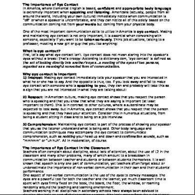
Eye 422e31
December 2021 0
Ds-1 Volumen 3 Adenda 7.pdf 284j
November 2022 0
Temasselectosdebiologia Vazquez Patria 4v2p6v
April 2020 105
Fisica1 Perez Patria 2e2s5w
June 2020 5
Confiabilidad De Los Inventarios.pdf 4y2ib
December 2019 20