Ecodrive 03 - Instruction Manual c6l1w
This document was ed by and they confirmed that they have the permission to share it. If you are author or own the copyright of this book, please report to us by using this report form. Report 3b7i
Overview 3e4r5l
& View Ecodrive 03 - Instruction Manual as PDF for free.
More details w3441
- Words: 9,369
- Pages: 44
Courtesy of CMA/Flodyne/Hydradyne ▪ Motion Control ▪ Hydraulic ▪ Pneumatic ▪ Electrical ▪ Mechanical ▪ (800) 426-5480 ▪ www.cmafh.com
Electric Drives and Controls
Hydraulics
Linear Motion and Assembly Technologies
Rexroth EcoDrive 03 Drive Controllers DKC**.3-040, -100, -200 Instruction Manual
Pneumatics
Service
R911320342 Edition 01
Courtesy of CMA/Flodyne/Hydradyne ▪ Motion Control ▪ Hydraulic ▪ Pneumatic ▪ Electrical ▪ Mechanical ▪ (800) 426-5480 ▪ www.cmafh.com
About this Documentation
Title
Rexroth EcoDrive 03
Rexroth EcoDrive 03 Drive Controllers DKC03.3-040, -100, -200
Type of Documentation Document Typecode Internal File Reference Purpose of Documentation
Record of Revisions
Copyright
Instruction Manual DOK-ECODR3-DKC40*200UL-IB01-EN-P 120-1000-B364-01/EN This documentation provides information on the installation and operation of the described products, by persons trained and qualified to work with electrical installations.
Description
Release Date
Notes
Instruction Manual
03.2007
1st edition
2007 Bosch Rexroth AG Copying this document, giving it to others and the use or communication of the contents thereof without express authority, are forbidden. Offenders are liable for the payment of damages. All rights are reserved in the event of the grant of a patent or the registration of a utility model or design (DIN 34-1).
Validity
Published by
The specified data is for product description purposes only and may not be deemed to be guaranteed unless expressly confirmed in the contract. All rights are reserved with respect to the content of this documentation and the availability of the product. Bosch Rexroth AG Bgm.-Dr.-Nebel-Str. 2 • D-97816 Lohr a. Main Telephone +49 (0)93 52/40-0 • Tx 68 94 21 • Fax +49 (0)93 52/40-48 85 http://www.boschrexroth.com/ BRC/EDY4..(NN).
DOK-ECODR3-DKC40*200UL-IB01-EN-P
Courtesy of CMA/Flodyne/Hydradyne ▪ Motion Control ▪ Hydraulic ▪ Pneumatic ▪ Electrical ▪ Mechanical ▪ (800) 426-5480 ▪ www.cmafh.com
Rexroth EcoDrive 03 DKC**.3-040...200
Contents I
Contents 1
Important Notes 1.1
1-1
Safety Instructions ........................................................................................................................ 1-1 General Information................................................................................................................. 1-1 with Electrical Parts.................................................................................................... 1-2 Handling and Assembly........................................................................................................... 1-2 Dangerous Movements ........................................................................................................... 1-2 Magnetic and Electromagnetic Fields ..................................................................................... 1-4 Hot Parts.................................................................................................................................. 1-4
1.2
2
Appropriate Use............................................................................................................................ 1-4
Identification
2-1
2.1
Type Code .................................................................................................................................... 2-1
2.2
Type Plates ................................................................................................................................... 2-1
2.3
Scope of Supply............................................................................................................................ 2-2
3
Ratings and Dimensions
3-1
4
Reference Documentations
4-1
4.1
5
Overview ....................................................................................................................................... 4-1
Instructions for Use
5-1
5.1
Overcurrent Protection.................................................................................................................. 5-1
5.2
Connections .................................................................................................................................. 5-1 Wiring Diagram ........................................................................................................................ 5-1 Connection Diagram ................................................................................................................ 5-2 X1, Connections for Control voltage........................................................................................ 5-3 Connection of Control Interfaces and Terminals ..................................................................... 5-6 X5, DC bus, Motor and Mains Connections ............................................................................ 5-6 X6, Motor temperature monitoring and holding brakes ........................................................... 5-9 X7, Connection for Programming module ............................................................................. 5-14 X12, Optional Choke Connection for DKC**.3-200-7 ............................................................ 5-15 XE1, XE2 Protective conductor connections for motor and mains........................................ 5-16 XS1, XS2, XS3 Shield Connections ...................................................................................... 5-17
5.2
Installation................................................................................................................................... 5-17 General Information on How to Install the Drive Controller ................................................... 5-17 Touch Guard at Devices........................................................................................................ 5-19 Sizing of Enclosure and Control Cabinet............................................................................... 5-20
DOK-ECODR3-DKC40*200UL-IB01-EN-P
Courtesy of CMA/Flodyne/Hydradyne ▪ Motion Control ▪ Hydraulic ▪ Pneumatic ▪ Electrical ▪ Mechanical ▪ (800) 426-5480 ▪ www.cmafh.com
II Contents 6
7
Appendix
Rexroth EcoDrive 03 DKC**.3-040...200
6-1
6.1
Discharging of DC Bus Capacitors ............................................................................................... 6-1
6.2
Discharging Device....................................................................................................................... 6-2
Index
7-1
DOK-ECODR3-DKC40*200UL-IB01-EN-P
Courtesy of CMA/Flodyne/Hydradyne ▪ Motion Control ▪ Hydraulic ▪ Pneumatic ▪ Electrical ▪ Mechanical ▪ (800) 426-5480 ▪ www.cmafh.com
Rexroth EcoDrive 03 DKC**.3-040...200
1
Important Notes
1.1
Safety Instructions
Important Notes 1-1
General Information • Do not attempt to install or commission this device without first reading all documentations provided with the product. Read and understand these safety instructions and all documentation prior to working with the device. If you do not have the documentation for the device, your responsible Bosch Rexroth sales representative. Ask for these documents to be sent immediately to the person or persons responsible for the safe operation of the device. • If these documentations contain some information you do not understand, it is absolutely necessary that you ask Bosch Rexroth for explanation before you start working on or with the devices. • Only persons who are trained and qualified for the use and operation of the device may work on this device or within its proximity. The persons are qualified if they have sufficient knowledge of the assembly, installation and operation of the equipment as well as an understanding of all warnings and precautionary measures noted in this documentation. • Only trained, instructed and qualified persons are allowed to switch electrical circuits and devices on and off in accordance with technical safety regulations, to ground them and to mark them according to the requirements of safe work practices. These persons must have adequate safety equipment and be trained in first aid. • Technical data, connections and operational conditions are specified in the reference documentations for the product and must be followed at all times. • If the products take the form of hardware, then they must remain in their original state, in other words, no structural changes are permitted. It is not permitted to decompile software products or alter source codes. • Do not mount damaged or faulty products or use them in operation. • Only use spare parts and accessories approved by Bosch Rexroth. • Follow all safety regulations and requirements for the specific application as practiced in the country of use. • If the device is resold, rented and/or ed on to others in any other form, these safety instructions must be delivered with the device in the official language of the 's country. • Proper and correct transport, storage, assembly and installation as well as care in operation and maintenance are prerequisites for optimal and safe operation of this device. Observe the data contained in the corresponding product documentations.
WARNING
Improper use of these devices, failure to follow the safety instructions in this document or tampering with the product, including disabling of safety devices, may result in material damage, bodily harm, electric shock or even death! Observe the following safety instructions!
⇒
DOK-ECODR3-DKC40*200UL-IB01-EN-P
Courtesy of CMA/Flodyne/Hydradyne ▪ Motion Control ▪ Hydraulic ▪ Pneumatic ▪ Electrical ▪ Mechanical ▪ (800) 426-5480 ▪ www.cmafh.com
1-2 Important Notes
Rexroth EcoDrive 03 DKC**.3-040...200
with Electrical Parts High electrical voltage! Danger to life, electric shock and severe bodily injury! • Follow general construction and safety regulations when working on power installations. DANGER
• Before switching on the device, the equipment grounding conductor must have been non-detachably connected to all electrical equipment and motors in accordance with the connection diagram. The equipment grounding conductor of the electrical equipment and the units must be non-detachably and permanently connected to the power supply unit at all times. The leakage current is greater than 3.5 mA. 2
Over the total length, use copper wire of a cross section of a minimum of 10 mm for this equipment grounding connection! • Before working with electrical parts with voltage potentials higher than 50 V, the device must be disconnected from the mains voltage or power supply unit. Provide a safeguard to prevent reconnection. • Wait 30 minutes after switching off power to allow capacitors to discharge before beginning to work. Measure the electric voltage on the capacitors before beginning to work to make sure that the equipment is safe to touch. • Never touch the electrical connection points of a component while power is turned on. • Install the covers and guards provided with the equipment properly before switching the device on. Before switching the equipment on, cover and safeguard live parts safely to prevent with those parts. • A residual-current-operated circuit-breaker or r.c.d. cannot be used for electric drives! Indirect must be prevented by other means, for example, by an overcurrent protective device according to the relevant standards.
Handling and Assembly Risk of injury by improper handling! Bodily injury by bruising, shearing, cutting, hitting! • Observe the general construction and safety regulations on handling and assembly. • Use suitable devices for assembly and transport. CAUTION
• Avoid jamming and bruising by appropriate measures. • Always use suitable tools. Use special tools if specified. • Use lifting equipment and tools in the correct manner. • If necessary, use suitable protective equipment (for example safety goggles, safety shoes, safety gloves). • Do not stand under hanging loads. • Immediately clean up any spilled liquids because of the danger of skidding.
Dangerous Movements Dangerous movements can be caused by faulty control of connected motors. Some common examples are: • improper or wrong wiring of cable connections • incorrect operation of the equipment components • wrong input of parameters before commissioning • malfunction of sensors, encoders and monitoring devices • defective components • software or firmware errors
DOK-ECODR3-DKC40*200UL-IB01-EN-P
Courtesy of CMA/Flodyne/Hydradyne ▪ Motion Control ▪ Hydraulic ▪ Pneumatic ▪ Electrical ▪ Mechanical ▪ (800) 426-5480 ▪ www.cmafh.com
Rexroth EcoDrive 03 DKC**.3-040...200
Important Notes 1-3
Dangerous movements can occur immediately after equipment is switched on or even after an unspecified time of trouble-free operation. The monitoring in the drive components will normally be sufficient to avoid faulty operation in the connected drives. Regarding personal safety, especially the danger of bodily harm and material damage, this alone cannot be relied upon to ensure complete safety. Until the integrated monitoring functions become effective, it must be assumed in any case that faulty drive movements will occur. The extent of faulty drive movements depends upon the type of control and the state of operation.
DANGER
Dangerous movements! Danger to life, risk of injury, severe bodily harm or material damage! • For the above reasons, ensure personal safety by means of qualified and tested higherlevel monitoring devices or measures integrated in the installation. They have to be provided for by the according to the specific conditions within the installation and a hazard and fault analysis. The safety regulations applicable for the installation have to be taken into consideration. Unintended machine motion or other malfunction is possible if safety devices are disabled, byed or not activated. To avoid accidents, bodily harm and/or material damage: • Keep free and clear of the machine’s range of motion and moving parts. Possible measures to prevent people from accidentally entering the machine’s range of motion: –
use safety fences
–
use safety guards
–
use protective coverings
–
install light curtains or light barriers
• Fences and coverings must be strong enough to resist maximum possible momentum. • Mount the emergency stop switch in the immediate reach of the operator. that the emergency stop works before startup. Don’t operate the device if the emergency stop is not working. • Isolate the drive power connection by means of an emergency stop circuit or use a safety related starting lockout to prevent unintentional start. • Make sure that the drives are brought to a safe standstill before accessing or entering the danger zone. • Additionally secure vertical axes against falling or dropping after switching off the motor power by, for example: –
mechanically securing the vertical axes,
–
adding an external braking/ arrester/ clamping mechanism or
–
ensuring sufficient equilibration of the vertical axes.
• The standard equipment motor brake or an external brake controlled directly by the drive controller are not sufficient to guarantee personal safety! • Disconnect electrical power to the equipment using a master switch and secure the switch against reconnection for: –
maintenance and repair work
–
cleaning of equipment
–
long periods of discontinued equipment use
• Prevent the operation of high-frequency, remote control and radio equipment near electronics circuits and supply leads. If the use of such devices cannot be avoided, the system and the installation for possible malfunctions in all possible positions of normal use before initial startup. If necessary, perform a special electromagnetic compatibility (EMC) test on the installation.
DOK-ECODR3-DKC40*200UL-IB01-EN-P
Courtesy of CMA/Flodyne/Hydradyne ▪ Motion Control ▪ Hydraulic ▪ Pneumatic ▪ Electrical ▪ Mechanical ▪ (800) 426-5480 ▪ www.cmafh.com
1-4 Important Notes
Rexroth EcoDrive 03 DKC**.3-040...200
Magnetic and Electromagnetic Fields
WARNING
Health hazard for persons with heart pacemakers, metal implants and hearing aids in proximity to electrical equipment! • Persons with heart pacemakers and metal implants are not permitted to enter following areas: –
Areas in which electrical equipment and parts are mounted, being operated or commissioned.
–
Areas in which parts of motors with permanent magnets are being stored, repaired or mounted.
• If it is necessary for somebody with a pacemaker to enter such an area, a doctor must be consulted prior to doing so. The interference immunity of present or future implanted heart pacemakers differs greatly, so that no general rules can be given. • Those with metal implants or metal pieces, as well as with hearing aids must consult a doctor before they enter the areas described above. Otherwise health hazards may occur.
Hot Parts Hot surfaces at motor housings, on drive controllers or chokes! Danger of burns! • Do not touch surfaces of device housings and chokes in the proximity of heat sources! Danger of burns! CAUTION
• Do not touch housing surfaces of motors! Danger of burns! • According to operating conditions, temperatures can be higher than 60 °C (140 °F) during or after operation. • Before accessing motors after having switched them off, let them cool down for a sufficiently long time. Cooling down can require up to 140 minutes! Roughly estimated, the time required for cooling down is five times the thermal time constant specified in the Technical Data. • Wear safety gloves or do not work at hot surfaces. • For certain applications, the manufacturer of the end product, machine or installation, according to the respective safety regulations, has to take measures to avoid injuries caused by burns in the end application. These measures can be, for example: warnings, guards (shielding or barrier), technical documentation.
1.2
Appropriate Use This product may only be used for the applications mentioned in the reference documentations (see chapter “Reference Documentations”) and under the described application, ambient and operating conditions.
DOK-ECODR3-DKC40*200UL-IB01-EN-P
Identification 2-1
Courtesy of CMA/Flodyne/Hydradyne ▪ Motion Control ▪ Hydraulic ▪ Pneumatic ▪ Electrical ▪ Mechanical ▪ (800) 426-5480 ▪ www.cmafh.com
Rexroth EcoDrive 03 DKC**.3-040...200
2
Identification
2.1
Type Code Note:
The following figure illustrates the basic structure of the type code. Our sales representative will help you with the current status of available versions.
Example:
Type code fields:
DKC
Drive controller
xx
Series
3
Version Type current 16 A 40 A 100 A 200 A
016 040 100 200
Voltage category
7 FW
Firmware A firmware specifying the functions of the drive must be ordered separately.
Fig. 2-1:
2.2
DKC 03.3 - 040 - 7 - FW
TL0001F1.FH7
Type code
Type Plates Basic Unit Barcode
Serial number
Hardware index TS0012F1.FH7
Fig. 2-2:
Type plate
Unit type Part number
Device type Production week
Serial number
Hardware index
Barcode TS0014F1.FH7
Fig. 2-3:
DOK-ECODR3-DKC40*200UL-IB01-EN-P
Type plate – DKC example
Courtesy of CMA/Flodyne/Hydradyne ▪ Motion Control ▪ Hydraulic ▪ Pneumatic ▪ Electrical ▪ Mechanical ▪ (800) 426-5480 ▪ www.cmafh.com
2-2 Identification
2.3
Rexroth EcoDrive 03 DKC**.3-040...200
Scope of Supply • firmware module • protection • connectors according to the following table:
Type
Connectors - type independent X.. 1
2
Connectors - type dependent X..
3
4
6
8
9
10
11
15
DKC01.3-***-7
X
X
X
X
X
X
X
X
X
DKC02.3-***-7
X
X
X
X
X
X
X
X
DKC03.3-***-7
X
X
X
X
X
X
X
X
DKC04.3-***-7
X
X
X
X
X
X
X
X
DKC05.3-***-7
X
X
X
X
X
X
X
X
DKC06.3-***-7
X
X
X
X
X
X
X
X
DKC11.3-***-7
X
X
X
X
X
X
X
X
DKC21.3-***-7
X
X
X
X
X
X
X
X
DKC22.3-***-7
X
X
X
X
X
X
X
X
20
21
30
40
41
50
60
210
X
Fig. 2-4: Connectors for DKC**.3-040...200-7-FW included in the scope of supply
DOK-ECODR3-DKC40*200UL-IB01-EN-P
Ratings and Dimensions 3-1
Courtesy of CMA/Flodyne/Hydradyne ▪ Motion Control ▪ Hydraulic ▪ Pneumatic ▪ Electrical ▪ Mechanical ▪ (800) 426-5480 ▪ www.cmafh.com
Rexroth EcoDrive 03 DKC**.3-040...200
3
Ratings and Dimensions
Description
Symbol
Unit
DKC03.3-040
listing according UL-standard (UL)
DKC03.3-100
DKC03.3-200
UL 508 C
listing according CSA-standard (UL)
Canadian National Standard(s) C22.2 No. 14-05
UL files (UL)
E134201
pollution degree (UL)
E134201
E134201
Use in a pollution degree 2 environment
maximum ambient temperature with nominal data (UL)
Tamax
°C
45
45
45
maximum ambient temperature with reduced nominal data (UL)
Tamax_red
°C
55
55
55
m
kg
5,7
9,7
19,5
H
mm
360
360
360
T
mm
261
261
261
B
mm
65
105
230
dtop
mm
150
150
150
dbot
mm
80
80
80
UN3
V
24
24
24
PN3
W
21
26
29
ISCCR
A rms
42000
42000
42000
V
200 … 480
200 … 480
200 … 480
%
±10
±10
±10
1 × AC, 3 × AC
1 × AC, 3 × AC
1 × AC, 3 × AC
Hz
50 … 60
50 … 60
50 … 60
Hz
2
2
2
A
16
40
38
20
70
70
Weight Device height (UL)
1)
Device depth (UL)
2)
Device width (UL)
3)
minimum distance on the top of the device
4)
minimum distance on the bottom of the device 5)
rated control voltage input (UL)
6)
rated power consumption control voltage input without holding brake, without control section 7) at UN3 = DC 24 V (UL) short circuit current rating, SCCR, 8) symmetrical amperes (UL) rated input voltage, power (UL)
9)
tolerance rated input voltage (UL) input number of phases (UL) input frequency (UL)
fLN
tolerance input frequency (UL) maximum input current (UL)
10)
branch circuit protection fuse (UL) field wiring material (UL)
IL_cont 11)
Use 60/75 °C copper wire only, use class 1 wire only or equivalent
12)
required wire size according UL 508 A 13) (internal wiring); at IL_cont (UL)
ALN
maximum output voltage (UL)
Uout
V
output number of phases (UL) maximum output current (UL) maximum output frequency (UL)
DOK-ECODR3-DKC40*200UL-IB01-EN-P
AWG 12
AWG 8
AWG
800
800
800
3
3
3
Iout_max
A
40
100
200
fout
Hz
1000
1000
1000
Courtesy of CMA/Flodyne/Hydradyne ▪ Motion Control ▪ Hydraulic ▪ Pneumatic ▪ Electrical ▪ Mechanical ▪ (800) 426-5480 ▪ www.cmafh.com
3-2 Ratings and Dimensions
Rexroth EcoDrive 03 DKC**.3-040...200
Description
Symbol
power dissipation at continuous current Iout_cont and continuous DC bus power PDC_cont PDiss_cont 14) respectively (UL) 1) 2) 3)
Unit
DKC03.3-040
DKC03.3-100
DKC03.3-200
W
180
420
960
Abb. 3-1:
housing dimension; see related dimension sheet also see fig. "Air inlet and outlet of drive controller" observe supply voltage for motor holding brakes find value for control section in project planning manual Suitable for use on a circuit capable of delivering not more than this SCCR value, 600 V AC or less. The drive series shall be used with listed AC input line fuses or listed circuit breakers specified in this documentation. DKC, CZM, BZM: DC bus L+, L-; Mains input L1, L2, L3 at PDC_cont class J branch circuit fuse find value for tightening torque in project planning manual, electrical terminals copper wire; PVC-insulation (conductor temperature 90 °C); Table 13.5.1; Ta ≤ 40 °C plus dissipation of braking resistor UL ratings and dimensions
A: B: C: dtop: dbot: Fig. 3-2:
air intake air outlet mounting surface in control cabinet distance top distance bottom Air intake and air outlet at drive controller
4) 5) 6) 7) 8)
9) 10) 11) 12) 13) 14)
Distances
DOK-ECODR3-DKC40*200UL-IB01-EN-P
Reference Documentations 4-1
Courtesy of CMA/Flodyne/Hydradyne ▪ Motion Control ▪ Hydraulic ▪ Pneumatic ▪ Electrical ▪ Mechanical ▪ (800) 426-5480 ▪ www.cmafh.com
Rexroth EcoDrive 03 DKC**.3-040...200
4
Reference Documentations
4.1
Overview
Title
Type
Document Typecode
Servo Applications with 1,5 s Acceleration Time
Selection lists
DOK-ECODR3-SERV-GEN***-AUxx-MS-P
Servo Applications with 400 ms Acceleration Time
Selection lists
DOK-ECODR3-SERV-WZM***-AUxx-MS-P
Main drives with 2AD-, ADF and 1MB-motors
Selection lists
DOK-ECODR3-MAIN*WZM***-AUxx-MS-P
List of Connecting Cables for DIAX04 and ECODRIVE03
Selection lists
DOK-CONNEC-CABLE*STAND-AUxx-EN-P
ECODRIVE03 Drive for Machine Tool Applications With SERCOS-, Analog and Parallel interface
Functional Description
DOK-ECODR3-SMT-01VRS**-FKxx-EN-P
ECODRIVE03 Drive for Machine Tool Applications With SERCOS-, Analog and Parallel interface
Functional Description
DOK-ECODR3-SMT-02VRS**-FKxx-EN-P
ECODRIVE03 Drive for General Automation With SERCOS-, Analog and Parallel interface
Functional Description
DOK-ECODR3-SGP-01VRS**-FKxx-EN-P
ECODRIVE03 Drive for General Automation With Fieldbus-Interfaces
Functional Description
DOK-ECODR3-FGP-01VRS**-FKxx-EN-P
ECODRIVE03 Drive for General Automation With Fieldbus-Interfaces
Functional Description
DOK-ECODR3-FGP-02VRS**-FKxx-EN-P
ECODRIVE03 Drive for General Automation With Fieldbus-Interfaces
Functional Description
DOK-ECODR3-FGP-03VRS**-FKxx-EN-P
Application Manual
DOK-CONNEC-CABLE*LWL-AWxx-EN-P
LWL Handling Electromagnetic Compatibility (EMC) in Drive and Control Systems
Project Planning Manual DOK-GENERL-EMV********-PRxx-EN-P
Digital AC Motors MKD
Project Planning Manual DOK-MOTOR*-MKD********-PRxx-EN-P
Digital AC Motors MHD
Project Planning Manual DOK-MOTOR*-MHD********-PRxx-EN-P
MKE Digital AC Motors for potentially explosive areas
Project Planning Manual DOK-MOTOR*-MKE********-PRxx-EN-P
2AD AC Motor
Project Planning Manual DOK-MOTOR*-2AD********-PRxx-EN-P
ADF Main Spindle Motors
Project Planning Manual DOK-MOTOR*-ADF********-PRxx-EN-P
1MB Frameless Spindle Motor
Project Planning Manual DOK-MOTOR*-1MB********-PRxx-EN-P
Synchronous MBS Kit Spindle Motors
Project Planning Manual DOK-MOTOR*-MBS********-PRxx-EN-P
LAR 070-132 Gehäuse-Linearmotoren
Selection and Project Planning
DOK-MOTOR*-LAR********-AWxx-DE-P
LAF050 – 121 Linear Motors
Selection and Project Planning
DOK-MOTOR*-LAF********-AWxx-EN-P
Linear Synchronous Direct Drives LSF
Project Planning Manual DOK-MOTOR*-LSF********-PRxx-EN-P
AC Drive Units in Personnel Conveyor Systems
Application Manual
DOK-GENERL-ANTR*PERSON-ANxx-EN-P
AC Drive Units in Hazardous Areas (Expl. Protection)
Application Manual
DOK-GENERL-ANTR*EXPLOS-ANxx-EN-P
ECODRIVE03 Drive for Machine Tool Applications With SERCOS-, Analog and Parallel interface
Troubleshooting Guide
DOK-ECODR3-SMT-01VRS**-WAR*-EN-P
DOK-ECODR3-DKC40*200UL-IB01-EN-P
Courtesy of CMA/Flodyne/Hydradyne ▪ Motion Control ▪ Hydraulic ▪ Pneumatic ▪ Electrical ▪ Mechanical ▪ (800) 426-5480 ▪ www.cmafh.com
4-2 Reference Documentations
Rexroth EcoDrive 03 DKC**.3-040...200
Title
Type
Document Typecode
ECODRIVE03 Drive for Machine Tool Applications With SERCOS-, Analog and Parallelinterface
Troubleshooting Guide
DOK-ECODR3-SMT-02VRS**-WAR*-EN-P
ECODRIVE03 Drive for General Automation With SERCOS-, Analog and Parallel interface
Troubleshooting Guide
DOK-ECODR3-SGP-01VRS**-WAxx-EN-P
ECODRIVE03 Drive for General Automation With Fieldbus-Interfaces
Troubleshooting Guide
DOK-ECODR3-FGP-01VRS**-WAxx-EN-P
ECODRIVE03 Drive for General Automation With Fieldbus-Interfaces
Troubleshooting Guide
DOK-ECODR3-FGP-02VRS**-WAxx-EN-P
ECODRIVE03 Drive for General Automation With Fieldbus-Interfaces
Troubleshooting Guide
DOK-ECODR3-FGP-03VRS**-WAxx-EN-P
1)
Fig. 4-1:
In the document typecodes, "xx" is a wild card for the current edition of the documentation (example: "PR01" is the first edition of a Project Planning Manual) Documentations - Overview
DOK-ECODR3-DKC40*200UL-IB01-EN-P
Instructions for Use 5-1
Courtesy of CMA/Flodyne/Hydradyne ▪ Motion Control ▪ Hydraulic ▪ Pneumatic ▪ Electrical ▪ Mechanical ▪ (800) 426-5480 ▪ www.cmafh.com
Rexroth EcoDrive 03 DKC**.3-040...200
5
Instructions for Use
5.1
Overcurrent Protection Branch circuit protection has to be provided externally according to the maximum values (voltage and current or voltage and percent of FLA of the fuses [FLA: Full Load Ampacity]).
5.2
Connections
Wiring Diagram mains voltage DST
transformer
NFD
line filter for power connections fuse
line filter for power supply unit
Q1
NFE line or
power supply unit K1
NTM
drive controller DC 24 V firmware
DKC
BZM
auxiliary bleeder module
CZM auxiliary capacitance module
FWA
IKS - ready-made cable IKG - ready-made power cable AC motor components shown in gray are absolutely necessary. Fa5035f1.fh7
Fig. 5-1:
DOK-ECODR3-DKC40*200UL-IB01-EN-P
Overview of individual components
Courtesy of CMA/Flodyne/Hydradyne ▪ Motion Control ▪ Hydraulic ▪ Pneumatic ▪ Electrical ▪ Mechanical ▪ (800) 426-5480 ▪ www.cmafh.com
5-2 Instructions for Use
Rexroth EcoDrive 03 DKC**.3-040...200
Connection Diagram Rexroth EcoDrive 03 (DKC**.040, DKC**.100, DKC**.200)
Fig. 5-2:
Total connection diagram for DKC**.3
DOK-ECODR3-DKC40*200UL-IB01-EN-P
Instructions for Use 5-3
X1, Connections for Control voltage Technical description of connector 5 6 7 8
1 2 3 4
Illustration:
Ap5264f1.FH7
Fig. 5-3: Design:
Connector X1
Type
No. of pins
Design
2x4
Bushing on connector
Cross section multi core wire [mm²]
Wire size in AWG Gauge no.:
Spring Fig. 5-4: Design Connection cross section:
Cross section single wire [mm²] Fig. 5-5:
0,2-2,5 1,5-2,5 Connection cross section
16-12
24V control voltage supply (+24V and 0V) Connection +24V and 0V:
device-external
connection for control voltage
connection for control voltage to additional DKCs
X1 1 2 3 4
device-internal
+24V 0V
5 6 7 8
+24V 0V
AP5121F1.FH7
Fig. 5-6:
Connections for control voltage X1
X1 5 6 7 8
1 2 3 4
5 6 7 8
24V
1 2 3 4
Courtesy of CMA/Flodyne/Hydradyne ▪ Motion Control ▪ Hydraulic ▪ Pneumatic ▪ Electrical ▪ Mechanical ▪ (800) 426-5480 ▪ www.cmafh.com
Rexroth EcoDrive 03 DKC**.3-040...200
to additional devices
Ap5139f1.fh7
Fig. 5-7: Connection loads +24V and 0V:
Looping through control voltage
Voltage at X1/1 against X1/2: Current or power consumption X1/1: Reverse voltage protection: Max. allowed current load when looping through the control voltage via X1.1/2 to X1.5/6:
Note:
DOK-ECODR3-DKC40*200UL-IB01-EN-P
See chapter "Ratings and Dimensions" Via allowed voltage range using internal protection diodes DC 10 A
Strong mechanical influence on the test tap of the terminals can increase the transition resistance and destroy the terminals.
Courtesy of CMA/Flodyne/Hydradyne ▪ Motion Control ▪ Hydraulic ▪ Pneumatic ▪ Electrical ▪ Mechanical ▪ (800) 426-5480 ▪ www.cmafh.com
5-4 Instructions for Use
Rexroth EcoDrive 03 DKC**.3-040...200
Note:
wire +24V and 0V:
The input 0 V is connected directly to the device potential. The utilization of an insulation monitoring for +24 V and 0 V against device is therefore not possible!
wire cross section:
min. 1 mm² for looping through: min. 2,5 mm²
wire routing:
parallel if possible
Max. allowed inductance between 24V source and X1:
Note:
100 µH (equals about 2 x 75 m)
If the cross sections of the lines for looping through the control voltage are too small, the terminals can be damaged.
Note: • Exceeding allowed control voltage generates error message "+24 volt error". (=> See also firmware functional description.) • Control voltage failure causes the running motor to coast torque-free (without brake).
Dangerous movements due to unbraked coasting of motor with control voltage failure!
⇒ DANGER
⇒
Personnel should not remain within the area of the machine with moving parts. Possible preventive steps against unauthorized access are: – protective fencing – bars – covers – light barriers The fences must be able to withstand the maximum possible force that the machine can generate.
Drive halt (AH) and Drive enable (RF) Note: • Inputs work with inactive bus communication. • Inputs don't work with active bus communication (SERCOS interface, Profibus-DP, ...). Connection AH and RF:
device-external
device-internal
X1
drive halt drive enable
1 2 3 4
AH RF
5 6 7 8
AP5270F1.FH7
Fig. 5-8:
Connections for drive halt and drive enable
DOK-ECODR3-DKC40*200UL-IB01-EN-P
Instructions for Use 5-5
Courtesy of CMA/Flodyne/Hydradyne ▪ Motion Control ▪ Hydraulic ▪ Pneumatic ▪ Electrical ▪ Mechanical ▪ (800) 426-5480 ▪ www.cmafh.com
Rexroth EcoDrive 03 DKC**.3-040...200
Input circuit AH and RF:
R1
R3
I
n
R2
C1
Ap5183f1.fh7
Schematics R1: R2: R3: C1: Fig. 5-9: Inputs AH and RF:
10k 3k3 10k no data Input circuit
Input voltage:
min.
max.
High
16 V
30 V
Low
-0.5 V
3V
Input resistance
13.3 kOhm ±5%
Reaction time Fig. 5-10: Inputs
See firmware functional description
AH:
The drive halt function is used to bring an axis to standstill with defined acceleration and jerk (see firmware functional description).
RF:
The input drive enable (RF) activates the drive with a 0-1 edge. Note:
If the inputs are controlled by a power supply other than the DC24 volt supply of the drive controller, then the reference lead of the other power supply must be connected to X1.2 (0 V).
Ready to operate Bb Connection Bb:
device-external
device-internal
X1 1 2 3 4
ready for operation
5 6 7 8
Bb Bb
AP5122F1.FH7
Fig. 5-11: Loadability of the connection Bb:
Connections for ready to operate
max. switching voltage:
DC 40 V
max. switching current:
DC 1 A
max. continuous current:
DC 1 A
minimum load: Guaranteed number of switching operations at max. time constant of load < 50 ms:
DOK-ECODR3-DKC40*200UL-IB01-EN-P
10 mA 250,000
Courtesy of CMA/Flodyne/Hydradyne ▪ Motion Control ▪ Hydraulic ▪ Pneumatic ▪ Electrical ▪ Mechanical ▪ (800) 426-5480 ▪ www.cmafh.com
5-6 Instructions for Use Switching states Bb:
Rexroth EcoDrive 03 DKC**.3-040...200
The Bb s opens: • if control voltage for DKC is not applied • if 24 volts not present at the emergency stop input when the E-stop function is activated (depends on parameterization, see function description). • With an error in the drive (depends on parameterization, see firmware functional description: "Power off on error").
Damage possible if Bb not connected! The ready to operate Bb acknowledges the drive is ready for mains voltage. WARNING
⇒ ⇒
Integrate Bb as per "Control Circuits for the Mains Connection" (see project planning manual). The evaluation of the Bb by a PLC may not cause any operating delay of more than 10 ms.
Connection of Control Interfaces and Terminals See project planning manual for more details.
X5, DC bus, Motor and Mains Connections Lethal electric shock caused by live parts with more than 50 V! DANGER
⇒ ⇒ ⇒ ⇒
Before working on the drive controller, switch off the power supply via the main switch or the fuse. Always mount or dismount both connectors (motor connector and mains connector) on the drive controller at the same time. Connect the protective conductor connections XE1 and XE2 to the protective conductor system of the control cabinet. Check the continuity of the protective conductors from the mains connection to the connected motors. Observe information in chapter "Important Notes"
Technical description of connector Illustration:
L+ LL1
A1
L2
A2
L3
A3
Ap5267f1.FH7
Fig. 5-12:
Connector X5
DOK-ECODR3-DKC40*200UL-IB01-EN-P
Instructions for Use 5-7
Rexroth EcoDrive 03 DKC**.3-040...200
Courtesy of CMA/Flodyne/Hydradyne ▪ Motion Control ▪ Hydraulic ▪ Pneumatic ▪ Electrical ▪ Mechanical ▪ (800) 426-5480 ▪ www.cmafh.com
Design:
Type
No. of pins
Design
connection block
2/3/3
screw-in connection for ring terminals M5
Fig. 5-13: Tightening torque:
Design
min. tightening torque [Nm]
max. tightening torque [Nm]
2.5
3.0
Fig. 5-14: Tightening torque Connection cross section:
Cross section single wire [mm²] Fig. 5-15:
max. connectable cross section [mm²]
Wire Size in AWG gauge no.:
-25 Connection cross section
--
DC bus connection The DC bus connection connects several controllers to each other plus it connects controllers together with auxiliary components •
Increase allowed DC bus continuous power
•
Increase allowed bleeder continuous load
•
Allow connections for "Central supply"
Connection DC bus:
device-external
device-internal
X5 DC bus connection
L+ L-
AP5301F1.FH7
Fig. 5-16:
DC bus connection
Damage possible if DC bus connections L+ and L- are reversed!
⇒
Make sure polarity is correct.
CAUTION wire DC bus:
If the DC bus rails supplied do not make a connection possible, then use short twisted wires to do so. wire length: wire cross section:
wire protection Voltage resistance of individual wires to ground
DOK-ECODR3-DKC40*200UL-IB01-EN-P
max. 2 x 1 m min. 10 mm², not smaller than the cross section of the mains supply lead With a fuse in the mains connections > 750 V (e.g., litz wires - H07)
Courtesy of CMA/Flodyne/Hydradyne ▪ Motion Control ▪ Hydraulic ▪ Pneumatic ▪ Electrical ▪ Mechanical ▪ (800) 426-5480 ▪ www.cmafh.com
5-8 Instructions for Use
Rexroth EcoDrive 03 DKC**.3-040...200
Motor connection Connection Motor:
device-external
device-internal
X5
motor connection
A1 A2 A3
AP5302F1.FH7
Fig. 5-17: Cable Motor:
Motor connections
Use Rexroth motor power cables to connect motor and controller. Note:
For technical data on connections and cross sections, see the motor project planning manual.
Cable length: Maximum length equals 75 m: • With two connections between controller and motor (e.g., plugs at exit of control cabinet and at machine) • Standard cables from Rexroth • Ambient temperatures of ≤ 40 °C per EN 60 204 • Switch frequency of 4 kHz Maximum allowed capacitance per unit length at A1, A2, A3: • with regard to ground: 0.5 nF/m • cable to cable: 0.5 nF/m Maximum allowed inductance per unit length an A1, A2, A3: • 100 nH/m To maintain EMC values, the motor cable length is limited with a switching frequency of > 4 kHz. It is largely dependent on the application and ambient conditions at the installation and machine. A guide value is listed below: Cycle frequency drive controller
Max. length for class B, EN 55011
Max. length for class A, EN 55011
standard setting switching frequency 4 kHz
75 m
75 m
parameter setting switching 25 m frequency 8 kHz Fig. 5-18: Guide value for maximum motor cable lengths Protective conductor connection
50 m
XE1
WARNING
No guarantee! If third party cables are used, then the guarantee is forfeited for the entire system. Use Rexroth cables!
⇒
DOK-ECODR3-DKC40*200UL-IB01-EN-P
Instructions for Use 5-9
Mains connections The mains connector serves as the connection of the drive controller with the power supply. Single-phase mains connection:
device-external
device-internal
X5
L1 N
L1 L2 L3
n.c.
AP5370F1.FH7
Fig. 5-19:
Single-phase mains connection
Three-phase mains connection:
device-external
device-internal
X5
mains connection
L1 L2 L3
L1 L2 L3
AP5303F1.FH7
Fig. 5-20: Protective conductor connection
Three-phase mains connection
XE2 Note:
Mains connections should not be daisy-chained between the units (intermediate connectors for the supply source should be used).
Note:
If applicable, an additional input filter SUP-M03-DKCxxx.3 NFD must be installed.
X6, Motor temperature monitoring and holding brakes Technical description of connector 5 6 7 8
Illustration:
1 2 3 4
Courtesy of CMA/Flodyne/Hydradyne ▪ Motion Control ▪ Hydraulic ▪ Pneumatic ▪ Electrical ▪ Mechanical ▪ (800) 426-5480 ▪ www.cmafh.com
Rexroth EcoDrive 03 DKC**.3-040...200
Ap5264f1.FH7
Fig. 5-21: Design:
Connector X6
Type Spring Fig. 5-22: Design
DOK-ECODR3-DKC40*200UL-IB01-EN-P
No. of pins
Design
2x4
Bushing on connector
5-10 Instructions for Use
Rexroth EcoDrive 03 DKC**.3-040...200
Courtesy of CMA/Flodyne/Hydradyne ▪ Motion Control ▪ Hydraulic ▪ Pneumatic ▪ Electrical ▪ Mechanical ▪ (800) 426-5480 ▪ www.cmafh.com
Connection cross section:
Cross section single wire [mm²] Fig. 5-23:
Cross section multi core wire [mm²]
Cross section in AWG Gauge no.:
0.2-2.5 1,5-2,5 Connection cross section
16-12
Damages by exchanging the connectors X6.1-4 and X6.5-8! CAUTION
⇒ Do not exchange connectors X6.1-4 and X6.5-8. ⇒ Only use lines with sufficient cross section.
Motor temperature monitoring (TM+, TM) Connections TM+ and TM- are used to evaluate the temperature of connected Rexroth motors. These are equipped with a temperaturedependent resistor (either PTC or NTC dependent on the motor type) to monitor temperature. The connection leads are in the motor power cable. Connection monitoring TM+, TM-:
device-external
device-internal
X6 motor temperature monitoring
1 2
TM+ TM-
3 4 5 6 7 8
AP5297F1.FH7
Fig. 5-24: Motor temperature evaluation:
Motor temperature monitoring Drive Controller
G
U
MOTOR TM+
TMR
AP5326F1.FH7
Schematics U: approximately 5 V R: approximately 2 k Fig. 5-25: Motor temperature evaluation
Note:
⇒
Connections TM+ and TM- are only to be used with Rexroth motors.
See also firmware functional description : "Temperature monitoring".
DOK-ECODR3-DKC40*200UL-IB01-EN-P
Instructions for Use 5-11
Courtesy of CMA/Flodyne/Hydradyne ▪ Motion Control ▪ Hydraulic ▪ Pneumatic ▪ Electrical ▪ Mechanical ▪ (800) 426-5480 ▪ www.cmafh.com
Rexroth EcoDrive 03 DKC**.3-040...200
Holding brake (BR+, BR-) Dangerous movements! Danger to personnel from falling or dropping axes!
⇒
DANGER
⇒
The standard equipment motor brake or an external brake controlled directly by the servo drive are not sufficient to guarantee the safety of personnel! Personnel safety must be acquired with higherranking procedures: Dangerous areas should be blocked off with fences or grids. Secure vertical axes against falling or slipping after switching off the motor power by, for example: - Mechanically securing the vertical axes - Adding an external brake / clamping mechanism - Balancing and thus compensating for the vertical axes mass and the gravitational force
These connections control the holding brakes in the connected motors. For the switching performance, see function description. To connect external loads note allowed loads. Connection BR+, BR-:
device-external
device-internal
X6 1 2
holding brake voltage connection for brake voltage connection for brake to additional DKCs
3 4
BR+ BR-
5
UB 0VB UB 0VB
6 7 8
AP5298F1.FH7
Fig. 5-26:
Holding brake and voltage connection
Loadability of connections BR+, BR-: Units
DKC**.3-040-7, DKC**.3-100-7
max. switching voltage:
DKC**.3-200-7
DC 40 V
max. switching current:
DC 2 A
DC 4 A
max. continuous current:
DC 2 A
DC 4 A
Minimum load:
100 mA
Guaranteed number of switches at max. time constant of load <50ms (LBremse/(24V/IBremse)):
250.000
Short-circuit and overload protection in the row to the
present
DOK-ECODR3-DKC40*200UL-IB01-EN-P
Rexroth EcoDrive 03 DKC**.3-040...200
Voltage connection for brakes Note:
The motor holding brake is not supplied by the controller. Given one voltage source for brake and control voltage, use parallel leads from the voltage source. Insert the brake voltage supply cable in the touch guard from the bottom or from the side. Note the voltage range for the motor holding brake according to the motor projection.
Risk of damage!
⇒ CAUTION
The maximum allowed current load of the terminals for the voltage supply of the brake and the control voltage supply must also be observed in the case of a short circuit.
DKC
DKC
1 2 3 4
1 2 3 4
11121314 1516 1718 5 6 7 8
1 2 3 4
1 2 3 4 5 6 7 8 9
1 2 3 4
1 2 3 4 5 6 7 8 9
1 2 3 4 5 6 7 8 9
11121314 1516 1718 5 6 7 8
1 2 3 4 5 6 7 8 9
X1
X1
to additional devices
24V X6
X6 5 6 7 8
1 2 3 4
1 2 3 4
5 6 7 8
1 2 3 4
1 2 3 4
to the central ground
Ap5126f1.fh7
Fig. 5-27: Shared voltage source for brakes and control voltage supply
24V 5 6 7 8
1 2 3 4
5 6 7 8
1 2 3 4
Courtesy of CMA/Flodyne/Hydradyne ▪ Motion Control ▪ Hydraulic ▪ Pneumatic ▪ Electrical ▪ Mechanical ▪ (800) 426-5480 ▪ www.cmafh.com
5-12 Instructions for Use
to additional devices
X6
X6
Ap5140f1.fh7
Fig. 5-28:
Looping through the brake supply
DOK-ECODR3-DKC40*200UL-IB01-EN-P
Instructions for Use 5-13
Voltage connection for brakes on DKC:
Wire voltage connection for brake:
max. voltage at X6.5/7 against X6.6/8:
DC 40 V
current consumption at X6.5 and needed supply voltage:
see "Technical data" brake in the motor manual
max. allowed current load when looping through brake supply over X6.5/6 to X6.7/8:
DC 10 A
wire cross section:
min. 1 mm² for looping through: min. 2.5 mm²
Voltage resistance of single wire to ground
> 750 V (e.g.: litz wires - H07)
wire routing
parallel if possible (twisted)
max. inductance between 24 V source and X6
100 µH (equals about 2 x 75 m)
Risk of damage!
⇒ CAUTION
Risk of damage by increased transition resistance in the case of strong mechanical influence at the test tap.
Motor holding brake Controlling the motor holding brake: Technical data Motor holding brake:
The controller controls the holding brake. Supply voltage, current consumption, linking, separating time, holding torque, etc. see motor manual.
A1 A2
UB
0VB
0VB 8
7
6
UB
BR5
4
TM-
3
TM+ 1
X5
2
DKC
BR+
Basic connection of motor power, holding brake and motor temperature monitoring
X6
A3 XE1
XS1
0VExt
24V
G
F
H
E
D
C
B
24VExt
A
Courtesy of CMA/Flodyne/Hydradyne ▪ Motion Control ▪ Hydraulic ▪ Pneumatic ▪ Electrical ▪ Mechanical ▪ (800) 426-5480 ▪ www.cmafh.com
Rexroth EcoDrive 03 DKC**.3-040...200
U
M
AC-Motor
3 Temperature dependent resistance
Holding brake
AP5107F1.FH7
Fig. 5-29:
DOK-ECODR3-DKC40*200UL-IB01-EN-P
Connection of motor cable, holding brake and temperature monitor for motors with connectors
A1 A2
0VB
UB 7
8
6
UB
0VB
BR5
4
TM-
3
TM+ 1
X5
2
DKC
BR+
Rexroth EcoDrive 03 DKC**.3-040...200
X6
A3 XE1
XS1
0VExt
24V
BR-
X2
BR+
X1
T2
T1
W1
V1
U1
24VExt
AC-Motor
U
M 3
Holding brake
Temperature dependent resistance
AP5125F1.FH7
Fig. 5-30:
Connection of motor cable, holding brake and temperature monitor for motors with connector box
Note:
The cable designations and all details on making cables are outlined in the cable or motor document.
X7, Connection for Programming module Programming module The programming module can be broken down into • Parameter module for -specific parameters • Firmware modules for unit-specific firmware Programming module
S3 S2 S2 S3 1
9
1
8
1
8
SDS
3
6
3
7
3
7
3
6
8
0
2
7
2
7
90
2
8
1
5
0
4 5
9 0
4
9
ESF2
ISSI
S1 S1
Barcode Barcode
H1 H1
splSI2032 110LT48 H813A08
Firmware module IS61C6416-20T C2110900 9728
Parameter module
2
4
4 5
6
5
6
Courtesy of CMA/Flodyne/Hydradyne ▪ Motion Control ▪ Hydraulic ▪ Pneumatic ▪ Electrical ▪ Mechanical ▪ (800) 426-5480 ▪ www.cmafh.com
5-14 Instructions for Use
Ap5146f1.fh7
Fig. 5-31:
X7, Programming module
H1:
Diagnostic display
S1:
Reset key
S2, S3:
Address switch
DOK-ECODR3-DKC40*200UL-IB01-EN-P
Instructions for Use 5-15
Setting the Drive Address Switch S2, S3; drive address:
Two decade switches are used to set the drive address. It can be set to any number between 1 and 99. Example: Switch setting S3 = 9 (value of tens) Switch setting S2 = 1 (value of ones)
H1 S1
5
8
7
8
5
4
6
6
3
3
2
8
1
7
0
2
8
9
Switch S2
4
4
1
7
1
3
7
0
2
0
9
3
9
5
Switch S3
S2
1
6
0
5
9
4
S3
Barcode
Drive address = 9 * 10 + 1 = 91
2
6
Courtesy of CMA/Flodyne/Hydradyne ▪ Motion Control ▪ Hydraulic ▪ Pneumatic ▪ Electrical ▪ Mechanical ▪ (800) 426-5480 ▪ www.cmafh.com
Rexroth EcoDrive 03 DKC**.3-040...200
Set drive address: 91 FP5032F1.FH7
Fig. 5-32:
Setting the drive address using a decade switch
Note:
The address is not set at delivery. The setting of switches S2 and S3 depends on the model, firmware and the drive address wanted.
⇒
See firmware functional description.
X12, Optional Choke Connection for DKC**.3-200-7 Technical description of connector Illustration:
Ap5294f1.FH7
Fig. 5-33: Design:
Type
No. of pins
Design
Screw-in connector
2
screw-in connection for ring terminals M5
Fig. 5-34: Tightening torque:
Connector X12
Design
min. tightening torque [Nm]
max. tightening torque [Nm]
2.5
3.0
Fig. 5-35: Tightening torque
DOK-ECODR3-DKC40*200UL-IB01-EN-P
5-16 Instructions for Use
Courtesy of CMA/Flodyne/Hydradyne ▪ Motion Control ▪ Hydraulic ▪ Pneumatic ▪ Electrical ▪ Mechanical ▪ (800) 426-5480 ▪ www.cmafh.com
Connection cross section:
Rexroth EcoDrive 03 DKC**.3-040...200
Cross section single wire [mm²]
Cross section multi core wire [mm²]
Cross section in AWG Gauge no.:
-10 - 25 Connection cross section
Fig. 5-36:
--
Connection Choke (DR+, DR-) Connection DR+, DR-:
device-external
device-internal
X12 choke connection
1 2
DR+ DR-
AP5295F1.FH7
Fig. 5-37:
Optional choke connection for DKC**.3-200-7
At delivery: with bridges at: X12.1 to X12.2 Loadability of the connection DR+, DR-:
max. voltage against L-:
DC 900 V
voltage against ground
Applied mains voltage
max. continuous current (rms): Wire DR+, DR-:
70 A
wire length:
max. 10 m
wire cross section:
min. 10 mm², but not smaller than mains wire cross section
wire routing
twisted
voltage resistance of single litz to ground:
Note:
> 750 V (e.g.: litz wires - H07)
Connection bridged at delivery.
XE1, XE2 Protective Conductor Connections for Motor and Mains Lethal electric shock caused by live parts with more than 50 V!
⇒ DANGER
⇒ ⇒
Connect the protective conductor connections of the drive controller to the protective conductor system of the control cabinet. Cross section of protective conductor: > 10 mm² (Reason: high leakage currents (EN 50178/1998, section: 5.3.2.1) Check the continuity of the protective conductors from the mains connection to the connected motors.
Technical description of connector Design:
Type
No. of pins
Design
screw-in connection
1
screw-in connection for ring terminals M5
Fig. 5-38:
Design
DOK-ECODR3-DKC40*200UL-IB01-EN-P
Instructions for Use 5-17
Rexroth EcoDrive 03 DKC**.3-040...200
Courtesy of CMA/Flodyne/Hydradyne ▪ Motion Control ▪ Hydraulic ▪ Pneumatic ▪ Electrical ▪ Mechanical ▪ (800) 426-5480 ▪ www.cmafh.com
Tightening torque:
min. tightening torque [Nm]
max. tightening torque [Nm]
2.5
3.0
Fig. 5-39: Tightening torque Connection cross section:
Cross section single wire [mm²]
Max. connectable cross section in mm²
Max. cross section in AWG gauge no.:
--
25
--
Allocation XE1
Motor
XE2
Mains
XS1, XS2, XS3 Shield Connections XS1 Connection for shield: •
Total motor cable shield
•
Holding brake
•
Motor temperature monitoring
• Mains supply
XS2 Connection for shields of cables at X1, X3 and those for the command communication interfaces.
XS3 Connection for shields of cables at X9, X10 and X11. Allowed outside diameters:
Drive controller
XS1
XS2
XS3
DKC**.3-040
12-18
6-15
6-15
DKC**.3-100
12-35
6-15
6-15
6-15
6-15
DKC**.3-200 19-35 Fig. 5-40: Allowed outside diameters in mm
Note:
DOK-ECODR3-DKC40*200UL-IB01-EN-P
Always connect the shield connections of the cables (especially of the motor cables) with a large surface.
Courtesy of CMA/Flodyne/Hydradyne ▪ Motion Control ▪ Hydraulic ▪ Pneumatic ▪ Electrical ▪ Mechanical ▪ (800) 426-5480 ▪ www.cmafh.com
5-18 Instructions for Use
5.3
Rexroth EcoDrive 03 DKC**.3-040...200
Installation
General Information on How to Install the Drive Controller Damage can be caused to the drive controller or circuit boards if electrostatic charging present in people and/or tools is discharged across them. Therefore, please note the following information:
Electrostatic charges can cause damage to electronic components and interfere with their operational safety! CAUTION
⇒
Exposed conductive parts coming into with components and circuit boards must be discharged by means of grounding. Otherwise errors may occur when triggering motors and moving elements.
Such exposed conductive parts include: • the copper bit when soldering • the human body (ground connection caused by touching a conductive, grounded item) • parts and tools (place them on a conductive ) Endangered components may only be stored or dispatched in conductive packaging. Note:
Rexroth connection diagrams are only to be used for producing installation connection diagrams. The machine manufacturer’s installation connection diagrams must be used for wiring the installation!
• Lay signal lines separately from the load resistance lines because of the occurrence of interference. • Transmit analog signals (e.g. command values, actual values) via shielded lines. • Do not connect mains, DC bus or power leads to low voltages or allow them to come into with these. • When carrying out a high voltage test or an applied-overvoltage withstand test on the machine’s electrical equipment, disconnect all connections to the devices. This protects the electronic components (allowed in accordance with EN 60204-1). During their routine testing, Rexroth drive components are tested for high voltage and insulation in accordance with EN 50178.
Risk of damage to the drive controller by connecting and disconnecting live connections!
⇒
Do not connect and disconnect live connections.
CAUTION
DOK-ECODR3-DKC40*200UL-IB01-EN-P
Instructions for Use 5-19
Courtesy of CMA/Flodyne/Hydradyne ▪ Motion Control ▪ Hydraulic ▪ Pneumatic ▪ Electrical ▪ Mechanical ▪ (800) 426-5480 ▪ www.cmafh.com
Rexroth EcoDrive 03 DKC**.3-040...200
Touch Guard at Devices Lethal electric shock caused by live parts with more than 50 V! WARNING
• The appropriate touch guard must be mounted for each device following connection work. • Never mount a damaged touch guard. • Immediately replace a damaged touch guard by an undamaged touch guard. • Keep the cutouts at the touch guard as small as possible. Only remove the cutouts if necessary.
DG000165v01_nn.tif
Abb. 5-41: Drive controller with touch guards
DOK-ECODR3-DKC40*200UL-IB01-EN-P
Courtesy of CMA/Flodyne/Hydradyne ▪ Motion Control ▪ Hydraulic ▪ Pneumatic ▪ Electrical ▪ Mechanical ▪ (800) 426-5480 ▪ www.cmafh.com
5-20 Instructions for Use
Rexroth EcoDrive 03 DKC**.3-040...200
Sizing of Enclosure and Control Cabinet Control Cabinet with Multiple-Line Structure Note:
Particular attention should be paid to the maximum allowed air intake temperature of components when they are arranged in multiple lines in the control cabinet. Where necessary, cooling air guides are to be provided with blowers specially used for this purpose.
conveying direction of heated air in flow-off area outlet air to cooling unit
intake area of cooling air for upper device line air guide
additional blower conveying direction of heated air in flow-off area
intake area of cooling air for lower device line
Fig. 5-42:
supply air from cooling unit
Example of arrangement for multiple-line structure with components
Arrangement of Cooling Units Possible damage to the drive controller Operational safety of the machine endangered! Note the following instructions! CAUTION
Avoiding Dripping or Sprayed Water
Due to the operating principle, condensation water is formed when cooling units are used. For this reason, please observe the following information: •
Always position cooling units in such a way that condensation water cannot drip onto electronic equipment in the control cabinet.
•
Position the cooling unit in such a way that the blower of the cooling unit does not spray accumulated condensation water onto electronic equipment.
DOK-ECODR3-DKC40*200UL-IB01-EN-P
Instructions for Use 5-21
Courtesy of CMA/Flodyne/Hydradyne ▪ Motion Control ▪ Hydraulic ▪ Pneumatic ▪ Electrical ▪ Mechanical ▪ (800) 426-5480 ▪ www.cmafh.com
Rexroth EcoDrive 03 DKC**.3-040...200
correct
incorrect
Cooling system
warm
Cooling system
cold
warm
cold
Air duct electronic equipment
electronic equipment
Cabinet
Cabinet Eb0001f1.fh7
Fig. 5-43:
Arranging the cooling unit on the control cabinet
incorrect
correct control cabinet
control cabinet
air inflow
air inflow
air outflow
air duct cooling unit
cooling unit
electronic
electronic
equip.
equip.
Eb0002f1.fh7
Fig. 5-44: Avoiding Moisture Condensation
DOK-ECODR3-DKC40*200UL-IB01-EN-P
Arranging the cooling unit at the front of the control cabinet
Moisture condensation occurs when the temperature of the device is lower than the ambient temperature. •
Set cooling units with temperature adjustment to the maximum surrounding temperature and not lower!
•
Set cooling units with follow-up temperature in such a way that the interior temperature of the control cabinet is no lower than the temperature of the surrounding air. Set the temperature limitation to the maximum surrounding temperature!
Courtesy of CMA/Flodyne/Hydradyne ▪ Motion Control ▪ Hydraulic ▪ Pneumatic ▪ Electrical ▪ Mechanical ▪ (800) 426-5480 ▪ www.cmafh.com
5-22 Instructions for Use
Rexroth EcoDrive 03 DKC**.3-040...200
•
Only use well-sealed control cabinets so that moisture condensation cannot arise as a result of warm and moist external air entering the cabinet.
In the event that control cabinets are operated with the doors open (commissioning, servicing etc.) it is essential to ensure that after the doors are closed the drive controllers cannot at any time be cooler than the air in the control cabinet, as otherwise moisture condensation can occur. For this reason sufficient circulation must be provided inside the control cabinet to avoid pockets of heat.
DOK-ECODR3-DKC40*200UL-IB01-EN-P
Appendix 6-1
Courtesy of CMA/Flodyne/Hydradyne ▪ Motion Control ▪ Hydraulic ▪ Pneumatic ▪ Electrical ▪ Mechanical ▪ (800) 426-5480 ▪ www.cmafh.com
Rexroth EcoDrive 03 DKC**.3-040...200
6
Appendix
6.1
Discharging of DC Bus Capacitors In the drive system Rexroth IndraDrive capacitors are used in the DC bus as energy stores. In the drive controllers and particularly in the supply units such capacitors have already been integrated. Energy stores maintain their energy even when energy supply has been cut off and have to be discharged before somebody gets in with them. Discharging devices have been integrated in the components of the drive system Rexroth IndraDrive; within the indicated discharging time these devices discharge the voltage below the allowed 50 V. If additional capacitances in the form of • DC bus capacitor units or • additional capacitors are connected, make sure that these capacitors, too, are discharged before somebody gets in with them. Due to the operating principle, the discharging time is the longer • the bigger the energy store (the capacitance value) • the higher the voltage to which the energy store has been charged • the greater the resistance for discharging the capacitors. Components of the drive system Rexroth IndraDrive have been dimensioned in such a way that after the energy supply was cut off the voltage value falls below 50 V within a discharging time of a maximum of 30 minutes.
Lethal electric shock caused by live parts with more than 50 V! WARNING
⇒ ⇒
Wait at least 30 minutes after switching off power to allow discharging. Check whether voltage has fallen below 50 V before touching live parts!
To shorten the waiting time until voltage has fallen below 50 V you can take the following measures: • Activate the function “ZKS” (DC bus short circuit) when using HMV01 supply units.
Lethal electric shock caused by live parts with more than 50 V!
⇒ WARNING
Before touching live parts check whether the voltage has fallen below 50 V!
• Use the discharging device described below.
DOK-ECODR3-DKC40*200UL-IB01-EN-P
Courtesy of CMA/Flodyne/Hydradyne ▪ Motion Control ▪ Hydraulic ▪ Pneumatic ▪ Electrical ▪ Mechanical ▪ (800) 426-5480 ▪ www.cmafh.com
6-2 Appendix
6.2
Rexroth EcoDrive 03 DKC**.3-040...200
Discharging Device Lethal electric shock caused by live parts with more than 50 V!
⇒ WARNING Operating Principle
A or is installed to switch a resistor to the terminals L+ and L- of the DC bus connection to discharge the capacitors. The or is activated via a control input which is supplied with appropriate control voltage.
R: K: Fig. 6-1: Dimensioning
Before touching live parts check in any case whether the voltage between the DC bus terminals L+ and Lhas fallen below 50 V!
discharging resistor or Operating principle of discharging device
The individual components have to be sufficiently dimensioned: • The value of the discharging resistor has to be dimensioned with 1000 ohm and at least 1000 W. • The discharging resistor and the or have to withstand the loads of practical operation (for example in the case of frequent use of the discharging device of the occurring continuous power). • The or has to withstand the occurring direct voltage of min. 1000 V. • The or has to withstand the occurring discharge current according to the resistance value that is used, i.e. 1 A with 1000 ohm.
How to Proceed for Discharging
Observe the proceeding when using the discharging device: 1. Install discharging device before switching energy supply on for the first time and establish safe electrical connection between discharging device and object to be discharged. 2. On mains side switch off energy supply to drive system before activating discharging device. 3. Activate discharging device.
DOK-ECODR3-DKC40*200UL-IB01-EN-P
Courtesy of CMA/Flodyne/Hydradyne ▪ Motion Control ▪ Hydraulic ▪ Pneumatic ▪ Electrical ▪ Mechanical ▪ (800) 426-5480 ▪ www.cmafh.com
Rexroth EcoDrive 03 DKC**.3-040...200
7
Index 2 24V control voltage supply (+24V and 0V) 5-3
A Appendix 6-1 Appropriate use 1-4
B Basic connection of holding brake 5-13 Basic connection of motor power 5-13 Basic connection of motor temperature monitoring 5-13 Bb 5-5 DKC 5-5
BR+, BR- 5-11
C Connection Choke (DR+, DR-) 5-16 Connection cross section X1 5-3 X12 5-16 X5 5-7 X6 5-10
Connection Diagram 5-2 Connections 5-1 control cabinet with multiple-line structure 5-20
Control Cabinet 5-20 Control voltage connections 5-3 Cooling Units 5-20
D DC Bus Capacitors discharging 6-1
DC bus connection 5-7 Dimensions 3-1 Discharging of DC Bus Capacitors 6-1 Documentations 4-1 DR+, DR- 5-16 dripping or sprayed water 5-20 Drive enable 5-5 Drive halt 5-5 Drive halt (AH) and Drive enable (RF) 5-4
E Enclosure 5-20
H Holding brake (BR+, BR-) 5-11 Holding brakes 5-9
I Identification 2-1 Important notes 1-1 Installation 5-18 Instructions for Use 5-1 Insulation Monitoring 5-4
DOK-ECODR3-DKC40*200UL-IB01-EN-P
Index 7-1
Courtesy of CMA/Flodyne/Hydradyne ▪ Motion Control ▪ Hydraulic ▪ Pneumatic ▪ Electrical ▪ Mechanical ▪ (800) 426-5480 ▪ www.cmafh.com
7-2 Index
Rexroth EcoDrive 03 DKC**.3-040...200
M Mains connections DKC 5-9
moisture condensation 5-21 Motor connection 5-8 Motor holding brake 5-13 Motor power cables 5-8 Motor temperature monitoring 5-9 Motor temperature monitoring (TM+, TM) 5-10
O Optional Choke Connection for DKC**.3-200-7 5-15 Overcurrent Protection 5-1
P Programming module 5-14 Protective conductor connections XE1, XE2 5-16
R Ratings 3-1 Ready to operate DKC 5-5
Reference Documentations 4-1
S Safety instructions 1-1 Setting the Drive Address 5-15 Shield Connections 5-17 Switch S2, S3 5-15
T Technical data Motor holding brake 5-13 Technical description of connector X1 5-3 X12 5-15 X5 5-6 X6 5-9 XE1, XE2 5-16
Tightening torque X12 5-15 X5 5-7 XE1 5-17 XE2 5-17
TM+, TM- 5-10 Touch Guard at Devices 5-19 Type code 2-1 DKC 2-1
Type plates 2-1
U Use appropriate 1-4
V Voltage connection for brakes 5-12
W Wiring Diagram 5-1
DOK-ECODR3-DKC40*200UL-IB01-EN-P
Rexroth EcoDrive 03 DKC**.3-040...200
Courtesy of CMA/Flodyne/Hydradyne ▪ Motion Control ▪ Hydraulic ▪ Pneumatic ▪ Electrical ▪ Mechanical ▪ (800) 426-5480 ▪ www.cmafh.com
X X1, Connections for Control voltage 5-3 X12, Optional Choke Connection for DKC**.3-200-7 5-15 X5, DC bus, Motor and Mains Connections 5-6 X6, Motor temperature monitoring 5-9 X7, Connection for Programming module 5-14 XE1, XE2 5-16 XS1, Shield Connection 5-17 XS2, Shield Connection 5-17 XS3, Shield Connection 5-17
DOK-ECODR3-DKC40*200UL-IB01-EN-P
Index 7-3
Courtesy of CMA/Flodyne/Hydradyne ▪ Motion Control ▪ Hydraulic ▪ Pneumatic ▪ Electrical ▪ Mechanical ▪ (800) 426-5480 ▪ www.cmafh.com
7-4 Index Rexroth EcoDrive 03 DKC**.3-040...200
DOK-ECODR3-DKC40*200UL-IB01-EN-P
Courtesy of CMA/Flodyne/Hydradyne ▪ Motion Control ▪ Hydraulic ▪ Pneumatic ▪ Electrical ▪ Mechanical ▪ (800) 426-5480 ▪ www.cmafh.com
Courtesy of CMA/Flodyne/Hydradyne ▪ Motion Control ▪ Hydraulic ▪ Pneumatic ▪ Electrical ▪ Mechanical ▪ (800) 426-5480 ▪ www.cmafh.com
Bosch Rexroth AG Electric Drives and Controls P.O. Box 13 57 97803 Lohr, Bgm.-Dr.-Nebel-Str. 2 97816 Lohr, Phone +49 (0)93 52-40-50 60 Fax +49 (0)93 52-40-49 41 [email protected] www.boschrexroth.com
Printed in
Related Documents 3m3m1z
Ecodrive 03 - Instruction Manual c6l1w
December 2019 78
Indramat Manual Ecodrive Dkc01 4p4e4w
November 2019 94
Instruction Manual j726l
June 2022 0
Instruction Manual j726l
September 2020 0
Instruction Manual j726l
April 2020 32
Instruction Manual j726l
October 2019 127More Documents from "cristian" 636b6h
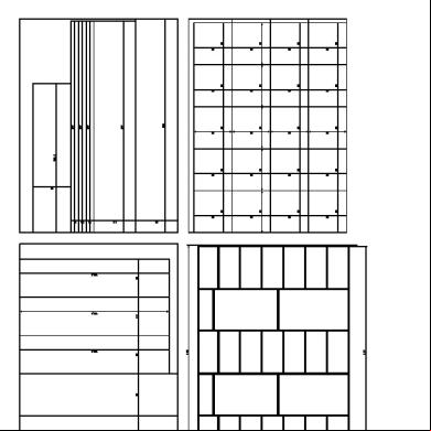
Plano Closet Mamita 5w3e4d
June 2021 0
6l6m1j
November 2019 83
Ecodrive 03 - Instruction Manual c6l1w
December 2019 78
Ejercicios De Formulacion Ocupando Metodo Grafico 4t332v
November 2020 0
Tarea Semana 4 6wl13
January 2021 0