Emerson Anderson Greenwood 82 Series Catalogue 5d5c4i
This document was ed by and they confirmed that they have the permission to share it. If you are author or own the copyright of this book, please report to us by using this report form. Report 3b7i
Overview 3e4r5l
& View Emerson Anderson Greenwood 82 Series Catalogue as PDF for free.
More details w3441
- Words: 1,010
- Pages: 4
CROSBY SERIES 82 PRESSURE RELIEF VALVES
High performance, direct spring operated pressure relief valve for natural gas applications
FEATURES • Leak-tight performance near set pressure allows higher operating pressures resulting in increased process throughput and system optimization. • 2-piece body design with easily replaceable seat and seals reduces downtime and maintenance costs. • FKM soft seat provides repeatable leak-tight performance before and after each relief cycle. • Bubble tight at 90% or better of set pressure. • Manufactured to ASME Section VIII UV for gas service. • Relieving capacities certified by National Board of Boiler and Pressure Vessel Inspectors. • Standard trim components in 316 stainless steel for maximum corrosion resistance. • Optional trim to NACE MR-0175 (2002 Edition). • Gas service only. Lift lever not available for air service.
GENERAL APPLICATION
TECHNICAL DATA
The Series 82 has a rugged construction designed specifically for high pressure multi stage natural gas compressors.
Sizes:
Emerson.com/FinalControl
© 2017 Emerson. All rights reserved.
¾” x 1" to 1" x 1" (20 x 25 mm to 25 x 25 mm) Orifices: D 0.127 in2 (0.819 cm2); E 0.221 in2 (1.423 cm2) Connections: MNPT x FNPT Temperature range: -15°F to 400°F (-26°C to 204°C) For lower temperatures consult factory. Set pressures: 15 to 1500 psig (1 to 103 barg) Code: ASME VIII
VCTDS-00806-EN 17/06
CROSBY SERIES 82 PRESSURE RELIEF VALVES
PARTS LIST
Item no. Description 1[3] Inlet bushing 2 Set screw, body 3[2] O-ring 4[2] O-ring 5 Nozzle 6[2] O-ring seat 7 Seat holder 8 Spindle 9 Guide 10 Spring washer 11 Body 12 Seal 13 Spring 14 Top insert 15[2] Gasket 16 Locknut 17[1] Screw, adjustment 18[3] Cap Nameplate (not shown) Screw, drive (not shown)
S1 - Standard material STL SA105 SST 18-8 FKM FKM SST SA479-316 FKM SST A276-316 SST SA479-316 SST SA479-316 SST SA479-316 STL SA216-WCB Lead seal and SST wire SST A313-316/631 SST 17-4 (SA564) PTFE SST SA479-316 SST SA479-316/STL SA1083 STL 108-1215 or A29-1215 Commercial aluminum SST 18-8
N1 - NACE MR01754 STL SA105 SST 18-8 FKM FKM SST SA479-316 FKM SST A276-316 SST SA479-316 SST SA479-316 SST SA479-316 STL SA216-WCB Lead seal and SST wire Inconel® X750 SST 17-4 (SA564) PTFE SST SA479-316 SST SA479-316/STL SA1083 STL 108-1215 or A29-1215 Commercial aluminum SST 18-8
MATERIALS OF CONSTRUCTION 18 17 16 15 14 10 13 12 11 10
C
9 8 7 6 5 4
NOTES 1. Adjustment screw SST SA479-316 D orifice: pressures 15 to 800 psig E orifice: pressures 15 to 310 psig STL A108/A29 ZN CO PL D orifice: pressures 801 to 1500 psig E orifice: pressures 311 to 1500 psig 2. Recommended spare parts. 3. Zinc cobalt plated. 4. NACE MR0175 (2002 Edition).
ORIFICES Size D E
PROPERTIES
Pressure range psig (barg) 15 to 1500 (1.03 to 103)
A
3 2 1 B
Area in2
cm2
0.127 0.221
0.819 1.423
Temperature limits °F (°C) -15 to 400 (-26 to 204)
Connections ANSI standard NPT Inlet Outlet ¾” or 1” 1”
Valve dimensions inches (mm) A B C 39/16 113/16 10¾ (90.5) (46.0) (273.0)
Approx. weight lb (kg) 6.9 (3.13)
2
CROSBY SERIES 82 PRESSURE RELIEF VALVES CAPACITIES
NATURAL GAS (USCS, SCFM)
Orifice area, in2
Set pressure (psig) 15 25 50 75 100 125 150 175 200 225 250 300 350 400 450 500 550 600 650 700 800 900 1000 1100 1200 1300 1400 1500
D (0.127) 83 108 176 246 316 385 455 524 594 664 733 872 1012 1151 1290 1429 1569 1708 1847 1986 2265 2543 2821 3100 3378 3657 3935 4214
E (0.221) 141 185 301 420 539 658 777 896 1015 1134 1253 1490 1728 1966 2204 2442 2679 2917 3155 3393 3869 4344 4820 5295 5771 6247 6722 7198
NATURAL GAS (Metric, Nm3/HR) Set pressure (barg) 1.1 2.0 3.0 4.0 5.0 7.0 9.0 11.0 13.0 15.0 20.0 25.0 30.0 35.0 40.0 45.0 50.0 55.0 60.0 65.0 70.0 75.0 80.0 85.0 90.0 95.0 100.0 103.4
ASME Section VIII gas certified slope (USCS, SCFM/psia) ASME Section VIII gas certified slope (metric, Nm3/hr/bara) Coefficient of discharge. Kd
Natural gas properties/conditions, USCS (NTP) Temperature, T Pressure, P Gas constant, C Ratio of specific heats, /Cv Specific gravity, SG Molecular weight, M Compressibility factor, Z
Orifice area, cm2 D E (0.819) (1.423) 137 234 190 325 255 435 319 546 384 657 514 878 644 1100 774 1322 904 1544 1033 1765 1358 2320 1683 2874 2007 3429 2332 3983 2656 4538 2981 5092 3305 5647 3630 6201 3954 6755 4279 7310 4604 7864 4928 8419 5253 8973 5577 9528 5902 10082 6226 10636 6551 11191 6772 11568
D Orifice 2.03 47.33 0.872
ASME SECTION VIII AIR (USCS, SCFM)
Orifice area, in2
Set pressure (psig) 15 25 50 75 100 125 150 175 200 225 250 300 350 400 450 500 550 600 650 700 800 900 1000 1100 1200 1300 1400 1500
D (0.127) 66 87 141 197 253 309 365 421 476 532 588 700 811 923 1035 1146 1258 1370 1481 1593 1816 2040 2263 2486 2709 2933 3156 3379
E (0.221) 113 148 242 337 433 528 624 719 814 910 1005 1196 1387 1578 1769 1960 2150 2341 2532 2723 3105 3486 3868 4250 4631 5013 5395 5777
E Orifice 3.47 80.85 0.856
60°F (20°C) 14.7 psia (1.013 bara) 344 (0.0261) 1.27 0.6 17.40 1.0
3
CROSBY SERIES 82 PRESSURE RELIEF VALVES
SELECTION GUIDE Example: Model 82
82
S1
M
1
D
V
01
-
K
0015
Series 82
Material of construction S1 Standard materials N1 NACE - MR0175-2002 Connection type M MNPT x FNPT Connection size 1
¾" MNPT x 1" FNPT [20 mm x 25 mm]
2
1" MNPT x 1" FNPT [25 mm x 25 mm]
Orifice D E
0.127 in2 [0.819 cm2] 0.221 in2 [1.423 cm2]
Seat material V
FKM
Variation 01 Standard 02 Low temperature (-20°F/-29°C) 03 Stainless steel inlet bushing 02
Low temperature (-20°F/-29°C) and SST inlet bushing
Design revision -
Dash (-) Indicates original design
Service K ASME Section VIII gas N Non code gas Set pressure 0015
15 psig
1500
1500 psig
4
Related Documents 3m3m1z

Emerson Anderson Greenwood 82 Series Catalogue 5d5c4i
January 2023 0
Anderson Greenwood Series Series 60 And 80 174b39
April 2020 29
Anderson Greenwood Manifolds 3n202k
December 2019 46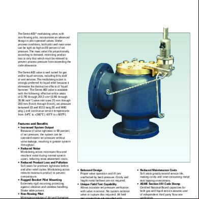
Anderson Greenwood - Pentair Series 400 Modulating Datasheet.pdf 1b6p1v
November 2022 0
Anderson Greenwood Po Psv Series 200 400 500 700 800 3g7348
November 2022 0