Gent Fire Alarm 17r4z
This document was ed by and they confirmed that they have the permission to share it. If you are author or own the copyright of this book, please report to us by using this report form. Report 3b7i
Overview 3e4r5l
& View Gent Fire Alarm as PDF for free.
More details w3441
- Words: 5,235
- Pages: 23
SECTION 4: page 1
Section 4:
Conventional Fire Detection
by Honeywell
4 SECTION 4: page 3
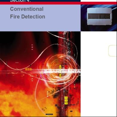
4: CONvENTIONal FIr E DETECTION
Xenex system architecture
Dual RX/TX Beam with reflect or
by Honeywell
B
B e a m
eam Tran smitt er
R e c e i v e r
24V End of Line
Call Point
Smoke Detector
Smoke Detector
3 Core Cable End of Line
Control Unit En d of Li n e
Control Unit (24V required) Sm oke Dete ctor
C all P oi nt
S mo ke Det ect or
Heat Detect or
Duc t Detect or
Ca ll Poi nt
C ont rol Pa nel (al so 1,2 ,4, 8 zo ne ver sio ns)
Repeat
Class Chang e1 N/O, 1 N/C relay s to auxiliary equipme nt such End of as door Line holders or manned centre link.
Al arm Soun der
Voice Enhanced Sounder
Voice Enhanced Sounder Strobe
Soun der Str obe
Polarised Relay (to switch 230V equipment eg. door holders)
E n d o f L i n e
Sounde rs Circuit s
S o u n d e r
End of Line
4
S t r o b e
SECTION 4: page 4
4: CONvENTIONal FIr E DETECTION by Honeywell
Xenex control
The Xenex complies fully with the
European
standard
EN 54 Parts 2 & 4 and can be used on installations meeting BS 5839-1. Each contains its own integral
power
supply
and
battery for up to eight alarm sounder circuits,
two
auxiliary relay s, a zone disablement facility and a one man test and commission facility, all simplifying system design, installation and commissioning.
Xenex Control
4 TEChNICal SpECIFICaTION No. of Zones Maximum Load per Zone
1 3mA
No. of Sounder Circuits
2 3mA
2
4 3mA
2 4 0.5A per circuit Total load not to exceed 1A
Max. Sounder Circuit Load Batteries (seperate)
Aux. Relay s Approx Weight (with batteries)
5.8 Kg
Relevant Standard Approvals
*8 Zone Repeat N/A
8
N/A N/A
2 x 12V, 2.8 Ah
2 x 12V, 2.1 Ah
Battery Standby
8 3mA
2 x 12V, 2.1 Ah
72 hours plus 0.5 hours alarm load
72 hours
1 N/O and 1 N/C pair, 1A at 24V
N/A
5.8 Kg
5.8 Kg
6.2 Kg
EN 54 Parts 2 & 4 LPCB approved to EN54: Parts 2 & 4
Cable Entry Cable Type
13 Top and 13 Rear BS 6387, 2 core, min 1.5mm2 CSA Via normally open push button switch located no more than 100m from
Class Change Facility
o
Operating Temperature
Indoor, 0 - 40 C
Note: Maximum of 1, 8 zone repeat per system. Note: For maximum system loading table see page 20.
Dimensions of all s (inc repeat ) (mm) 87
13270-01LB
2 Zone
13270-02LB
4 Zone
13270-04LB
8 Zone
13270-08LB
197
OrDEr CODES
274
19
395
1 Zone
8 Zone Repeat
13271-08LB
Flush Surround
13270-29LB
(Batteries to be ordered seperatly)
5.8 Kg
89
89
For flush mounting, aperture size 378mm x 245mm x 60mm
N/A
4: CONvENTIONal FIr E DETECTION by Honeywell
12 Zone Control s
For larger applications a 12 zone conventional is available. The
complies
with
BS 5839 and includes facilities such as one man zone test, bomb alert and zoned or two stage alarm outputs as required. For larger sizes or flush mounting
versions
please
Gent.
Zone Control
4
TEChNICal SpECIFICaTION No. of Zones
12
Maximum Load per Zone No. of Sounder Circuits
1.6mA 2 (extra sounder circuits may be added using 4 way sounder cards)
Max. Sounder Circuit Load
1A per circuit
Batteries
2 x 7Ah,12V
Battery Standby
24 hours - For 48 hour or 72 hour requirements consult Gent
Aux. Relay s All s rated at 30 Vdc 1A maximum
Common fire s - Operates on fire condition Zonal fire s - Per zone, operates on fire condition Alarm s - Operates with alarm sounders Fault s - Operates on any fault condition
Approx Weight
15kg
Cable Entry
Top and bottom
Class Change Facility
Yes
Note: If additional sounder circuits are required an extra power supply unit may be needed.
a
a 12 Zone
500
B
C
355
105 repeat 12 Zone B
C
370
295
80
4: CONvENTIONal FIr E DETECTION by Honeywell
Manual
call
Manual Call Points points
are
manufactured from ABS with plastic
covered
push
break
glasses for safe and simple operation.
No
hammer
is
required. For accessories see page 19. A polycarbonate cover version is
available
susceptible
for
applications
to
inadvertent
operation, such as sports halls.
Manual Call point
4
TEChNICal SpECIFICaTION Nominal Voltage Ingress Protection
24Vdc IP43 (IP55 with cover)
Approx Weight Operating Temperature
0.11 Kg -20oC to +70oC EN 54-11 LPCB applied for
Relevant Standard Approvals Alarm Current Colour
Pack of 5 Protective Covers
OrDEr CODES M 08
Flush
470
NO/NC* Flush Call Point
ohm 1422271160-62NM
08 Pack of 10 M S/Mount Boxes 71167-94NM
Pack of 10 Test Keys
71167-90NM S4-
34899 M Weather Resistant kit
71167-
Dimensions (mm)
95NM
M Key operated (470 ohm) 14225-
Pack of 10 Spares Glasses
30mA (max) Red (Similar to RAL 3020)
S4-34898
Pack of 10 Resetable Elements 71167-96NM
* Normally Open / Normally Close
87
87
21
Terminal block
87
Removable
8 7
21 15 15
4: CONvENTIONal FIr E DETECTION by Honeywell
Smoke Detectors
Optical smoke detectors are ideal
at
detecting
visually
smoky fires which are likely to be slow, smouldering fires. ABS casing with red LED fire indicator.
Optical Detector
Special feature The use of the
TEChNICal SpECIFICaTION Type
diode base allows monitoring of a removed detector to comply with BS 5839.
Optical
Nominal Voltage
9 - 28V dc
Quiescent Current
60μA
Ingress Protection
N.B. Maximum of 20 per zone.
IP30
Approx Weight Operating Temperature
0.11 Kg -10oC to +50oC EN 54–7 LPCB approved
Relevant Standards Approvals
Dimensions (mm)
OrDEr CODES
10
104
Optical
17840-01
Common Base
17800-02
Common Base
46
73 with base
with Diode
17801-02
Base less Diode (surface cabling)
17800-01
Base with Diode (surface cabling)
17801-01
Remote LED module
17899-01
Remote Relay module
17899-44
4
4: CONvENTIONal FIr E DETECTION by Honeywell
Heat
detectors
Heat Detectors respond
to
changes in temperature and are better suited to smoky, dusty or steamy environments than smoke detectors. A comprehensive range of fixed, high temperature and rate of rise devices are available, making the range suitable for areas where the temperature fluctuates for natural reasons or due to certain industrial processes. ABS casing with red LED fire heat
indicator. Detector
4
TEChNICal SpECIFICaTION Type Nominal Voltage
Fixed Temp. 28V dc
rate of rise 28V dc
high Fixed Temp. 24V dc
Quiescent Current Ingress Protection
30μA IP30
30μA IP30
30μA IP30
0.07 Kg
0.07 Kg
0.07 Kg
EN 54 Part 5 LPCB
-10oC to +50oC EN 54 Part 5 LPCB
EN 54 Part 8 -
58oC Grade 1
NA (Factory preset 58oC) Grade 1
85oC Grade 2
Approx Weight Operating Temperature Relevant Standards Approvals Trigger Temperature Sensitivity
OrDEr CODES Fixed Temperature
17850-01
Rate of Rise
17860-01
High Fixed Temperature
17870-01
Common Base
17800-02 Dimensions (mm)
Common 17801-02
(surface cabling)
10
Diodeless Diode Base 17800-01
Base with Diode (surface
17801-01
cabling) Remote LED module
17899-01
Remote Relay module
17899-44
44
97
Base with
4: CONvENTIONal FIr E DETECTION by Honeywell
Beam Smoke Detectors
Optical beam smoke detectors are suitable for large open areas where installation of single point detectors may be difficult or uneconomical. Beam
detectors
installed
with
transmitter
and
can
be
separate receiver
or
combined transceiver unit and reflector. Note: An additional 24V dc power supply is required.
Dual Beam
Combined reflective Detector
4
TEChNICal SpECIFICaTION Type Nominal Voltage
Dual Beam 24V dc
Combined Reflective Detector 24V dc
Quiescent Current
Receiver: - 8mA Transmitter: - 5mA
Receiver: <4mA
Approx Packaged Weight Ambient Temperature Relevant Standards Beam Length
3.2 Kg
0.67 Kg
-10oC to 50oC BS 5839-5 10m - 100m
-30oC to 55oC 50m - 100m
Dimensions (mm) Separate Beam Smoke Detector
101
95
260
65
210
85
Combined rXTX Width: 130mm height: 210mm Depth: 120mm
OrDEr CODES Beam Detector
07011-41
Reflective Beam
07011-40
SECTION 4: page 10
4: CONvENTIONal FIr E DETECTION by Honeywell
The
duct
Duct Smoke Detector
detector
kit
is
comprised of
a
detector
duct
detector
The duct detector is
mounted
and
conventional
housing. on the outside of the air duct. A venturi tube protrudes into the duct and draws a sample of the air which es over the sensor and returns back into the duct. When the smoke density in the sampled air reaches the trigger level of the smoke detector an alarm will be signalled on the fire Duct Detector
alarm control .
4
TEChNICal SpECIFICaTION Ingress Protection
IP54 -10oC to +60oC
Operating Temperature Approx Weight
0.7Kg
Finish
ABS plastic (Grey)
Air Velocity
1M/S to 20M/S
Quiescent Current
90μA
Dimensions (mm)
OrDEr CODES Duct Detector
300 17815-01
Duct Detector 781456 110
including 0.6m Venturi tube Mounting Kit For round and installed air ducts
781459
Remote Relay Module
17899-44
Optical Smoke Detector
17840-01
120
4: CONvENTIONal FIr E DETECTION
S3 Electronic Sounders / Strobes
by Honeywell
The S-cubed range of alarm sounders
incorporate
sound,
speech and strobe effects all in one range of alarm devices. The range offers all variants in the choice of 2 colours, red or white, with either a shallow base version sealed to IP31 or a deep base version sealed to IP55. All the low profile sounders have the option of an integral strobe. As an aid to
commissioning
there is the option to use the HandiLink IR remote control to select sounder tones and adjust TEChNICal SpECIFICaTION – 1.0. SOuNDErS aND STrOBES Type Sounder Sounder/Strobe
Strobe Only
the volume remotely. This means
physical access is not requiredSee to Tone make this adjustment. ThisTable facility is only activeN/A when the sounders are turned on from the fire alarm Sound Output at 1m Table See Tone Strobe Flash Rate See Tone Table See Tone Table Variable . N/A
Equivalent to a 3w Xenon Strobe
Equivalent to a 3w Xenon Strobe
See Tone Table
See Tone Table
6 mA @ 24V
Strobe Output Average Current Synchronisation Operating Voltage Range
Sound & Strobe synchronisation better than ±30mS over 20 minutes with all units powered from the same circuit 10.8V – 28.8V
Ingress Protection Approx Weight Operating Temperature Relevant Standards (Sounder only)
10.8V – 28.8V
10.8V – 28.8V
IP55C with the Deep Base IP31C with the Shallow Base 0.3Kg 0.3Kg 0.3Kg -10oC to 50oC
-10oC to 50oC
-10oC to 50oC
EN54-3
EN54-3
N/A
IR Control Operating Distance
3m
3m
N/A
Standards Complies with EN54 ◆ Very low power consumption means more sounders and strobes perPt3 circuit
◆ The strobe option is equivalent to a standard 3w xenon strobe and uses 1/20th of the power ◆ 32 sounder tones are available ◆ Voice enhanced sounders are available in the range ◆ 4 voice phrases and a bell sound are available as standard ◆ All sound and strobe signals are synchronised to better than +/- 30mS over 20 minutes ◆ Sounders and Strobes are compatible with 12V and 24V systems ◆ A third wire option allows the selection of 2 alternative sounds. Ideal for class change applications ◆ Products incorporate innovative design features for which multiple patents have been granted
OrDEr CODES Ip31 low profile Sounders Sounder/Strobe Red
C3-SN-ST-RR
Sounder/Strobe White
C3-SN-ST-WR
Sounder Red
C3-SN-R
Sounder White
C3-SN-W
Ip55 low profile Sounders Sounder/Strobe Red
C3IP-SN-ST-RR
Sounder/Strobe White
C3IP-SN-ST-WR
Sounder Red
C3IP-SN-R
Sounder White
C3IP-SN-W
Sounder Red Body/White Lens C3IP-SN-STRW Ip55
Strobe
only
Strobe Red Body/Red Lens
C2IP-ST-RR
remote Control HandiLink IR Remote Control
S3-CONTROL
Please note – all strobes are red except where listed
4
4: CONvENTIONal FIr E DETECTION by Honeywell
S3 Electronic Sounders / Strobes
TONE TaBlE FOr SOuNDEr ONly aND SOuNDEr / STrOBE varIaNTS
Signal 1 Tone 1 Tone 2 Tone 3
1Hz 1Hz
Alternating tone 800/ 970Hz @ 1Hz - BS 5839: Part 1
1Hz 1Hz
Tone 5
0.8Hz
Tone 6
1Hz
Tone 8 Tone 9 Tone 10 Tone 11 Tone 12
Description Alternating tone 800/ 970Hz @ 2Hz FP 1063.1 Telecoms BS 5839: Part 1
Tone 4
Tone 7
4
Strobe
0.5Hz
Intermittent tone 970Hz @ 1Hz LF back up alarm - BS 5839: Part 1 Intermittent tone 2850Hz @ 1Hz HF back up alarm - 2nd tone BS 5839: Part 1 Intermittent tone 970Hz 0.25s - on, 1s off - BS 5839: Part 1 Continuous @ 970Hz - BS 5839: Part 1 Slow sweep 300Hz- 1200Hz over 2s - Vds2300 Signal
SW1 Switch
7.4
101.8
9.5
101.7
16.5
7.3
101.7
Signal 3
Strobe
3.4
Tone 3
0.5Hz
Tone 6
1Hz
9.5
3.4
Tone 3
0.5Hz
Tone 6
1Hz
3 2
1
6
5
4
3 2
1
101.6
15.5
4.5
101.6
8.2
2.0
Tone 5
0.8Hz
Tone 6
1Hz
6
5
4
3
1
103.7
15.8
5.5
103.7
8.5
2.5
Tone 3
0.5Hz
Tone 6
1Hz
6
5
4
3 2
1
101.2
12.0
2.0
101.4
6.0
1.0
Tone 2
0.5Hz
Tone 6
1Hz
6
5
4
3 2
1
102.0
16.5
8.0
102.1
9.8
3.7
Tone 3
0.5Hz
Tone 1
1Hz
6
5
4
99.3
13.0
7.9
99.3
7.0
3.7
Tone 3
0.5Hz
Tone 6
1Hz
5
93.5
16.3
8.2
93.7
9.4
3.7
Tone 3
0.5Hz
Tone 6
1Hz
94.1
16.5
8.7
94.3
9.5
4.0
Tone 3
0.5Hz
Tone 6
1Hz
104.4
16.5
9.7
104.7
10.2
4.4
Tone 3
0.5Hz
Tone 6
1Hz
100.2
16.5
11.2
100.8
10.6
5.4
Tone 12
0.5Hz
Tone 10
1Hz
101.9
16.5
12.0
102.7
11.5
5.8
Tone 3
0.5Hz
Tone 10
1Hz
ON
3
2
2
1
4
3 2
1
6
5
4
3 2
1
1Hz
Medium sweep 800Hz - 970Hz @ 1Hz - BS 5839: Part 1
6
5
4
3 2
1
6
5
4
3 2
1
6
5
6
5
6
5
6
Continuous @ 2850Hz Sweep 2400 - 2850Hz @ 7Hz
4
3
2
1
Sweep 2400 - 2850Hz @ 1Hz Slow whoop 500Hz - 1200Hz over 3s with 0.5s off Sweep 1200Hz @ 1200Hz - 500Hz @ 1Hz with 10ms silence - German DIN tone evacuate
16.5
Strobe
4
Fast sweep 800Hz - 970Hz @ 7Hz - BS 5839: Part 1
1Hz
101.8
Signal 2
5
1Hz
1Hz
24V Operating Current dB(A) @1m With Strobe Without mA Strobe mA
6
ON
6
1Hz
Graphical representation
12V Operating Current dB(A) @1m With Strobe Without mA Strobe mA
4
3 2
1
4
3 2
1
98.8
15.5
7.5
99.2
8.7
3.5
Tone 3
0.5Hz
Tone 6
1Hz
5
4
3 2
1
96.6
16.2
7.3
98.1
9.5
3.5
Tone 3
0.5Hz
Tone 6
1Hz
Tone 13
0.86Hz
Tone 14
1Hz
Tone 15
1Hz
Alternating tone 2400/ 2850Hz @ 2Hz
6
5
4
3 2
1
101.7
16.5
12.0
102.5
11.8
6.2
Tone 12
0.5Hz
Tone 10
1Hz
Tone 16
1Hz
Alternating tone 554Hz for 100mS then 440Hz for 400ms - French AFNOR tone
6
5
4
3 2
1
89.3
15.8
5.2
89.6
8.7
2.5
Tone 3
0.5Hz
Tone 6
1Hz
1Hz
Alternating tone 440Hz / 554Hz @ 2Hz - Turn out Sweden
6
5
4
3 2
1
90.1
15.8
5.7
90.3
8.9
2.8
Tone 19
0.5Hz
Tone 18
1Hz
6
5
4
3 2
1
95.9
16.2
7.0
96.3
9.8
3.3
Tone 1
0.5Hz
Tone 3
1Hz
6
5
4
3 2
1
95.9
6.1
4.0
96.3
5.0
2.3
Tone 17
0.5Hz
Tone 18
1Hz
6
5
4
3 2
1
100.6
15.5
5.8
101.0
8.5
2.7
Tone 17
0.5Hz
Tone 25
1Hz
6
5
4
3 2
1
100.9
16.0
10.0
101.2
10.0
4.0
Tone 3
0.5Hz
Tone 6
1Hz
6
5
4
3 2
1
Tone 6
1Hz
Tone 17 Tone 18
1Hz
1Hz
Rising 1s, constant 4s, fall 1s @ 1000Hz - Industrial alarm
1Hz Intermittent tone 700Hz 4s On , 4s Off Tone 22 4s - On 4s - Industrial alarm - Off Tone 23 Tone 24 Tone 25
Sync. pulses 1Hz 1Hz
ON
Continuous 700Hz - All clear Sweden
1Hz Intermittent tone 700Hz 6s On 12s Off Tone 19 6s - On - Pre- vital message Sweden 12s - Off Intermittent tone 1000Hz @ 1Hz Tone 20 1Hz Local warning Sweden Tone 21
ON
Emergency evacuation to ISO 8201 - ISO 8201 Tone Slow whoop 500Hz - 1000Hz over 4.5s - Evacuate Netherlands Siren (ramp up from 500Hz - 1200Hz in 3s then ramp down 1200Hz - 500Hz in 3s)
Tone 26
1Hz
Tone 27
Sync. pulses
US temporal tone LF
Tone 28
Sync. pulses
US temporal tone HF
Tone 29
1Hz
101.4
8.7
5.7
101.9
6.4
3.0
Tone 19
0.5Hz 6s - On 12s - Off
1
104.0
12.0
4.0
104.5
6.0
1.5
Tone 3
0.5Hz
Tone 6
1Hz
3 2
1
99.6
16.0
7.2
100.2
9.5
3.4
Tone 3
0.5Hz
Tone 6
1Hz
3 2
1
98.2
16.0
7.5
98.5
9.5
3.5
Tone 3
0.5Hz
Tone 6
1Hz
4
3 2
1
95.8
15.8
7.0
96.0
8.7
3.3
Tone 24
0.5Hz
Tone 25
1Hz
5
4
3 2
1
100.6
12.0
3.0
100.6
5.5
1.0
Tone 3
0.5Hz
Tone 6
1Hz
6
5
4
3 2
1
6
5
4
3 2
1
99.0
11.8
2.5
99.0
5.3
0.8
Tone 4
0.5Hz
Tone 6
1Hz
6
5
4
3 2
1
98.8
16.3
9.4
99.2
10.0
4.3
Tone 3
0.5Hz
Tone 6
1Hz
102.2
10.8
6.4
Tone 3
0.5Hz
Tone 31
1Hz
102.0
10.8
6.4
Tone 3
0.5Hz
Tone 8
1Hz
99.2
9.5
3.5
Tone 3
0.5Hz
Tone 6
1Hz
6
5
4
3 2
1
6
5
4
3 2
6
5
4
6
5
4
6
5
6
ON
Fast whoop 500Hz - 1000Hz @ 7Hz
LF buzz 800Hz- 970Hz @ 50Hz
ON
Alternate 2500/ 3100 @ 2Hz - Security 6 5 4 3 2 1 Tone 30 1Hz 101.6 16.5 13.0 alarm Note: The current data in the table is for Red strobe only. Tonenominal 31 1Hz 2500 /stated 3100 @in4Hz 101.2 of the 16.5 13.0 The sound Alternate frequencies the table are based on the resonance frequency transducer. ON
Tone 1 is the factory default Define duringsetting manufacture - default is Tone 32 1Hz a fast siren
98.8
16.0
7.5
SECTION 4: page 13
4: CONvENTIONal FIr E DETECTION
S3 Voice Enhanced Sounders
by Honeywell
how to select a speech message and attention TEChNICal SpECIFICaTION – 1.1 vOICE ENhaNCED SOuNDErStone & STrOBES Type
voice Enhanced Sounder
voice Enhanced 1. SelectSounder/Strobe the required speech message and tone from the signal See Table 3 1 column of table 3 referring to See Table 3 table 1 and 2 for message and
Sound Output at 1m Strobe Flash Rate
See Table 3 See Table 3
Strobe Output Average Current
Equivalent to a 3w Xenon Strobe See Table 3 See Table 3
Sound & Strobe synchronisation better than ± 30mS over 20 minutes with all units powered from the same circuit
Synchronisation Message and Attention Tone Period
10-30 Seconds
10-30 Seconds
Operating Voltage Range Maximum Reverse Monitoring Voltage
10.8V – 28.8V
10.8V – 28.8V
30V/20μA
30V/20μA
Ingress Protection Approx Weight
IP55C with the Deep Base IP31C with the Shallow Base 0.3 Kg 0.3 Kg
Operating Temperature -10oC to 50oC CONvENTIONal SpEECh SOuNDEr aND STrOBE IR Control Operating Distance 3m Table 1 Message No. Speech Message
-10oC to 50oC 3m
tone descriptions. 2. If the third wire option is used the two alternative messages and ones for your first selection are shown on the right hand side of table 3. 3. After making a selection set the switch SW1 as shown in the SW1 column of table 3.
4
M1 M2
Attention please this is an emergency please leave the building by the nearest available exit. (Female voice) An incident has been reported in this building please await further instructions. (Female voice)
M3 M4
This is a test message no action is required. (Female voice) This is a fire alarm! Please leave the building immediately by the nearest available exit. (Male voice)
Complex Tone No.
Description of Tone
CTO
Alarm Bell (equivalent to 8” Solenoid Bell) 12V 105dB(A) @ 1m with strobe 14.2mA (without strobe 4.5mA) 24V 105.5dB(A) @ 1m with strobe 12mA (without strobe 4.5mA) Standard messages and complex tones (Audio File - PA020001)
Table 2 Graphical representation
Tone
Description
Tone 1
Alternating tone 800/ 970Hz @ 2Hz – FP 1063.1 Telecoms
Tone 2
Intermittent tone 970Hz @ 1Hz LF back up alarm – BS 5839: Part 1
Tone 3
Intermittent tone 970Hz 0.25s on, 1s off – BS 5839: Part 1
Tone 4
Continuous @ 970Hz - BS 5839: Part 1
Tone 5
Fast sweep 800Hz – 970Hz @ 7Hz – BS 5839: Part 1
Tone 6
Medium sweep 800Hz – 970Hz @ 1Hz – BS 5839: Part 1
Tone 7
Sweep 1200Hz @ 1200Hz -– 500Hz @ 1Hz with 10ms silence – German DIN tone evacuate
Tone 8
Alternating tone 440Hz / 554Hz @ 2Hz – Turn out Sweden
Tone 9
Intermittent tone 1000Hz @ 1Hz – Local warning Sweden
Tone 10
Intermittent Tone 700Hz 4s On, 4s Off – Industrial alarm
Tone 11
Fast whoop 500Hz – 1000Hz @ 7Hz
Voice Sounder/Strobe White C3-VP-ST-WR
Tone 12
US temporal tone LF
Ip55 low profile Sounders
Tone 13
US temporal tone HF
Voice Sounder Red R
Tone 14
Define during manufacture – default is a fast siren
Voice Sounder White
OrDEr CODES Ip31 low Sounders
profile
Voice Sounder Red R
C3 -VP-
Voice Sounder White
C3-VP-W
Voice Sounder/Strobe Red C3-VP-ST-RR
C3IP-VPC3IP-VP-W
Voice Sounder/Strobe Red C3IP-VP-ST-RR Note: Only the messages and complex tones specified in table 1 are applicable to this S-cubed product. Note: The nominal sound frequencies stated in the table are based on the resonance frequency of the transducer.
Voice Sounder/Strobe White C3IP-VP-ST-WR remote
Control
HandiLink IR Remote Control
S3-CONTROL
4: CONvENTIONal FIr E DETECTION by Honeywell
S3 Voice Enhanced Sounders
aTTENTION TONE FOllOWED By SpEECh MESSagES
TaBlE 3 – TONE / vOICE TaBlE FOr vOICE aND vOICE / STrOBE varIaNTS Decibel (dBA) and current (mA) values
Signal 1 Message
Strobe
Attention Tone
M1
1Hz
Tone 1
M1
1Hz
Tone 6
Tone 2
M3
1Hz
Tone 4 Tone 4
6
5
4
3 2
1
95.8
15.8
7.0
96.0
8.7
3.3
Tone 5
0.8Hz
Tone 6
M3
1Hz
Tone 4
1
93.5
16.3
8.2
93.7
9.4
3.7
Tone 3
0.5Hz
Tone 6
M3
1Hz
Tone 4
90.1
15.8
5.7
90.3
8.9
2.8
Tone 2
0.5Hz
Tone 6
M3
1Hz
Tone 4
96.6
16.2
7.3
98.1
5.5
1.0
Tone 3
0.5Hz
Tone 1
M3
1Hz
Tone 4
98.8
16.0
7.5
99.2
9.5
3.5
Tone 3
0.5Hz
Tone 6
M3
1Hz
Tone 4
101.8
16.5
7.4
101.8
9.5
3.4
Tone 3
0.5Hz
Tone 6
M3
1Hz
Tone 14
94.1
16.5
8.7
96.0
8.7
3.3
Tone 3
0.5Hz
Tone 6
M6
1Hz
Tone 4
93.5
16.3
8.2
93.7
9.4
3.7
Tone 3
0.5Hz
Tone 6
M6
1Hz
Tone 4
90.1
15.8
5.7
90.3
8.9
2.8
Tone 12
0.5Hz
Tone 10
M6
1Hz
Tone 4
96.6
16.2
7.3
98.1
9.5
3.5
Tone 3
0.5Hz
Tone 10
M6
1Hz
Tone 4
3 2
1
M1
1Hz
Tone 7
6
5
4
3 2
1
ON
6
5 4
6
5
6
3
2
2
1
4
3 2
1
5
4
3 2
1
6
5
4
3 2
1
6
5 4
3 2
1
6
5
6
5
Tone 14 Tone 1 Tone 6 Tone 11
4
3
2
1
4
3 2
1
5 4
3 2
1
100.6
12.0
3.0
100.6
5.5
1.0
Tone 3
0.5Hz
Tone 6
M6
1Hz
Tone 4
5 4
3 2
1
98.8
16.0
7.5
99.2
9.5
3.5
Tone 3
0.5Hz
Tone 6
M6
1Hz
Tone 4
6
5
4
3 2
1
Tone 12
0.5Hz
Tone 10
M6
1Hz
Tone 4
6
5
4
3 2
1
Tone 3
0.5Hz
Tone 6
M3
1Hz
Tone 14
6
5
4
3 2
1
Tone 19
0.5Hz
Tone 18
M3
1Hz
CT0
6
5
4
3 2
1
Tone 1
0.5Hz
Tone 3
M3
1Hz
CT1
6
5
4
3 2
1
Tone 17
0.5Hz
Tone 18
M3
1Hz
CT2
6
5
4
3 2
1
6
5
4
3 2
1
Tone 17
0.5Hz
Tone 25
M3
1Hz
CT3
6
5
4
3 2
1
Tone 3
0.5Hz
Tone 6
M3
1Hz
CT4
Tone 6
M3
1Hz
CT5
Tone 6
M3
1Hz
CT6
ON
Tone 8
0.5Hz
1Hz
4
1Hz
M2
M3
5
M4
3.4
Tone 3
6
Tone 5
9.5
0.5Hz
Tone 8
1Hz
101.8
M2
1Hz
M4
7.4
4.0
M1
1Hz
16.5
9.5
3
M4
101.8
94.3
5 4
1Hz
Attention Tone
8.7
6
M4
Strobe
16.5
Tone 5
1Hz
Signal 3 Message
94.1
1Hz
1Hz
Attention Tone
1
M1
M1
Strobe
3 2
Tone 11
Tone 12
Signal 2 Message
4
1Hz
1Hz
Intermittent 1S On and 1S Off Without Strobe mA
5
M1
M1
24V Without With Strobe Strobe mA dB(A) @1m mA
6
ON
M4
4
SW1 Switch
12V With Strobe dB(A) @1m mA
6
ON
M4
1Hz
Tone 7
6
ON
M4 M4 M1 M1 M1
1Hz 1Hz 1Hz 1Hz 1Hz
Tone 12 Tone 14 CT0 CT1 CT2
M1
1Hz
CT3
M1
1Hz
CT4
M1
1Hz
CT5
6
5
4
3 2
1
CT6
6
5
4
3 2
1
6
5
4
3 2
1
6
5
4
3 2
1
6
5
4
3 2
1
6
5
4
3 2
1
6
5
4
3 2
1
6
5
4
3 2
1
6
5
4
3 2
1
6
5
4
3 2
1
Tone 3
0.5Hz 6s On 12s Off 0.5Hz
Tone 3
0.5Hz
Tone 6
M3
1Hz
CT7
Tone 3
0.5Hz
Tone 6
-
1Hz
CT0
Tone 24
0.5Hz
Tone 25
-
1Hz
CT1
Tone 3
0.5Hz
Tone 6
-
1Hz
CT2
Tone 4
0.5Hz
Tone 6
-
1Hz
CT3
Tone 3
0.5Hz
Tone 6
-
1Hz
CT4
1Hz CT5 Note: Only the complex tones (CTn) and speech messages (Mn) specified in Table 1 are
Tone 3
0.5Hz
Tone 31
-
1Hz
CT5
valid. -The highlighted this table shows the factory default setting of the S-cubed 1Hz row in CT6
Tone 3
0.5Hz
Tone 8
-
1Hz
CT6
Tone 3
0.5Hz
Tone 6
-
1Hz
CT7
M1 M1
1Hz 1Hz
CT7
ON
TONE ONly
-
1Hz 1Hz
Tone 19 Refer to decibel (dBA) and current (mA) values stated in Table 1.
CT0 CT1
-
1Hz
CT2
-
1Hz
CT3
-
1Hz
CT4
ON
ON
unit. -
1Hz
CT7
4: CONvENTIONal FIr E DETECTION by Honeywell
Bells
An electronic bell for a wide range of uses. Metal casing available in red or grey finish. Suitable for semi flush or surface mounting.
Bell
4
TEChNICal SpECIFICaTION Type Ingress Protection Approx Weight
24V dc
230V ac
Standard IP40
Standard IP41
Special IP55
Special IP55
1.1 Kg
1.25 Kg Indoor, -10oC to +50oC
Operating Temperature Sound Output at 1m
93dB(A)
Current at Nominal Voltage
96dB(A)
30mA
Relevant Standard
30mA EN 54-3
Dimensions (mm)
155
85
130
155
OrDEr CODES 24V dc Bell, Red
12141-04
24V dc Bell, Red, IP55
12143-04
230V ac Bell, Grey
12142-59
230V ac Bell, Grey IP55
12144-59
4: CONvENTIONal FIr E DETECTION by Honeywell
Door Release
To ensure fire doors close in an emergency and prevent the spread of fire and smoke. Moulded
ABS
and
steel
enclosure capable of floor or wall mounting. Complies with BS 5839-3.
Door holder
4
TEChNICal SpECIFICaTION Type
Wall Mounted 24V dc
Approx Weight Current Consumption
21mA
Wall Mounted 230V ac
Door plate, 0.07 Kg Door holder, 0.53 Kg 12mA Indoor/Outdoor, -10oC to + o C 11250 Newton
Operating Temperature Nominal Magnetic Pull Relevent Standard Finish
Floor Mounted 24V dc 45mA
200 Newton
BS 5839- 3 Moulded ABS
Dimensions (mm)
96
24V dc Door Holder c/w door plate
72 dia
OrDEr CODES 04390-31
230V ac Door Holder c/w door plate
04390-55
Door Holder Floor Plate
04390-92
24V dc Relay
19107-52
Door Holder Floor Mounted
04390-41
23 96
45
4: CONvENTIONal FIr E DETECTION by Honeywell
Relays Relay
enclosure
to
house
applications involving switching and timers. All
purpose
polycarbonate
construction. Suitable
for
activating
class
change or ‘start work’ signals.
low profile Enclosure
4 TEChNICal SpECIFICaTION Coil Voltage
24V dc
Coil Current Rating 240V ac
50mA 6A
Rating 24V dc Profile
5A High
Max. Capacity Ingress Protection
4 mini relays IP67 Indoor/Outdoor, 0 - 40oC
Operating Temperature
50
125
Dimensions (mm)
OrDEr CODES
125
75
25
24V dc Relay c/w enclosure
19107-52
High Profile Enclosure
19100-02
24V dc Relay
19104-52
24V dc Timer
19106-02
4: CONvENTIONal FIr E DETECTION by Honeywell
Power Supplies
To supply additional standby power for control s or relays. Protected against over-voltage and reverse polarity connections. Fault monitoring to comply with BS 5839.
power Supply unit (O5216-24)
4
TEChNICal SpECIFICaTION Mains Input Output Current
230V ac 6A
Output Voltage Operating Temperature
230V ac 1A
27.5V dc -10o to +40oC 2 x 12V/24Ah 8.5 Kg
Max. Battery Capacity Approx Weight
-10o to +50oC 2 x 12V/7Ah 7.5Kg
380
Dimensions (mm)
OrDEr CODES power Supply units (less cells) 24V, 6.0A charger 24V, 1A Charger
05216-24 621028
408
190
4: CONvENTIONal FIr E DETECTION by Honeywell
Accessories Key Box
OrDEr CODES
A neat circular enclosure in which a key can
Key Box
08205-00
be kept for use in emergencies.
10 Spare Glasses (Plain)
4144-007
Particularly suitable for buildings where there
10 Spare Glasses (Printed)
4144-088
is a need for unsupervised emergency exits to be kept locked. Accommodates keys up to 75mm long.
OrDEr CODES
Spares Test Keys
For testing call points
without breaking the glass. resetable Element Allowing a break glass call point to be modified into a resetable call point.
Pack of 10 M S/Mount Boxes
71167-94NM
Pack of 10 Spares Glasses
71167-90NM
Pack of 10 Test Keys
S4-34899
Pack of 10 Resetable Elements
71167-96NM
Pack of 5 Protective Covers
71167-95NM
4
SECTION 4: page 20
4: CONvENTIONal FIr E DETECTION by Honeywell
System Loading Calculator
Zone Loading To calculate the zone loading of any system complete the table below and ensure that the grand total does not exceed system limits (Xenex is 3mA per zone). NO. (a)
QuIESCENT lOaD (µa) (b)
Ionisation Smoke Detector Optical Smoke Detector
15 60
Fixed Temperature Heat Detector
30
Rate of Rise Heat Detector
30
High Temperature Heat Detector 24V dc Duct Detector
30 90
TOTal lOaD (µa) (a x b)
Grand Total Notes: 1. If detector removal monitoring is required to comply with BS 5839, a detector base with diode should be used and the maximum number of detectors should not exceed 20 per zone. 2. Any number of manual call points may be included in zone calculations. 3. Beam detectors will require a separate power supply.
Sounder Circuit Loading To calculate the maximum sounder loading complete the table below and ensure that the grand total does not exceed system limits. (For Xenex; maximum load per circuit is 0.5A. Total load maximum 1A).
NO. (a) S3 Sounders and Strobes
OpEraTINg CurrENT (ma) (b)
TOTal lOaD (ma) (a x b)
*
Sounder Base 24V dc Bell
18 30
24V dc Xenon (Low current)
45 Grand Total
*See tone table for specific operating currents (page 4 section 12). Note: 1. Sirens will require a separate power supply. 2. Xenon flashers may require a separate power supply.
Section 4:
Conventional Fire Detection
by Honeywell
4 SECTION 4: page 3
4: CONvENTIONal FIr E DETECTION
Xenex system architecture
Dual RX/TX Beam with reflect or
by Honeywell
B
B e a m
eam Tran smitt er
R e c e i v e r
24V End of Line
Call Point
Smoke Detector
Smoke Detector
3 Core Cable End of Line
Control Unit En d of Li n e
Control Unit (24V required) Sm oke Dete ctor
C all P oi nt
S mo ke Det ect or
Heat Detect or
Duc t Detect or
Ca ll Poi nt
C ont rol Pa nel (al so 1,2 ,4, 8 zo ne ver sio ns)
Repeat
Class Chang e1 N/O, 1 N/C relay s to auxiliary equipme nt such End of as door Line holders or manned centre link.
Al arm Soun der
Voice Enhanced Sounder
Voice Enhanced Sounder Strobe
Soun der Str obe
Polarised Relay (to switch 230V equipment eg. door holders)
E n d o f L i n e
Sounde rs Circuit s
S o u n d e r
End of Line
4
S t r o b e
SECTION 4: page 4
4: CONvENTIONal FIr E DETECTION by Honeywell
Xenex control
The Xenex complies fully with the
European
standard
EN 54 Parts 2 & 4 and can be used on installations meeting BS 5839-1. Each contains its own integral
power
supply
and
battery for up to eight alarm sounder circuits,
two
auxiliary relay s, a zone disablement facility and a one man test and commission facility, all simplifying system design, installation and commissioning.
Xenex Control
4 TEChNICal SpECIFICaTION No. of Zones Maximum Load per Zone
1 3mA
No. of Sounder Circuits
2 3mA
2
4 3mA
2 4 0.5A per circuit Total load not to exceed 1A
Max. Sounder Circuit Load Batteries (seperate)
Aux. Relay s Approx Weight (with batteries)
5.8 Kg
Relevant Standard Approvals
*8 Zone Repeat N/A
8
N/A N/A
2 x 12V, 2.8 Ah
2 x 12V, 2.1 Ah
Battery Standby
8 3mA
2 x 12V, 2.1 Ah
72 hours plus 0.5 hours alarm load
72 hours
1 N/O and 1 N/C pair, 1A at 24V
N/A
5.8 Kg
5.8 Kg
6.2 Kg
EN 54 Parts 2 & 4 LPCB approved to EN54: Parts 2 & 4
Cable Entry Cable Type
13 Top and 13 Rear BS 6387, 2 core, min 1.5mm2 CSA Via normally open push button switch located no more than 100m from
Class Change Facility
o
Operating Temperature
Indoor, 0 - 40 C
Note: Maximum of 1, 8 zone repeat per system. Note: For maximum system loading table see page 20.
Dimensions of all s (inc repeat ) (mm) 87
13270-01LB
2 Zone
13270-02LB
4 Zone
13270-04LB
8 Zone
13270-08LB
197
OrDEr CODES
274
19
395
1 Zone
8 Zone Repeat
13271-08LB
Flush Surround
13270-29LB
(Batteries to be ordered seperatly)
5.8 Kg
89
89
For flush mounting, aperture size 378mm x 245mm x 60mm
N/A
4: CONvENTIONal FIr E DETECTION by Honeywell
12 Zone Control s
For larger applications a 12 zone conventional is available. The
complies
with
BS 5839 and includes facilities such as one man zone test, bomb alert and zoned or two stage alarm outputs as required. For larger sizes or flush mounting
versions
please
Gent.
Zone Control
4
TEChNICal SpECIFICaTION No. of Zones
12
Maximum Load per Zone No. of Sounder Circuits
1.6mA 2 (extra sounder circuits may be added using 4 way sounder cards)
Max. Sounder Circuit Load
1A per circuit
Batteries
2 x 7Ah,12V
Battery Standby
24 hours - For 48 hour or 72 hour requirements consult Gent
Aux. Relay s All s rated at 30 Vdc 1A maximum
Common fire s - Operates on fire condition Zonal fire s - Per zone, operates on fire condition Alarm s - Operates with alarm sounders Fault s - Operates on any fault condition
Approx Weight
15kg
Cable Entry
Top and bottom
Class Change Facility
Yes
Note: If additional sounder circuits are required an extra power supply unit may be needed.
a
a 12 Zone
500
B
C
355
105 repeat 12 Zone B
C
370
295
80
4: CONvENTIONal FIr E DETECTION by Honeywell
Manual
call
Manual Call Points points
are
manufactured from ABS with plastic
covered
push
break
glasses for safe and simple operation.
No
hammer
is
required. For accessories see page 19. A polycarbonate cover version is
available
susceptible
for
applications
to
inadvertent
operation, such as sports halls.
Manual Call point
4
TEChNICal SpECIFICaTION Nominal Voltage Ingress Protection
24Vdc IP43 (IP55 with cover)
Approx Weight Operating Temperature
0.11 Kg -20oC to +70oC EN 54-11 LPCB applied for
Relevant Standard Approvals Alarm Current Colour
Pack of 5 Protective Covers
OrDEr CODES M 08
Flush
470
NO/NC* Flush Call Point
ohm 1422271160-62NM
08 Pack of 10 M S/Mount Boxes 71167-94NM
Pack of 10 Test Keys
71167-90NM S4-
34899 M Weather Resistant kit
71167-
Dimensions (mm)
95NM
M Key operated (470 ohm) 14225-
Pack of 10 Spares Glasses
30mA (max) Red (Similar to RAL 3020)
S4-34898
Pack of 10 Resetable Elements 71167-96NM
* Normally Open / Normally Close
87
87
21
Terminal block
87
Removable
8 7
21 15 15
4: CONvENTIONal FIr E DETECTION by Honeywell
Smoke Detectors
Optical smoke detectors are ideal
at
detecting
visually
smoky fires which are likely to be slow, smouldering fires. ABS casing with red LED fire indicator.
Optical Detector
Special feature The use of the
TEChNICal SpECIFICaTION Type
diode base allows monitoring of a removed detector to comply with BS 5839.
Optical
Nominal Voltage
9 - 28V dc
Quiescent Current
60μA
Ingress Protection
N.B. Maximum of 20 per zone.
IP30
Approx Weight Operating Temperature
0.11 Kg -10oC to +50oC EN 54–7 LPCB approved
Relevant Standards Approvals
Dimensions (mm)
OrDEr CODES
10
104
Optical
17840-01
Common Base
17800-02
Common Base
46
73 with base
with Diode
17801-02
Base less Diode (surface cabling)
17800-01
Base with Diode (surface cabling)
17801-01
Remote LED module
17899-01
Remote Relay module
17899-44
4
4: CONvENTIONal FIr E DETECTION by Honeywell
Heat
detectors
Heat Detectors respond
to
changes in temperature and are better suited to smoky, dusty or steamy environments than smoke detectors. A comprehensive range of fixed, high temperature and rate of rise devices are available, making the range suitable for areas where the temperature fluctuates for natural reasons or due to certain industrial processes. ABS casing with red LED fire heat
indicator. Detector
4
TEChNICal SpECIFICaTION Type Nominal Voltage
Fixed Temp. 28V dc
rate of rise 28V dc
high Fixed Temp. 24V dc
Quiescent Current Ingress Protection
30μA IP30
30μA IP30
30μA IP30
0.07 Kg
0.07 Kg
0.07 Kg
EN 54 Part 5 LPCB
-10oC to +50oC EN 54 Part 5 LPCB
EN 54 Part 8 -
58oC Grade 1
NA (Factory preset 58oC) Grade 1
85oC Grade 2
Approx Weight Operating Temperature Relevant Standards Approvals Trigger Temperature Sensitivity
OrDEr CODES Fixed Temperature
17850-01
Rate of Rise
17860-01
High Fixed Temperature
17870-01
Common Base
17800-02 Dimensions (mm)
Common 17801-02
(surface cabling)
10
Diodeless Diode Base 17800-01
Base with Diode (surface
17801-01
cabling) Remote LED module
17899-01
Remote Relay module
17899-44
44
97
Base with
4: CONvENTIONal FIr E DETECTION by Honeywell
Beam Smoke Detectors
Optical beam smoke detectors are suitable for large open areas where installation of single point detectors may be difficult or uneconomical. Beam
detectors
installed
with
transmitter
and
can
be
separate receiver
or
combined transceiver unit and reflector. Note: An additional 24V dc power supply is required.
Dual Beam
Combined reflective Detector
4
TEChNICal SpECIFICaTION Type Nominal Voltage
Dual Beam 24V dc
Combined Reflective Detector 24V dc
Quiescent Current
Receiver: - 8mA Transmitter: - 5mA
Receiver: <4mA
Approx Packaged Weight Ambient Temperature Relevant Standards Beam Length
3.2 Kg
0.67 Kg
-10oC to 50oC BS 5839-5 10m - 100m
-30oC to 55oC 50m - 100m
Dimensions (mm) Separate Beam Smoke Detector
101
95
260
65
210
85
Combined rXTX Width: 130mm height: 210mm Depth: 120mm
OrDEr CODES Beam Detector
07011-41
Reflective Beam
07011-40
SECTION 4: page 10
4: CONvENTIONal FIr E DETECTION by Honeywell
The
duct
Duct Smoke Detector
detector
kit
is
comprised of
a
detector
duct
detector
The duct detector is
mounted
and
conventional
housing. on the outside of the air duct. A venturi tube protrudes into the duct and draws a sample of the air which es over the sensor and returns back into the duct. When the smoke density in the sampled air reaches the trigger level of the smoke detector an alarm will be signalled on the fire Duct Detector
alarm control .
4
TEChNICal SpECIFICaTION Ingress Protection
IP54 -10oC to +60oC
Operating Temperature Approx Weight
0.7Kg
Finish
ABS plastic (Grey)
Air Velocity
1M/S to 20M/S
Quiescent Current
90μA
Dimensions (mm)
OrDEr CODES Duct Detector
300 17815-01
Duct Detector 781456 110
including 0.6m Venturi tube Mounting Kit For round and installed air ducts
781459
Remote Relay Module
17899-44
Optical Smoke Detector
17840-01
120
4: CONvENTIONal FIr E DETECTION
S3 Electronic Sounders / Strobes
by Honeywell
The S-cubed range of alarm sounders
incorporate
sound,
speech and strobe effects all in one range of alarm devices. The range offers all variants in the choice of 2 colours, red or white, with either a shallow base version sealed to IP31 or a deep base version sealed to IP55. All the low profile sounders have the option of an integral strobe. As an aid to
commissioning
there is the option to use the HandiLink IR remote control to select sounder tones and adjust TEChNICal SpECIFICaTION – 1.0. SOuNDErS aND STrOBES Type Sounder Sounder/Strobe
Strobe Only
the volume remotely. This means
physical access is not requiredSee to Tone make this adjustment. ThisTable facility is only activeN/A when the sounders are turned on from the fire alarm Sound Output at 1m Table See Tone Strobe Flash Rate See Tone Table See Tone Table Variable . N/A
Equivalent to a 3w Xenon Strobe
Equivalent to a 3w Xenon Strobe
See Tone Table
See Tone Table
6 mA @ 24V
Strobe Output Average Current Synchronisation Operating Voltage Range
Sound & Strobe synchronisation better than ±30mS over 20 minutes with all units powered from the same circuit 10.8V – 28.8V
Ingress Protection Approx Weight Operating Temperature Relevant Standards (Sounder only)
10.8V – 28.8V
10.8V – 28.8V
IP55C with the Deep Base IP31C with the Shallow Base 0.3Kg 0.3Kg 0.3Kg -10oC to 50oC
-10oC to 50oC
-10oC to 50oC
EN54-3
EN54-3
N/A
IR Control Operating Distance
3m
3m
N/A
Standards Complies with EN54 ◆ Very low power consumption means more sounders and strobes perPt3 circuit
◆ The strobe option is equivalent to a standard 3w xenon strobe and uses 1/20th of the power ◆ 32 sounder tones are available ◆ Voice enhanced sounders are available in the range ◆ 4 voice phrases and a bell sound are available as standard ◆ All sound and strobe signals are synchronised to better than +/- 30mS over 20 minutes ◆ Sounders and Strobes are compatible with 12V and 24V systems ◆ A third wire option allows the selection of 2 alternative sounds. Ideal for class change applications ◆ Products incorporate innovative design features for which multiple patents have been granted
OrDEr CODES Ip31 low profile Sounders Sounder/Strobe Red
C3-SN-ST-RR
Sounder/Strobe White
C3-SN-ST-WR
Sounder Red
C3-SN-R
Sounder White
C3-SN-W
Ip55 low profile Sounders Sounder/Strobe Red
C3IP-SN-ST-RR
Sounder/Strobe White
C3IP-SN-ST-WR
Sounder Red
C3IP-SN-R
Sounder White
C3IP-SN-W
Sounder Red Body/White Lens C3IP-SN-STRW Ip55
Strobe
only
Strobe Red Body/Red Lens
C2IP-ST-RR
remote Control HandiLink IR Remote Control
S3-CONTROL
Please note – all strobes are red except where listed
4
4: CONvENTIONal FIr E DETECTION by Honeywell
S3 Electronic Sounders / Strobes
TONE TaBlE FOr SOuNDEr ONly aND SOuNDEr / STrOBE varIaNTS
Signal 1 Tone 1 Tone 2 Tone 3
1Hz 1Hz
Alternating tone 800/ 970Hz @ 1Hz - BS 5839: Part 1
1Hz 1Hz
Tone 5
0.8Hz
Tone 6
1Hz
Tone 8 Tone 9 Tone 10 Tone 11 Tone 12
Description Alternating tone 800/ 970Hz @ 2Hz FP 1063.1 Telecoms BS 5839: Part 1
Tone 4
Tone 7
4
Strobe
0.5Hz
Intermittent tone 970Hz @ 1Hz LF back up alarm - BS 5839: Part 1 Intermittent tone 2850Hz @ 1Hz HF back up alarm - 2nd tone BS 5839: Part 1 Intermittent tone 970Hz 0.25s - on, 1s off - BS 5839: Part 1 Continuous @ 970Hz - BS 5839: Part 1 Slow sweep 300Hz- 1200Hz over 2s - Vds2300 Signal
SW1 Switch
7.4
101.8
9.5
101.7
16.5
7.3
101.7
Signal 3
Strobe
3.4
Tone 3
0.5Hz
Tone 6
1Hz
9.5
3.4
Tone 3
0.5Hz
Tone 6
1Hz
3 2
1
6
5
4
3 2
1
101.6
15.5
4.5
101.6
8.2
2.0
Tone 5
0.8Hz
Tone 6
1Hz
6
5
4
3
1
103.7
15.8
5.5
103.7
8.5
2.5
Tone 3
0.5Hz
Tone 6
1Hz
6
5
4
3 2
1
101.2
12.0
2.0
101.4
6.0
1.0
Tone 2
0.5Hz
Tone 6
1Hz
6
5
4
3 2
1
102.0
16.5
8.0
102.1
9.8
3.7
Tone 3
0.5Hz
Tone 1
1Hz
6
5
4
99.3
13.0
7.9
99.3
7.0
3.7
Tone 3
0.5Hz
Tone 6
1Hz
5
93.5
16.3
8.2
93.7
9.4
3.7
Tone 3
0.5Hz
Tone 6
1Hz
94.1
16.5
8.7
94.3
9.5
4.0
Tone 3
0.5Hz
Tone 6
1Hz
104.4
16.5
9.7
104.7
10.2
4.4
Tone 3
0.5Hz
Tone 6
1Hz
100.2
16.5
11.2
100.8
10.6
5.4
Tone 12
0.5Hz
Tone 10
1Hz
101.9
16.5
12.0
102.7
11.5
5.8
Tone 3
0.5Hz
Tone 10
1Hz
ON
3
2
2
1
4
3 2
1
6
5
4
3 2
1
1Hz
Medium sweep 800Hz - 970Hz @ 1Hz - BS 5839: Part 1
6
5
4
3 2
1
6
5
4
3 2
1
6
5
6
5
6
5
6
Continuous @ 2850Hz Sweep 2400 - 2850Hz @ 7Hz
4
3
2
1
Sweep 2400 - 2850Hz @ 1Hz Slow whoop 500Hz - 1200Hz over 3s with 0.5s off Sweep 1200Hz @ 1200Hz - 500Hz @ 1Hz with 10ms silence - German DIN tone evacuate
16.5
Strobe
4
Fast sweep 800Hz - 970Hz @ 7Hz - BS 5839: Part 1
1Hz
101.8
Signal 2
5
1Hz
1Hz
24V Operating Current dB(A) @1m With Strobe Without mA Strobe mA
6
ON
6
1Hz
Graphical representation
12V Operating Current dB(A) @1m With Strobe Without mA Strobe mA
4
3 2
1
4
3 2
1
98.8
15.5
7.5
99.2
8.7
3.5
Tone 3
0.5Hz
Tone 6
1Hz
5
4
3 2
1
96.6
16.2
7.3
98.1
9.5
3.5
Tone 3
0.5Hz
Tone 6
1Hz
Tone 13
0.86Hz
Tone 14
1Hz
Tone 15
1Hz
Alternating tone 2400/ 2850Hz @ 2Hz
6
5
4
3 2
1
101.7
16.5
12.0
102.5
11.8
6.2
Tone 12
0.5Hz
Tone 10
1Hz
Tone 16
1Hz
Alternating tone 554Hz for 100mS then 440Hz for 400ms - French AFNOR tone
6
5
4
3 2
1
89.3
15.8
5.2
89.6
8.7
2.5
Tone 3
0.5Hz
Tone 6
1Hz
1Hz
Alternating tone 440Hz / 554Hz @ 2Hz - Turn out Sweden
6
5
4
3 2
1
90.1
15.8
5.7
90.3
8.9
2.8
Tone 19
0.5Hz
Tone 18
1Hz
6
5
4
3 2
1
95.9
16.2
7.0
96.3
9.8
3.3
Tone 1
0.5Hz
Tone 3
1Hz
6
5
4
3 2
1
95.9
6.1
4.0
96.3
5.0
2.3
Tone 17
0.5Hz
Tone 18
1Hz
6
5
4
3 2
1
100.6
15.5
5.8
101.0
8.5
2.7
Tone 17
0.5Hz
Tone 25
1Hz
6
5
4
3 2
1
100.9
16.0
10.0
101.2
10.0
4.0
Tone 3
0.5Hz
Tone 6
1Hz
6
5
4
3 2
1
Tone 6
1Hz
Tone 17 Tone 18
1Hz
1Hz
Rising 1s, constant 4s, fall 1s @ 1000Hz - Industrial alarm
1Hz Intermittent tone 700Hz 4s On , 4s Off Tone 22 4s - On 4s - Industrial alarm - Off Tone 23 Tone 24 Tone 25
Sync. pulses 1Hz 1Hz
ON
Continuous 700Hz - All clear Sweden
1Hz Intermittent tone 700Hz 6s On 12s Off Tone 19 6s - On - Pre- vital message Sweden 12s - Off Intermittent tone 1000Hz @ 1Hz Tone 20 1Hz Local warning Sweden Tone 21
ON
Emergency evacuation to ISO 8201 - ISO 8201 Tone Slow whoop 500Hz - 1000Hz over 4.5s - Evacuate Netherlands Siren (ramp up from 500Hz - 1200Hz in 3s then ramp down 1200Hz - 500Hz in 3s)
Tone 26
1Hz
Tone 27
Sync. pulses
US temporal tone LF
Tone 28
Sync. pulses
US temporal tone HF
Tone 29
1Hz
101.4
8.7
5.7
101.9
6.4
3.0
Tone 19
0.5Hz 6s - On 12s - Off
1
104.0
12.0
4.0
104.5
6.0
1.5
Tone 3
0.5Hz
Tone 6
1Hz
3 2
1
99.6
16.0
7.2
100.2
9.5
3.4
Tone 3
0.5Hz
Tone 6
1Hz
3 2
1
98.2
16.0
7.5
98.5
9.5
3.5
Tone 3
0.5Hz
Tone 6
1Hz
4
3 2
1
95.8
15.8
7.0
96.0
8.7
3.3
Tone 24
0.5Hz
Tone 25
1Hz
5
4
3 2
1
100.6
12.0
3.0
100.6
5.5
1.0
Tone 3
0.5Hz
Tone 6
1Hz
6
5
4
3 2
1
6
5
4
3 2
1
99.0
11.8
2.5
99.0
5.3
0.8
Tone 4
0.5Hz
Tone 6
1Hz
6
5
4
3 2
1
98.8
16.3
9.4
99.2
10.0
4.3
Tone 3
0.5Hz
Tone 6
1Hz
102.2
10.8
6.4
Tone 3
0.5Hz
Tone 31
1Hz
102.0
10.8
6.4
Tone 3
0.5Hz
Tone 8
1Hz
99.2
9.5
3.5
Tone 3
0.5Hz
Tone 6
1Hz
6
5
4
3 2
1
6
5
4
3 2
6
5
4
6
5
4
6
5
6
ON
Fast whoop 500Hz - 1000Hz @ 7Hz
LF buzz 800Hz- 970Hz @ 50Hz
ON
Alternate 2500/ 3100 @ 2Hz - Security 6 5 4 3 2 1 Tone 30 1Hz 101.6 16.5 13.0 alarm Note: The current data in the table is for Red strobe only. Tonenominal 31 1Hz 2500 /stated 3100 @in4Hz 101.2 of the 16.5 13.0 The sound Alternate frequencies the table are based on the resonance frequency transducer. ON
Tone 1 is the factory default Define duringsetting manufacture - default is Tone 32 1Hz a fast siren
98.8
16.0
7.5
SECTION 4: page 13
4: CONvENTIONal FIr E DETECTION
S3 Voice Enhanced Sounders
by Honeywell
how to select a speech message and attention TEChNICal SpECIFICaTION – 1.1 vOICE ENhaNCED SOuNDErStone & STrOBES Type
voice Enhanced Sounder
voice Enhanced 1. SelectSounder/Strobe the required speech message and tone from the signal See Table 3 1 column of table 3 referring to See Table 3 table 1 and 2 for message and
Sound Output at 1m Strobe Flash Rate
See Table 3 See Table 3
Strobe Output Average Current
Equivalent to a 3w Xenon Strobe See Table 3 See Table 3
Sound & Strobe synchronisation better than ± 30mS over 20 minutes with all units powered from the same circuit
Synchronisation Message and Attention Tone Period
10-30 Seconds
10-30 Seconds
Operating Voltage Range Maximum Reverse Monitoring Voltage
10.8V – 28.8V
10.8V – 28.8V
30V/20μA
30V/20μA
Ingress Protection Approx Weight
IP55C with the Deep Base IP31C with the Shallow Base 0.3 Kg 0.3 Kg
Operating Temperature -10oC to 50oC CONvENTIONal SpEECh SOuNDEr aND STrOBE IR Control Operating Distance 3m Table 1 Message No. Speech Message
-10oC to 50oC 3m
tone descriptions. 2. If the third wire option is used the two alternative messages and ones for your first selection are shown on the right hand side of table 3. 3. After making a selection set the switch SW1 as shown in the SW1 column of table 3.
4
M1 M2
Attention please this is an emergency please leave the building by the nearest available exit. (Female voice) An incident has been reported in this building please await further instructions. (Female voice)
M3 M4
This is a test message no action is required. (Female voice) This is a fire alarm! Please leave the building immediately by the nearest available exit. (Male voice)
Complex Tone No.
Description of Tone
CTO
Alarm Bell (equivalent to 8” Solenoid Bell) 12V 105dB(A) @ 1m with strobe 14.2mA (without strobe 4.5mA) 24V 105.5dB(A) @ 1m with strobe 12mA (without strobe 4.5mA) Standard messages and complex tones (Audio File - PA020001)
Table 2 Graphical representation
Tone
Description
Tone 1
Alternating tone 800/ 970Hz @ 2Hz – FP 1063.1 Telecoms
Tone 2
Intermittent tone 970Hz @ 1Hz LF back up alarm – BS 5839: Part 1
Tone 3
Intermittent tone 970Hz 0.25s on, 1s off – BS 5839: Part 1
Tone 4
Continuous @ 970Hz - BS 5839: Part 1
Tone 5
Fast sweep 800Hz – 970Hz @ 7Hz – BS 5839: Part 1
Tone 6
Medium sweep 800Hz – 970Hz @ 1Hz – BS 5839: Part 1
Tone 7
Sweep 1200Hz @ 1200Hz -– 500Hz @ 1Hz with 10ms silence – German DIN tone evacuate
Tone 8
Alternating tone 440Hz / 554Hz @ 2Hz – Turn out Sweden
Tone 9
Intermittent tone 1000Hz @ 1Hz – Local warning Sweden
Tone 10
Intermittent Tone 700Hz 4s On, 4s Off – Industrial alarm
Tone 11
Fast whoop 500Hz – 1000Hz @ 7Hz
Voice Sounder/Strobe White C3-VP-ST-WR
Tone 12
US temporal tone LF
Ip55 low profile Sounders
Tone 13
US temporal tone HF
Voice Sounder Red R
Tone 14
Define during manufacture – default is a fast siren
Voice Sounder White
OrDEr CODES Ip31 low Sounders
profile
Voice Sounder Red R
C3 -VP-
Voice Sounder White
C3-VP-W
Voice Sounder/Strobe Red C3-VP-ST-RR
C3IP-VPC3IP-VP-W
Voice Sounder/Strobe Red C3IP-VP-ST-RR Note: Only the messages and complex tones specified in table 1 are applicable to this S-cubed product. Note: The nominal sound frequencies stated in the table are based on the resonance frequency of the transducer.
Voice Sounder/Strobe White C3IP-VP-ST-WR remote
Control
HandiLink IR Remote Control
S3-CONTROL
4: CONvENTIONal FIr E DETECTION by Honeywell
S3 Voice Enhanced Sounders
aTTENTION TONE FOllOWED By SpEECh MESSagES
TaBlE 3 – TONE / vOICE TaBlE FOr vOICE aND vOICE / STrOBE varIaNTS Decibel (dBA) and current (mA) values
Signal 1 Message
Strobe
Attention Tone
M1
1Hz
Tone 1
M1
1Hz
Tone 6
Tone 2
M3
1Hz
Tone 4 Tone 4
6
5
4
3 2
1
95.8
15.8
7.0
96.0
8.7
3.3
Tone 5
0.8Hz
Tone 6
M3
1Hz
Tone 4
1
93.5
16.3
8.2
93.7
9.4
3.7
Tone 3
0.5Hz
Tone 6
M3
1Hz
Tone 4
90.1
15.8
5.7
90.3
8.9
2.8
Tone 2
0.5Hz
Tone 6
M3
1Hz
Tone 4
96.6
16.2
7.3
98.1
5.5
1.0
Tone 3
0.5Hz
Tone 1
M3
1Hz
Tone 4
98.8
16.0
7.5
99.2
9.5
3.5
Tone 3
0.5Hz
Tone 6
M3
1Hz
Tone 4
101.8
16.5
7.4
101.8
9.5
3.4
Tone 3
0.5Hz
Tone 6
M3
1Hz
Tone 14
94.1
16.5
8.7
96.0
8.7
3.3
Tone 3
0.5Hz
Tone 6
M6
1Hz
Tone 4
93.5
16.3
8.2
93.7
9.4
3.7
Tone 3
0.5Hz
Tone 6
M6
1Hz
Tone 4
90.1
15.8
5.7
90.3
8.9
2.8
Tone 12
0.5Hz
Tone 10
M6
1Hz
Tone 4
96.6
16.2
7.3
98.1
9.5
3.5
Tone 3
0.5Hz
Tone 10
M6
1Hz
Tone 4
3 2
1
M1
1Hz
Tone 7
6
5
4
3 2
1
ON
6
5 4
6
5
6
3
2
2
1
4
3 2
1
5
4
3 2
1
6
5
4
3 2
1
6
5 4
3 2
1
6
5
6
5
Tone 14 Tone 1 Tone 6 Tone 11
4
3
2
1
4
3 2
1
5 4
3 2
1
100.6
12.0
3.0
100.6
5.5
1.0
Tone 3
0.5Hz
Tone 6
M6
1Hz
Tone 4
5 4
3 2
1
98.8
16.0
7.5
99.2
9.5
3.5
Tone 3
0.5Hz
Tone 6
M6
1Hz
Tone 4
6
5
4
3 2
1
Tone 12
0.5Hz
Tone 10
M6
1Hz
Tone 4
6
5
4
3 2
1
Tone 3
0.5Hz
Tone 6
M3
1Hz
Tone 14
6
5
4
3 2
1
Tone 19
0.5Hz
Tone 18
M3
1Hz
CT0
6
5
4
3 2
1
Tone 1
0.5Hz
Tone 3
M3
1Hz
CT1
6
5
4
3 2
1
Tone 17
0.5Hz
Tone 18
M3
1Hz
CT2
6
5
4
3 2
1
6
5
4
3 2
1
Tone 17
0.5Hz
Tone 25
M3
1Hz
CT3
6
5
4
3 2
1
Tone 3
0.5Hz
Tone 6
M3
1Hz
CT4
Tone 6
M3
1Hz
CT5
Tone 6
M3
1Hz
CT6
ON
Tone 8
0.5Hz
1Hz
4
1Hz
M2
M3
5
M4
3.4
Tone 3
6
Tone 5
9.5
0.5Hz
Tone 8
1Hz
101.8
M2
1Hz
M4
7.4
4.0
M1
1Hz
16.5
9.5
3
M4
101.8
94.3
5 4
1Hz
Attention Tone
8.7
6
M4
Strobe
16.5
Tone 5
1Hz
Signal 3 Message
94.1
1Hz
1Hz
Attention Tone
1
M1
M1
Strobe
3 2
Tone 11
Tone 12
Signal 2 Message
4
1Hz
1Hz
Intermittent 1S On and 1S Off Without Strobe mA
5
M1
M1
24V Without With Strobe Strobe mA dB(A) @1m mA
6
ON
M4
4
SW1 Switch
12V With Strobe dB(A) @1m mA
6
ON
M4
1Hz
Tone 7
6
ON
M4 M4 M1 M1 M1
1Hz 1Hz 1Hz 1Hz 1Hz
Tone 12 Tone 14 CT0 CT1 CT2
M1
1Hz
CT3
M1
1Hz
CT4
M1
1Hz
CT5
6
5
4
3 2
1
CT6
6
5
4
3 2
1
6
5
4
3 2
1
6
5
4
3 2
1
6
5
4
3 2
1
6
5
4
3 2
1
6
5
4
3 2
1
6
5
4
3 2
1
6
5
4
3 2
1
6
5
4
3 2
1
Tone 3
0.5Hz 6s On 12s Off 0.5Hz
Tone 3
0.5Hz
Tone 6
M3
1Hz
CT7
Tone 3
0.5Hz
Tone 6
-
1Hz
CT0
Tone 24
0.5Hz
Tone 25
-
1Hz
CT1
Tone 3
0.5Hz
Tone 6
-
1Hz
CT2
Tone 4
0.5Hz
Tone 6
-
1Hz
CT3
Tone 3
0.5Hz
Tone 6
-
1Hz
CT4
1Hz CT5 Note: Only the complex tones (CTn) and speech messages (Mn) specified in Table 1 are
Tone 3
0.5Hz
Tone 31
-
1Hz
CT5
valid. -The highlighted this table shows the factory default setting of the S-cubed 1Hz row in CT6
Tone 3
0.5Hz
Tone 8
-
1Hz
CT6
Tone 3
0.5Hz
Tone 6
-
1Hz
CT7
M1 M1
1Hz 1Hz
CT7
ON
TONE ONly
-
1Hz 1Hz
Tone 19 Refer to decibel (dBA) and current (mA) values stated in Table 1.
CT0 CT1
-
1Hz
CT2
-
1Hz
CT3
-
1Hz
CT4
ON
ON
unit. -
1Hz
CT7
4: CONvENTIONal FIr E DETECTION by Honeywell
Bells
An electronic bell for a wide range of uses. Metal casing available in red or grey finish. Suitable for semi flush or surface mounting.
Bell
4
TEChNICal SpECIFICaTION Type Ingress Protection Approx Weight
24V dc
230V ac
Standard IP40
Standard IP41
Special IP55
Special IP55
1.1 Kg
1.25 Kg Indoor, -10oC to +50oC
Operating Temperature Sound Output at 1m
93dB(A)
Current at Nominal Voltage
96dB(A)
30mA
Relevant Standard
30mA EN 54-3
Dimensions (mm)
155
85
130
155
OrDEr CODES 24V dc Bell, Red
12141-04
24V dc Bell, Red, IP55
12143-04
230V ac Bell, Grey
12142-59
230V ac Bell, Grey IP55
12144-59
4: CONvENTIONal FIr E DETECTION by Honeywell
Door Release
To ensure fire doors close in an emergency and prevent the spread of fire and smoke. Moulded
ABS
and
steel
enclosure capable of floor or wall mounting. Complies with BS 5839-3.
Door holder
4
TEChNICal SpECIFICaTION Type
Wall Mounted 24V dc
Approx Weight Current Consumption
21mA
Wall Mounted 230V ac
Door plate, 0.07 Kg Door holder, 0.53 Kg 12mA Indoor/Outdoor, -10oC to + o C 11250 Newton
Operating Temperature Nominal Magnetic Pull Relevent Standard Finish
Floor Mounted 24V dc 45mA
200 Newton
BS 5839- 3 Moulded ABS
Dimensions (mm)
96
24V dc Door Holder c/w door plate
72 dia
OrDEr CODES 04390-31
230V ac Door Holder c/w door plate
04390-55
Door Holder Floor Plate
04390-92
24V dc Relay
19107-52
Door Holder Floor Mounted
04390-41
23 96
45
4: CONvENTIONal FIr E DETECTION by Honeywell
Relays Relay
enclosure
to
house
applications involving switching and timers. All
purpose
polycarbonate
construction. Suitable
for
activating
class
change or ‘start work’ signals.
low profile Enclosure
4 TEChNICal SpECIFICaTION Coil Voltage
24V dc
Coil Current Rating 240V ac
50mA 6A
Rating 24V dc Profile
5A High
Max. Capacity Ingress Protection
4 mini relays IP67 Indoor/Outdoor, 0 - 40oC
Operating Temperature
50
125
Dimensions (mm)
OrDEr CODES
125
75
25
24V dc Relay c/w enclosure
19107-52
High Profile Enclosure
19100-02
24V dc Relay
19104-52
24V dc Timer
19106-02
4: CONvENTIONal FIr E DETECTION by Honeywell
Power Supplies
To supply additional standby power for control s or relays. Protected against over-voltage and reverse polarity connections. Fault monitoring to comply with BS 5839.
power Supply unit (O5216-24)
4
TEChNICal SpECIFICaTION Mains Input Output Current
230V ac 6A
Output Voltage Operating Temperature
230V ac 1A
27.5V dc -10o to +40oC 2 x 12V/24Ah 8.5 Kg
Max. Battery Capacity Approx Weight
-10o to +50oC 2 x 12V/7Ah 7.5Kg
380
Dimensions (mm)
OrDEr CODES power Supply units (less cells) 24V, 6.0A charger 24V, 1A Charger
05216-24 621028
408
190
4: CONvENTIONal FIr E DETECTION by Honeywell
Accessories Key Box
OrDEr CODES
A neat circular enclosure in which a key can
Key Box
08205-00
be kept for use in emergencies.
10 Spare Glasses (Plain)
4144-007
Particularly suitable for buildings where there
10 Spare Glasses (Printed)
4144-088
is a need for unsupervised emergency exits to be kept locked. Accommodates keys up to 75mm long.
OrDEr CODES
Spares Test Keys
For testing call points
without breaking the glass. resetable Element Allowing a break glass call point to be modified into a resetable call point.
Pack of 10 M S/Mount Boxes
71167-94NM
Pack of 10 Spares Glasses
71167-90NM
Pack of 10 Test Keys
S4-34899
Pack of 10 Resetable Elements
71167-96NM
Pack of 5 Protective Covers
71167-95NM
4
SECTION 4: page 20
4: CONvENTIONal FIr E DETECTION by Honeywell
System Loading Calculator
Zone Loading To calculate the zone loading of any system complete the table below and ensure that the grand total does not exceed system limits (Xenex is 3mA per zone). NO. (a)
QuIESCENT lOaD (µa) (b)
Ionisation Smoke Detector Optical Smoke Detector
15 60
Fixed Temperature Heat Detector
30
Rate of Rise Heat Detector
30
High Temperature Heat Detector 24V dc Duct Detector
30 90
TOTal lOaD (µa) (a x b)
Grand Total Notes: 1. If detector removal monitoring is required to comply with BS 5839, a detector base with diode should be used and the maximum number of detectors should not exceed 20 per zone. 2. Any number of manual call points may be included in zone calculations. 3. Beam detectors will require a separate power supply.
Sounder Circuit Loading To calculate the maximum sounder loading complete the table below and ensure that the grand total does not exceed system limits. (For Xenex; maximum load per circuit is 0.5A. Total load maximum 1A).
NO. (a) S3 Sounders and Strobes
OpEraTINg CurrENT (ma) (b)
TOTal lOaD (ma) (a x b)
*
Sounder Base 24V dc Bell
18 30
24V dc Xenon (Low current)
45 Grand Total
*See tone table for specific operating currents (page 4 section 12). Note: 1. Sirens will require a separate power supply. 2. Xenon flashers may require a separate power supply.
Related Documents 3m3m1z
Gent Fire Alarm 17r4z
December 2019 63
Gent Fire Alarm Guide 3jx2w
October 2019 93
Fire Alarm k1e6z
October 2019 106
Fire Alarm k1e6z
December 2019 83
Fire Alarm System Types 3s6t4e
April 2022 0
3010 - Fire Alarm Standard 4v164o
December 2020 0More Documents from "hesham diab" 736t3p
Gent Fire Alarm 17r4z
December 2019 63
Dental Plaque Presentation 17655
October 2019 103
Biglistofwebsites.com 20191003 Similar Z Shadow.us 305n25
October 2022 0
Dermatology Postgraduate Mcqs And Revision Notes2 5de2m
December 2021 0
Dermatology Mcq Fr 2k6e6c
November 2019 66