This document was ed by and they confirmed that they have the permission to share it. If you are author or own the copyright of this book, please report to us by using this report form. Report 3b7i
Overview 3e4r5l
& View Introduction To Structural Analysis & Design as PDF for free.
More details w3441
- Words: 2,283
- Pages: 5
S. D. Rajan, Introduction to Structural Analysis & Design (1 st Edition)
Errata Sheet for
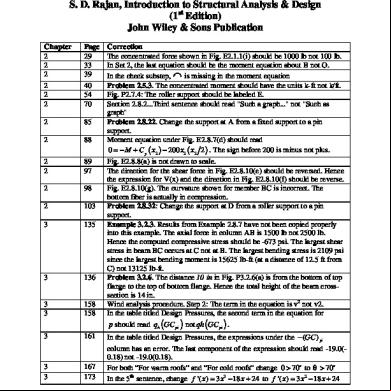
S. D. Rajan, Introduction to Structural Analysis & Design (1st Edition) John Wiley & Sons Publication Chapter 2 2 2 2 2 2
Page 29 33 39 40 54 70
2
85
2
88
2 2
89 97
2
98
2
103
3
135
3
136
3 3
158 158
3
161
3 3
167 173
© S. D. Rajan
Correction The concentrated force shown in Fig. E2.1.1(i) should be 1000 lb not 100 lb. In Set 2, the last equation should be the moment equation about B not O. In the check substep, [ is missing in the moment equation Problem 2.5.3. The concentrated moment should have the units k-ft not k/ft. Fig. P2.7.4: The roller should be labeled E. Section 2.8.2...Third sentence should read "Such a graph..." not "Such as graph" Problem 2.8.22. Change the at A from a fixed to a pin . Moment equation under Fig. E2.8.7(d) should read 0 = − M + C y ( x2 ) − 200 x2 ( x2 2 ) . The sign before 200 is minus not plus. Fig. E2.8.8(a) is not drawn to scale. The direction for the shear force in Fig. E2.8.10(e) should be reversed. Hence the expression for V(x) and the direction in Fig. E2.8.10(f) should be reverse. Fig. E2.8.10(g). The curvature shown for member BC is incorrect. The bottom fiber is actually in compression. Problem 2.8.32: Change the at D from a roller to a pin . Example 3.2.3. Results from Example 2.8.7 have not been copied properly into this example. The axial force in column AB is 1500 lb not 2500 lb. Hence the computed compressive stress should be -673 psi. The largest shear stress in beam BC occurs at C not at B. The largest bending stress is 2109 psi since the largest bending moment is 15625 lb-ft (at a distance of 12.5 ft from C) not 13125 lb-ft. Problem 3.2.6. The distance 10 in in Fig. P3.2.6(a) is from the bottom of top flange to the top of bottom flange. Hence the total height of the beam crosssection is 14 in. Wind analysis procedure. Step 2: The term in the equation is v2 not v2. In the table titled Design Pressures, the second term in the equation for p should read qh (GC pi ) not qh (GC pi ) . In the table titled Design Pressures, the expressions under the − (GC ) pi column has an error. The last component of the expression should read -19.0(0.18) not -19.0(0.18). For both “For warm roofs” and “For cold roofs” change 0 > 70o to θ > 70o In the 5th sentence, change f '( x ) = 3 x3 − 18 x + 24 to f '( x ) = 3 x 2 − 18 x + 24
1
S. D. Rajan, Introduction to Structural Analysis & Design (1 st Edition)
3
181
3
182
3wL2 3wL2 to σ = . max 4b 2 4b 3 2 sentence above Fig. E3.7.3(b), change V = 200,169 in 3 to V = 20,169 in 3 .
3
182
Last sentence, change b = 1008.45 4h 2 to b = 1008.45 4b2 .
3 3
183 186
2 sentence above Observation, change V = 20,088 in 3 to V = 20,169 in 3 .
4
192
4
226
4
230
4 4
231 234
4
234
4
237
4
240
5
255
5 5
261 266
Equation (E3.7.3a) change σ max =
P P not ri = . 10.56π 15.36π Second paragraph, last sentence. Delete the first occurrence of the word "used". Third paragraph starting with "The computation ...". "The virtual unit load is applied at A." should read "The virtual unit load is applied at C." In Fig. E4.5.2(b), the vertical reaction at A is shown to indicate that in a later step its value will be used. The correct direction for the reaction in the SVL is downwards not upwards. For segment AB, in FBD(SVL), the reaction at A should be 0.1 not 0.5. External Loads. "Let us assume that is ..." should read "Let us assume that it is..." External Loads. "...let the force in a typical member by N." should read "...let the force in a typical member be N." Example 4.5.5. Step 1. "is the fabrication ..." should read "is the fabrication error...". Step 2. "On can imagine ..." should read "One can imagine..." Problem 4.5.14. The problem statement should read I BC = 2 I AB = 2 I not
Eqn. (E3.7.4b) should read ri =
I BC = I AB = 2 I . Step 2. In the table, the FBD for segment DB has an error. The reaction at A labeled 130 should act upwards not downwards. Problem 5.1.5. The roller should be labeled B not A. In the equation for ( ∆ D ) x the moment expression in the first term should read x2 − x not − . In the next line, ∆ C should actually be ( ∆D ) x . 2 Step 4. Equation should be moments about C not A. Fig. E5.1.7(e). Bending moment at B should be 38.5 not 31.5. Second paragraph, Second sentence: Instead of "We now examine..." read "We now examine such a truss (simplified with t E removed) in greater detail." In Fig. 5.1.3.2(b), remove the vertical concentrated force acting at A. Problem 5.1.21. The load should be 10 kN not 10 k. Problem 5.1.26: The truss t symbols are missing at ts B and J. In Fig. 5.1.4.6(b), remove the horizontal concentrated force acting at A. x x The second term in the expression for α ABµ should be − 1 not 1 . 6 6 2
5 5 5
266 267 271
5 5 5 5 5
271 277 279 283 286
© S. D. Rajan
2
S. D. Rajan, Introduction to Structural Analysis & Design (1 st Edition)
5
290
5 5
300 314
5
323
Step 4. Second Equation. The term multiplying MA should be (9/4EI) not (9/EI). The limits of the integral for θ B are from b to L and not from 0 to L. General Procedure. Step 3. The figure number should be 5.2.1.1 not 5.2.11. In FBD IV, the direction of VB1 should be down not up. µ since this The label B in FBD of member BC (top of page) should read B
327
force changes between the FBD for AB and FBD for BC. At the bottom of the page: "From the FBD of beam BD, we have" should be
x
x
5
`
followed by ∑ M B = 0 not 5
328
5
331
5
332
5
333
6
337
6
338
6
344
6 6
346 353
6 6 6 6 6
356 360 360 368 370 and 371
6
374 and 375
6
377
© S. D. Rajan
∑M
D
= 0.
Problem 5.2.3. Without a roller at B, the problem is exactly the same as Problem 5.6. Introduce a roller at B. Problem 5.2.14. Write the two Slope-Deflection equations for M AB and M BA as usual…. simplify the equation for M AB . Problem 5.3. The at D should be a roller capable of moving horizontally. Problem 5.6. Dimensions are missing. Take the dimensions to be the same as those used in Problem 5.2.3, i.e. each span is 5 m. Eqn. (6.1.1.1) should have Am ×n not Am × x . In the definition of the upper triangular matrix, change i < j to i > j. In the definition of the lower triangular matrix, change i > j to i < j. Fig. 6.2.1.4. The displacements (degrees-of-freedom) should be labeled D1, D2 and D 3. Problem 6.2.1. The applied load should be 20 lb not 20 lb/in. In the line to the right of the word SOLUTION, change "see page 362" to "see page 350". Step 4: D3 should be -4.44367e-3 not 4.44367e-3. Problem 6.2.2: The truss t symbol is missing at t 1. Problem 6.2.3: The truss t symbol is missing at t 4. The label in Fig. 6.2.3.9(a) should be w not W. Element 1 Stiffness: The signs of the entries in locations (2,6), (6,2), (5,6) and (6,5) need to be reversed. Element 2 Stiffness: The signs of the entries in locations (2,6), (6,2), (5,6) and (6,5) need to be reversed. Element 1 Stiffness: The signs of the entries in locations (2,6), (6,2), (5,6) and (6,5) need to be reversed. Element 3 Stiffness: The signs of the entries in locations (2,6), (6,2), (5,6) and (6,5) need to be reversed. Renumber all the problems in this Exercise by decreasing the problem number by one - the problems are from 6.2.13 through 6.2.20 NOT 6.2.14 through 6.2.21.
3
S. D. Rajan, Introduction to Structural Analysis & Design (1 st Edition)
6
381
6
397
6
399
Example 6.3.1. The left side of the second equation in the solution should read U not U 0 . EA Eqn. (6.4.2.16). The entry at row 1, column 4 should be − not 0. L Example 6.4.3. The element load for element 1 should read q6' ×1 = {0 −15000 −25000 0 −15000 25000}
6
419
6
424
7
446
7
447
8
505
Eqn. (6.5.2.2) The second term in the parenthesis should read +cjDj not -cjDj. The same correction should be made to the expression shown on the first line following Fig. 6.5.2.1. The 87 k reaction at the second node in Fig. E6.5.4(c) should be acting downwards not upwards. The 411.4 k-ft moment reaction should be counterclockwise not clockwise. Member cross-sectional properties: Delete the contents within the parenthesis "(the rough .... 6 mm)". and change the Area to 0.8 m2 and the Moment of inertia to 0.7 m4. Make the corrections as a result of this on the output shown on page 448. Element Data Table. There is NO element 2. Delete the second row in the table. Example 8.3.1. Make the following corrections. ∂L 1 = 0 = 4 + 4 λ1 x1 ⇒ x1 = − . ∂x1 λ1 3 2 1 λ1 = : x1* = − ; x2* = ; f (x * ) = −3 2 3 3
3 2 1 λ1 = − : x1* = ; x2* = − ; f (x * ) = 3. 2 3 3 The final solution is as follows: x1* = − 2 3, x*2 = 1 3, f ( x* ) = −3 . 8
512
8 8
515 522
8
529
8 8 8 Answers to Selected Problems
535 557 563 643
© S. D. Rajan
Table on top of page. The Decimal value associated with Binary 001 should be 2.28571 not 2.25571. Third line. "... point in chosen." should read "... point is chosen." The solution presented is incorrect. Change the upper bounds to 50 (instead of 20). The final result is h=36.5 cm and f(x) = 7327 cm3. Fig. 8.7.1. The truss on the top right is incorrect. Its (member arrangement) should be exactly the same as the truss on the top left. Fig. 8.7.4.1: Label the element between C and E as 9 not 7. The material should be 0.2% HR steel. Problem 8.8.5 and Problem 8.8.6. The material should be 0.2% HR steel. Problem 1.1(c). The answer should be 1.1229(10-6 )slug/in 3 not the value of a force.
4
S. D. Rajan, Introduction to Structural Analysis & Design (1 st Edition)
644 645 645 645 649 650 651 654 654 664 and 665 679 Appendix E Inside back Cover
679
Inside Front Cover First Page
Inside Front Cover
Problem 2.7.8. Change F HC=F FC=2250.6 lb(T) to FHG=F FG=2250.6 lb(T) Problem 2.8.18. Change the shear force at B from -7.72 to -7.22. Problem 2.8.21. The curvatures shown in the moment diagram should be opposite of what are shown in the figure. Problem 4.3.7. Both the rotations are clockwise. Problem 3.6. The required inner radius is 0.71 in with a wall thickness of 0.11 in. Problem 5.1.16. The reaction labeled C y should actually be Dy . Problem 5.2.12: MCD should be -136.3 k-ft. The solution labeled 6.2.18 should actually read 6.2.19. The solution labeled 6.2.19 should actually read 6.2.20. The unit for Area is in2 not in3.
In section d. the second derivative of the cubic function should read f "( x ) = 6ax + 2b not f "( x ) = 6ax 2 + 2b . The line types (light solid and dashed lines) for the first and the second graphs are switched. The formula for the fixed-end moments for a concentrated load should read Pa 2b FEM BA = 2 . The figure has the right expression. L Area of the pipe should read A = π t ( t + 2 r ) . Make the same correction in Appendix B. The rotation at B on the cantilever beam with the UDL should read θ B =
wL2 not θ B = . 3EI The formulae for the moment of inertia of the rectangular hollow tube section only for the outer rectangle. The contribution from the inner rectangle needs to be subtracted. Make the same correction in Appendix B.
1 3 b + 2t )( h + 2w ) − bh 3 ( 12
Sx =
1 3 (h + 2w )( b + 2t ) − hb3 12
Sy =
Ix = Iy =
© S. D. Rajan
wL3 3EI
Ix 0.5h + w Iy 0.5h + t
5
Errata Sheet for
S. D. Rajan, Introduction to Structural Analysis & Design (1st Edition) John Wiley & Sons Publication Chapter 2 2 2 2 2 2
Page 29 33 39 40 54 70
2
85
2
88
2 2
89 97
2
98
2
103
3
135
3
136
3 3
158 158
3
161
3 3
167 173
© S. D. Rajan
Correction The concentrated force shown in Fig. E2.1.1(i) should be 1000 lb not 100 lb. In Set 2, the last equation should be the moment equation about B not O. In the check substep, [ is missing in the moment equation Problem 2.5.3. The concentrated moment should have the units k-ft not k/ft. Fig. P2.7.4: The roller should be labeled E. Section 2.8.2...Third sentence should read "Such a graph..." not "Such as graph" Problem 2.8.22. Change the at A from a fixed to a pin . Moment equation under Fig. E2.8.7(d) should read 0 = − M + C y ( x2 ) − 200 x2 ( x2 2 ) . The sign before 200 is minus not plus. Fig. E2.8.8(a) is not drawn to scale. The direction for the shear force in Fig. E2.8.10(e) should be reversed. Hence the expression for V(x) and the direction in Fig. E2.8.10(f) should be reverse. Fig. E2.8.10(g). The curvature shown for member BC is incorrect. The bottom fiber is actually in compression. Problem 2.8.32: Change the at D from a roller to a pin . Example 3.2.3. Results from Example 2.8.7 have not been copied properly into this example. The axial force in column AB is 1500 lb not 2500 lb. Hence the computed compressive stress should be -673 psi. The largest shear stress in beam BC occurs at C not at B. The largest bending stress is 2109 psi since the largest bending moment is 15625 lb-ft (at a distance of 12.5 ft from C) not 13125 lb-ft. Problem 3.2.6. The distance 10 in in Fig. P3.2.6(a) is from the bottom of top flange to the top of bottom flange. Hence the total height of the beam crosssection is 14 in. Wind analysis procedure. Step 2: The term in the equation is v2 not v2. In the table titled Design Pressures, the second term in the equation for p should read qh (GC pi ) not qh (GC pi ) . In the table titled Design Pressures, the expressions under the − (GC ) pi column has an error. The last component of the expression should read -19.0(0.18) not -19.0(0.18). For both “For warm roofs” and “For cold roofs” change 0 > 70o to θ > 70o In the 5th sentence, change f '( x ) = 3 x3 − 18 x + 24 to f '( x ) = 3 x 2 − 18 x + 24
1
S. D. Rajan, Introduction to Structural Analysis & Design (1 st Edition)
3
181
3
182
3wL2 3wL2 to σ = . max 4b 2 4b 3 2 sentence above Fig. E3.7.3(b), change V = 200,169 in 3 to V = 20,169 in 3 .
3
182
Last sentence, change b = 1008.45 4h 2 to b = 1008.45 4b2 .
3 3
183 186
2 sentence above Observation, change V = 20,088 in 3 to V = 20,169 in 3 .
4
192
4
226
4
230
4 4
231 234
4
234
4
237
4
240
5
255
5 5
261 266
Equation (E3.7.3a) change σ max =
P P not ri = . 10.56π 15.36π Second paragraph, last sentence. Delete the first occurrence of the word "used". Third paragraph starting with "The computation ...". "The virtual unit load is applied at A." should read "The virtual unit load is applied at C." In Fig. E4.5.2(b), the vertical reaction at A is shown to indicate that in a later step its value will be used. The correct direction for the reaction in the SVL is downwards not upwards. For segment AB, in FBD(SVL), the reaction at A should be 0.1 not 0.5. External Loads. "Let us assume that is ..." should read "Let us assume that it is..." External Loads. "...let the force in a typical member by N." should read "...let the force in a typical member be N." Example 4.5.5. Step 1. "is the fabrication ..." should read "is the fabrication error...". Step 2. "On can imagine ..." should read "One can imagine..." Problem 4.5.14. The problem statement should read I BC = 2 I AB = 2 I not
Eqn. (E3.7.4b) should read ri =
I BC = I AB = 2 I . Step 2. In the table, the FBD for segment DB has an error. The reaction at A labeled 130 should act upwards not downwards. Problem 5.1.5. The roller should be labeled B not A. In the equation for ( ∆ D ) x the moment expression in the first term should read x2 − x not − . In the next line, ∆ C should actually be ( ∆D ) x . 2 Step 4. Equation should be moments about C not A. Fig. E5.1.7(e). Bending moment at B should be 38.5 not 31.5. Second paragraph, Second sentence: Instead of "We now examine..." read "We now examine such a truss (simplified with t E removed) in greater detail." In Fig. 5.1.3.2(b), remove the vertical concentrated force acting at A. Problem 5.1.21. The load should be 10 kN not 10 k. Problem 5.1.26: The truss t symbols are missing at ts B and J. In Fig. 5.1.4.6(b), remove the horizontal concentrated force acting at A. x x The second term in the expression for α ABµ should be − 1 not 1 . 6 6 2
5 5 5
266 267 271
5 5 5 5 5
271 277 279 283 286
© S. D. Rajan
2
S. D. Rajan, Introduction to Structural Analysis & Design (1 st Edition)
5
290
5 5
300 314
5
323
Step 4. Second Equation. The term multiplying MA should be (9/4EI) not (9/EI). The limits of the integral for θ B are from b to L and not from 0 to L. General Procedure. Step 3. The figure number should be 5.2.1.1 not 5.2.11. In FBD IV, the direction of VB1 should be down not up. µ since this The label B in FBD of member BC (top of page) should read B
327
force changes between the FBD for AB and FBD for BC. At the bottom of the page: "From the FBD of beam BD, we have" should be
x
x
5
`
followed by ∑ M B = 0 not 5
328
5
331
5
332
5
333
6
337
6
338
6
344
6 6
346 353
6 6 6 6 6
356 360 360 368 370 and 371
6
374 and 375
6
377
© S. D. Rajan
∑M
D
= 0.
Problem 5.2.3. Without a roller at B, the problem is exactly the same as Problem 5.6. Introduce a roller at B. Problem 5.2.14. Write the two Slope-Deflection equations for M AB and M BA as usual…. simplify the equation for M AB . Problem 5.3. The at D should be a roller capable of moving horizontally. Problem 5.6. Dimensions are missing. Take the dimensions to be the same as those used in Problem 5.2.3, i.e. each span is 5 m. Eqn. (6.1.1.1) should have Am ×n not Am × x . In the definition of the upper triangular matrix, change i < j to i > j. In the definition of the lower triangular matrix, change i > j to i < j. Fig. 6.2.1.4. The displacements (degrees-of-freedom) should be labeled D1, D2 and D 3. Problem 6.2.1. The applied load should be 20 lb not 20 lb/in. In the line to the right of the word SOLUTION, change "see page 362" to "see page 350". Step 4: D3 should be -4.44367e-3 not 4.44367e-3. Problem 6.2.2: The truss t symbol is missing at t 1. Problem 6.2.3: The truss t symbol is missing at t 4. The label in Fig. 6.2.3.9(a) should be w not W. Element 1 Stiffness: The signs of the entries in locations (2,6), (6,2), (5,6) and (6,5) need to be reversed. Element 2 Stiffness: The signs of the entries in locations (2,6), (6,2), (5,6) and (6,5) need to be reversed. Element 1 Stiffness: The signs of the entries in locations (2,6), (6,2), (5,6) and (6,5) need to be reversed. Element 3 Stiffness: The signs of the entries in locations (2,6), (6,2), (5,6) and (6,5) need to be reversed. Renumber all the problems in this Exercise by decreasing the problem number by one - the problems are from 6.2.13 through 6.2.20 NOT 6.2.14 through 6.2.21.
3
S. D. Rajan, Introduction to Structural Analysis & Design (1 st Edition)
6
381
6
397
6
399
Example 6.3.1. The left side of the second equation in the solution should read U not U 0 . EA Eqn. (6.4.2.16). The entry at row 1, column 4 should be − not 0. L Example 6.4.3. The element load for element 1 should read q6' ×1 = {0 −15000 −25000 0 −15000 25000}
6
419
6
424
7
446
7
447
8
505
Eqn. (6.5.2.2) The second term in the parenthesis should read +cjDj not -cjDj. The same correction should be made to the expression shown on the first line following Fig. 6.5.2.1. The 87 k reaction at the second node in Fig. E6.5.4(c) should be acting downwards not upwards. The 411.4 k-ft moment reaction should be counterclockwise not clockwise. Member cross-sectional properties: Delete the contents within the parenthesis "(the rough .... 6 mm)". and change the Area to 0.8 m2 and the Moment of inertia to 0.7 m4. Make the corrections as a result of this on the output shown on page 448. Element Data Table. There is NO element 2. Delete the second row in the table. Example 8.3.1. Make the following corrections. ∂L 1 = 0 = 4 + 4 λ1 x1 ⇒ x1 = − . ∂x1 λ1 3 2 1 λ1 = : x1* = − ; x2* = ; f (x * ) = −3 2 3 3
3 2 1 λ1 = − : x1* = ; x2* = − ; f (x * ) = 3. 2 3 3 The final solution is as follows: x1* = − 2 3, x*2 = 1 3, f ( x* ) = −3 . 8
512
8 8
515 522
8
529
8 8 8 Answers to Selected Problems
535 557 563 643
© S. D. Rajan
Table on top of page. The Decimal value associated with Binary 001 should be 2.28571 not 2.25571. Third line. "... point in chosen." should read "... point is chosen." The solution presented is incorrect. Change the upper bounds to 50 (instead of 20). The final result is h=36.5 cm and f(x) = 7327 cm3. Fig. 8.7.1. The truss on the top right is incorrect. Its (member arrangement) should be exactly the same as the truss on the top left. Fig. 8.7.4.1: Label the element between C and E as 9 not 7. The material should be 0.2% HR steel. Problem 8.8.5 and Problem 8.8.6. The material should be 0.2% HR steel. Problem 1.1(c). The answer should be 1.1229(10-6 )slug/in 3 not the value of a force.
4
S. D. Rajan, Introduction to Structural Analysis & Design (1 st Edition)
644 645 645 645 649 650 651 654 654 664 and 665 679 Appendix E Inside back Cover
679
Inside Front Cover First Page
Inside Front Cover
Problem 2.7.8. Change F HC=F FC=2250.6 lb(T) to FHG=F FG=2250.6 lb(T) Problem 2.8.18. Change the shear force at B from -7.72 to -7.22. Problem 2.8.21. The curvatures shown in the moment diagram should be opposite of what are shown in the figure. Problem 4.3.7. Both the rotations are clockwise. Problem 3.6. The required inner radius is 0.71 in with a wall thickness of 0.11 in. Problem 5.1.16. The reaction labeled C y should actually be Dy . Problem 5.2.12: MCD should be -136.3 k-ft. The solution labeled 6.2.18 should actually read 6.2.19. The solution labeled 6.2.19 should actually read 6.2.20. The unit for Area is in2 not in3.
In section d. the second derivative of the cubic function should read f "( x ) = 6ax + 2b not f "( x ) = 6ax 2 + 2b . The line types (light solid and dashed lines) for the first and the second graphs are switched. The formula for the fixed-end moments for a concentrated load should read Pa 2b FEM BA = 2 . The figure has the right expression. L Area of the pipe should read A = π t ( t + 2 r ) . Make the same correction in Appendix B. The rotation at B on the cantilever beam with the UDL should read θ B =
wL2 not θ B = . 3EI The formulae for the moment of inertia of the rectangular hollow tube section only for the outer rectangle. The contribution from the inner rectangle needs to be subtracted. Make the same correction in Appendix B.
1 3 b + 2t )( h + 2w ) − bh 3 ( 12
Sx =
1 3 (h + 2w )( b + 2t ) − hb3 12
Sy =
Ix = Iy =
© S. D. Rajan
wL3 3EI
Ix 0.5h + w Iy 0.5h + t
5
Related Documents 3m3m1z
December 2019 64
Structural Analysis And Design Lectures 5t173y
February 2021 0
Staircases Structural Analysis And Design 5jz5
October 2019 88
December 2019 76

October 2019 67

October 2019 52