Ksb Pump Multitec Spec 305z3v
This document was ed by and they confirmed that they have the permission to share it. If you are author or own the copyright of this book, please report to us by using this report form. Report 3b7i
Overview 3e4r5l
& View Ksb Pump Multitec Spec as PDF for free.
More details w3441
- Words: 3,097
- Pages: 8
File Name: KSB_Pump_Multitec_spec_D1003 Product Introduction 1777.1/4-10 G3
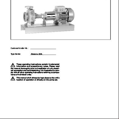
Multitec High-Pressure Pumps in Ring-Section Design
Applications
Bearings/Lubrication
General water supply Pressure boosting Municipal water supply Drinking water supply Irrigation Heating Boiler feed water Warm water Hot water Circulation Condensate
Distillate Industry Filter systems Solvents Fire-fighting systems Washing systems Reverse osmosis Lubricants Fuels Process Power plants
Operating data Pump sizes Capacities Heads Operating temperature Operating pressures Standard flanges Suction nozzle Discharge nozzle Standard flanges Suction nozzle Discharge nozzle
DN 32 up to 150 Q up to 850 m3/h, 236 l/s H up to 630 m t --10 _C up to +200 _C p2 25 up to 63 bar 1) DIN PN 16 (JL1040) and PN 25 (GP240GH+N, 1.4408) PN 40 (JL1040) and PN 63 (GP240GH+N, 1.4408) ASME Class 125 (JL1040) and Class 300 (GP240GH+N, 1.4408) Class 250 (JL1040) and Class 600 (GP240GH+N, 1.4408)
1) The total of inlet pressure and head at zero flow must not exceed the specified value
Design Horizontal or vertical multistage centrifugal pump in ring section design, as long-coupled (baseplate mounted) or close-coupled unit. Axial or radial suction nozzle. Radial suction and discharge nozzle can be turned in multiples of 90. Flanges to EN, DIN and ANSI (bolt holes, flange face) Closed radial impellers, from pump size 50 upwards first stage with suction impeller to improve the NPSH value.
DIN EN ISO 9001 General Member of
Drive side: rolling element bearings Suction side: plain or rolling element bearings, depending on installation type Lubrication: Rolling element bearings grease lubricated, oil lubrication possible Plain bearings are product lubricated.
Shaft seal Standardized mechanical seal, uncooled or cooled, single-acting or double-acting. Cartridge seals possible. Uncooled gland packing with or without barrier liquid.
Designation Multitec A 32 / 8E - 2.1 12 . 65 (SP) Pump series Installation type DN discharge nozzle Number of stages/Impeller combination Hydraulics Material variant Shaft seal code Code for special variants (optional)
Materials Cast iron JL1040, Hydraulic elements: bronze CC480K-GS (water works variant), cast steel GP240GH+N, alloyed cast steel 1.4408
Drive Electric motor 50 and 60 Hz; Diesel engine or turbine up to nmax. 4000 1/min possible
Certification Certification of quality management ISO 9001
Multitec Kennfelder / Selection charts / Réseau / Conjunto de curvas / Campi caratteristici / Grafieken / Arbetsområde n = 2900 1/min (1.4408) 10 US.gpm
20
30
10
700
20
40 30
50 40
100 50
200
IM.gpm 100
300 200
400 500 300
1000
400 500
2000
1000
3000 4000
2000
3000 2000
500 125 9.1 125 10.1
400
150 11.1 150 12.1
65 6.1
1000
100 8.1
300 50 3.1
50 4.1
65 5.1
150 11.2
100 7.1
150 12.2
125 9.2
200 125 10.2
500 400
32 2.1
100 300 H [m] 200 50 ft 40 100
30 25 2
3
4 1
3
5
Q[m /h] 10
l/s
2
20
3
4
30
5
40
50
100
10
20
200
30
40
300
50
400 500 100
1000
200 KE1777.ES.S.452/1
n = 3500 1/min (1.4408) 20 10 IM.gpm
700
30 20
40 30
50 US.gpm 100 40
50
200 100
300 200
400 500 300
1000
400 500
2000
1000
3000 4000
2000
3000 4000 2000
500 400 100 8.1
65 6.1
125 9.1 125 10.1
300 65 5.1
50 4.1
1000
150 11.2
100 7.1
150 12.2
50 3.1 125 9.2 125 10.2
200
32 2.1
500 400 100 300 ft
H [m]
200 50 40 35 2.5 3
4 1
2
5 l/s
3
Q[m /h] 10 2
3
20 4
5
30
40 10
50
100 20
30
200 40
50
300
400 500 100
1000
1400
200 300 KE1777.ES.S.462/1
Multitec Selection of material/shaft seal depending on the pumped liquid Pumped liquid
Material p2 max ≤140 C ≤200 C
Shaft seal Notes ≤100 C ≤140 C ≤200 C
in bar Sewage, raw water 1)
40
10
slightly contaminated water
63
20
Drinking water 1)
40
11,12
63
22
40 40
11,12 10
63
20
Boiler feed water 2)
40
10
20
p g mode AF,, pH p > 9 (objective ( j Operating
63
20
20
≥ 9.3) at 25 C
40
22
22
63
22
22
Boiler feed water 2)
40
10
20
p g mode AFT,, pH p > 9 (objective ( j Operating
63
20
20
≥ 9.3) at 25C
40
22
22
63
22
22
Boiler feed water 2)
40
30
30
Operating mode NF. pH ≥ 6.5 at 25 C
63
30
30
Boiler feed water 2)
40
22
22
Operating mode KF. pH ≥ 8 - 8.5 at 25 C
63
22
22
Condensate 2)
40
10
20
Operating mode AF, pH > 9 (objective
63
20
20
≥ 9.3) at 25 C Condensate 2)
40
30
30
Operating mode NF, pH ≥ 6.5 at 25 C
63
30
30
Condensate 2)
40
22
Operating mode KF, pH ≥ 8 at 25 C
63
22
Raw water for reverse osmosis plants
40
30
30
63
30
30
Fire-fighting water 1) Cooling water
63, 65
Non-aggressive pumped liquid, no abrasive components
65,615),63
Water works variant
65,615),62 65,615),62
Non-aggressive pumped liquid, no abrasive components
65,615),62
66, 62
64
65,615),62
62
64
65,615),62
66, 62
64
65,615),62
66, 62
64
615),62
62
64
O2 content ≥ 0.05 mg/kg
65,615),62
66, 62
64
O2 content 0.15 up to 0.3 mg/kg
615),62
62
64
O2 content ≤ 0.02 mg/kg
O2 content ≤ 0.02 mg/kg
O2 content ≤ 0.02 mg/kg temperature ≤ 190 C 4)
615),62
62
64
65,615),62
66, 62
64
O2 content ≥ 0.15 mg/kg temperature ≤ 110 C 4)
615),62
62
64
For higher chloride content (sea water) KSB In case of prolonged shutdown, drain and flush the pump
Oil-water mixture,
40
10
oil emulsion
63
20
Glycol-water mixtures
40
10
63
20
Degreasing baths, washing solution for
40
10
metal cleansing,
63
20
65, 63 65,615),62 65, 63
66, 62 3) e.g. P -lye 3
for acid baths please KSB
alkaline cleaning agents 1) General assessment criteria when a water analysis is available: pH value ≧ 6.5; chloride content (Cl’) ≦ 150 mg/kg, chlorine (Cl2) ≦ 0.6 mg/kg. For bronze components, the following additional limits apply: ammonia (NH3) ≦ 5 mg/kg, free of hydrogen sulphide (H2S); the limitation of the Cl’ content does not have to be applied in this case. If these limits are not complied with, please KSB. 2) The values must be assured upstream of the pump inlet under all operating conditions. Water treatment shall comply with the VdTÜV regulations for feed and boiler water grades for steam plants up to 64 bar. Air ingress into the system must be avoided by all means. We therefore recommend to use a mechanical seal as a shaft seal. Notes for the suction pipe layout: Max. flow velocity approx. 1.5 m/s, low pressure loss arrangement (few pipe fittings/ valves, low drag valves, e.g. gate valves instead of globe valves, pipe arrangement short and vertical, horizontal sections should be located at the deepest position). Using impellers made of G-CuSn10 is only possible when no additives containing ammonia (e.g. Hydrazin) are used for water treatment.
AF
=
Water is fully demineralised, pH value set to > 9 (e.g. using ammonia).
AFT =
Water is partly demineralised, pH value set to ∫ 9, mainly with solid alkalising agents, possibly additional dosing of ammonia.
NF
=
Water is fully demineralised, pH value ∫ 7-8, O2 content increased to 0.05-0.25 mg/kg by adding oxygen or hydrogen peroxide.
KF
=
Water is fully demineralised, alkalised to pH values from 8 to 9, O2 content increased to 0.03-0.15 mg/kg by adding oxygen or hydrogen peroxide.
3) max. 80 C; pH value > 9.5 4) Values drawn from experience 5) See application limits on page 6
3
Multitec Operating ranges depending on installation type 640
Installation type A, B, C, D 400
H m
Installation type A, B, C, D, V
Installation type A, B, C, D
250
Installation type A, B, C, D, E, Ex, F, Fx, V, Vx
Installation type A, B, C, D, V
DN 65
DN 125
Heads given for n = 2900 1/min and n = 3500 1/min 4
Installation type A, B, C, D DN 150
Multitec Technical Description Installation type
Installation type A
Installation type B
Technical description 5)
5)
Horizontal design, baseplate mounted, rolling element bearings on drive side, side plain bearings on suction side, one shaft seal only, y, axial i l suction ti nozzle l (block flange up to pump size 50), drive on discharge side
Drive
Electric motor, Diesel engine, turbine
Axial thrust balance
By balance drum 1)
Qmax 2)
840 m3/h
Hmax
630 m
For the entire Q/H range
p2 max
63 bar
Same as installation type A, but with radial suction nozzle
tmax
-10 up to +200 C
Shaft seal
Uncooled packing; cooled or uncooled mechanical seal single or double-acting Cartridge seals Grey cast iron JL1040, bronze CC480K-GS, cast steel 1.0619+N, 1.4408
Material
Installation type C
Installation type D
5)
6)
Horizontal design, baseplate mounted, rolling element bearings on drive and suction side, shaft seals at both ends,, d i on discharge drive di h side id
Drive
Electric motor, Diesel engine, turbine
Axial thrust balance
By balance drum 1)
Qmax 2)
840 m3/h
For the entire Q/H range
Hmax
630 m
p2 max
63 bar
tmax
-10 up to +200 C
Shaft seal
Uncooled packing; cooled or uncooled mechanical seal single or double-acting Cartridge seals Grey cast iron JL1040, bronze CC480K-GS, cast steel 1.0619+N, 1.4408
Same as installation type C, but drive on suction side
Material
Installation type E, Ex 5)
Horizontal close coupled pump, common bearing for pump and motor, motor rigid coupling, radial suction nozzle up to DN 65
Installation type F, Fx
5)
Same as installation type E, Ex, but with axial suction nozzle
5)
Drive
Electric motor with special rolling element bearing
Standardized motor
Axial thrust balance
Held by motor bearing
By balance drum
Qmax 2)
100 m3/h
Hmax
250 m
p2 max
Q/H
25 bar
40 bar
-10 up to +140 C
Shaft seal
Uncooled packing; uncooled mechanical seal single-acting
Material
Grey cast iron JL1040, bronze CC480K-GS, other materials on request
2-pole: up to QOpt=180 m3/h, 250 m up to QOpt= 85 m3/h, / 400 m
Drive
Electric motor with special rolling element bearing
4-pole: up to QOpt= 175m3/h, 250 m
Axial thrust balance
Vertical close coupled pump range2):
E, F
tmax
up to t DN 65
Installation type V, Vx
Ex, Fx
1) For small number of stages without balance drum: axial thrust fully held by the axial bearings 2) N.B.: The values given for Q apply to 50 Hz; for 60 Hz values please refer to the specific performance curves.
3) 4) 5) 6)
Vx
V Standardized motor
Fixed bearing in lantern
Qmax 2) 4)
DN 100 DN 125 3) Held by motor bearing
By balance drum
100 m3/h
Hmax 4)
250 m
p2 max 4)
25 bar
170 m3/h 400 m
250 m
40 bar
tmax
-10 up to +140 C
Shaft seal
Uncooled packing; uncooled mechanical seal single-acting
Material
Grey cast iron JL1040, bronze CC480K-GS, other materials on request
DN 150 on request Other operating data on request Clockwise drive rotation when viewed from the motor end Anti-clockwise drive rotation when viewed from the motor end
5
Multitec Pressure and temperature limits Material JL1040 (GJL-250)
Material GP240GH+N (1.0619+N) ASME Class 600
60
60
EN 1092-1, PN 63 (DIN 2546, PN 63)
EN 1092-2, PN 40 (DIN 2535, PN 40) 40
40
p bar
ASME Class 250
p bar
20
EN 1092-2, PN 16 (DIN 2533, PN 16)
20
EN 1092-1, PN 25 (DIN 2544, PN 25)
ASME Class 300
ASME Class 125
0 --10
0
50
t C
100
140 150
200
0 --10
0
50
t C
100
150
Material 1.4408
60 ASME Class 600 EN 1092-1, PN 63 (DIN 2546, PN 63) 40 p bar
ASME Class 300
20 EN 1092-1, PN 25 (DIN 2544, PN 25)
0 --10
0
t C
50
Shaft seal code
100
150
200
2)
Mechanical seal Uncooled mechanical seal up to 100 C
Non-balanced bellows-type seal RMG 13 (U3BEGG) Balanced seal H12N (AQ1EGG) Balanced seal Solids-laden media H17GN (Q12Q1VGG) 6) Balanced seal H75N (AQ1EGG)
Cooled mechanical seal
up to 140 C
up to 200 C 3)
pump sizes 32 and 50 only
--
--
62 4)
62 4)
--
63 5)
--
--
--
--
64 4)
Temp. limits
61
1) 4)
Gland packing Pmax
without balance drum with balance drum
1) 2) 3) 4) 5) 6)
6
65 5)
66 4)
with suction head operation PS abs. ≥ 1 bar
Technical features
up to 140 C (ARAMID / SILIKON)
N/b
Design Plant conditions
up to 100 C (RAMIE / PTFE)
25 bar 63 bar
without lantern ring
N/c PS abs. < 1 bar (vacuum vessel)
with clean external sealing liquid barrier pressure > pressure to be sealed 1 lantern ring on suction side 1 lantern ring on discharge side 2 tapped holes for auxiliary pipework
pmax without balance drum = 18 bar; pmax with balance drum = 63 bar Other seal variants on request Air-cooled up to DN 100 (installation types A, B, C and D, electric motor IP 55, 2-pole, only); otherwise water-cooled. static seals in EPDM static seals in FPM H75N (Q1Q1VGG) for pump size 150
200
Multitec Materials table Part no. Description 106 107 108 171 210 230 231 350 381/529 441 502 7) 523 524 550.1 8) 59-4 540 905
Material code 10 3)
11 3)
12 3)
20
JL1040 JL1040 JL1040
JL1040 JL1040 JL1040
JL1040 JL1040 S355J2G3 1)/JL1040 2)
JL1040 2)6) C45+N 4) JL1040 JL1040 JL1040 SiC/SiC JL1040 JL1040 2) 1.4057+QT800 1.4122 1.4571 JL1040 JL1040 C45K (or 42 CrMo4)
JL1040 2)6) C45+N 4) CC480K-GS CC480K-GS JL1040 SiC/SiC JL1040 CC493K-GS 2) 1.4057+QT800 1.4122 1.4571 1.4021 JL1040 C45K (or 42 CrMo4)
CC480K-GS C45+N 4) CC480K-GS CC480K-GS JL1040 SiC/SiC JL1040 CC493K-GS 2) 1.4057+QT800 1.4122 1.4571 1.4021 JL1040 C45K (or 42 CrMo4)
GP240GH+N GP240GH+N S355J2G3 1)/ GP240GH+N 2) JL1040 C45+N 4) JL1040 JL1040 JL1040 SiC/SiC GP240GH+N JL1040 1.4057+QT800 1.4122 1.4571 JL1040 JL1040 1.6772 (Monix 3K)
21
22
23
30
GP240GH+N GP240GH+N S355J2G3 1)/ GP240GH+N 2) JL1040 C45+N 4) JL1040 1.4408 JL1040 SiC/SiC GP240GH+N JL1040 1.4057+QT800 1.4122 1.4571 JL1040 JL1040 1.6772 (Monix 3K)
GP240GH+N GP240GH+N S355J2G3 1)/ GP240GH+N 2) 1.4408 1.4021+QT 1.4408 1.4408 JL1040 SiC/SiC GP240GH+N 1.4138 1.4571 1.4122 1.4571 1.4021 1.4021 1.6772 (Monix 3K)
GP240GH+N 1.4408 S355J2G3 1)/ GP240GH+N 2) 1.4408 1.4021+QT 1.4408 1.4408 JL1040 SiC/SiC 1.4408 1.4138 1.4571 1.4122 1.4571 1.4021 1.4021 1.6772 (Monix 3K)
1.4408 1.4408 1.4404 1) 1.4408 2)
Suction casing Discharge casing Stage casing Diff Shaft Impeller Suction impeller Bearing housing Plain bearing assy. Stuffing box housing Casing wear ring Shaft sleeve Shaft protecting sleeve Disc Balance drum Bush Tie bolt
Part no. Description 106 107 108 171 210 230 231 350 381/529 441 502 7) 523 524 550.1 8) 59-4 540 905 1) 2) 3) 4) 5)
Suction casing Discharge casing Stage casing Diff Shaft Impeller Suction impeller Bearing housing Plain bearing assy. Stuffing box housing Casing wear ring Shaft sleeve Shaft protecting sleeve Disc Balance drum Bush Tie bolt
Material code
For pump sizes DN 32 up to 100 For pump sizes DN 125 and 150 Up to t ± 140 _C Available in material 1.4021 Only provided for seal codes 61, 62, 63, 64 (no packing)
1.4408 1.4462 1.4408 1.4408 JL1040 SiC/SiC 1.4408 5) 1.4571 1.4571 5) 1.4571 1.4301 1.4301 1.6772 (Monix 3K)
6) Integrated in stage casing of pumps sizes 32 to 100. 7) Pump sizes 125 and 150 only, and casing wear ring in suction casing for pump sizes 32 to 100 of material variants 20 to 30 8) For pump sizes 32 to 100 only, also used as casing wear ring
Material Equivalents Description Cast iron Cast bronze Cast bronze Steel Steel Steel Cast steel Chrome steel Chrome nickel steel Chrome nickel steel Chrome molybdenum cast steel Chrome nickel steel Chrome nickel molybdenum steel Chrome nickel molybdenum cast steel Chrome nickel molybdenum steel Chrome nickel molybdenum steel Silicon carbide Bar steel Steel
Short designation and material No. JL1040 / GJL-250 CC480K-GS CuSn7Zn4PB7-C-GS/CC493K-GS C45+N / 1.0503+N C45K / 1.0503 K S355J2G3 / 1.0570 GP240GH+N / 1.0619+N 1.4021+QT / X20Cr13+QT 1.4122 / X35CrMo17 1.4057+QT800 / X17CrNi16-2--QT800 1.4138 / GX120CrMo29-2 1.4301 / X5CrNi18-10 1.4404 / X2CrNiMo 17-12-2
Standard EN 1561 EN 1982 EN 1982 EN 10083-2 DIN 1652 EN 10025 EN 10213-2 EN 10088 EN 10088 EN 10088-3
to NF A ----AF65C45 E36-4 -----
to ASTM A48:40B B505C90250 B585C93200 (similar) A29Gr.1045 A663 A678C A216WCB A276:420 A276S42010 (similar) A276:431
SEW 410 EN 10088 EN 10088
Z1200D29-02-M ---
-A276:304 A276:316L
1.4408 / GX5CrNiMo19-11-2
EN 10213
--
A743CF8M
1.4462 / X2CrNiMoN22-5-3 1.4571 / X6CrNiMoTi17-12-2 SiC without free silicon 1.6772 / 20NiCrMo14-5 I 42CrMo4 / 1.7225
EN 10088 EN 10088 --
--Carbure de silicium sans silicium libre 16NC11n. A36-612 --
A473 S32950 A276:316 SiC without free silicon A540 Gr. B24 A322GR.4140 (similar)
VdTÜV 337 EN 10083-1
7
Multitec Benefits at a glance 1st stage with special suction impeller - low NPSH required - reliable for suction lift operation thanks to improved suction behaviour
Newly developed hydraulics - High efficiencies - Low operating costs
Wear rings made of 1.4571 Pump size 32 to 100: standard Pump size 125 to 150: depending on material variant - Highly resistant - Easily replaceable with low costs
Axial thrust balancing with balance drum - Low bearing loads under variable operating conditions - Low pressure in the shaft seal area - Long life of rolling element bearings and shaft seal
Plain bearings made of silicon carbide - Longer service life - Higher reliability - Low maintenance costs - One shaft seal only - Dimensioned for start-stop operation and all speeds
Shaft sealed by - Uncooled gland packing up to 140 C - Standardized mechanical seal, balanced or non-balanced Uncooled up to 140 C, cooled up to 200 C - Single or double-acting, cartridge seals
Shaft protecting sleeve made of alloyed steel - Efficient protection of the shaft from wear - Quick and simple replacement of the shaft seal
d/4
Adaptation of the material from many possible options (JL 1040, Bronze, GP240GH+N, 1.4408)
Subject to technical modifications.
between bearings design
1777:7
Double acting mechanical seal, e.g. tandem arrangement d/4
Mechanical seal, single-acting
01.03.2002
1777:5
Axial inlet pump size ² 65 Installation type V; Separate rolling element bearing in the motor lantern from pump size 100 upwards Installation type E
KSB S.A. Allée de Sagan - B. P. 189 . 36004 Châteauroux Cedex Tél.: (02) 54 08 84 00 Fax: (02) 54 08 84 91 http://www.ksb.com
Related Documents 3m3m1z

Ksb Pump Multitec Spec 305z3v
December 2019 122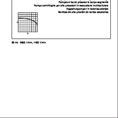
Ksb Multitec 563c4i
April 2023 0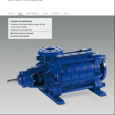
Manual De Bomba Ksb Multitec 464d6e
December 2019 136
Ksb Centrifugal Pump Design 2m1e5w
December 2019 148
Feed Pump Ksb 41e4e
December 2019 113