Liebherr R 996 B Oem Specs 334gj
This document was ed by and they confirmed that they have the permission to share it. If you are author or own the copyright of this book, please report to us by using this report form. Report 3b7i
Overview 3e4r5l
& View Liebherr R 996 B Oem Specs as PDF for free.
More details w3441
- Words: 3,206
- Pages: 14
Mining Excavator
R 996 B
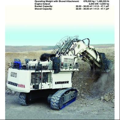
Operating Weight with Backhoe Attachment: 672,000 kg / 1,481,506 lb Operating Weight with Shovel Attachment: 676,000 kg / 1,490,325 lb Engine Output: 2,240 kW / 3,000 hp Bucket Capacity: 32.00 - 36.00 m³ / 41.9 - 47.1 yd³ Shovel Capacity: 32.00 - 36.00 m³ / 41.9 - 47.1 yd³
NTB_R996_BT_enGB.indd 1
01.04.10 19:04
R 996 B Operating Weight with Backhoe Attachment: 672,000 kg / 1,481,506 lb Operating Weight with Shovel Attachment: Engine Output:
2
676,000 kg / 1,490,325 lb 2,240 kW / 3,000 hp
Bucket Capacity:
32.00 - 36.00 m³ / 41.9 - 47.1 yd³
Shovel Capacity:
32.00 - 36.00 m³ / 41.9 - 47.1 yd³
R 996 B
NTB_R996_BT_enGB.indd 2
01.04.10 19:04
R 996 B
NTB_R996_BT_enGB.indd 3
3
01.04.10 19:04
New Backhoe Bucket Design • Capacity of 36 m³ / 47.1 @ 1.8 t/m³ or 3,000 lb/yd³ • Improved shape for wear reduction • Perfect match for trucks with 220 t payload and above • Integrated approach on machine capabilities, material properties and truck target payloads • Customized and site-specific wear package configuration
4
R 996 B
NTB_R996_BT_enGB.indd 4
01.04.10 19:04
Performance by Design Liebherr’s R 996 B provides more productivity at lower cost per tonne mined. The mining excavator remains more than ever the reliable basis in your production. Perfectly suitable for 220 t class trucks and above, the R 996 B sets new standards to your mining operation. High Productivity
Reach a New Level of Productivity: The R 996 B backhoe attachment has been redesigned to achieve larger bucket capacity. Even under tough conditions Liebherr’s R 996 B high digging force allows easy bucket penetration and high bucket fill factors achieving high productivity.
Reliability
Slew system and undercarriage further improve the machine reliability and extend the component lifetime. The enhanced single-line lubrication system and the fuel and oil filtration system also enhance availability of the mining excavator.
Operator Cab
The R 996 B’s spacious cab offers ideal working conditions and first-class comfort. The adjustable air suspension seat fits to individual needs. Best visibility over the whole working environment is provided by the enhanced position of the cab. The hanging arch hose arrangement provides direct visibility over large areas of the uppercarriage. Additionally, a camera system shows areas that can’t be observed directly. The electronic machine controls assure the best operator performance throughout each shift. Furthermore, the ergonomic component access and long service intervals assist the service team to ensure more uptime.
Safety and Environment
Railings and catwalks help to easily access all relevant machine areas. The 45° access stair helps entering the machine comfortably. In case of emergency stops the stair is automatically lowered. Liebherr also provides solutions for operations close to residential areas with machine specific sound attenuation packages. The approach is based on both removal of noise at the source and ive sound attenuation resulting in low machine noise emissions.
New Easy and Safe Machine Access
Finite Element Analysis (FEM)
• New 45° access system
• Multibody simulations
• Integrated in uppercarriage structure
• Fatigue calculations for longest possible lifetimes
• Full controlled descent in case of emergency stop • Strong design
R 996 B
NTB_R996_BT_enGB.indd 5
5
01.04.10 19:04
Technical Data Engine 2 Cummins diesel engines Rating per SAE J 1995 ���������������� 2 x 1,120 kW/2 x 1,500 hp at 1,800 rpm Model ������������������������ K 1800 E Type �������������������������� 16 cylinder V-engine, water-cooled, direct injection, turbo-charged, after-cooler Displacement ������������� 50.3 l/3,069 in3 Bore/Stroke ���������������� 159/159 mm / 6.26/6.26 in Air cleaner ����������������������� dry-type air cleaner with pre-cleaner, with automatic dust ejector, primary and safety elements Fuel tank ������������������������� 13,000 l/3,440 gal Electrical system Voltage ���������������������� 24 V Batteries �������������������� 8 x 170 Ah/12 V Alternator ������������������� 2 x 24 V/150 Amp Engine idling �������������������� sensor controlled
Hydraulic System Hydraulic pumps for attachment and travel drive ����������������� 8 variable flow axial piston pumps Max. flow ������������������� 8 x 840 l/min. / 8 x 222 gpm Max. hydr. pressure ���� 320 bar/4,640 psi Hydraulic pumps for swing drive ������������ 4 reversible swash plate pumps, closedloop circuit Max. flow ������������������� 4 x 413 l/min. / 4 x 10⁹ gpm Max. hydr. pressure ���� 350 bar/5,076 psi Pump management ���������� electronically controlled pressure and flow management with oil flow optimisation Hydraulic tank capacity ����� 4,600 l/1,215 gal Hydraulic system capacity �������������������������� 8,200 l/2,166 gal Hydraulic oil filter �������������� 1 high pressure safety filter after each high pressure pump + fine filtration of entire return flow Hydraulic oil cooler ����������� 2 separate coolers, 4 temperature controlled fans driven via hydraulic piston motors Electronic engine speed sensing ������������������ over the entire engine RPM range Lubrication ���������������������� central lubrication system
Hydraulic Controls Servo circuit �������������������� independant, electric over hydraulic proportional controls of each function Emergency control ������ via accumulator for all attachment functions with stopped engine Power distribution ������������ via monoblock control valves with inte grated primary relief valves and flanged on secondary valves for travel Flow summation ��������� to attachment and travel drive Control functions Attachment and swing ������������������������ proportional via joystick levers Travel ������������������������ proportional via foot pedals or hand levers Bottom dump bucket �� proportional via foot pedals Operation with one engine possible
6
Electric System Electric isolation ��������������� easy accessible battery isolations Working lights ������������������ Xenon lights: – 4 on working attachment – 2 on RHS (top of the fuel tank) – 2 on LHS (top of the hydraulic tank) – 2 on counterweight 6 additional Xenon lights: – 2 on the top of the cab – 2 on the RHS (bottom part of the fuel tank) – 2 on the LHS (bottom part of the hydraulic tank) Emergency stop switches �� at ground level, in hydraulic compartment, in engine compartment and in operator cab Electrical wiring ���������������� heavy duty execution in IP 65 standard for operating conditions of – 50 °C to 100 °C/ – 58 °F to 212 °F
Swing Drive Hydraulic motor ���������������� 4 Liebherr axial piston motors Swing gear ���������������������� 4 Liebherr planetary reduction gears Swing ring ����������������������� Liebherr, sealed triple roller swing ring, internal teeth Swing speed �������������������� 0 – 3.5 rpm Swing-holding brake ��������� hydraulically released, maintenance-free, multi-disc brakes integrated in each swing gear
Uppercarriage Design ���������������������������� torsion resistant designed upper frame in box type construction for superior strength and durability Attachment mounting ������� parallel longitudinal main girders in boxsection construction Machine access ��������������� 45° access system with handrails on the cab side of the uppercarriage. Full controlled descent in case of emergency stop. Additional emergency ladder fitted near the cab
Service Flap Design ����������������������������� hydraulically actuated service flap, easily accessible from ground level to allow: – fuel fast refill – hydraulic oil refill – engine oil quick change – splitterbox oil quick change – swing gearbox oil quick change – swing ring teeth grease barrel refilling via grease filter – attachment/swing ring bearing grease barrel refilling via grease filter – windshield washer water refilling Other coupler type on request
R 996 B
NTB_R996B_T_enGB-US_10-03.indd 6
01.04.10 10:49
Technical Data Operator’s Cab Design ���������������������������� resiliently mounted, sound insulated, large windows for all-around visibility, integrated falling object protection FOPS Operator’s seat ���������������� suspended, body-contoured with shock absorber, adjustable to operator’s weight Cabin windows ���������������� 20.5 mm/0.8 in tinted armored glass for front window and left hand side windows, all other windows in tinted safety glass, high pressure windshieldwasher-system with 75 l/20 gal watertank, sun louvers on all windows in heavy duty design Heating system/ Air conditioning ���������������� heavy duty, high output air conditioner and heater unit (electronic controlled) Cabin pressurization ��������� ventilation unit with filters Controls �������������������������� joystick levers integrated into armrest of seat Monitoring ����������������������� via LCD-Display, data memory Rear vision system ������������ camera installation on counterweight and left-hand side of the uppercarriage dis played over an additional LCD-display Automatic engine shut off ���������������������������� in case of low engine oil pressure or low coolant level Destroking of main pumps ��������������������� in case of engine overheating or low hydraulic oil level Safety functions ��������������� additional gauges with constant display for: engine speed, hourmeter, engine oil pressure, coolant temperature and hydraulic oil temperature Noise level (ISO 6396) ������� Lpa (inside cab) = 78 dB(A) with oil/water fans at 100 % and AC fan at 65 %
Central Lubrication System Type ������������������������������� Lincoln Centromatic lubrication system for the entire attachment/swing ring bearing and teeth Grease pumps ����������������� 1 Lincoln Powermaster pump for attachment/swing ring bearing lubrication (second pump with switch over function in option) 1 Lincoln Flowmaster pump for swing ring teeth lubrication Capacity �������������������������� 600 l/158.5 gal bulk container for attachment/swing ring bearing, separated 80 l/ 21 gal container for swing ring teeth Refill ������������������������������� via the service flap for both containers with grease filters
Attachment Design ���������������������������� box type structure with large steel castings in all high-stress areas Pivots ����������������������������� sealed with double side centering with 1 single floating pin per side, all bearings with wear resistant, steel bushings, bolts hardened and chromium-plated Hydraulic cylinders ����������� Liebherr design, all cylinders located in well protected areas Hydraulic connections ������ pipes and hoses equipped with SAE split flange connections Kinematics ���������������������� Liebherr parallel face shovel attachment geometry
Undercarriage Design ���������������������������� 3-piece undercarriage, box type structures for center piece and side frames, stress relieved Hydraulic motor ���������������� 2 axial piston motors per side frame Travel gear ����������������������� Liebherr reduction gear Travel speed �������������������� 0 – 2.2 km/h / 0 – 1.4 mph Parking brake ������������������� spring engaged, hydraulically released wet multi-disc brakes for each travel motor, maintenance-free Track components ������������ maintenance-free combined pad-link, heavy duty track shoes Track rollers/ Carrier rollers ������������������� 7/3 Automatic track tensioner ������������������������� pressurized hydraulic cylinder with accumulator, maintenance free Transport ������������������������ undercarriage side frames are removable
NTB_R996B_T_enGB-US_10-03.indd 7
R 996 B
7
01.04.10 10:49
Dimensions A2 A1 A
D
F
W H1
C
OEL H K
P Q N
L U Z
S B
V1 X1
A A1 A2 B C D E F H H1 K
mm/ft in 7,000/22’11” 7,260/23’ 9” 8,080/26’ 6” 7,908/25’11” 9,260/30’ 4” 7,635/25’ 7,950/26’ 2,780/ 9’ 1” 6,435/21’ 1” 8,280/27’ 1” 3,005/ 9’10” A2 A1 A
L U P Q S N W V X Z OEL Operator’s Eye Level
D
mm/ft in 7,500/24’7” 10,000/32’9” 2,985/ 9’9” 1,435/ 4’8” 6,000/19’8” 1,400/ 4’7” 10,600/34’9” 14,550/47’8” 22,000/72’1” 12,635/41’5” 7,850/25’8”
F
C
W1 OEL H K
P Q N
L U Z
S B
V1 X1
A A1 A2 B C D E F H H1 K
8
mm/ft in 7,000/22’11” 7,260/23’ 9” 8,080/26’ 6” 7,908/25’11” 9,260/30’ 4” 7,635/25’ 7,950/26’ 2,780/ 9’ 1” 6,435/21’ 1” 8,280/27’ 1” 3,005/ 9’10”
L U P Q S N W V X Z OEL Operator’s Eye Level
mm/ft in 7,500/24’7” 10,000/32’9” 2,985/ 9’9” 1,435/ 4’8” 6,000/19’8” 1,400/ 4’7” 9,050/29’8” 18,100/59’4” 23,900/78’4” 12,635/41’5” 7,850/25’8”
R 996 B
NTB_R996B_T_enGB-US_10-03.indd 8
01.04.10 10:49
Backhoe Attachment with Gooseneck Boom 11.00 m/36’1” m
ft
18
60
16
Stick length 50
14 R 4046 12 10
40
30
8 6 4
10
0
-2 -10 -4 -6
5.00 m/16’ 4”
Max. reach at ground level Max. teeth height Max. dump height Max. digging depth
19.03 m/62’ 5” 16.56 m/54’ 3” 10.67 m/34’11” 8.11 m/26’ 7”
Max. digging force (SAE) Max. breakout force (SAE)
1,500 kN/337,213 lbf 1,670 kN/375,431 lbf
20
2 0
Digging Envelope
-20
Operating Weight and Ground Pressure The operating weight includes the basic machine with backhoe attachment and a 36.00 m3/47.1 yd3 bucket. Pad width Weight Ground pressure
mm/ft in 1,400/4’7” kg/lb 672,000/1,481,505 kg/cm2 / psi 2.87/40.82
-8 m 0 ft
0
2
4 10
6 20
8
10 30
12
14
40
16
18
50
60
-30
20 65
Buckets For materials classe according to VOB, Section C, DIN 18300 Typical operation according to VOB, Section C, DIN 18300 Capacity ISO 7451 m3 yd3 Suitable for material up to a specific weight of t/m3 lb/yd3 Cutting width mm ft in Weight kg lb
5 – 6
5 – 6
5 – 6
7–8
HD 32.00 41.86 2.0 3,373 4,800 15’8” 39,500 87,082
HD 34.00 44.47 1.9 3,204 4,800 15’8” 40,400 89,067
HD 36.00 47.09 1.8 3,035 4,800 15’8” 40,400 89,067
XHD 34.00 44.47 1.8 3,035 4,800 15’8” 44,000 97,003
HD: Heavy-duty bucket with Esco S145 teeth XHD: Heavy-duty rock bucket with Esco S145 teeth
NTB_R996B_T_enGB-US_10-03.indd 9
R 996 B
9
01.04.10 10:49
Shovel Attachment with Shovel Boom 8.00 m/26’3”
m 22
ft 70
20 18 16
60
50
14 12
T
40
Digging Envelope Stick length
5.00 m/16’4”
Max. reach at ground level Max. dump height Max. crowd length Bucket opening width T
15.09 m/49’5” 12.90 m/42’3” 5.38 m/17’7” 2.80 m/ 9’2”
Crowd force at ground level (SAE) Max. crowd force (SAE) Max. breakout force (SAE)
2,300 kN/517,061 lbf 2,430 kN/546,286 lbf 1,905 kN/428,261 lbf
10 30 8 6
20
4 10 2 0
0
-2
Operating Weight and Ground Pressure The operating weight includes the basic machine with shovel attachment and a 34.00 m3/44.5 yd3 bucket. Pad width Weight Ground pressure
mm/ft in 1,400/4’7” kg/lb 676,000/1,490,323 kg/cm2 / psi 2.88/40.96
-10 -4 m
0
ft
0
2
4 10
6
8
20
10 30
12 40
14
16 50
18 60
Bottom Dump Buckets For materials classe according to VOB, Section C, DIN 18300 Typical operation according to VOB, Section C, DIN 18300 Capacity ISO 7546 m 3 yd3 Cutting width mm ft in Suitable for material up to a specific weight of t/m3 lb/yd3 Weight kg lb Wear kit level HD: XHD:
5 – 6
5 – 6
5 – 6
7–8
HD 32.00 41.86 5,500 18’ 1.9 3,204 63,900 140,875 II
HD 34.00 44.47 5,500 18’ 1.8 3,035 64,600 142,418 II
HD 36.00 47.09 5,500 18’ 1.65 2,782 65,000 143,300 II
XHD 31.00 40,55 4,800 15’8” 1.9 3,204 65,000 143,300 III
Heavy-duty bucket with Esco S145 teeth Heavy-duty rock bucket with Esco S145 teeth
Level II: For preblasted heavy rock, or deteriorated, cracked material (classification 5 to 6, according to DIN 18300) Level III: For highly-abrasive materials such as rock with a high silica content, sandstone etc.
10
R 996 B
NTB_R996B_T_enGB-US_10-03.indd 10
01.04.10 10:49
Component Dimensions and Weights L
L H
H
Length Height Width Weight
mm/ft in mm/ft in mm/ft in kg/lb
3,215/10’ 6” 2,885/ 9’ 5” 1,900/ 6’ 2” 2,800/6,173
Cab Elevation with Fuel Tank
L
L H
H
L
Length Height Width Weight
mm/ft in mm/ft in mm/ft in kg/lb
4,150/13’ 7” 3,100/10’ 2” 2,700/ 8’10” 8,000/17,637
Powerpack Modules (two) L H
H
Length Height Width Weight
mm/ft in mm/ft in mm/ft in kg/lb
5,280/17’ 3” 3,640/11’11” 2,070/ 6’ 9” 2 x 16,500/2 x 36,376
Rotation Deck
(with swing ring, swing gears and control valve bracket)
L
L H
H
L
L
H
L
H
mm/ft in mm/ft in mm/ft in kg/lb
9,750/31’11” 4,250/13’11” 4,270/14’ 83,100/183,204
mm/ft in mm/ft in mm/ft in kg/lb
1,320/ 4’ 3” 3,470/11’ 4” 7,000/22’11” 58,000/127,868
Counterweight L H
H
Length Height Width Weight
Length Height Width Weight
Hydraulic Oil Cooling L H
Length Height Width Weight
mm/ft in mm/ft in mm/ft in kg/lb
4,210/13’ 9” 3,100/10’ 2” 2,100/ 6’10” 8,000/17,637
Compartment (two) L H
Length Height Width Weight
mm/ft in mm/ft in mm/ft in kg/lb
4,145/13’ 7” 3,100/10’ 2” 950/ 3’ 1” 2 x 1,500/2 x 3,307
kg/lb
8,000/17,637
Hydraulic Oil
NTB_R996B_T_enGB-US_10-03.indd 11
Weight
R 996 B
11
01.04.10 10:49
The right side is 2 mm smaller
Cab
Component Dimensions and Weights L H
H
Length Height Width Weight
mm/ft in mm/ft in mm/ft in kg/lb
The right side is 15 mm smaller (fold-out page)
Miscellaneous
L
4,500/14’ 9” 2,600/ 8’ 6” 2,000/ 6’ 6” 5,000/11,023
Side Frame (two)
L
L H
H
L
Length mm/ft in Height mm/ft in Width over travel drive mm/ft in Width without travel drive mm/ft in Weight kg/lb
10,000/32’ 9” 2,985/ 9’ 9” 2,700/ 8’10” 2,225/ 7’ 3” 2 x 117,000/2 x 257,941
Undercarriage Central Girder L H
H
L
Length Height Width Weight
mm/ft in mm/ft in mm/ft in kg/lb
4,000/13’1” 2,690/ 8’9” 4,600/15’1” 42,928/94,640
mm/ft in mm/ft in mm/ft in kg/lb
8,650/28’ 4” 3,300/10’ 9” 3,350/10’11” 51,600/113,758
Shovel Boom L H
H
Length Height Width Weight
Hoist Cylinder (two)
L
L Length Ø Diameter Weight
mm/ft in mm/ft in kg/lb
5,430/17’ 9” 600/ 1’11” 2 x 6,100/2 x 13,448
mm/ft in mm/ft in mm/ft in kg/lb
5,620/18’ 5” 2,300/ 7’ 6” 3,350/10’11” 26,200/57,761
Shovel Stick
L
L H
H
Length Height Width Weight
Crowd Cylinder (two)
L
L Length Ø Diameter Weight
mm/ft in mm/ft in kg/lb
3,880/12’8” 490/ 1’7” 2 x 3,430/2 x 7,562
Bottom Dump Bucket H
L
NTB_R996B_T_enGB-US_10-03.indd 12
Application Capacity ISO 7451 L Length H Height Width Weight
m3/yd3 mm/ft in mm/ft in mm/ft in kg/lb
HD 34.00/44.47 4,650/15’3” 4,500/14’9” 5,000/16’4” 64,500/142,198
R 996 B
12
01.04.10 10:49
Component Dimensions and Weights Bucket Tilt Cylinder (two) L Length Ø Diameter Weight
mm/ft in mm/ft in kg/lb
The right side is 15 mm smaller (fold-out page)
L
4,690/15’4” 490/ 1’7” 2 x 3,700/2 x 8,157
Gooseneck Boom with Stick Cylinders
L
L H
H
L
Length Height Width Weight
mm/ft in 12,000/39’ 4” mm/ft in 4,500/14’ 9” mm/ft in 2,800/ 9’ 2” kg/lb 69,500/153,221
Backhoe Hoist Cylinders (two) L Length Ø Diameter Weight
mm/ft in mm/ft in kg/lb
5,430/17’ 9” 600/ 1’11” 2 x 6,060/2 x 13,360
Stick with Bucket Cylinders
L
L H
H
Length Height Width Weight
mm/ft in mm/ft in mm/ft in kg/lb
7,500/24’7” 3,300/10’9” 2,500/ 8’2” 42,000/92,594
mm/ft in mm/ft in mm/ft in kg/lb
HD 36.00/47.09 4,900/16’ 4,000/13’1” 4,600/15’1” 40,000/88,185
Backhoe Bucket L
H
Application Capacity ISO 7451 L Length H Height Width Weight
All illustrations and data may differ from standard equipment. Subject to change without notice. All indicated loads are based in accordance with ISO 9248.
NTB_R996B_T_enGB-US_10-03.indd 13
R 996 B
13
01.04.10 10:49
NTB_RS_KlappS_D.qxd
26.03.2007
10:35 Uhr
Seite 1
Wide product range
State-of-the-art technology
The Liebherr Group is one of the largest construction equipment manufacturers in the world. Liebherr’s highvalue products and services enjoy a high reputation in many other fields, too. The wide range includes domes tic appliances, aerospace and transportation systems, machine tools and maritime cranes.
To provide consistent, top quality products, Liebherr attaches great importance to each product area, its components and core technologies. Important modules and components are developed and manufactured inhouse, for instance the entire drive and control techno logy for construction equipment.
Exceptional customer benefit
Worldwide and independent
Every product line provides a complete range of models in many different versions. With both their technical excel lence and acknowledged quality, Liebherr products offer a maximum of customer benefits in practical application.
Hans Liebherr founded the Liebherr family company in 1949. Since that time, the enterprise has steadily grown to a group of more than 100 companies with over 32,000 employees located on all continents. The corporate headquarters of the Group is Liebherr-International AG in Bulle, Switzerland. The Liebherr family is the sole owner of the company.
The right side is 2 mm smaller
The Liebherr Group of Companies
www.liebherr.com
Printed in Chile RG-BK-RP LFR/SP 11003233-03.10_enGB-US
Liebherr- SAS Mining Division 49 rue Frédéric Hartmann, CS 50038, F-68025 Colmar Cedex +33 369 49 21 99, Fax +33 369 49 22 79 www.liebherr.com, E-Mail: [email protected]
NTB_R996B_T_enGB-US_10-03.indd 14
01.04.10 10:49
R 996 B
Operating Weight with Backhoe Attachment: 672,000 kg / 1,481,506 lb Operating Weight with Shovel Attachment: 676,000 kg / 1,490,325 lb Engine Output: 2,240 kW / 3,000 hp Bucket Capacity: 32.00 - 36.00 m³ / 41.9 - 47.1 yd³ Shovel Capacity: 32.00 - 36.00 m³ / 41.9 - 47.1 yd³
NTB_R996_BT_enGB.indd 1
01.04.10 19:04
R 996 B Operating Weight with Backhoe Attachment: 672,000 kg / 1,481,506 lb Operating Weight with Shovel Attachment: Engine Output:
2
676,000 kg / 1,490,325 lb 2,240 kW / 3,000 hp
Bucket Capacity:
32.00 - 36.00 m³ / 41.9 - 47.1 yd³
Shovel Capacity:
32.00 - 36.00 m³ / 41.9 - 47.1 yd³
R 996 B
NTB_R996_BT_enGB.indd 2
01.04.10 19:04
R 996 B
NTB_R996_BT_enGB.indd 3
3
01.04.10 19:04
New Backhoe Bucket Design • Capacity of 36 m³ / 47.1 @ 1.8 t/m³ or 3,000 lb/yd³ • Improved shape for wear reduction • Perfect match for trucks with 220 t payload and above • Integrated approach on machine capabilities, material properties and truck target payloads • Customized and site-specific wear package configuration
4
R 996 B
NTB_R996_BT_enGB.indd 4
01.04.10 19:04
Performance by Design Liebherr’s R 996 B provides more productivity at lower cost per tonne mined. The mining excavator remains more than ever the reliable basis in your production. Perfectly suitable for 220 t class trucks and above, the R 996 B sets new standards to your mining operation. High Productivity
Reach a New Level of Productivity: The R 996 B backhoe attachment has been redesigned to achieve larger bucket capacity. Even under tough conditions Liebherr’s R 996 B high digging force allows easy bucket penetration and high bucket fill factors achieving high productivity.
Reliability
Slew system and undercarriage further improve the machine reliability and extend the component lifetime. The enhanced single-line lubrication system and the fuel and oil filtration system also enhance availability of the mining excavator.
Operator Cab
The R 996 B’s spacious cab offers ideal working conditions and first-class comfort. The adjustable air suspension seat fits to individual needs. Best visibility over the whole working environment is provided by the enhanced position of the cab. The hanging arch hose arrangement provides direct visibility over large areas of the uppercarriage. Additionally, a camera system shows areas that can’t be observed directly. The electronic machine controls assure the best operator performance throughout each shift. Furthermore, the ergonomic component access and long service intervals assist the service team to ensure more uptime.
Safety and Environment
Railings and catwalks help to easily access all relevant machine areas. The 45° access stair helps entering the machine comfortably. In case of emergency stops the stair is automatically lowered. Liebherr also provides solutions for operations close to residential areas with machine specific sound attenuation packages. The approach is based on both removal of noise at the source and ive sound attenuation resulting in low machine noise emissions.
New Easy and Safe Machine Access
Finite Element Analysis (FEM)
• New 45° access system
• Multibody simulations
• Integrated in uppercarriage structure
• Fatigue calculations for longest possible lifetimes
• Full controlled descent in case of emergency stop • Strong design
R 996 B
NTB_R996_BT_enGB.indd 5
5
01.04.10 19:04
Technical Data Engine 2 Cummins diesel engines Rating per SAE J 1995 ���������������� 2 x 1,120 kW/2 x 1,500 hp at 1,800 rpm Model ������������������������ K 1800 E Type �������������������������� 16 cylinder V-engine, water-cooled, direct injection, turbo-charged, after-cooler Displacement ������������� 50.3 l/3,069 in3 Bore/Stroke ���������������� 159/159 mm / 6.26/6.26 in Air cleaner ����������������������� dry-type air cleaner with pre-cleaner, with automatic dust ejector, primary and safety elements Fuel tank ������������������������� 13,000 l/3,440 gal Electrical system Voltage ���������������������� 24 V Batteries �������������������� 8 x 170 Ah/12 V Alternator ������������������� 2 x 24 V/150 Amp Engine idling �������������������� sensor controlled
Hydraulic System Hydraulic pumps for attachment and travel drive ����������������� 8 variable flow axial piston pumps Max. flow ������������������� 8 x 840 l/min. / 8 x 222 gpm Max. hydr. pressure ���� 320 bar/4,640 psi Hydraulic pumps for swing drive ������������ 4 reversible swash plate pumps, closedloop circuit Max. flow ������������������� 4 x 413 l/min. / 4 x 10⁹ gpm Max. hydr. pressure ���� 350 bar/5,076 psi Pump management ���������� electronically controlled pressure and flow management with oil flow optimisation Hydraulic tank capacity ����� 4,600 l/1,215 gal Hydraulic system capacity �������������������������� 8,200 l/2,166 gal Hydraulic oil filter �������������� 1 high pressure safety filter after each high pressure pump + fine filtration of entire return flow Hydraulic oil cooler ����������� 2 separate coolers, 4 temperature controlled fans driven via hydraulic piston motors Electronic engine speed sensing ������������������ over the entire engine RPM range Lubrication ���������������������� central lubrication system
Hydraulic Controls Servo circuit �������������������� independant, electric over hydraulic proportional controls of each function Emergency control ������ via accumulator for all attachment functions with stopped engine Power distribution ������������ via monoblock control valves with inte grated primary relief valves and flanged on secondary valves for travel Flow summation ��������� to attachment and travel drive Control functions Attachment and swing ������������������������ proportional via joystick levers Travel ������������������������ proportional via foot pedals or hand levers Bottom dump bucket �� proportional via foot pedals Operation with one engine possible
6
Electric System Electric isolation ��������������� easy accessible battery isolations Working lights ������������������ Xenon lights: – 4 on working attachment – 2 on RHS (top of the fuel tank) – 2 on LHS (top of the hydraulic tank) – 2 on counterweight 6 additional Xenon lights: – 2 on the top of the cab – 2 on the RHS (bottom part of the fuel tank) – 2 on the LHS (bottom part of the hydraulic tank) Emergency stop switches �� at ground level, in hydraulic compartment, in engine compartment and in operator cab Electrical wiring ���������������� heavy duty execution in IP 65 standard for operating conditions of – 50 °C to 100 °C/ – 58 °F to 212 °F
Swing Drive Hydraulic motor ���������������� 4 Liebherr axial piston motors Swing gear ���������������������� 4 Liebherr planetary reduction gears Swing ring ����������������������� Liebherr, sealed triple roller swing ring, internal teeth Swing speed �������������������� 0 – 3.5 rpm Swing-holding brake ��������� hydraulically released, maintenance-free, multi-disc brakes integrated in each swing gear
Uppercarriage Design ���������������������������� torsion resistant designed upper frame in box type construction for superior strength and durability Attachment mounting ������� parallel longitudinal main girders in boxsection construction Machine access ��������������� 45° access system with handrails on the cab side of the uppercarriage. Full controlled descent in case of emergency stop. Additional emergency ladder fitted near the cab
Service Flap Design ����������������������������� hydraulically actuated service flap, easily accessible from ground level to allow: – fuel fast refill – hydraulic oil refill – engine oil quick change – splitterbox oil quick change – swing gearbox oil quick change – swing ring teeth grease barrel refilling via grease filter – attachment/swing ring bearing grease barrel refilling via grease filter – windshield washer water refilling Other coupler type on request
R 996 B
NTB_R996B_T_enGB-US_10-03.indd 6
01.04.10 10:49
Technical Data Operator’s Cab Design ���������������������������� resiliently mounted, sound insulated, large windows for all-around visibility, integrated falling object protection FOPS Operator’s seat ���������������� suspended, body-contoured with shock absorber, adjustable to operator’s weight Cabin windows ���������������� 20.5 mm/0.8 in tinted armored glass for front window and left hand side windows, all other windows in tinted safety glass, high pressure windshieldwasher-system with 75 l/20 gal watertank, sun louvers on all windows in heavy duty design Heating system/ Air conditioning ���������������� heavy duty, high output air conditioner and heater unit (electronic controlled) Cabin pressurization ��������� ventilation unit with filters Controls �������������������������� joystick levers integrated into armrest of seat Monitoring ����������������������� via LCD-Display, data memory Rear vision system ������������ camera installation on counterweight and left-hand side of the uppercarriage dis played over an additional LCD-display Automatic engine shut off ���������������������������� in case of low engine oil pressure or low coolant level Destroking of main pumps ��������������������� in case of engine overheating or low hydraulic oil level Safety functions ��������������� additional gauges with constant display for: engine speed, hourmeter, engine oil pressure, coolant temperature and hydraulic oil temperature Noise level (ISO 6396) ������� Lpa (inside cab) = 78 dB(A) with oil/water fans at 100 % and AC fan at 65 %
Central Lubrication System Type ������������������������������� Lincoln Centromatic lubrication system for the entire attachment/swing ring bearing and teeth Grease pumps ����������������� 1 Lincoln Powermaster pump for attachment/swing ring bearing lubrication (second pump with switch over function in option) 1 Lincoln Flowmaster pump for swing ring teeth lubrication Capacity �������������������������� 600 l/158.5 gal bulk container for attachment/swing ring bearing, separated 80 l/ 21 gal container for swing ring teeth Refill ������������������������������� via the service flap for both containers with grease filters
Attachment Design ���������������������������� box type structure with large steel castings in all high-stress areas Pivots ����������������������������� sealed with double side centering with 1 single floating pin per side, all bearings with wear resistant, steel bushings, bolts hardened and chromium-plated Hydraulic cylinders ����������� Liebherr design, all cylinders located in well protected areas Hydraulic connections ������ pipes and hoses equipped with SAE split flange connections Kinematics ���������������������� Liebherr parallel face shovel attachment geometry
Undercarriage Design ���������������������������� 3-piece undercarriage, box type structures for center piece and side frames, stress relieved Hydraulic motor ���������������� 2 axial piston motors per side frame Travel gear ����������������������� Liebherr reduction gear Travel speed �������������������� 0 – 2.2 km/h / 0 – 1.4 mph Parking brake ������������������� spring engaged, hydraulically released wet multi-disc brakes for each travel motor, maintenance-free Track components ������������ maintenance-free combined pad-link, heavy duty track shoes Track rollers/ Carrier rollers ������������������� 7/3 Automatic track tensioner ������������������������� pressurized hydraulic cylinder with accumulator, maintenance free Transport ������������������������ undercarriage side frames are removable
NTB_R996B_T_enGB-US_10-03.indd 7
R 996 B
7
01.04.10 10:49
Dimensions A2 A1 A
D
F
W H1
C
OEL H K
P Q N
L U Z
S B
V1 X1
A A1 A2 B C D E F H H1 K
mm/ft in 7,000/22’11” 7,260/23’ 9” 8,080/26’ 6” 7,908/25’11” 9,260/30’ 4” 7,635/25’ 7,950/26’ 2,780/ 9’ 1” 6,435/21’ 1” 8,280/27’ 1” 3,005/ 9’10” A2 A1 A
L U P Q S N W V X Z OEL Operator’s Eye Level
D
mm/ft in 7,500/24’7” 10,000/32’9” 2,985/ 9’9” 1,435/ 4’8” 6,000/19’8” 1,400/ 4’7” 10,600/34’9” 14,550/47’8” 22,000/72’1” 12,635/41’5” 7,850/25’8”
F
C
W1 OEL H K
P Q N
L U Z
S B
V1 X1
A A1 A2 B C D E F H H1 K
8
mm/ft in 7,000/22’11” 7,260/23’ 9” 8,080/26’ 6” 7,908/25’11” 9,260/30’ 4” 7,635/25’ 7,950/26’ 2,780/ 9’ 1” 6,435/21’ 1” 8,280/27’ 1” 3,005/ 9’10”
L U P Q S N W V X Z OEL Operator’s Eye Level
mm/ft in 7,500/24’7” 10,000/32’9” 2,985/ 9’9” 1,435/ 4’8” 6,000/19’8” 1,400/ 4’7” 9,050/29’8” 18,100/59’4” 23,900/78’4” 12,635/41’5” 7,850/25’8”
R 996 B
NTB_R996B_T_enGB-US_10-03.indd 8
01.04.10 10:49
Backhoe Attachment with Gooseneck Boom 11.00 m/36’1” m
ft
18
60
16
Stick length 50
14 R 4046 12 10
40
30
8 6 4
10
0
-2 -10 -4 -6
5.00 m/16’ 4”
Max. reach at ground level Max. teeth height Max. dump height Max. digging depth
19.03 m/62’ 5” 16.56 m/54’ 3” 10.67 m/34’11” 8.11 m/26’ 7”
Max. digging force (SAE) Max. breakout force (SAE)
1,500 kN/337,213 lbf 1,670 kN/375,431 lbf
20
2 0
Digging Envelope
-20
Operating Weight and Ground Pressure The operating weight includes the basic machine with backhoe attachment and a 36.00 m3/47.1 yd3 bucket. Pad width Weight Ground pressure
mm/ft in 1,400/4’7” kg/lb 672,000/1,481,505 kg/cm2 / psi 2.87/40.82
-8 m 0 ft
0
2
4 10
6 20
8
10 30
12
14
40
16
18
50
60
-30
20 65
Buckets For materials classe according to VOB, Section C, DIN 18300 Typical operation according to VOB, Section C, DIN 18300 Capacity ISO 7451 m3 yd3 Suitable for material up to a specific weight of t/m3 lb/yd3 Cutting width mm ft in Weight kg lb
5 – 6
5 – 6
5 – 6
7–8
HD 32.00 41.86 2.0 3,373 4,800 15’8” 39,500 87,082
HD 34.00 44.47 1.9 3,204 4,800 15’8” 40,400 89,067
HD 36.00 47.09 1.8 3,035 4,800 15’8” 40,400 89,067
XHD 34.00 44.47 1.8 3,035 4,800 15’8” 44,000 97,003
HD: Heavy-duty bucket with Esco S145 teeth XHD: Heavy-duty rock bucket with Esco S145 teeth
NTB_R996B_T_enGB-US_10-03.indd 9
R 996 B
9
01.04.10 10:49
Shovel Attachment with Shovel Boom 8.00 m/26’3”
m 22
ft 70
20 18 16
60
50
14 12
T
40
Digging Envelope Stick length
5.00 m/16’4”
Max. reach at ground level Max. dump height Max. crowd length Bucket opening width T
15.09 m/49’5” 12.90 m/42’3” 5.38 m/17’7” 2.80 m/ 9’2”
Crowd force at ground level (SAE) Max. crowd force (SAE) Max. breakout force (SAE)
2,300 kN/517,061 lbf 2,430 kN/546,286 lbf 1,905 kN/428,261 lbf
10 30 8 6
20
4 10 2 0
0
-2
Operating Weight and Ground Pressure The operating weight includes the basic machine with shovel attachment and a 34.00 m3/44.5 yd3 bucket. Pad width Weight Ground pressure
mm/ft in 1,400/4’7” kg/lb 676,000/1,490,323 kg/cm2 / psi 2.88/40.96
-10 -4 m
0
ft
0
2
4 10
6
8
20
10 30
12 40
14
16 50
18 60
Bottom Dump Buckets For materials classe according to VOB, Section C, DIN 18300 Typical operation according to VOB, Section C, DIN 18300 Capacity ISO 7546 m 3 yd3 Cutting width mm ft in Suitable for material up to a specific weight of t/m3 lb/yd3 Weight kg lb Wear kit level HD: XHD:
5 – 6
5 – 6
5 – 6
7–8
HD 32.00 41.86 5,500 18’ 1.9 3,204 63,900 140,875 II
HD 34.00 44.47 5,500 18’ 1.8 3,035 64,600 142,418 II
HD 36.00 47.09 5,500 18’ 1.65 2,782 65,000 143,300 II
XHD 31.00 40,55 4,800 15’8” 1.9 3,204 65,000 143,300 III
Heavy-duty bucket with Esco S145 teeth Heavy-duty rock bucket with Esco S145 teeth
Level II: For preblasted heavy rock, or deteriorated, cracked material (classification 5 to 6, according to DIN 18300) Level III: For highly-abrasive materials such as rock with a high silica content, sandstone etc.
10
R 996 B
NTB_R996B_T_enGB-US_10-03.indd 10
01.04.10 10:49
Component Dimensions and Weights L
L H
H
Length Height Width Weight
mm/ft in mm/ft in mm/ft in kg/lb
3,215/10’ 6” 2,885/ 9’ 5” 1,900/ 6’ 2” 2,800/6,173
Cab Elevation with Fuel Tank
L
L H
H
L
Length Height Width Weight
mm/ft in mm/ft in mm/ft in kg/lb
4,150/13’ 7” 3,100/10’ 2” 2,700/ 8’10” 8,000/17,637
Powerpack Modules (two) L H
H
Length Height Width Weight
mm/ft in mm/ft in mm/ft in kg/lb
5,280/17’ 3” 3,640/11’11” 2,070/ 6’ 9” 2 x 16,500/2 x 36,376
Rotation Deck
(with swing ring, swing gears and control valve bracket)
L
L H
H
L
L
H
L
H
mm/ft in mm/ft in mm/ft in kg/lb
9,750/31’11” 4,250/13’11” 4,270/14’ 83,100/183,204
mm/ft in mm/ft in mm/ft in kg/lb
1,320/ 4’ 3” 3,470/11’ 4” 7,000/22’11” 58,000/127,868
Counterweight L H
H
Length Height Width Weight
Length Height Width Weight
Hydraulic Oil Cooling L H
Length Height Width Weight
mm/ft in mm/ft in mm/ft in kg/lb
4,210/13’ 9” 3,100/10’ 2” 2,100/ 6’10” 8,000/17,637
Compartment (two) L H
Length Height Width Weight
mm/ft in mm/ft in mm/ft in kg/lb
4,145/13’ 7” 3,100/10’ 2” 950/ 3’ 1” 2 x 1,500/2 x 3,307
kg/lb
8,000/17,637
Hydraulic Oil
NTB_R996B_T_enGB-US_10-03.indd 11
Weight
R 996 B
11
01.04.10 10:49
The right side is 2 mm smaller
Cab
Component Dimensions and Weights L H
H
Length Height Width Weight
mm/ft in mm/ft in mm/ft in kg/lb
The right side is 15 mm smaller (fold-out page)
Miscellaneous
L
4,500/14’ 9” 2,600/ 8’ 6” 2,000/ 6’ 6” 5,000/11,023
Side Frame (two)
L
L H
H
L
Length mm/ft in Height mm/ft in Width over travel drive mm/ft in Width without travel drive mm/ft in Weight kg/lb
10,000/32’ 9” 2,985/ 9’ 9” 2,700/ 8’10” 2,225/ 7’ 3” 2 x 117,000/2 x 257,941
Undercarriage Central Girder L H
H
L
Length Height Width Weight
mm/ft in mm/ft in mm/ft in kg/lb
4,000/13’1” 2,690/ 8’9” 4,600/15’1” 42,928/94,640
mm/ft in mm/ft in mm/ft in kg/lb
8,650/28’ 4” 3,300/10’ 9” 3,350/10’11” 51,600/113,758
Shovel Boom L H
H
Length Height Width Weight
Hoist Cylinder (two)
L
L Length Ø Diameter Weight
mm/ft in mm/ft in kg/lb
5,430/17’ 9” 600/ 1’11” 2 x 6,100/2 x 13,448
mm/ft in mm/ft in mm/ft in kg/lb
5,620/18’ 5” 2,300/ 7’ 6” 3,350/10’11” 26,200/57,761
Shovel Stick
L
L H
H
Length Height Width Weight
Crowd Cylinder (two)
L
L Length Ø Diameter Weight
mm/ft in mm/ft in kg/lb
3,880/12’8” 490/ 1’7” 2 x 3,430/2 x 7,562
Bottom Dump Bucket H
L
NTB_R996B_T_enGB-US_10-03.indd 12
Application Capacity ISO 7451 L Length H Height Width Weight
m3/yd3 mm/ft in mm/ft in mm/ft in kg/lb
HD 34.00/44.47 4,650/15’3” 4,500/14’9” 5,000/16’4” 64,500/142,198
R 996 B
12
01.04.10 10:49
Component Dimensions and Weights Bucket Tilt Cylinder (two) L Length Ø Diameter Weight
mm/ft in mm/ft in kg/lb
The right side is 15 mm smaller (fold-out page)
L
4,690/15’4” 490/ 1’7” 2 x 3,700/2 x 8,157
Gooseneck Boom with Stick Cylinders
L
L H
H
L
Length Height Width Weight
mm/ft in 12,000/39’ 4” mm/ft in 4,500/14’ 9” mm/ft in 2,800/ 9’ 2” kg/lb 69,500/153,221
Backhoe Hoist Cylinders (two) L Length Ø Diameter Weight
mm/ft in mm/ft in kg/lb
5,430/17’ 9” 600/ 1’11” 2 x 6,060/2 x 13,360
Stick with Bucket Cylinders
L
L H
H
Length Height Width Weight
mm/ft in mm/ft in mm/ft in kg/lb
7,500/24’7” 3,300/10’9” 2,500/ 8’2” 42,000/92,594
mm/ft in mm/ft in mm/ft in kg/lb
HD 36.00/47.09 4,900/16’ 4,000/13’1” 4,600/15’1” 40,000/88,185
Backhoe Bucket L
H
Application Capacity ISO 7451 L Length H Height Width Weight
All illustrations and data may differ from standard equipment. Subject to change without notice. All indicated loads are based in accordance with ISO 9248.
NTB_R996B_T_enGB-US_10-03.indd 13
R 996 B
13
01.04.10 10:49
NTB_RS_KlappS_D.qxd
26.03.2007
10:35 Uhr
Seite 1
Wide product range
State-of-the-art technology
The Liebherr Group is one of the largest construction equipment manufacturers in the world. Liebherr’s highvalue products and services enjoy a high reputation in many other fields, too. The wide range includes domes tic appliances, aerospace and transportation systems, machine tools and maritime cranes.
To provide consistent, top quality products, Liebherr attaches great importance to each product area, its components and core technologies. Important modules and components are developed and manufactured inhouse, for instance the entire drive and control techno logy for construction equipment.
Exceptional customer benefit
Worldwide and independent
Every product line provides a complete range of models in many different versions. With both their technical excel lence and acknowledged quality, Liebherr products offer a maximum of customer benefits in practical application.
Hans Liebherr founded the Liebherr family company in 1949. Since that time, the enterprise has steadily grown to a group of more than 100 companies with over 32,000 employees located on all continents. The corporate headquarters of the Group is Liebherr-International AG in Bulle, Switzerland. The Liebherr family is the sole owner of the company.
The right side is 2 mm smaller
The Liebherr Group of Companies
www.liebherr.com
Printed in Chile RG-BK-RP LFR/SP 11003233-03.10_enGB-US
Liebherr- SAS Mining Division 49 rue Frédéric Hartmann, CS 50038, F-68025 Colmar Cedex +33 369 49 21 99, Fax +33 369 49 22 79 www.liebherr.com, E-Mail: [email protected]
NTB_R996B_T_enGB-US_10-03.indd 14
01.04.10 10:49
Related Documents 3m3m1z
Liebherr R 996 B Oem Specs 334gj
December 2019 104
Pdf Hydraulic Shovel Liebherr 996 b115n
December 2019 81
January 2022 0

November 2022 0

Bwv 996 344y1i
May 2020 8
Oem Fiberhome f4m6v
February 2021 0More Documents from "bas" 1iey

Liebherr T284 Specifications t15r
November 2019 78
Liebherr T282c Specifications 4i1n1z
December 2019 79
71483272 Dynamic Braking Liebherr 3 431i63
January 2021 0
June 2020 6

Fepa P 2o1f1b
December 2019 59