Lift Shaft l1928
This document was ed by and they confirmed that they have the permission to share it. If you are author or own the copyright of this book, please report to us by using this report form. Report 3b7i
Overview 3e4r5l
& View Lift Shaft as PDF for free.
More details w3441
- Words: 1,381
- Pages: 21
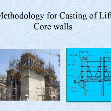
Methodology for Casting of Lift Core walls
For the construction of lift core walls , a combination of L&T wall formwork system with lift shaft system for ing internal shutters and Travelling climbing system for External shutters is suggested This gives the advantage of a faster progress for lift cores without waiting for the floor slab to complete
With the suggested methodology, the lift core walls can progress ahead independent of the slab casting
Typical section of a lift core wall showing inside and outside shutters with ing platform arrangement
Formwork details: •
• • •
•
L&T Wall formwork with Travelling climbing system (CB 150F) used for Outer face of core wall. L&T Lift shaft platform system used with wall formwork for Inner face / opening. Outer shutter s are ed on a pair of brackets. Each pair of shutter with brackets having in-built safety such as necessary handrails for concreting & shutter platforms. Tower cranes used for lifting of shutters from one
SALIENT FEATURES
SYSTEM DESCRIPTION: The lift shaft platform system is suitable for lift core / RC-walls close to each other.
The Climbing Formwork System comprises of shaft main beam resting in pockets provided in the already cast RC-Wall. The cross beams are provided over this. Wooden planks over the cross beams form the lift shaft platform. Leveling of the platform is possible by operation of spindle within the gravity pawls.
The main beam have gravity pawls which unlocks it self from the pockets when lifted upwards and lock itself at the next pocket location. The gravity pawls are hinged and have one way movement only, the platform thus has high levels of safety. The platform as a whole alongwith the main beam, gravity pawls, cross beams and platform can be lifted as one unit.
Ideal system for speedy construction. Eliminates the need for scaffolding to the Wall Formwork. High levels of safety - full proof system. Minimum skill & operation for anchoring & shuttering at each level. Sling from Crane
Sling from
This platform facilitates resting Crane of the wall formwork and alignment. To be cast
To be cast
Lifting Bkt.
Pocket to suit Pawl
Lift shaft platform resting in the pockets
Freshly cast
Pocket to suit Pawl
Freshly cast Lift shaft Platform
Climbing Pawl Pocket to suit Pawl
Climbing Pawl
lift shaft platform being lifted to the next level
Already Cast Wall
Already Cast Wall Lift shaft Platform
Details showing the arrangement of Lift shaft platform and shutters inside
VERTICAL WALER ROLL BACK OF SHUTTERS
SHIFTING OF TO NEXT LEVEL USING CRANE
Details showing the climbing system 150 F and shutters outside
Project: TSI Business Park At Hyderabad Contractor: M/s. Shapoorji Pallonji & Co Ltd.
• L&T Formwork System is being used for the construction of the LIFT CORE WALLS
•The total catered area is : 2 sets of lift core(typ floor) of phase I=1140 sqm 2 sets of lift core(typ floor) of phase II/III=1650 sqm The total catered area :2790 sqm
Structure details • Total number of lift core = 5 (Two in phase I, Two in phase-II and One in phase3) • Thickness of wall 230mm (Inner) & 350 mm/500mm (Outer) • Total number of vertical floors/ pours is 23 • Pouring height per lift 4.00m (max.) • The formwork is designed for: Design lateral concrete Pressure : 41.6 kN/Sq.m Allowable rate of pour :1.00 m /hour
Plan of Lift core wall shuttering for phase 1
Method statement 1. Casting of Starter with timber sides to suit wall dimensions. • 2. Assembly of formwork: (For 1st Pour) 3.Removal of formwork (for 1st Pour) 4.Erection of Inside/outside platforms and erection of formwork for second/next lift and concreting 5. De-shuttering of formwork and transfer to next level along with platforms with the help of crane. Step 4&5
repeated till the entire structure is
Method statement ..contd
Assembly of formwork: (For 1st Pour) 1. Placing of Shutter , check the line and level, then placing along the one side of the wall. 2. Inserting the Tierods upto other side wall surface covered by PVC pipe at the required locations (ie. As per scheme drawing & design calculations) 3. Placing of other side Shutter and check the edges with plumb, then placing other shutter s continuously. 4. Extending the Tie rods and fixing with Anchor plate & wingnut. 5. Placing Alignment props / ing bracket with Head adapter assembly & Foot adapter assembly. 6. ing the shutter s together by Splices with Connecting pins. 7. Fixing of Timber spacers (for wall thickness) on the top between the shutter s 8. Plumbing of shutters by using alignment struts / plumb bobs.,Checking the straight line/Checking the wall thickness at the top. 9. Universal inside corners and Universal outside fixing to be fixed according to the requirements of wall corners. 10.Stop anchors, Ties ,Anchor cones covered with PVC sleeves to be fixed for subsequent lift done for climbing system. Place the shaft pocket for shaft
LIFTING BRACKET
WORKING PLATFORM STD. STEEL WALER
TIE SYSTEM
H16 - BEAM STEEL WALER 12 MM DENS PLY
H-BEAMS
ALIGNMENT SYSTEM
12 MM THK PLY.
PLAN
C /S ELEVATION
WALL FORMWORK SYSTEM
Method statement ..contd Removal of formwork: • • •
First removal of Tie rods, Alignment struts, accessories Removal of shutters (each separately) with the help of crane Cleaning and shifting of shutter s (with alignment props / ing brackets) to next lift / length.
Method statement ..contd CB150F-making • •
• •
• • •
1. After dismantling the shutters, remove anchor cone using DK spanner and fix climbing cone. 2. Climbing bracket 150F – 2 nos (to suit stop anchor location which is already left in conc.) should be made as a set by bracing with NB 40 pipes and couplers. 3. Fix working platforms with ISMC runners and 2” thick planks. 4. Fix the Vertical waling (roler below the waler should sit over the bracket and scissor action spindle (in collapsed condition) with the help of Locking pins. 5. Brace the vertical walers properly with horizontal and Diagonal by NB 40 pipes & couplers. 6. Fix the vertical waler with Climbing bracket tightly with wedges to prevent movement. 7. Fix Handraill post on each bracket and hand railing at 2 levels should be done with NB 40 pipes & couplers.
Climbing system 150F with outside shutters
Method statement ..contd CB150F/Lift shaft platforms – erection •
• • •
• • •
1 Lift the entire assembly of climbing bracket 150F (by putting the sling on the top of the vertical walers) with the help of crane and place over the climbing cone correctly. Lock the climbing bracket with the locking pin to arrest upward movement of bracket from climbing cone head. 2 Follow the procedures described in the assembly of wall formwork, however the alignment props to be removed. 3. Vertical walers should be connected with horizontal walers using waling to bracket holders. 4. Top leveling of shutters and adjustment of verticality done by adjusting the screws at the bottom of the vertical walers. Aligning of shutters should be done with Scissor action spindles. 5. Check the verticality of the shutter using plumb bob. 6. Make lift shaft platform at ground with climbing pawl. 7. Shift the platform with help of crane & place it where the pockets already provided.
Botom View of shaft platform inside
Lift shaft platform with inside shutters
Method statement ..contd Dismantling and shifting to next level after concreting of typical pour • Roll back the shutters from concrete face. • Put the crane sling in the hook provided in the Vertical waler. • Take out the locking pin in the climbing bracket, so that the climbing bracket can be free for lifting. • Lift the entire assembly (including shutter and climbing bracket 150F assembly) and place it in next position. • Remove Inner shutter s & shift by crane to available place temporarily. (low level slab if any) • Lift the Inner shaft platform to next higher level. • This entire operation is repeated to complete the core wall • Folded Dowel bars will be taken out by chipping & Bent to required position. • Structural consultants should approve the slab casting & freestanding height of core walls.
Related Documents 3m3m1z
Lift Shaft l1928
December 2019 34
Lift 6m5s3a
April 2020 39
Rotating Shaft Whirling Of Shaft 3d4y4e
November 2019 72
Shaft Root Cause Shaft Failure 32h1p
December 2019 80
Propeler Shaft 5i379
December 2019 33