Light Sensor 2 42rx
This document was ed by and they confirmed that they have the permission to share it. If you are author or own the copyright of this book, please report to us by using this report form. Report 3b7i
Overview 3e4r5l
& View Light Sensor 2 as PDF for free.
More details w3441
- Words: 31,570
- Pages: 96
/ Lighting Controls
Product Catalog
It’s not just smarter. It’s easier. Acuity Controls is advanced lighting controls technology, service and from a single expert source. We offer one of the industry’s most extensive product portfolios for indoor and outdoor applications, single rooms to campuses to municipalities. Our product solutions include occupancy and photosensors, s, switches, fixture-level and wireless controls.
Printed on Recycled Paper
Contents
5 6 7 8
ABOUT SENSOR SWITCH Benefits
Sensor Technology
Sensorpedia: Occupancy Sensor Reference Guide
21 PRODUCT SELECTION GUIDE 22 Wall Switch Controls 32 Wireless Products 34 Ceiling Mount Sensors 40 Recessed Mount Sensors 44 Fixture Mount Sensors 50 Fixture Mount Interchangeable Lens Sensors 56 Wide View & Hallway Sensors 58 Outdoor Sensors 60 Power Packs 62 Micro Enclosure 64 Snap-Fit 69 Embedded
38 DAYLIGHTING CONTROL SENSORS 38 Ceiling Mount 42 Recessed Mount 48 Fixture Mount 54 Fixture Mount Interchangeable Lens 60
POWER PACKS
75 SPECIALTY PRODUCTS 76 Data Logging Monitoring System 78 Wire Guards 79 Masking Labels 79 Ballast Discriminator 81
WIRING DIAGRAMS
94
INDEX
The Sensor Switch product line from Acuity Controls provides an innovative, high quality and
Performance You Can Count On!
cost-effective controls solution for every application. Our occupancy sensors and photocell products are
•
Our ive Dual Technology (PIR/Microphonics™) looks and listens for occupants ensuring reliable detection
easy to install and easy to use. •
Reversible line and load wires make Sensor Switch products easy to install
•
Reliable-circuit protection tested for over 400,000 switching cycles
•
Continuous coverage patterns for a breadth of applications meeting your every need
•
5-year limited product warranty
•
Sensor Switch products aid in ensuring buildings meet applicable energy codes (Title 24, ASHRAE and IECC)
www.acuitycontrols.com / 5
BENEFITS Energy Savings The Sensor Switch offering of occupancy and daylight sensors are designed to optimize energy savings and enable sustainability. Our broad product offering provides solutions for applications requiring energy code compliance. Using innovative detection technologies that maximize energy savings we save you more!
Reliable Performance Sensor Switch is a leader in lighting control innovation, continuously developing technologies to enhance performance of our occupancy sensors and photocells providing trusted quality and reliability. We offer a broad selection of occupancy and daylight sensors to meet every application.
Ease of Installation Sensor Switch products are easy to install due to our patented features; reversible line and load wires (Miswire Protection), simple push button programming and our Convertible Neutral for Wall Switches! These powerful features save install time and eliminate extra costs on the job site!
6 / www.acuitycontrols.com
INNOVATING SENSOR TECHNOLOGY Sensor Switch is dedicated to providing innovative sensor technologies for applications requiring compliance to energy codes.
MICROPHONICS™ Microphonics technology utilizes a microphone inside the sensor to “hear” sounds indicating occupancy. This technology is perfect for rooms with obstructions where traditional PIR sensors cannot “see” the room occupant. Microphonics is superior as it provides better detection performance, requires less power, and does not transmit sound waves into the space, eliminating potential for interference.
MISWIRE PROTECTION Sensor Switch developed reversible line and load connections resulting in products that are impossible to wire backwards. This patented feature eliminates potential jobsite delays due to miswiring.
CONVERTIBLE NEUTRAL This is patent-pending technology allows a Sensor Switch Wall Switch occupancy sensor (WSX & WSD) to convert from a no neutral connection to a neutral and ground connection in seconds! If your application requires the use of a neutral connection, simply remove the ground link and wire per code, making installation quick and easy. One sensor does it all!
SELF-CALIBRATING DAYLIGHT CONTROLS All photocontrols have an automatic set-point calibration mode regardless of time-of-day or daylight conditions improving installation time!
www.acuitycontrols.com / 7
The Encyclopedia of Sensor Switch
SENSORPEDIA
This guide is intended to assist with choosing the appropriate Sensor Switch occupancy sensor for your space and application.
Each character or group of characters in a Sensor Switch model number indicates a specific feature or option for that particular sensor. The sections of this guide describe the choices available for each of the feature categories. By dividing up any Sensor Switch occupancy sensor model number into the parts described in this guide, the sensor’s full functionality can be determined. This guide will also better enable you to build your own model numbers by choosing from each category the features and options your project requires.
8 / www.acuitycontrols.com
PRODUCT NAMING CONVENTION GUIDE The product model numbers (i.e., CM 9) provide details on the particular product; such as, mounting type, power information, lens type etc. By understanding the product naming convention this will help you select the product that is correct for your application. The example below shows the categories that make up the model number CMR PDT 10 P.
Enclosure
Power
Detection
Lens
Options
CM
R
PDT
10
P
ENCLOSURES
10
POWER TYPE / WIRELESS
14
DETECTION TECHNOLOGY
15
LENS TYPE
16
OPTIONS
19
www.acuitycontrols.com / 9
ENCLOSURES
SENSORPEDIA
ENCLOSURES Sensor Switch occupancy sensors come in
COLOR CHOICES
a variety of different enclosure styles that are both functional and attractive while still being easy to install. The enclosure style for most sensors is indicated by the first few letters in their model number. BLACK *
LIGHT ALMOND*
WHITE
IVORY*
GRAY *
RED*
*Not available for all enclosures
WSX
Wall Switch WSX, WSX NL
WSD
H:
SSD
Physical Specs (not including mounting strap):
SENSORPEDIA
W: D:
Weight: Mounting: Color:
2.74” ( 6.96 cm ) 1.68” ( 4.27 cm )
Wall Switch WSD, SSD1 Physical Specs (not including mounting strap): H:
2.74” ( 6.96 cm )
D:
1.63” ( 4.14 cm )
W:
1.63” ( 4.14 cm ) 5 oz
Weight:
Single Gang Switch Box
Mounting:
White, Gray, Black, Red,
Color:
Ivory, Light Almond
SPODM
Wireless Wall Switch SPODMR WR
Physical Specs (not including mounting strap): H:
2.74” ( 6.96 cm )
D:
1.63” ( 4.14 cm )
W: Weight: Mounting: Color:
10 / www.acuitycontrols.com
1.68” ( 4.27 cm ) 5 oz
Single Gang Switch Box White, Gray, Black
Ivory, Light Almond
LWS
LWSH
1
1.68” ( 4.27 cm ) 5 oz
Single Gang Switch Box White, Gray, Black, Red Ivory, Light Almond
Available in White and Ivory only.
Large Area Wall Switch LWS, LWSH
Physical Specs (not including mounting strap): H:
4.96” ( 12.60 cm )
D:
1.70” ( 4.32 cm )
W: Weight: Mounting: Color:
3.10” ( 7.87 cm ) 7 oz
Single Gang Switch Box White, Ivory
Wireless Ceiling Mount CM XX WR Physical Specs:
Diameter: 4.50”
Depth:
3.5" Octagon Box
Color:
Mounting:
4 x 4 square junction box with or without two-gang mudring; directly to ceiling tile through 2.65” (6.7 cm) square opening
Weight:
6 oz
Color: White
WVR
HWR
(Low Voltage)
Color:
WV
HW
( 11.56 cm )
( 3.94 cm )
Ceiling Tile Surface 3.5" Octagon Box
Single Gang Handy Box White
Wall / Corner Mount WV, HW Physical Specs: H:
3.00” ( 7.62 cm )
D:
1.75” ( 4.45 cm )
W: Weight: Mounting:
Color:
3.60” ( 9.14 cm ) 4 oz
Directly to Corner or to
Ceiling using WV BR Bracket White
SENSORPEDIA
4.60” (square) ( 11.68 cm )
White
Width:
6 oz
Single Gang Handy Box
1.55”
Weight: Mounting:
Ceiling Surface
Recessed Ceiling Mount RM Physical Specs:
Diameter: 4.55”
Depth:
( 6.07 cm )
6 oz
Ceiling Mount CM Physical Specs:
( 11.56 cm )
Weight: Mounting:
RM
2.39”
CM
ENCLOSURES
CM
Wall / Corner Mount WVR2, HWR3 Physical Specs: H:
4.96” ( 12.60 cm )
D:
1.70” ( 4.32 cm )
W:
Weight: Mounting: Color:
3.10” ( 7.87 cm ) 7 oz
Single Gang Handy Box White, Ivory
WVR is the Line Voltage Enclosure of the WV 3 HWR is the Line Voltage Enclosure of the HW 2
www.acuitycontrols.com / 11
ENCLOSURES
Fixture Mount Interchangeable Lens Enclosures LSXR
LSXR
Physical Specs: H:
3.75” ( 9.50 cm )
D:
4.00” ( 10.20 cm )
W: Weight:
Mounting: Color:
CMB
HMB
6 oz
1/2” Knockout (7/8” hole) White
Fixture Mount Single Lens Enclosure (Indoor) CMB, HMB
SENSORPEDIA
Physical Specs:
Fixture Mounting Bracket (Indoor) FB3 Physical Specs:
3.63” ( 9.22 cm )
H:
5.00” ( 12.70 cm )
D:
1.50” ( 3.81 cm )
D:
1.35” ( 3.43 cm )
1/2” Knockout in Fixture
Mounting:
White
Color: White
Weight:
Mounting:
Color:
3.63” ( 9.22 cm )
W:
6 oz
Weight:
or Junction Box
Fixture/Pole Mount Single Lens Enclosure (Outdoor / Wet Location) SBO Physical Specs: H:
3.35” ( 8.51 cm ) or 4.88” ( 12.40 cm )
D:
4.00” ( 10.16 cm )
W: Weight: Mounting: Color:
12 / www.acuitycontrols.com
FB3
H: W:
SBO
2.50” ( 6.40 cm )
4.40” ( 11.18 cm ) 9 oz
1/2” Knockout (7/8” hole)
White, Black, Dark Bronze
2.00” ( 5.08 cm )
2.52 oz each (excluding nuts) 1/2” Knockout in Fixture or Junction Box
Embedded Small Box (Indoor) SB Physical Specs: H:
W: D:
Weight: Mounting:
Color:
SF
SFD
H:
W: D:
Weight: Mounting:
Color:
4.00” ( 10.16 cm )
Mounting:
in Fixture
Color:
(minimum depth 1.50”)
4.40” ( 11.18 cm ) 9 oz
1/2” Knockout (7/8” hole) White, Black
White, Black
SFOD
SFOR
Required Hole Size 1.125” Material Thickness 0.25” max White
D:
0.82” ( 2.08 cm )
Color:
White
3 oz
2.25” ( 5.71 cm )
x 1-5/16” W x 1” D cavity in fixture
1.18” ( 2.99 cm )
H:
Mounting:
Snaps into 2-3/16” H
2.60” ( 6.65 cm )
Physical Specs:
Weight:
4 oz
1.34” ( 3.40 cm )
Snap-Fit (Outdoor / Wet Location) SFOD, SFOR W:
1.38” ( 3.51 cm )
Embedded Micro Enclosure (Indoor) MSD, ES Physical Specs:
D:
MSOD
SENSORPEDIA
Color:
3.35” ( 8.51 cm )
Weight:
2.65” Square Opening
0.82” ( 2.08 cm )
ES
6 oz
D:
Mounting:
H:
W:
1.40” ( 3.56 cm )
2.25” ( 5.72 cm )
Weight:
MSD
3.40” ( 8.64 cm )
H:
W:
Embedded Small Box (Outdoor) SBG Physical Specs:
3.40” ( 8.64 cm )
Snap-Fit (Indoor) SF, SFD Physical Specs:
SBG
ENCLOSURES
SB
1.38” ( 3.51 cm ) 4 oz
Snaps into 2-3/16” H x 1-5/16” W x 1” D cavity in fixture White, Black
Embedded Micro Enclosure (Outdoor / Wet Location) MSOD Physical Specs: H:
1.34” ( 3.40 cm )
D:
1.18” ( 2.99 cm )
W: Weight: Mounting:
Color:
2.60” ( 6.65 cm ) 3 oz
Required Hole Size 1.125” Material Thickness 0.25” max
White, Black
www.acuitycontrols.com / 13
POWER TYPE
SENSORPEDIA
POWER TYPE This category specifies how a sensor is powered, as
In contrast, line voltage sensors are powered by and
well as its switching capabilities. By default, sensors
can switch line voltage without a power pack. Line
are powered by low voltage and require a power pack
voltage model numbers have the letter “R” inserted
to switch a circuit; therefore, no special characters
with the enclosure designation (e.g., CMR).
need to be added to the model number.
Line Voltage •
Sensors contain line voltage switching relays
•
Ideal for retrofit applications with concrete or inaccessible ceilings
•
Interchangeable line & load wires (Sensor Switch patented)
•
Impossible to wire backwards
•
Sensors capable of switching two poles independently are indicated by adding 2P to the model number (e.g., CMR 6 2P)
•
Sensors capable of simultaneously switching two phases (e.g., 208, 240, or 480 VAC) are indicated by adding 208 or 480 to the model number (e.g., CMR 6 480)
SENSORPEDIA
R
LV
WR
14 / www.acuitycontrols.com
Low Voltage •
Powered via power pack or other low voltage source
•
Used with a power pack to enable complete 20 Amp circuits to be switched
•
Enables multiple sensors to be used together to cover space
•
Allows sensor mounting without a junction box and utilizes convenient low voltage wiring (e.g., CM 6 2P)
Wireless / Battery •
Wireless sensor is powered by a lithium battery (e.g., CM 9 WR); Ideal for renovation applications that are difficult to wire through the walls
•
10 year battery life (at default sensor settings)
•
AA Lithium (1.5V) Battery
•
Wireless communicates to wireless wall switch (e.g., SPODMR WR)
PIR & PDT
This category specifies the detection
DETECTION TECHNOLOGY
DETECTION TECHNOLOGY
SENSORPEDIA
MICROPHONICS™ IVE INFRARED
technologies employed by Sensor Switch. There are two types of detection technologies, ive Infrared and ive Dual Technology. All sensors utilize PIR
PDT
technology by default.
IVE DUAL TECHNOLOGY
ive Infrared Technology (PIR) PIR sensors detect changes in the infrared energy given off by occupants as they move within the field-of-view of the sensor
•
The sensor “sees” the heat given off by the human body as it moves in and out of the beams, and triggers the occupancy mode
•
The sensors are fine-tuned to detect small motions even at great distances, while still preventing false trips
•
All Sensor Switch sensors have PIR technology
SENSORPEDIA
PDT
•
ive Dual Technology (PDT) •
PDT is the combination of two detection technologies, PIR and Microphonics™
•
The sensor will first “see” motion using ive Infrared, and then engages the Microphonics™ to “hear” sounds that indicate continued occupancy
•
Patented by Sensor Switch, ive Dual Technology using PIR and Microphonics is superior to alternatively used ultrasonic technology
•
•
Better and more reliable occupancy detection performance
•
Requires less power
•
Does not transmit sound waves into the space, eliminating potential for interference
The PDT suffix after the enclosure model number adds Microphonics™ detection to the sensor
www.acuitycontrols.com / 15
SENSORPEDIA
LENS TYPE
LENS TYPE
IVE INFRARED
It is important to select a lens type with a PIR coverage pattern that accommodates the space’s area requirements, but also its application. The following pages diagram the PIR coverage pattern of each lens style and describe the applications for which they are best suited.
WSX
Wall Switch Lens • •
6
10
3
Wall-to-Wall coverage
0 ft
WSD
Wall Switch Lens •
6
10
3
Large motion (e.g., walking) detection up to 50 ft (15.24 m)
LWSH
Wall-to-Wall coverage
30 to 48 in (76.20 to 121.92 cm) high mounting
0m 0 ft
3
6
9
12
9
18
27
36
Wall-to-Wall coverage
48 to 84 in (121.92 to 213.36 cm) high mounting
40
12.2
30
9.1
20
6
10
3
0 ft
0m
40
12.2
30
9.1
20
6
10
3
0 ft
0m
6
3
0m
3
6
20
10
0 ft
10
20
9.1
6
3
0m
3
6
9.1
30
20
10
0 ft
10
20
30
9.1
6
3
0m
3
6
9.1
30
20
10
0 ft
10
20
30
1.2 m 4 ft
0m 0 ft
3
6
9
12
9
18
27
36
1.2 m 4 ft
0 ft
0m
7
2.1
0m
3
6
9.1
12.2
0 ft
10
20
30
40
0m
3
6
9.1
12.2
0 ft
10
20
30
40
SIDE VIEW
•
Small motion (e.g., hand movements) detection up to 40 ft (12.19 m)
0m
TOP VIEW
•
16 / www.acuitycontrols.com
Small motion (e.g., hand movements) detection up to 40 ft (12.19 m)
Large Area High Mount Wall Switch Lens •
20
SIDE VIEW
•
6
10
TOP VIEW
•
3
0 ft
Wall-to-Wall coverage
Large Area Wall Switch Lens •
0m
Small motion (e.g., hand movements) detection up to 20 ft (6.10 m)
0 ft
LWS
3 10
SIDE VIEW
•
20
6 20
TOP VIEW
SENSORPEDIA
•
0m
1.2 m 4 ft
SIDE VIEW
Large motion (e.g., walking) detection greater than 36 ft (10.97 m), ~2025 sq ft
20
TOP VIEW
•
Small motion (e.g., hand movements) detection up to 20 ft (6.10 m), ~625 sq ft
6
High Bay 360º Lens • •
•
7
•
• •
0 ft
0m
15
4.6
HIGH VIEW
6
3
0m
3
6
9.1
6
3
0m 3
6
9.1
20
10
0 ft
10
20
30
20
10
0 ft 10
20
30
15
9.1
30
13.7
45
Recommended for walking motion detection from mounting heights between 8 ft (2.44 m) and 20 ft (6.10 m)
9.2
30
7.4
Initial detection of walking motion along sensor axes at distances of 2x the mounting height up to 15 ft (4.57 m) and 1.75x up to 20 ft (6.10 m)
• •
SIDE VIEW 0 ft
15
0m
4.6
Provides 12 ft (3.66 m) radial detection of small motion when mounted at 9 ft (2.74 m)
Initial detection will occur earlier when walking across sensor’s field of view than walking directly at sensor
Best choice for small motion (e.g., hand movements) detection Viewing angle of 56º in a 360º conical shaped pattern
TOP VIEW
24
5.4
18
3.6
12
1.8
6
0m
0 ft
1.8
6
3.6
9.2
7.4
5.4
3.6
1.8
0m
1.8
3.6
5.4
7.4
9.2
12
5.4
30
24
18
12
6
0 ft
6
12
18
24
30
18
7.4
24
9.2
30
LOW VIEW 0 ft
0m
9
2.7 5.4
SIDE VIEW 18 0 ft
9
0m
TOP VIEW
5.5 4.6 3.7 2.7 1.8 0.9 0m 0.9 1.8 3.7 2.7 3.7 4.6 1.8 5.5
18 15 12 9 6 3 0 ft 3 6 12 9 12 15 6 18
4.6
3.6 2.7 1.8 0.9 0 m 0.9 1.8 2.7 3.6
4.6
15
12
15
9
6
3
0 ft
3
6
9
12
5.4
18TOP
VIEW
0m
0 ft
2.7
Provides 12 ft (3.66 m) radial coverage when mounted to standard 9 ft (2.74 m) ceiling
3.7
1.8
0m
1.8
3.7
1.8
6
12
6
0 ft
6
12
3.7
12
8.5
28
4.3
14
0m
0 ft
4.3
14
8.5
28
8.5
28
4.3
14
0m
0 ft
4.3
14
8.5
28
8 to 15 ft (2.44 to 4.57 m) mounting heights provide 10 to 20 ft (3.05 to 6.10 m) radial coverage
Large Motion / Extended Range 360º Lens • • •
•
Best choice for large motion (e.g., walking) detection
Viewing angle of 67º in a 360º conical shaped pattern Provides 28 ft (8.53 m) radial coverage when mounted to standard 9 ft (2.74 m) ceiling
SIDE VIEW 0 ft
9
TOP VIEW
0m
2.7 8.5
6.4
4.3
2.1
0m
2.1
4.3
6.4
8.5
28
21
14
7
0 ft
7
14
21
28
7 to 15 ft (2.13 to 4.57 m) mounting heights provide 16 to 36 ft (4.88 to 10.97 m) radial coverage
Bi-Directional Hallway Lens • • • •
SENSORPEDIA
•
11
Excellent detection of extra large motion (e.g., forklifts) up to a 45 ft (13.72 m) mounting height
Small Motion / Standard Range 360º Lens •
10
Excellent detection of large motion (e.g., walking) up to a 35 ft (10.76 m) mounting height
LOW VIEW
4.6
Mini-Low Bay 360° Lens •
9
15 to 20 ft (4.57 to 6.10 m) radial coverage overlaps area lit by a typical high bay fixture
0 ft
LENS TYPE
•
Best choice for 15 to 45 ft (4.57 to 13.72 m) mounting heights
0m
Best choice for large motion (e.g., walking) detection
Viewing angle of 67º for hallway applications
Provides 28 ft (8.53 m) of coverage when mounted to standard 9 ft (2.74 m) ceiling 7 to 15 ft (2.13 to 4.57 m) mounting heights provide 16 to 36 ft (4.88 to 10.97 m) hallway coverage
SIDE VIEW 0 ft
0m
9
2.7
TOP VIEW
8.5
6.4
4.3
2.1
0m
2.1
4.3
6.4
8.5
28
21
14
7
0 ft
7
14
21
28
www.acuitycontrols.com / 17
13
End-of-Hallway Lens •
LENS TYPE
•
16
Large motion (e.g., walking) detection up to 130 ft (39.62 m)
Designed for 7 ft (2.13 m) high mounting at end of hall
SIDE VIEW
TOP VIEW
0 ft
0m
10
3
5
1.5
0 ft
0m
10
3
10
3
• •
SENSORPEDIA
27.4
39.6
0m
3
15.2
27.4
39.6
0 ft
10
50
90
130
0 ft
10
50
90
130
Large motion (e.g., walking) detection up to 70 ft (21.34 m)
Designed for 8 to 10 ft (2.44 to 3.05 m) high mounting in room corner
TOP VIEW
SIDE VIEW 0 ft 0 m
2.7 0m
3
6
9.1
12.2
0 ft
10
20
30
40
40
12.2
30
9.1
20
6
10
3
0 ft
0m
9.1
6
3
0m
3
6
9.1
30
20
10
0 ft
10
20
30
Universal 360° Lens •
•
•
Provides excellent detection of large motion (e.g., walking) when mounted between 15 to 40 ft (4.57 to 12.19 m) 15 to 20 ft (4.57 to 6.10 m) radial coverage overlaps area lit by a typical high bay fixture
Recommended for fixtures that have a 1:1 spacing to mounting height ratio or less (e.g., fixtures 30’ on center or less @ a 30’ mounting height).
SIDE VIEW
TOP VIEW
0 ft
0m
20
6.1
10
3
10
3
20
6.1
0 ft
0m
30
9.1
10
3
40
12.2
20
6.1
6.1
0m
6.1
20
0 ft
20
High Bay Bi-Directional Aisleway Lens • •
•
18 / www.acuitycontrols.com
15.2
Small motion (e.g., hand movements) detection up to 40 ft (12.19 m)
9
50
3
Wide View 120° Lens •
30
0m
Provides 50º bi-directional and 10º wide coverage pattern
1.2x mounting height equals approximate detection range in either direction Typical 40 ft (12.19 m) mounting detects 50 ft (15.24 m) in either direction
SIDE VIEW 0 ft 0 m 10 3
TOP VIEW
20 6
7
30 9.1
2.1
0 ft 0 m
40 12.2
7 15.2 50
7.6 25
0m 0 ft
7.6 25
15.2 50
2.1 15.2 50
7.6 25
0m 0 ft
7.6 25
15.2 50
OPTIONS
SENSORPEDIA
Following this series number, there may be additional characters in the model number that define the optional features
OPTIONS
The previous sections of this guide define the portion of the model number referred to as a sensor’s series number. included on the sensor. This section describes each option and its model number character suffix. The datasheet for each sensor series lists its available options.
2P AO & 2P AOP Alternating Off Relays •
• •
2P AO
Sequence of operation where both relays close during periods of occupancy, but only one opens during vacancy The relay left closed alternates in order to promote even lamp wear
•
•
• •
2P SZ
•
347
Allows sensor to be powered by and switch 347 VAC Used primarily in Canada
•
•
•
light level by controlling levels of 0-10 VDC dimmable ballasts
Provides a second occupancy time-out period that enables the lights to go to a dim setting before turning off Adjustable max/min dim setting
When using multiple low voltage sensors, only one sensor per zone needs to have dimming output
Photocontrol also has full on/off control during periods of occupancy
Provides a second occupancy time-out period that enables the lights to go to a dim setting before turning off
Provides maximum energy savings by first dimming down, then switching off, lighting during periods of sufficient daylight contribution from windows or skylights
Controls 0-10V dimmable fluorescent ballasts and LED drivers
DZ
Provides more advanced daylighting control for 2-Pole line voltage occupancy sensors Single shared set-point is used for both poles
Ideal for A/B (also called inboard/outboard) switching applications
Determines the necessary on/off combination of the two poles in order to maintain adequate lighting
•
Ideal for classrooms with individually controlled parallel rows of lights
Uses a relative set-point for the second pole, which is a percentage of the first pole’s set-point
HL High/Low Occupancy Operation • • •
• • •
HL
•
Lights are reduced to an energy saving minimum dim level after expiration of occupancy time delay If relay is wired, lights will switch off after a second time delay
LT
During manufacturing, the circuit board goes through a conformal coating process, making it corrosion resistant from moisture
Enables operating temperatures down to -40º F (-40º C) for PIR sensors and -4º F (-20º C) for PDT sensors Ideal for cold storage applications or bath/shower rooms with condensing steam
P Photocontrol • •
P
Features auto set-point calibration
Fully digital, all settings in foot-candles
On/Off mode • •
Photocontrol has full control during periods of occupancy Recommended for public areas, such as vestibules, corridors, or restrooms
Inhibit mode •
Photocontrol can prevent lights from turning on if adequate daylight is available, but cannot turn lights off Recommended for areas where people work (private and open offices)
R Isolated Low Voltage Relay •
Provides high/low control of a 0-10V dimmable fixture
HVOLT 347-480 VAC
•
•
Percentage Offset (Dual Zone) Mode •
LT Low Temperature / High Humidity •
Stepped Dimming (DUO) Mode
ADC
Photocontrol within sensor maintains total room
During unoccupied periods without sufficient daylight lights are dropped to low dim setting, insuring minimum light levels are maintained at night
•
•
ANL ANL Combination Dimming & Switching Photocontrol w/ High/Low Occupancy Operation •
Provides dimming output to control 0-10 VDC dimmable ballasts
DZ Dual Zone Photocontrol
Switching photocontrol controls other pole
ADC Photocontrol w/ Auto Dimming •
•
D
SENSORPEDIA
•
•
•
Occupancy controls one pole only
347 347 VAC
D Occupancy Controlled Dimming •
2P AOP version also includes switching photocontrol
2P-SZ Single Pole Switching Photocontrol •
2P AOP
• • •
R
Enables low voltage sensors to interface with a building management system
Provides dry closure via an SPDT, 1 Amp, 40 Volt relay The relay is energized when ALL connected sensors unoccupied
When using multiple sensors, only one sensor per zone needs to have a relay Note: Sensor must have power at all times for the relay to function.
HVOLT
Allows sensor to be powered by and switch 347 through 480 VAC Used primarily in Fixture Mount Sensors Used only in Single Pole Devices
www.acuitycontrols.com / 19
20 / www.acuitycontrols.com
PRODUCT SELECTION GUIDE
22
WALL SWITCH CONTROLS
32
WIRELESS PRODUCTS
34
CEILING MOUNT SENSORS
38
CEILING MOUNT DAYLIGHT CONTROLS
40
RECESSED MOUNT SENSORS
42
RECESSED MOUNT DAYLIGHT CONTROLS
44
FIXTURE MOUNT SENSORS
48
FIXTURE MOUNT DAYLIGHT CONTROLS
50
FIXTURE MOUNT INTERCHANGEABLE LENS SENSORS
54
FIXTURE MOUNT INTERCHANGEABLE LENS DAYLIGHT CONTROLS
56
WIDE VIEW & HALLWAY SENSORS
58
OUTDOOR SENSORS
60
POWER PACKS
62
MICRO ENCLOSURE
64
SNAP-FIT
69
EMBEDDED
www.acuitycontrols.com / 21
Wall Switch Sensors
WALL SWITCH CONTROLS
PRODUCT INFORMATION
WSX FAMILY Wall Switch Sensor
PRODUCT SELECTION GUIDE
ADDITIONAL INFORMATION
Overview The WSX Family of wall switch occupancy sensors provides simple and cost effective solutions for commercial and residential lighting control applications. All WSX Family sensors have a stylish low profile appearance, soft-click buttons, and provide small motion detection up to 20 ft (6.10 m), making them perfect for private offices, private rest rooms, closets, copy rooms, or any other small enclosed space. Additionally, all WSX Family sensors have a patent pending wiring method that enables them to function either with or without a neutral connection. WSX units come pre-configured for wiring without a neutral; however, if connection to neutral is required by code, contractors can convert the unit in seconds.
Features • ive Dual Technology (PDT) utilizes PIR/ Microphonics™ detection
All WSX Family sensors utilize 100% digital ive Infrared (PIR) detection. Dual Technology (PDT option) versions add Microphonics™ detection and are recommended for offices and rooms with obstructions. Additional versions include units with dual relays - perfect for bi-level applications, and units with an integrated night light - perfect for restrooms and residential applications.
•
Miswire protection, reversible line & load connections
•
Convertible neutral
•
Digital PIR detection - excellent RF immunity
•
Ruggedized assembly, vandal resistant lens standard
•
100% ive detection, no potential for interference with other building systems
•
Fully meets NEC 2011 Section 404.2C neutral requirements - no current leakage to ground when connected to neutral
•
Compatible w/ LEDs, electronic & magnetic ballasts, CFLs, & incandescents
•
Photocontrol standard (disabled by default)
•
Push-button programmable without removing cover plate - adjustable time delays & operating modes
•
White LED status Indicator
For additional product information, visit www.acuitycontrols.com.
PHYSICAL SIZE: 2.74" H x 1.68" W x 1.63" D (6.96 cm x 4.27 cm x 4.14 cm) (not including ground strap) WEIGHT: 5 oz MOUNTING: Single gang switch box MOUNTING HEIGHT: 30-48” (76.2-121.9 cm)
SPECIFICATIONS ELECTRICAL MAXIMUM LOAD/POLE (RELAY): 800 W @ 120 VAC 1200 W @ 277 VAC 1500 W @ 347 VAC MINIMUM LOAD: None MOTOR LOAD: 1/4 Hp FREQUENCY: 50/60 Hz WIRING DIAGRAM(S): See Figure # 1, 2, 3, 4 on Page 82
ENVIRONMENTAL OPERATING TEMP: Standard: 14° to 122°F (-10° to 50°C) LT Option (PIR): -40° to 122°F (-40° to 50°C) LT Option (PDT): -4° to 122°F (-20° to 50°C) RELATIVE HUMIDITY: Standard: 20 to 75% non-condensing LT Option: 20 to 90% non-condensing (electronics coated for corrosion resistance) ROHS COMPLIANT
COVERAGE PATTERN WSX
Wall Switch Lens
•
Large motion (e.g., walking) detection greater than 36 ft (10.97 m), ~2025 sq ft
•
Wall-to-Wall coverage
•
ive Dual Technology (Microphonics™) provides overlapping detection of human activity over the complete PIR coverage area; advanced filtering is utilized to prevent non-occupant noises from keeping the lights on
22 / www.acuitycontrols.com
20
6
10
3
0 ft
0m
6
3
0m
3
6
20
10
0 ft
10
20
1.2 m 4 ft 0m 0 ft
3
6
9
12
9
18
27
36
SIDE VIEW
Small motion (e.g., hand movements) detection up to 20 ft (6.10 m), ~625 sq ft
TOP VIEW
•
Wall Switch Sensors
PRODUCT INFORMATION
347
•
347 Voltage Allows sensor to be powered from and switch 347 VAC
•
Cover plate for 347 VAC sensors included LT
2P
• •
•
Low Temp/High Humidity Required for cold/humid areas
•
•
Sensor electronics are coated for corrosion resistance
•
Operates down to -40°F/C (-4°F/-20°C for PDT)
•
SINGLE RELAY
Includes two isolated relays, Pole 1 defaulted to Auto On, Pole 2 to Vacancy E nables separate time delay per pole - programmed via each pole’s push-button L Listed to switch different loads per pole - e.g. 277 VAC U lights on Pole 1 and 120 VAC fan on Pole 2
Operating mode (blank) SA VA
Voltage
1
Auto-On (default) or Vacancy Vacancy (default) or Auto-On Vacancy only
(blank) 347
Ultra low power White LED night light (24/7 operation)
•
C apable of powering over Ground (no Neutral required)
•
Manual On/Auto off operation of lights (default)
•
Available with Single or Dual Relays
Temp/Humidity
3
WH IV GY AL BK RD
White Ivory Gray Light Almond Black Red
Specifications subject to change.
Standard Low Temp/ High Humidity
WSX 2P ive Infrared (PIR) WSX PDT 2P Dual Technology (PIR/Microphonics™)
(blank)
(blank) 347
Pole 1 Auto-On Pole 2 Vacancy (default) Both Poles Vacancy (default) or Auto-On Both Poles Vacancy only
Color 3 120/277 VAC 347 VAC 2
WH IV GY AL BK RD
Temp/Humidity White Ivory Gray Light Almond Black Red
(blank) LT
Specifications subject to change.
Example: WSX PDT NL WH Voltage
4
ive Infrared (PIR) Dual Technology (PIR/Microphonics™) Dual Relay, ive Infrared (PIR) Dual Relay, Dual Technology (PIR/Microphonics™)
Standard Low Temp/ High Humidity
(blank) 347
Color 120/277 VAC 347 VAC 2
WH IV GY AL BK RD
Temp/Humidity
3
White Ivory Gray Light Almond Black Red
(blank) Standard LT Low Temp/High Humidity
Notes 1. Operating modes reprogrammable via push-button except for VA version 2. Wall plates included in white or ivory only for 347 VAC units 3. Matching wall plate provided for 120/277 VAC units 4. Units factory set to Vacancy (Manual On) Operating mode www.acuitycontrols.com / 23
PRODUCT SELECTION GUIDE
Voltage
2SA 2VA
(blank) LT
Example: WSX 2P 2SA 347 WH LT
Operating mode 1
WSX NL WSX PDT NL WSX 2P NL WSX PDT 2P NL
•
Color 120/277 VAC 347 VAC 2
Series
Series
Night Light I deal for bathrooms (hotel/hospital) or residential applications
Example: WSX PDT WH
WSX ive Infrared (PIR) WSX PDT Dual Technology (PIR/Microphonics™)
NIGHT LIGHT
•
Specifications subject to change.
Series
DUAL RELAY
NL
Dual Relay Ideal for bi-level switched rooms or restroom with light & fan
WALL SWITCH CONTROLS
OPTION INFORMATION
Wall Switch Sensors
WALL SWITCH CONTROLS
PRODUCT INFORMATION
WSD FAMILY Wall Switch Sensor
PRODUCT SELECTION GUIDE
ADDITIONAL INFORMATION
Overview The WSD wall switch sensor is a reliable work horse with powerful ive Infrared (PIR) detection technology as well as optional ive Dual Technology. This line of wall switch sensors are perfect for private offices, copy rooms, closets, or any small enclosed space without obstructions. All of Sensor Switch’s wall switch occupancy sensors are easy to install, and simple to use. Additionally, the WSD sensor has several On Modes and Switch Modes that can be programmed using the front push-button. For rooms with obstructions, the Dual Technology WSD PDT Series sensor is recommended. Additionally, all WSD Family sensors have a patent pending wiring method that enables them to function either with or without a neutral connection. WSD units come pre-configured for wiring without a neutral; however, if connection to neutral is required by code, contractors can convert the unit in seconds.
Features • ive Dual Technology (PDT) utilizes PIR/ Microphonics™ detection •
Miswire protection, reversible line & load connections
•
Convertible neutral
•
Digital PIR detection - excellent RF immunity
•
Small motion detection to 20 ft
•
Self-grounding mounting strap
•
Photocontrol standard (disabled by default)
•
Compatible w/ LEDs, electronic & magnetic ballasts, CFLs, & incandescents
•
Push-button programmable without removing cover plate - adjustable time delays & operating modes
•
Green LED status Indicator
For additional product information, visit www.acuitycontrols.com.
PHYSICAL SIZE: 2.74" H x 1.68" W x 1.63" D (6.96 cm x 4.27 cm x 4.14 cm) (not including ground strap) WEIGHT: 5 oz MOUNTING: Single gang switch box MOUNTING HEIGHT: 30-48” (76.2-121.9 cm)
SPECIFICATIONS ELECTRICAL MAXIMUM LOAD/POLE (RELAY): 800 W @ 120 VAC 1200 W @ 277 VAC 1500 W @ 347 VAC MINIMUM LOAD: None MOTOR LOAD: 1/4 Hp FREQUENCY: 50/60 Hz WIRING DIAGRAM(S): See Figure # 1, 2, 3, 4 on Page 82
ENVIRONMENTAL OPERATING TEMP: Standard: 14° to 122°F (-10° to 50°C) LT Option (PIR): -40° to 122°F (-40° to 50°C) LT Option (PDT): -4° to 122°F (-20° to 50°C) RELATIVE HUMIDITY: Standard: 20 to 75% non-condensing LT Option: 20 to 90% non-condensing (electronics coated for corrosion resistance) ROHS COMPLIANT
COVERAGE PATTERN
WSD
Wall Switch Lens • •
Large motion (e.g., walking) detection up to 50 ft (15.24 m)
6
10
3
0 ft
24 / www.acuitycontrols.com
0m
6
3
0m
3
6
20
10
0 ft
10
20
1.2 m 4 ft
0m 0 ft
3
6
9
12
9
18
27
36
SIDE VIEW
Wall-to-Wall coverage
20
TOP VIEW
•
Small motion (e.g., hand movements) detection up to 20 ft (6.10 m)
Wall Switch Sensors
PRODUCT INFORMATION
WALL SWITCH CONTROLS
OPTION INFORMATION 347
•
347 Voltage Allows sensor to be powered from and switch 347 VAC
•
Cover plate for 347 VAC sensors included LT
2P
•
Dual Relay I deal for bi-level switched rooms or restroom with light & fan
•
Includes two isolated relays, Pole 1 defaulted to Auto On, Pole 2 to Vacancy
•
Low Temp/High Humidity Required for cold/humid areas
•
•
Sensor electronics are coated for corrosion resistance
E nables separate time delay per pole - programmed via each pole’s push-button
•
Operates down to -40°F/C (-4°F/-20°C for PDT)
•
L Listed to switch different loads per pole - e.g. 277 VAC U lights on Pole 1 and 120 VAC fan on Pole 2
SINGLE RELAY
Example: WSD PDT WH
Specifications subject to change.
Series
Operating mode
WSD ive Infrared (PIR) WSD PDT Dual Technology (PIR/Microphonics™)
(blank) SA VA
Auto-On (default) or Vacancy Vacancy (default) or Auto-On Vacancy only
(blank) 347
Color 120/277 VAC 347 VAC 2
WH IV GY AL BK
Temp/Humidity
3
White Ivory Gray Light Almond Black
Standard Low Temp/High Humidity
Example: WSD PDT 2P 2SA WH
Specifications subject to change.
Series
Operating mode
WSD 2P ive Infrared (PIR) WSD PDT 2P Dual Technology (PIR/Microphonics™)
(blank) 2SA
(blank) LT
1
Pole 1 Auto-On Pole 2 Vacancy (default) Both Poles Vacancy (default) or Auto On
Voltage (blank) 347
Color 120/277 VAC 347 VAC 2
WH IV GY AL BK
Temp/Humidity
3
White Ivory Gray Light Almond Black
(blank) LT
Standard Low Temp/High Humidity
Notes 1. Operating modes reprogrammable via push-button except for VA version 2. Wall plates included in white or ivory only for 347 VAC units 3. Matching wall plate provided for 120/277 VAC units www.acuitycontrols.com / 25
PRODUCT SELECTION GUIDE
DUAL RELAY
Voltage
1
Wall Switch Sensors
WALL SWITCH CONTROLS
PRODUCT INFORMATION
SSD
Wall Switch Sensor
*Cover Plate Not Included
Overview The SSD is a cost effective wall switch sensor with powerful ive Infrared (PIR) detection technology. The wall switch sensor is easy to install and simple to use. It is ideal for private offices, copy rooms, closets, or any small enclosed space without obstructions. A programmable time delay ensures that once the room is vacated the sensor will time out and turn off the lights.
Features
Sensor Operation SSD sensors detect changes in the ive Infrared (PIR) energy given off by occupants as they move within the field-ofview. Once occupancy is detected, an internal relay switches on the connected lighting load. In an SSD VA (Vacancy/Manual On) sensor, the unit’s push button must first be pressed to initiate the lights on. After the lights are turned on, an internal timer keeps them on during brief periods of inactivity. Once the time delay has expired, lights are turned off automatically. The default time delay is 10 minutes - chosen in order to maximize energy savings while preventing false-offs. This timer is programmable from 30 seconds to 30 minutes, and is reset every time occupancy is re-detected. Patented LampMaximizer® technology is also present in these sensors, providing an additional minimum on time (disabled by default) to be utilized if desired.
Miswire protection, reversible line & load connections
•
PIR detection - excellent RF immunity
•
Small motion detection to 20 ft
•
Self-grounding mounting strap
•
No neutral connection required
•
No minimum load and no current leakage to load
•
Compatible w/ Electronic & Magnetic Ballasts, CFLs, & Incandescents
•
Push-button programmable without removing cover plate - adjustable time delays & operating modes
•
Integrated LampMaximizer® minimum on time (patented) provides increased
•
Fluorescent lamp life - disabled by default
•
Non-volatile settings memory
•
Green LED status Indicator
For additional product information, visit www.acuitycontrols.com.
ADDITIONAL INFORMATION
SPECIFICATIONS ELECTRICAL
PHYSICAL
PRODUCT SELECTION GUIDE
•
ENVIRONMENTAL OPERATING TEMP 14º to 122º F (-10º to 50º C) RELATIVE HUMIDITY: 20 to 75% non-condensing ROHS COMPLIANT
MAXIMUM LOAD 800 W @ 120 VAC 1200 W @ 277 VAC Fluorescent/Incandescent loads only MINIMUM LOAD: None MOTOR LOAD: 1/4 HP FREQUENCY: 50/60 Hz (timers are 1.2x for 50 Hz) WIRING DIAGRAM(S): See Figure # 5 on Page 83
SIZE: 2.74”H x 1.68”W x 1.63”D (6.96 cm x 4.27 cm x 4.14 cm) (not including ground strap) WEIGHT: 5 oz MOUNTING: Single Gang Switch Box MOUNTING HEIGHT: 30-48 in (76.2-121.9 cm)
COVERAGE PATTERN
SSD
Wall Switch Lens • •
Large motion (e.g., walking) detection up to 50 ft (15.24 m)
6
10
3
0 ft
ORDERING INFORMATION Series SSD
0m
6
3
0m
3
6
20
10
0 ft
10
20
0m 0 ft
3
6
9
12
9
18
27
36
Example: SSD WH
Specifications subject to change. Operating Mode
1
ive Infrared (PIR)
1.2 m 4 ft
SIDE VIEW
Wall-to-Wall coverage
20
TOP VIEW
•
Small motion (e.g., hand movements) detection up to 20 ft (6.10 m)
Voltage
Color
2
(blank)
Auto On (default) or Vacancy
(blank)
120/277 VAC
WH
White
SA
Vacancy (default) or Auto On
120
120 VAC only
IV
Ivory
VA
Vacancy only Notes: 1. Operating Modes reprogrammable via push-button except for VA version 2. Cover Plate Not Included
26 / www.acuitycontrols.com
Wall Switch Sensors
PRODUCT INFORMATION occupancy is detected, a self-contained relay switches the connected lighting load on. The sensor is line powered and can switch a range of line voltages. An internal timer, factory set at 10 minutes, keeps the lights on during brief periods of inactivity. This timer is push-button programmable from 30 seconds to 20 minutes, and is reset every time occupancy is re-detected. This state-of-the-art design requires no field calibration or sensitivity adjustments.
•
Small Motion Detection up to 20 ft (6.10m)
Sensor Operation The sensor detects changes in the infrared energy given off by occupants as they move within the field-of-view. When
•
30 sec to 20 min Time Delay
•
Push-Button Programmable
•
Green LED status Indicator
WSD LV Wall Switch Sensor
Features • PIR Occupancy Detection - excellent RF immunity
WALL SWITCH CONTROLS
Overview The WSD LV Series is a low voltage wall switch occupancy sensor that is stylish, easy to install, and simple to use. Ideal for private offices, copy rooms, closets, or any small enclosed space without obstructions, the WSD LV uses the industry’s best ive Infrared (PIR) technology to achieve excellent small motion detection up to 20 ft. A programmable time delay ensures that once the room is vacated the sensor will time out and turn off the lights. WSD LV sensors also have additional On Modes and Switch Modes that are all fully programmable using the front push-button. For rooms with obstructions the WSD PDT LV should be considered.
OPERATIONAL MODES On Modes (Default) Automatic On - The sensor automatically turns the lights on when the sensor detects occupancy. Reduced Turn-On - The sensor is set to initially only detect large motions, effectively ignoring any reflected PIR signals while still sensing occupants when they enter the room. Once on, the sensor returns to maximum sensitivity.
Switch Modes (Default) Predictive Off - Pressing the switch overrides the lights off and temporarily disables the occupancy detection. After an exit time delay (default 10 seconds) the occupancy detection reactivates and monitors for an additional grace period time (default 5 seconds). If no occupancy is detected during this period, the sensor will revert to Automatic On operation. If occupancy is detected, the sensor will remain in Permanent Off mode requiring the switch to be pressed again in order to restore the sensor to Automatic On.
Permanent Off - Pressing the push-button switch will turn the lights off. The lights will remain off regardless of occupancy until the switch is pressed again, restoring the sensor to Automatic On mode. Switch Disable - Prevents from manually turning off the lights via the push-button.
For additional product information, visit www.acuitycontrols.com.
ADDITIONAL INFORMATION
SPECIFICATIONS ELECTRICAL
PHYSICAL
ENVIRONMENTAL
PRODUCT SELECTION GUIDE
OPERATING TEMP: 14º to 160º F (-10º to 71º C) STORAGE TEMP: -14º to 160º F (-26º to 71º C) RELATIVE HUMIDITY: 20 to 90% non-condensing ROHS COMPLIANT
MAXIMUM LOAD: 800 W @ 120 VAC 1200 W @ 277 VAC 1500 W @ 347 VAC MINIMUM LOAD: None MOTOR LOAD: 1/4 HP FREQUENCY: 50/60 Hz WIRING DIAGRAM(S): See Figure # 7 on Page 83
SIZE: 2.74”H x 1.68”W x 1.63”D (6.96cm x 4.27cm x 4.14cm) WEIGHT: 5 oz MOUNTING: Single Gang Switch Box MOUNTING HEIGHT: 30-48 in (76.2 - 121.9 cm) COLORS: White, Ivory, Gray, Lt. Almond, Black
COVERAGE PATTERN WSD
Wall Switch Lens • •
Large motion (e.g., walking) detection up to 50 ft (15.24 m)
6
10
3
0 ft
0m
6
3
0m
3
6
20
10
0 ft
10
20
1.2 m 4 ft 0m 0 ft
3
6
9
12
9
18
27
36
SIDE VIEW
Wall-to-Wall coverage ive Dual Technology (Microphonics™) provides overlapping detection of human activity over the complete PIR coverage area; advanced filtering is utilized to prevent nonoccupant noises from keeping the lights on
20
TOP VIEW
• •
Small motion (e.g., hand movements) detection up to 20 ft (6.10 m)
OPTION INFORMATION R
LT
•
Low Voltage Relay Enables sensors to interface with other systems (e.g. BMS, lighting s)
•
Low Temp/High Humidity Required for cold/humid areas
•
Provides dry closure via a SPDT, 1 amp, 30 volt relay (resistive loads only)
•
Sensor electronics are coated for corrosion resistance
•
Operates down to -40°F/C (-4°F/-20°C for PDT)
ORDERING INFORMATION Series WSD LV WSD PDT LV
Example: WSD LV R WH LT
Specifications subject to change. Relay
ive Infrared (PIR) Dual Technology (PDT)
(blank) R
Color None Low Voltage Relay
WH White IV Ivory GY Gray
Temp/Humidity AL BK
Light Almond Black
(blank) Standard LT Low Temp/High Humidity
www.acuitycontrols.com / 27
Large Area Wall Switch Sensor
WALL SWITCH CONTROLS
PRODUCT INFORMATION
LWS(H)
Large Area Wall Switch Sensor
Overview Large Area Wall Switch sensors are ideal products to use when retrofitting classrooms, large storage centers or open spaces where a coverage pattern larger than a decorator sensor’s is needed, and where installing a low voltage systems is cost prohibitive. The LWS Series sensors surface mount at standard switch height, while the LWSH Series sensors surface mount from 4 to 7 ft (1.22 to 2.13 m). All styles are available with either ive Infrared (PIR) detection or Dual Technology (PIR/Microphonics™) detection for rooms with obstructions. The LWS and LWSH Series are line powered and available with one or two poles.
Features • Miswire protection, reversible line & load connections •
Small Motion detection up to 40 ft (12.19 m)
•
Self-Contained Relay(s), No Power Pack(s) Required
•
3-Way & 4-Way Switching Compatible
•
No Minimum Load
•
Adjustable Time Delay
•
Green LED status Indicator
COVERAGE PATTERN
LWS
Large Area Wall Switch Lens • •
LWSH
30 to 48 in (76.20 to 121.92 cm) high mounting ive Dual Technology (Microphonics™) provides overlapping detection of human activity over the complete PIR coverage area; advanced filtering is utilized to prevent nonoccupant noises from keeping the lights on
12.2
30
9.1
20
6
10
3
0 ft
0m
9.1
6
3
0m
3
6
9.1
30
20
10
0 ft
10
20
30
1.2 m 4 ft 0m
3
6
9.1
12.2
0 ft
10
20
30
40
SIDE VIEW
•
Wall-to-Wall coverage
40
TOP VIEW
PRODUCT SELECTION GUIDE
•
Small motion (e.g., hand movements) detection up to 40 ft (12.19 m)
Large Area High Mount Wall Switch Lens • • •
Wall-to-Wall coverage
28 / www.acuitycontrols.com
12.2
30
9.1
20
6
10
3
0 ft
0m
9.1
6
3
0m
3
6
9.1
30
20
10
0 ft
10
20
30
0 ft
0m
7
2.1 0m
3
6
9.1
12.2
0 ft
10
20
30
40
SIDE VIEW
48 to 84 in (121.92 to 213.36 cm) high mounting ive Dual Technology (Microphonics™) provides overlapping detection of human activity over the complete PIR coverage area; advanced filtering is utilized to prevent nonoccupant noises from keeping the lights on
40
TOP VIEW
•
Small motion (e.g., hand movements) detection up to 40 ft (12.19 m)
Large Area Wall Switch Sensor
PRODUCT INFORMATION
SPECIFICATIONS ELECTRICAL
PHYSICAL
ENVIRONMENTAL OPERATING TEMP: 14º to 85º F (-10º to 29º C) STORAGE TEMP: -14º to 160º F (-26º to 71º C) RELATIVE HUMIDITY: 20 to 90% non-condensing ROHS COMPLIANT (non-Photocontrol versions)
MAX LOAD / POLE: (1 Phase Only) 13 Amps @ 120-347 VAC FREQUENCY: 50/60 Hz Timers are 1.2 x for 50 Hz MOTOR LOAD: 1/4 HP each pole WIRING DIAGRAM(S): See Figure # 15 & 16 on Page 86
ENCLOSURE: Surface Mount SIZE: 4.96”H x 3.10”W x 1.70” D (12.60 cm x 7.87 cm x 4.32 cm) WEIGHT: 7 oz MOUNTING: Single Gang Switch Box MOUNTING HEIGHT: LWS: 30-48“ ( 76.2-121.92 cm) LWSH: 48-84” (121.92-213.36 cm) COLOR: White, Ivory
WALL SWITCH CONTROLS
For additional product information, visit www.acuitycontrols.com.
ADDITIONAL INFORMATION
OPTION INFORMATION 347
•
347 Voltage Allows sensor to be powered and switch 347 VAC
Example: LSW 2P WH
Specifications subject to change.
Series
# of Poles
Voltage
Color
LWS
ive Infrared (PIR)
(blank)
1-Pole
(blank)
120/277 VAC
WH
White
LWS PDT
Dual Technology (PDT)
2P
2-Pole
347
347 VAC
IV
Ivory
LWSH
ive Infrared (PIR)
LWSH PDT
Dual Technology (PDT)
OPTIONAL WALL PLATES
For additional product information, visit www.acuitycontrols.com.
The WS BPX plate comes with the 2-pole models. Others can be ordered separately.
WS SPX I/W
WS SPX3 I/W
WS BPX I/W
WS BPX3 I/W
www.acuitycontrols.com / 29
PRODUCT SELECTION GUIDE
ORDERING INFORMATION
Low Voltage Switches
WALL SWITCH CONTROLS
PRODUCT INFORMATION
SWITCHPOD Sensor Interface Switch
Features • Used with standard occupancy sensors for manual-on applications
SwitchPods are all single gang decorator style devices available as single or dual switch units. Versions are also available that work in 3-way applications and/or have a 0-10 VDC dimming output. Units defaulted to dual manual-on operation are also available. For digital solutions to bi-level lighting applications, nLight Enabled wall stations (WallPods), power packs, and sensors are necessary.
PHYSICAL SIZE: 2.74" H x 1.68" W x 1.63" D (6.96 cm x 4.27 cm x 4.14 cm) (not including ground strap) WEIGHT: 2 oz MOUNTING: Single gang switch box or low voltage ring
ORDERING INFORMATION
Alternative usage as override switch for auto-on applications
•
Single gang decorator style enclosure with 1 or 2 on/off switches
•
Finger-touch control
•
Programmable without removing switch plate
•
Optional dual manual-on operation
•
3X option enables unit for multi-way configurations (i.e., 3-way, 4-way, etc.)
•
Optional 0-10 VDC dimming control
SPECIFICATIONS ELECTRICAL OPERATING VOLTAGE: 12-24 VAC/VDC CURRENT DRAW: 5 mA DIMMING LOAD: 0-10 VDC, Sinks < 20 mA; ~40 Ballasts / Drivers @ 0.5 mA each RECOMMENDED POWER PACK: PP20 WIRING DIAGRAM(S): See Figure # 35, 36, 37, 38 on Page 92 - 93
ENVIRONMENTAL OPERATING TEMP: Standard: 14° to 122°F (-10° to 50°C) LT Option: -40° to 122°F (-40° to 50°C) RELATIVE HUMIDITY: Standard: 20 to 75% non-condensing LT Option: 20 to 90% non-condensing ROHS COMPLIANT
Example: SPODM WH
Specifications subject to change.
Series SPODM
•
For additional product information, visit www.acuitycontrols.com.
ADDITIONAL INFORMATION
PRODUCT SELECTION GUIDE
Overview The Push-Button SwitchPod (SPODM) Series of low voltage wall stations interface with Sensor Switch occupancy sensors and power packs in order to implement a wide range of single and bi-level switching applications. These switch devices provide an elegant and cost-effective way of deploying bi-level lighting control that meet energy and building codes without having to source special sensors or power packs.
Dimming
# of Switches/Default on Operation
1
Sensor Interface Switch
Multi-way
1
Color
Temp/Humidity
(blank)
None
(blank)
1 Switch/Auto On
(blank)
None
WH
White
(blank)
Standard
D
Dimming Operation (0-10VDC)
SA
1 Switch/Manual On
3X
IV
Ivory
LT
2P
2 Switches (Switch 1 Manual/Switch 2 Auto)
Multi-way (e.g. 3-way)
GY
Gray
Low Temp/ High Humidity
2P 2SA
2 Switches (both Manual)
AL
Light Almond
BK
Black Notes 1. Not available with 2 switch (2P) versions
30 / www.acuitycontrols.com
Preset Timer Switches
PRODUCT INFORMATION
ADDITIONAL INFORMATION
PTS
No minimum load requirement
•
Self-contained relay
•
Fixed or adjustable preset times
•
Optional audible timeout warning at 45, 30, and 15 sec
•
Optional flicker timeout warning at 2 and 1 min
•
Continuous led flash for last 30 sec of button’s time setting
•
Green LED time Indicators
SPECIFICATIONS ELECTRICAL
ENVIRONMENTAL OPERATING TEMP: Standard: 14° to 122°F (-10° to 50°C) LT Option: -40° to 122°F (-40° to 50°C) RELATIVE HUMIDITY: Standard: 20 to 75% non-condensing LT Option: 20 to 90% non-condensing ROHS COMPLIANT
MAXIMUM LOAD1 : 800 W @ 120 VAC 1200 W @ 277 VAC 1500 W @ 347 VAC MINIMUM LOAD: None MOTOR LOAD: 1/4 HP FREQUENCY: 50/60 Hz WIRING DIAGRAM(S): See Figure # 6 on Page 83
Example: PTS 60 WH
Specifications subject to change. Time Scale
Preset Timer Switch
No neutral connection required
•
Voltage
Color
Temp/Humidity
60
60 min. max
(blank)
120/277 VAC
WH
White
(blank)
Standard
720
720 min. max
347
347 VAC
IV
Ivory
LT
Low Temp/High Humidity
GY
Gray
AL
Light Almond
BK
Black Notes 1. Load specifications for fluorescent and incandescent lighting only See data sheet for LED specifications
www.acuitycontrols.com / 31
PRODUCT SELECTION GUIDE
Series
•
For additional product information, visit www.acuitycontrols.com.
PHYSICAL SIZE: 2.74" H x 1.68" W x 1.63" D (6.96 cm x 4.27 cm x 4.14 cm) (not including ground strap) WEIGHT: 5 oz MOUNTING: Single Gang Switch Box
ORDERING INFORMATION
PRESET TIMER SWITCHES
Features • Miswire protection, reversible line & load connections
WALL SWITCH CONTROLS
Overview The PTS 60 and PTS 720 Series preset timer switches provide a simple to use and simple to apply lighting control alternative to wall switch occupancy sensors. These elegant decorator style wall stations each provide six preset countdown timer selections as well as an on/off push-button. The PTS 60 and PTS 720 units are powered from 120/277 VAC (optional 347 VAC) and are intended to switch a line voltage lighting load or small motor load (see specifications). Additionally, the PTS 60 and PTS 720 can be applied without requiring a neutral wiring connection, making them ideal for retrofit applications.
Wireless Sensors
WIRELESS PRODUCTS
PRODUCT INFORMATION
WIRELESS PRODUCTS
Overview Sensor Switch's CM (PDT) xx WR Series of wireless occupancy sensors provide both ive Infrared (PIR) and Microphonics™ Dual Technology detection options. These battery operated sensors (with an estimated 10 year battery life) utilize RDT Wireless technology. They are designed to work with the SPODMR WR Series wall switch or other RDT Wireless devices to control a space's lighting.
Occupancy Sensors
Features • ive Dual Technology (PDT) utilizes PIR/ Microphonics™ detection •
100% wireless operation
•
RDT™ 902 MHz compliant
•
10-year battery life (at defaults)
•
360° coverage pattern
•
Digital PIR detection - excellent RF immunity
•
Simple push-button pairing
COVERAGE PATTERN
PRODUCT SELECTION GUIDE
9
10
Small Motion / Standard Range 360º Lens
TOP VIEW TOP VIEW
•
Best choice for small motion (e.g. hand movements) detection
•
360° conical shaped pattern
•
Provides ~12 ft (3.66 m) radial coverage (~500 ft 2) when mounted to standard 9 ft (2.74 m) ceiling
0 ft
•
8 to 15 ft (2.44 to 4.57 m) mounting heights provide ~10 to 20 ft (3.05 to 6.10 m) radial coverage
9
•
ive Dual Technology (Microphonics™) provides overlapping detection of human activity over the complete PIR coverage area; advanced filtering is utilized to prevent non-occupant noises from keeping the lights on
SIDE VIEW SIDE VIEW 00mft
0m
3.7
12 3.7
12
1.6
61.6
6
0 m 00ftm 0 ft 9 2.7
2.7 3.7
3.7
1.8
1.8
0m
0m
1.8
1.8
3.7
3.7
12
12
6
6
0 ft
0 ft
6
6
12
12
1.6
61.6
6
3.7
12 3.7
12
Large Motion / Extended Range 360º Lens •
Best choice for large motion detection (e.g. walking)
•
360° conical shaped pattern
•
Provides ~24 ft (7.32 m) radial coverage (~2000 ft 2) when mounted at 9 ft (2.74 m)
•
7 to 15 ft (2.13 to 4.57 m) mounting heights provide ~16 to 36 ft (4.88 to 10.97 m) radial coverage
•
Detection range improves when walking across beams compared to into beams
•
ive Dual Technology (Microphonics™) provides overlapping detection of human activity over the complete PIR coverage area; advanced filtering is utilized to prevent non-occupant noises from keeping the lights on
ADDITIONAL INFORMATION
TOP VIEW 8.5
28
4.3
14
SIDE VIEW 0 ft
0m
9
2.7
0 m 0 ft
8.5
6.4
4.3
28
21
14
2.1
0m
2.1
4.3
6.4
8.5
7
0 ft
7
14
21
28
4.3
14
8.5
28
For additional product information, visit www.acuitycontrols.com. SPECIFICATIONS
PHYSICAL SIZE: 4.5" Diameter (11.56 cm), 2.39" Deep (6.07 cm) WEIGHT: 6 oz MOUNTING: Ceiling Surface, 3.5" Octagon Box, Single Gang Handy Box COLOR: White BATTERY TYPE: AA Lithium (1.5V) EXPECTED BATTERY LIFE: ~10 years (at factory defaults) ORDERING INFORMATION Series CM
Specifications subject to change. Detection
Ceiling mount sensor
32 / www.acuitycontrols.com
ENVIRONMENTAL OPERATING TEMP: CM xx WR: -4° to 122° (-20° to 50° C) CM PDT xx WR: 25° to 122°F (-4° to 50° C) RELATIVE HUMIDITY: Standard: 20 to 90% non-condensing
Example: CM PDT 9 WR Coverage
Wireless Technology
(blank)
ive Infrared (PIR)
9
Small motion 360°
PDT
Dual Tech (PIR/Microphonics™)
10
Large motion 360°
WR
RDT™ Wireless
Wireless Switches
PRODUCT INFORMATION
ADDITIONAL INFORMATION
WIRELESS PRODUCTS
Features • Miswire protection, reversible line & load connections •
Neutral wire required-no current leakage to load
•
Adjustable time delays
•
Auto-On or Manual-On modes
•
Simple push-button pairing
•
2 Green LED status Indicators
Switch & Load Controller
For additional product information, visit www.acuitycontrols.com. SPECIFICATIONS ELECTRICAL
PHYSICAL SIZE: 2.74" H x 1.68"W x 1.63"D (6.96 cm x 4.27 cm x 4.14 cm) WEIGHT: 5 oz MOUNTING: Single gang switch box
ENVIRONMENTAL OPERATING TEMP: (-20° to 50° C) RELATIVE HUMIDITY: 20-75% non-condensing WIRELESS FREQUENCY: 902 MHz (RDT™) ROHS COMPLIANT
This equipment has been tested and found to comply with the limits for a Class B digital device, pursuant to part 15 of the FCC rules.
Series SPODMR WR
Specifications subject to change. Operating Mode
Wall switch
Example: SPODMR WR WH Color
Kit
(blank)
Auto on
WH
White
(blank)
None
SA
Manual on
IV
Ivory
K1
Includes CM 9 WR
GY
Gray
K2
Includes CM 10 WR
AL
Light Almond
K3
Includes CM PDT 9 WR
BK
Black
K4
Includes CM PDT 10 WR
www.acuitycontrols.com / 33
PRODUCT SELECTION GUIDE
MAXIMUM LOAD1 : 800 W @ 120 VAC/1200 W @ 277 VAC (Fluorescent/Incandescent) See data sheet for LED specs 1A @ 24 VAC/VDC MINUMUM LOAD: None MOTOR LOAD: 1/4HP LOAD FREQUENCY: 50/60 Hz WIRING DIAGRAM(S): See Figure # 1 on Page 82
Notes 1. Load specifications for fluorescent and incandescent lighting only See data sheet for LED specifications
ORDERING INFORMATION
WIRELESS PRODUCTS
Overview The SPODMR WR is a stylish, easy to install, and simple to use wall switch for use with paired CM (PDT) xx WR occupancy sensors or other RDT™ Wireless relay modules, kinetic switches, or plug-load controllers. Once wired, a few button pushes is all it takes to pair the switch to the desired sensors.
Ceiling Mount Sensors
CEILING MOUNT SENSORS
PRODUCT INFORMATION
CEILING MOUNT
Overview Ceiling mount sensors are offered in a multitude of configurations which address many applications. Lens options include large motion extended range, small motion standard range and bi-directional for hallways. Available in low voltage and line voltage models, these sensors are capable of covering an entire private office or small room by themselves. Multiple low voltage sensors can also work together to supply the ideal solution for oddly shaped rooms or large open office areas. A line voltage sensor provides one relay for a single-level control, while the 2-pole version provides a second relay for an additional level of control. For rooms with obstructions, these sensors are also offered with Dual Technology, which adds Microphonics™ detection to the ive Infrared (PIR) detection.
Sensors
ADDITIONAL INFORMATION
Features (All) • 30 sec to 30 min time delay •
Digital PIR detection - excellent RF immunity
•
Push-button programmable
•
Minimum On-Timer (LampMaximizer®)
•
Convenient test mode
•
Green LED status Indicator
Features (Line voltage) • Self-contained relay(s) •
No minimum load
•
Miswire protection, reversible line & load connections
For additional product information, visit www.acuitycontrols.com. SPECIFICATIONS
PHYSICAL
ELECTRICAL - LOW VOLTAGE
PRODUCT SELECTION GUIDE
SIZE: 4.55” diameter (11.56 cm) 1.55” deep (3.94 cm) WEIGHT: 6 oz MOUNTING: 3.5” octagon box, or single gang handy box COLOR: Matte White
OPERATING VOLTAGE: 12-24 VAC/VDC RECOMMENDED POWER PACK: PP20 CURRENT DRAW: Standard, 4 mA w/ R option, 16 mA WIRING DIAGRAM(S): See Figure # 8 on Page 84
ELECTRICAL - LINE VOLTAGE LOAD RATING: 800 W @ 120 VAC 1200 W @ 277 VAC 1500 W @ 347 VAC MOTOR LOAD: 1/4 HP FREQUENCY: 50/60 Hz WIRING DIAGRAM(S): See Figure # 9 & 10 on Page 84
ENVIRONMENTAL OPERATING TEMP: 14º to 160º F (-10º to 71º C) STORAGE TEMP: -14º to 160º F (-26º to 71º C) RELATIVE HUMIDITY: 20 to 90% non-condensing ROHS COMPLIANT
OPTION INFORMATION R
• •
P rovides dry closure via a SPDT, 1 amp, 30 volt relay (resistive loads only) P
• •
Low Voltage Relay Enables sensors to interface with other systems (e.g. BMS, lighting s)
Photocontrol A uto set-point calibration n/off mode: Full on/off control of O lighting during periods of occupancy with adequate daylight
•
I nhibit mode: Prevents lights from turning on if adequate daylight is available, but does not turn lights off
•
2-pole units operate in inhibit mode only
34 / www.acuitycontrols.com
ADC
Automatic Dimming Control Photocontrol Photocontrol within sensor maintains total room light level by controlling levels of 0-10 VDC dimmable ballasts/drivers
•
•
P hotocontrol also has full on/off control during periods of occupancy
•
P rovides a second occupancy time-out period that enables lights to go a dim setting before turning off LT
• •
DZ
•
Dual Zone Photocontrol Provides more advanced control than P option
D
•
Occupancy Controlled Dimming P rovides dimming output to control 0-10 VDC dimmable ballasts/drivers
•
UO operation: Determines necessary D on/off combination of poles in inboard/ outboard applications
•
P rovides a second occupancy time-out period that enables lights to go to a dim setting before turning off
•
P ercentage offset operation: Uses relative set-point for second pole in dual zone applications
•
Sinks <20mA; ~40 ballast/drivers
•
Adjustable max/min dim setting 347
Low Temp/High Humidity Sensor electronics are coated for corrosion resistance perates down to -40° F/C (-4°F/-20°C O for PDT)
•
347 Voltage A llows sensor to be powered and switch 347 VAC
Ceiling Mount Sensors
PRODUCT INFORMATION
6
High Bay 360º Lens • •
•
•
9
• •
Excellent detection of large motion (e.g., walking) up to a 35 ft (10.76 m) mounting height
Excellent detection of extra large motion (e.g., forklifts) up to a 45 ft (13.72 m) mounting height
LOW VIEW 0 ft
0m
15
4.6
HIGH VIEW
6
3
0m
3
6
9.1
6
3
0m 3
6
9.1
20
10
0 ft
10
20
30
20
10
0 ft 10
20
30
Best choice for small motion (e.g., hand movements) detection Viewing angle of 56º in a 360º conical shaped pattern
Provides 12 ft (3.66 m) radial coverage when mounted to standard 9 ft (2.74 m) ceiling
TOP VIEW
SIDE VIEW 0 ft
9
0m
2.7
8 to 15 ft (2.44 to 4.57 m) mounting heights provide 10 to 20 ft (3.05 to 6.10 m) radial coverage
3.7
1.8
0m
1.8
3.7
12
6
0 ft
6
12
Large Motion / Extended Range 360º Lens • • •
•
Best choice for large motion (e.g., walking) detection
Viewing angle of 67º in a 360º conical shaped pattern Provides 28 ft (8.53 m) radial coverage when mounted to standard 9 ft (2.74 m) ceiling
SIDE VIEW 0 ft
0m
9
2.7
TOP VIEW
8.5
6.4
4.3
2.1
0m
2.1
4.3
6.4
8.5
28
21
14
7
0 ft
7
14
21
28
• • •
4.6
15
9.1
30
13.7
45
3.7
12
1.8
6
0m
0 ft
1.8
6
3.7
12
8.5
28
4.3
14
0m
0 ft
4.3
14
8.5
28
8.5
28
4.3
14
0m
0 ft
4.3
14
8.5
28
7 to 15 ft (2.13 to 4.57 m) mounting heights provide 16 to 36 ft (4.88 to 10.97 m) radial coverage
Bi-Directional Hallway Lens •
0 ft
Best choice for large motion (e.g., walking) detection
Viewing angle of 67º for hallway applications
Provides 28 ft (8.53 m) of coverage when mounted to standard 9 ft (2.74 m) ceiling 7 to 15 ft (2.13 to 4.57 m) mounting heights provide 16 to 36 ft (4.88 to 10.97 m) hallway coverage
SIDE VIEW 0 ft
9
TOP VIEW
0m
2.7 8.5
6.4
4.3
2.1
0m
2.1
4.3
6.4
8.5
28
21
14
7
0 ft
7
14
21
28
www.acuitycontrols.com / 35
PRODUCT SELECTION GUIDE
•
11
15 to 20 ft (4.57 to 6.10 m) radial coverage overlaps area lit by a typical high bay fixture
Small Motion / Standard Range 360º Lens •
10
Best choice for 15 to 45 ft (4.57 to 13.72 m) mounting heights
0m
CEILING MOUNT SENSORS
COVERAGE PATTERN
Ceiling Mount Sensors
CEILING MOUNT SENSORS
PRODUCT INFORMATION
KEY SPECS SERIES
CM 6 CM 9 CM PDT 9 CM 10 CM PDT 10 CM 11 CM PDT 11 CMR 6 CMR 9 CMR PDT 9 CMR 10 CMR PDT 10 CMR 6 2P CMR 9 2P CMR PDT 9 2P CMR 10 2P CMR PDT 10 2P
LOW VOLTAGE
PRODUCT SELECTION GUIDE
COVERAGE PATTERN
Relay
CM 6 CM 9 CM PDT 9 CM 10 CM PDT 10 CM 11 CM PDT 11
(blank) R
Dimming/Photocontrol Choose One Only None Low Voltage Relay
(blank) D P ADC
None Occupancy Controlled High/Low Dimming Photocontrol Photocontrol with Dimming
Temp/Humidity (blank) LT
Standard Low Temp/High Humidity
Example: CMR 9 P 347 LT
Specifications subject to change. Dimming/Photocontrol Choose One Only
CMR 6 CMR 9 CMR PDT 9 CMR 10 CMR PDT 10
(blank) D P ADC
None Occupancy Controlled High/Low Dimming Photocontrol Photocontrol with Dimming
Voltage (blank) 347
Temp/Humidity 120/277 VAC 347 VAC
(blank) LT
Standard Low Temp/High Humidity
Example: CMR 9 2P DZ LT
Specifications subject to change.
Series
Dimming/Photocontrol Choose One Only
CMR 6 2P CMR 9 2P CMR PDT 9 2P CMR 10 2P CMR PDT 10 2P
(blank) P DZ
36 / www.acuitycontrols.com
Low 12-24 Low 12-24 Low 12-24 Low 12-24 Low 12-24 Low 12-24 Low 12-24 Line 120/277 Line 120/277 Line 120/277 Line 120/277 Line 120/277 Line 120/277 Line 120/277 Line 120/277 Line 120/277 Line 120/277
Example: CM 9 R P LT
Series
2-POLE, LINE VOLTAGE
POWER TYPE
PIR PIR Dual technology (PDT) PIR Dual technology (PDT) PIR Dual technology (PDT) PIR PIR Dual technology (PDT) PIR Dual technology (PDT) PIR PIR Dual technology (PDT) PIR Dual technology (PDT)
Specifications subject to change.
Series
LINE VOLTAGE
DETECTION
High Bay 360° Lens Small Motion/Standard Range 360° 9 Lens Small Motion/Standard Range 360° 9 Lens Large Motion/Extended Range 360° 10 Lens Large Motion/Extended Range 360° 10 Lens Bi-Directional Hallway Lens Bi-Directional Hallway Lens High Bay 360° Lens Small Motion/Standard Range 360° 9 Lens Small Motion/Standard Range 360° 9 Lens Large Motion/Extended Range 360° 10 Lens Large Motion/Extended Range 360° 10 Lens High Bay 360° Lens Small Motion/Standard Range 360° 9 Lens Small Motion/Standard Range 360° 9 Lens Large Motion/Extended Range 360° 10 Lens Large Motion/Extended Range 360° 10 Lens
None Photocontrol (inhibit only) Dual Zone Photocontrol
Voltage (blank) 347
Temp/Humidity 120/277 VAC 347 VAC
(blank) LT
Standard Low Temp/High Humidity
CEILING MOUNT DAYLIGHT CONTROLS
CEILING MOUNT DAYLIGHT CONTROLS
Switching & Dimming Sensors
SOLUTION TYPES
LIGHTS / KEY FULL ON
/ KEY
PC
PC
PC
AMPLE DAYLIGHT
Low voltage sensors are powered with 12-24 VAC/VDC. On/off Photocontrol sensors operate with a power pack (Model # PP20), enabling complete 20 Amp circuits to be controlled. Dimming Photocontrol sensors are capable of controlling any 0-10 VDC dimmable ballast or driver. Line voltage versions are also available that integrate a line switching relay and/or power off the line.
ADC PC
LIGHTS OFF LIGHTS FULL DIM LIGHTS FULL ON
LIGHTS OFFDIM LIGHTS FULL
ADC
100 hr. lamp burn-in timer
•
Fully digital control
•
Green LED status Indicator
LIGHTS FULL DIM
PC ADC
Combination On/Off & Dimming Control
PC ADC
AMPLE DAYLIGHT
DIMMING RANGE
DIMMING RANGE
DIMMING RANGE DIMMING RANGE
SET-POINT
SET-POINT SET-POINT
SET-POINT
SET-POINT SET-POINT
SET-POINT
SET-POINT
NO DAYLIGHT
NO NO DAYLIGHT DAYLIGHT
NO DAYLIGHT
NONO DAYLIGHT DAYLIGHT
NO DAYLIGHT
NO DAYLIGHT
SPECIFICATIONS ELECTRICAL - LOW VOLTAGE
LIGHTS OFF
LIGHTS FULL ON
AMPLE DAYLIGHT
ADC
ELECTRICAL - LINE VOLTAGE
LIGHTS FULL DIM
AMPLE DAYLIGHT
PC ADC
AMPLE DAYLIGHT
ENVIRONMENTAL OPERATING TEMP: 14º to 160º F (-10º to 71º C) STORAGE TEMP: -14º SET-POINT to 160º F (-26º to 71º C) RELATIVE HUMIDITY: 20 to 90% non-condensing ROHS COMPLIANT
NO DAYLIGHT
DIMMING RANGE
LOAD RATING: 800 W @ 120 VAC 1200 W @ 277 VAC 1500 W @SET-POINT 347 VAC MOTOR LOAD: 1/4 HP DIMMING LOAD: Sinks up to 20 mA or 40 ballasts/ NO DAYLIGHT drivers @ .5 mA each (0-10 VDC dimmable balasts/drivers only) WIRING DIAGRAM(S): See Figure # 22 - 28 on Page 88 - 89
DIMMING RANGE
OPERATING VOLTAGE: 12-24 VAC/VDC RECOMMENDED POWER PACK: PP20 CURRENT DRAW: Standard, 4 mA DIMMING LOAD: Sinks up to 20 mA or 40 ballasts/ drivers @ .5 mA each (0-10 VDC dimmable balasts/drivers only) WIRING DIAGRAM(S): See Figure # 22 - 28 on Page 88 - 89
DEADBAND
38 / www.acuitycontrols.com
Push-button programmable
•
PC ADC
PCADC ADC
PC PHYSICAL
Auto set-point calibration
•
AMPLE DAYLIGHT AMPLE AMPLE DAYLIGHT DAYLIGHT AMPLE DAYLIGHT AMPLE AMPLE DAYLIGHT DAYLIGHT AMPLE DAYLIGHT
/ KEY
SIZE: 4.55” diameter (11.56 cm) 1.55” deep (3.94 cm) WEIGHT: 6 oz MOUNTING: 3.5” octagon box, or single gang handy box COLOR: White
•
Automatic Dimming Control
DIMMING RANGE
NO DAYLIGHT
Features • Works as stand-alone unit or with occupancy sensors
ADC
DEADBAND DIMMING RANGE
DEADBAND
SET-POINT
Overview On/off Photocontrol and dimming sensors provide intelligent control of lighting for indoor daylight applications. Ideal for spaces with windows, such as vestibules, corridors, classrooms or offices, the sensors work by monitoring daylight conditions in a room, then controlling the lighting to ensure that adequate lighting levels are maintained.
LIGHTS OFF ON LIGHTS / KEY FULL
Automatic On/Off Switching
DEADBAND
PRODUCT SELECTION GUIDE
Ceiling Mount Daylight Controls
PRODUCT INFORMATION
SET-POINT
NO DAYLIGHT
OPTION INFORMATION
DZ
•
Dual Zone Provide second output that can control an additional zone of lighting
347
•
347 VAC Allows sensor to be powered from and switch 347 VAC
Stepped Dimming (Duo) Operation (PC Only) •
I deal for A/B (also called inboard/outboard) switching applications
•
etermines the necessary on/off combination of the two D poles in order to maintain adequate lighting
LT
•
Low Temp/High Humidity Sensor electronics are coated for corrosion resistance
•
Operates down to -40°F/C
CEILING MOUNT DAYLIGHT CONTROLS
Ceiling Mount Daylight Controls
PRODUCT INFORMATION
Percentage Offset Operation • Ideal for classrooms with individually controlled parallel rows of lights •
C sensors use a relative set-point for the second pole P that is a percentage of the first pole’s set-point
•
DC sensors enable control of an additional 0-10 VDC A dimmable ballast or driver at a selected level (voltage) higher than that of the primary zone
KEY SPECS SERIES
ENCLOSURE
CONTROL TYPE
Ceiling mount Ceiling mount Ceiling mount Ceiling mount Ceiling mount Ceiling mount
POWER TYPE [VDC/VAC]
On/off Dimming On/off & dimming On/off Dimming On/off & dimming
Low 12-24 Low 12-24 Low 12-24 Line 120/277 Line 120/277 Line 120/277
Example: CM PC DZ LT
LOW VOLTAGE
Series
Dual Zone
CM PC CM ADC CM PC ADC
(blank) DZ
Temp/Humidity Single Zone Dual Zone
(blank) LT
Standard Low Temp/High Humidity
Example: CMR PC DZ LT
LINE VOLTAGE
Series
Dual Zone
CMR PC CMR ADC CMR PC ADC
(blank) DZ
Voltage
Temp/Humidity
1
None Dual zone 2
(blank) 208 347 480
120/277 VAC 208/240 VAC 2 347 VAC 480 VAC 2
(blank) LT
Standard Low Temp/High Humidity
Notes 1. 480 and 208 option not available w/dual zone (DZ) 2. CMR PC Only
www.acuitycontrols.com / 39
PRODUCT SELECTION GUIDE
CM PC CM ADC CM PC ADC CMR PC CMR ADC CMR PC ADC
Recessed Mount Sensors
RECESSED MOUNT SENSORS
PRODUCT INFORMATION
RECESSED MOUNT
Overview Recessed mount sensors offer the reliable functionality of the standard ceiling mount with an architectural aesthetic. Recessed mount sensors are designed to fit inside a standard junction box making installation quick and easy. Lens options include large motion extended range and small motion standard range. Available in low voltage and line voltage models, these sensors are capable of covering an entire private office or small room by themselves. Multiple low voltage sensors can also work together to supply the ideal solution for oddly shaped rooms or large open office areas. A line voltage sensor provides one relay for a single-level control, while the 2-pole version provides a second relay for an additional level of control. For rooms with obstructions, these sensors are also offered with Dual Technology, which adds Microphonics™ detection to the ive Infrared (PIR) detection.
Sensors
Features (All) • 30 sec to 30 min time delay •
Digital PIR detection - excellent RF immunity
•
Push-button programmable
•
Minimum On-Timer (LampMaximizer®)
•
Convenient test mode
•
Green LED Status Indicator
Features (Line voltage) • Miswire protection, reversible line & load connections •
Self-contained relay(s)
•
No minimum load
COVERAGE PATTERN
9
Small Motion / Standard Range 360º Lens • • •
PRODUCT SELECTION GUIDE
• •
10
Best choice for small motion (e.g., hand movements) detection
TOP VIEW
SIDE VIEW
Viewing angle of 56º in a 360º conical shaped pattern
Provides 12 ft (3.66 m) radial coverage when mounted to standard 9 ft (2.74 m) ceiling
0 ft
0m
9
2.7
8 to 15 ft (2.44 to 4.57 m) mounting heights provide 10 to 20 ft (3.05 to 6.10 m) radial coverage ive Dual Technology (Microphonics™) provides overlapping detection of human activity over the complete PIR coverage area; advanced filtering is utilized to prevent non-occupant noises from keeping the lights on
3.7
1.8
0m
1.8
3.7
12
6
0 ft
6
12
Large Motion / Extended Range 360º Lens • • •
• •
Best choice for large motion (e.g., walking) detection
SIDE VIEW 0 ft
Viewing angle of 67º in a 360º conical shaped pattern Provides 28 ft (8.53 m) radial coverage when mounted to standard 9 ft (2.74 m) ceiling
9
TOP VIEW
0m
2.7 8.5
6.4
4.3
2.1
0m
2.1
4.3
6.4
8.5
28
21
14
7
0 ft
7
14
21
28
7 to 15 ft (2.13 to 4.57 m) mounting heights provide 16 to 36 ft (4.88 to 10.97 m) radial coverage ive Dual Technology (Microphonics™) provides overlapping detection of human activity over the complete PIR coverage area; advanced filtering is utilized to prevent non-occupant noises from keeping the lights on
ADDITIONAL INFORMATION
For additional product information, visit www.acuitycontrols.com. SPECIFICATIONS
PHYSICAL SIZE: 4.40” square (11.18 cm) WEIGHT: 6 oz MOUNTING: 4 x 4 square junction box with or without two-gang mudring; directly to ceiling tile through 2.65 (6.7 cm) square opening COLOR: White
40 / www.acuitycontrols.com
ELECTRICAL - LOW VOLTAGE OPERATING VOLTAGE: 12-24 VAC/VDC RECOMMENDED POWER PACK: PP20 CURRENT DRAW: Standard, 4 mA w/ R option, 16 mA WIRING DIAGRAM(S): See Figure # 8 on Page 84
ELECTRICAL - LINE VOLTAGE LOAD RATING: 800 W @ 120 VAC 1200 W @ 277 VAC 1500 W @ 347 VAC MOTOR LOAD: 1/4 HP FREQUENCY: 50/60 Hz WIRING DIAGRAM(S): See Figure # 9 & 10 on Page 84
ENVIRONMENTAL OPERATING TEMP: 14º to 160º F (-10º to 71º C) STORAGE TEMP: -14º to 160º F (-26º to 71º C) RELATIVE HUMIDITY: 20 to 90% non-condensing ROHS COMPLIANT
3.7
12
1.8
6
0m
0 ft
1.8
6
3.7
12
8.5
28
4.3
14
0m
0 ft
4.3
14
8.5
28
Recessed Mount Sensors
PRODUCT INFORMATION
COVERAGE PATTERN
RM 9 RM PDT 9 RM 10 RM PDT 10 RMR 9 RMR PDT 9 RMR 10 RMR PDT 10 RMR 9 2P RMR PDT 9 2P RMR 10 2P RMR PDT 10 2P
DETECTION
Small Motion/Standard Range 360° 9 Lens Small Motion/Standard Range 360° 9 Lens Large Motion/Extended Range 360° 10 Lens Large Motion/Extended Range 360° 10 Lens Small Motion/Standard Range 360° 9 Lens Small Motion/Standard Range 360° 9 Lens Large Motion/Extended Range 360° 10 Lens Large Motion/Extended Range 360° 10 Lens Small Motion/Standard Range 360° 9 Lens Small Motion/Standard Range 360° 9 Lens Large Motion/Extended Range 360° 10 Lens Large Motion/Extended Range 360° 10 Lens
POWER TYPE
PIR Dual technology (PDT) PIR Dual technology (PDT) PIR Dual technology (PDT) PIR Dual technology (PDT) PIR Dual technology (PDT) PIR Dual technology (PDT)
Low 12-24 Low 12-24 Low 12-24 Low 12-24 Line 120/277 Line 120/277 Line 120/277 Line 120/277 Line 120/277 Line 120/277 Line 120/277 Line 120/277
RECESSED MOUNT SENSORS
KEY SPECS SERIES
OPTION INFORMATION R
• •
P rovides dry closure via a SPDT, 1 amp, 30 volt relay (resistive loads only)
•
•
•
Photocontrol A uto set-point calibration n/off mode: Full on/off control of O lighting during periods of occupancy with adequate daylight I nhibit mode: Prevents lights from turning on if adequate daylight is available, but does not turn lights off 2-pole units operate in inhibit mode only
LOW VOLTAGE
Automatic Dimming Control Photocontrol Photocontrol within sensor maintains total room light level by controlling levels of 0-10 VDC dimmable ballasts/drivers
•
•
P hotocontrol also has full on/off control during periods of occupancy
•
P rovides a second occupancy time-out period that enables lights to go a dim setting before turning off LT
• •
Relay
RM 9 RM PDT 9 RM 10 RM PDT 10
(blank) R
•
Dual Zone Photocontrol Provides more advanced control than P option
D
•
Occupancy Controlled Dimming P rovides dimming output to control 0-10 VDC dimmable ballasts/drivers
•
UO operation: Determines necessary D on/off combination of poles in inboard/ outboard applications
•
P rovides a second occupancy time-out period that enables lights to go to a dim setting before turning off
•
P ercentage offset operation: Uses relative set-point for second pole in dual zone applications
•
Sinks <20mA; ~40 ballast/drivers
•
Adjustable max/min dim setting 347
Low Temp/High Humidity Sensor electronics are coated for corrosion resistance
•
347 Voltage A llows sensor to be powered and switch 347 VAC
perates down to -40° F/C (-4°F/-20°C O for PDT)
Example: RM 9 R P LT Dimming/Photocontrol Choose One Only
None Low Voltage Relay
(blank) D P ADC
None Occupancy Controlled High/Low Dimming Photocontrol Photocontrol with Dimming
Temp/Humidity (blank) LT
Standard Low Temp/High Humidity
Example: RMR 9 P 347 LT
Specifications subject to change.
Series
Dimming/Photocontrol Choose One Only
RMR 9 RMR PDT 9 RMR 10 RMR PDT 10
(blank) D P ADC
2-POLE, LINE VOLTAGE
DZ
Specifications subject to change.
Series
LINE VOLTAGE
ADC
None Occupancy Controlled High/Low Dimming Photocontrol Photocontrol with Dimming
Voltage (blank) 347
Temp/Humidity 120/277 VAC 347 VAC
(blank) LT
Standard Low Temp/High Humidity
Example: RMR 9 2P DZ LT
Specifications subject to change.
Series
Dimming/Photocontrol Choose One Only
RMR 9 2P RMR PDT 9 2P RMR 10 2P RMR PDT 10 2P
(blank) P DZ
None Photocontrol (inhibit only) Dual Zone Photocontrol
Voltage (blank) 347
Temp/Humidity 120/277 VAC 347 VAC
(blank) LT
Standard Low Temp/High Humidity
www.acuitycontrols.com / 41
PRODUCT SELECTION GUIDE
P
•
Low Voltage Relay Enables sensors to interface with other systems (e.g. BMS, lighting s)
RECESSED MOUNT DAYLIGHT CONTROLS
RECESSED MOUNT DAYLIGHT CONTROLS
Switching & Dimming Sensors
SOLUTION TYPES
LIGHTS / KEY FULL ON
/ KEY
PC
PC
PC
AMPLE DAYLIGHT
Low voltage sensors are powered with 12-24 VAC/VDC. On/off Photocontrol sensors operate with a power pack (Model # PP20), enabling complete 20 Amp circuits to be controlled. Dimming Photocontrol sensors are capable of controlling any 0-10 VDC dimmable ballast or driver. Line voltage versions are also available that integrate a line switching relay and/or power off the line.
ADC PC
LIGHTS OFF LIGHTS FULL DIM LIGHTS FULL ON
LIGHTS OFFDIM LIGHTS FULL
ADC
100 hr. lamp burn-in timer
•
Fully digital control
•
Green LED status Indicator
LIGHTS FULL DIM
PC ADC
Combination On/Off & Dimming Control
PC ADC
AMPLE DAYLIGHT
DIMMING RANGE
DIMMING RANGE
DIMMING RANGE DIMMING RANGE
SET-POINT
SET-POINT SET-POINT
SET-POINT
SET-POINT SET-POINT
SET-POINT
SET-POINT
NO DAYLIGHT
NO NO DAYLIGHT DAYLIGHT
NO DAYLIGHT
NONO DAYLIGHT DAYLIGHT
NO DAYLIGHT
NO DAYLIGHT
SPECIFICATIONS ELECTRICAL - LOW VOLTAGE
LIGHTS OFF
LIGHTS FULL ON
AMPLE DAYLIGHT
ADC
ELECTRICAL - LINE VOLTAGE
LIGHTS FULL DIM
AMPLE DAYLIGHT
PC ADC
AMPLE DAYLIGHT
ENVIRONMENTAL OPERATING TEMP: 14º to 160º F (-10º to 71º C) STORAGE TEMP: -14º SET-POINT to 160º F (-26º to 71º C) RELATIVE HUMIDITY: 20 to 90% non-condensing ROHS COMPLIANT
NO DAYLIGHT
DIMMING RANGE
LOAD RATING: 800 W @ 120 VAC 1200 W @ 277 VAC 1500 W @SET-POINT 347 VAC MOTOR LOAD: 1/4 HP DIMMING LOAD: Sinks up to 20 mA or 40 ballasts/ NO DAYLIGHT drivers @ .5 mA each (0-10 VDC dimmable balasts/drivers only) WIRING DIAGRAM(S): See Figure # 22 - 28 on Page 88 - 89
DIMMING RANGE
OPERATING VOLTAGE: 12-24 VAC/VDC RECOMMENDED POWER PACK: PP20 CURRENT DRAW: Standard, 4 mA DIMMING LOAD: Sinks up to 20 mA or 40 ballasts/ drivers @ .5 mA each (0-10 VDC dimmable balasts/drivers only) WIRING DIAGRAM(S): See Figure # 22 - 28 on Page 88 - 89
DEADBAND
42 / www.acuitycontrols.com
Push-button programmable
•
PC ADC
PCADC ADC
PC PHYSICAL
Auto set-point calibration
•
AMPLE DAYLIGHT AMPLE AMPLE DAYLIGHT DAYLIGHT AMPLE DAYLIGHT AMPLE AMPLE DAYLIGHT DAYLIGHT AMPLE DAYLIGHT
/ KEY
SIZE: 4.40” square (11.18 cm) WEIGHT: 6 oz MOUNTING: 4 x 4 square junction box with or without two-gang mudring; directly to ceiling tile through 2.65 (6.7 cm) square opening COLOR: White
•
Automatic Dimming Control
DIMMING RANGE
NO DAYLIGHT
Features • Works as stand-alone unit or with occupancy sensors
ADC
DEADBAND DIMMING RANGE
DEADBAND
SET-POINT
Overview On/off Photocontrol and dimming sensors provide intelligent control of lighting for indoor daylight applications. Ideal for spaces with windows, such as vestibules, corridors, classrooms or offices, the sensors work by monitoring daylight conditions in a room, then controlling the lighting to ensure that adequate lighting levels are maintained.
LIGHTS OFF ON LIGHTS / KEY FULL
Automatic On/Off Switching
DEADBAND
PRODUCT SELECTION GUIDE
Recessed Mount Daylight Controls
PRODUCT INFORMATION
SET-POINT
NO DAYLIGHT
KEY SPECS SERIES
ENCLOSURE
RM PC RM ADC RM PC ADC RMR PC RMR ADC RMR PC ADC
CONTROL TYPE
Recessed mount Recessed mount Recessed mount Recessed mount Recessed mount Recessed mount
POWER TYPE [VDC/VAC]
On/off Dimming On/off & dimming On/off Dimming On/off & dimming
Low 12-24 Low 12-24 Low 12-24 Line 120/277 Line 120/277 Line 120/277
RECESSED MOUNT DAYLIGHT CONTROLS
Recessed Mount Daylight Controls
PRODUCT INFORMATION
OPTION INFORMATION
DZ
•
Dual Zone Provides second output that can control an additional zone of lighting
347
•
347 VAC Allows sensor to be powered from and switch 347 VAC
Stepped Dimming (Duo) Operation (PC Only) I deal for A/B (also called inboard/outboard) switching applications
•
etermines the necessary on/off combination of the two D poles in order to maintain adequate lighting
•
Low Temp/High Humidity Sensor electronics are coated for corrosion resistance
•
Operates down to -40°F/C
PRODUCT SELECTION GUIDE
•
LT
Percentage Offset Operation • Ideal for classrooms with individually controlled parallel rows of lights •
C sensors use a relative set-point for the second pole P that is a percentage of the first pole’s set-point
•
DC sensors enable control of an additional 0-10 VDC A dimmable ballast or driver at a selected level (voltage) higher than that of the primary zone
Example: RM PC DZ LT
LOW VOLTAGE
Series
Dual Zone
RM PC RM ADC RM PC ADC
(blank) DZ
Temp/Humidity Single Zone Dual Zone
(blank) LT
Standard Low Temp/High Humidity
Example: RMR PC DZ LT
LINE VOLTAGE
Series
Dual Zone
RMR PC RMR ADC RMR PC ADC
(blank) DZ
Voltage None Dual zone 1
(blank) 347
Temp/Humidity 120/277 VAC 347 VAC
(blank) LT
Standard Low Temp/High Humidity
Notes 1. RMR PC Only
www.acuitycontrols.com / 43
Fixture Mount Sensors
FIXTURE MOUNT SENSORS
PRODUCT INFORMATION
FIXTURE MOUNT
Overview Fixture mount sensors provide ive infrared occupancy detection that overlap the areas lit by a luminaire. Fixture mount sensors are designed to mount directly to the end of a light fixture through an extended ½ inch chase nipple. Lens options include large motion extended range, small motion standard range, bi-directional for hallways and high bay. Low voltage sensors are used in conjunction with power packs, which contain a relay, and are ideal when multiple sensors are needed. Line voltage versions have an integrated relay making it an effective solution when controlling an entire circuit with a single sensor. Furthermore 2P (two pole) line voltage versions provide a second relay for an additional level of control. Options including PDT (ive Dual Technology), integrated photocell, dimming control, low temp/humidity and 347 voltage are also available.
Sensors
Features (All) • 30 sec to 30 min time delay •
Digital PIR detection - excellent RF immunity
•
Push-button programmable
•
Minimum On-Timer (LampMaximizer®)
•
Convenient test mode
•
Green LED status Indicator
Features (Line voltage) • Miswire protection, reversible line & load connections •
Self-contained relay(s)
•
No minimum load
6
High Bay 360° AVAILABLE LENSES
PRODUCT SELECTION GUIDE
50
High Bay
10
Bi-Directional Aisleway
ADDITIONAL INFORMATION
Large Motion /
HMB 10
Extended Range 360º
9
Small Motion / Standard Range 360º
High Bay End-of-Aisle
For additional product information, visit www.acuitycontrols.com. SPECIFICATIONS
PHYSICAL
ELECTRICAL - LOW VOLTAGE
SIZE: 3.63” H x 3.63” W x 1.50” D (9.22 cm x 9.22 cm x 3.81 cm) WEIGHT: 6 oz MOUNTING: . 5” knockout COLOR: White
OPERATING VOLTAGE: 12-24 VAC/VDC RECOMMENDED POWER PACK: PP20 CURRENT DRAW: Standard, 4 mA w/ R option, 16 mA WIRING DIAGRAM(S): See Figure # 11 on Page 85
ELECTRICAL - LINE VOLTAGE LOAD RATING: 800 W @ 120 VAC 1000 W @ 208 VAC 1200 W @ 277 VAC 1500 W @ 347 VAC 2160 W @ 480 VAC MOTOR LOAD: 1/4 HP FREQUENCY: 50/60 Hz WIRING DIAGRAM(S): See Figure # 12, 13 on Page 85
ENVIRONMENTAL OPERATING TEMP: 14º to 160º F (-10º to 71º C) STORAGE TEMP: -14º to 160º F (-26º to 71º C) RELATIVE HUMIDITY: 20 to 90% non-condensing ROHS COMPLIANT
OPTION INFORMATION R
• •
P rovides dry closure via a SPDT, 1 amp, 30 volt relay (resistive loads only) P
• •
Low Voltage Relay Enables sensors to interface with other systems (e.g. BMS, lighting s)
Photocontrol A uto set-point calibration n/off mode: Full on/off control of O lighting during periods of occupancy with adequate daylight
•
I nhibit mode: Prevents lights from turning on if adequate daylight is available, but does not turn lights off
•
2-pole units operate in inhibit mode only
44 / www.acuitycontrols.com
ADC
Automatic Dimming Control Photocontrol Photocontrol within sensor maintains total room light level by controlling levels of 0-10 VDC dimmable ballasts/drivers
•
•
P hotocontrol also has full on/off control during periods of occupancy
•
P rovides a second occupancy time-out period that enables lights to go a dim setting before turning off LT
• •
DZ
•
Dual Zone Photocontrol Provides more advanced control than P option
D
•
Occupancy Controlled Dimming P rovides dimming output to control 0-10 VDC dimmable ballasts/drivers
•
UO operation: Determines necessary D on/off combination of poles in inboard/ outboard applications
•
P rovides a second occupancy time-out period that enables lights to go to a dim setting before turning off
•
P ercentage offset operation: Uses relative set-point for second pole in dual zone applications
•
Sinks <20mA; ~40 ballast/drivers
•
Adjustable max/min dim setting 347
Low Temp/High Humidity Sensor electronics are coated for corrosion resistance perates down to -40° F/C (-4°F/-20°C O for PDT)
•
347 Voltage A llows sensor to be powered and switch 347 VAC
Fixture Mount Sensors
PRODUCT INFORMATION
6
High Bay 360º Lens • •
•
•
50
•
•
Excellent detection of extra large motion (e.g., forklifts) up to a 45 ft (13.72 m) mounting height
LOW VIEW 0 ft
0m
15
4.6
HIGH VIEW
6
3
0m
3
6
9.1
6
3
0m 3
6
9.1
20
10
0 ft
10
20
30
20
10
0 ft 10
20
30
4.6
15
9.1
30
13.7
45
Provides 50º bi-directional and 10º wide coverage pattern
1.2x mounting height equals approximate detection range in either direction Typical 40 ft (12.19 m) mounting detects 50 ft (15.24 m) in either direction
SIDE VIEW 0 ft 0 m 10 3
TOP VIEW
20 6
2.1
7
30 9.1
0 ft 0 m
40 12.2
2.1
7 15.2 50
7.6 25
0m 0 ft
7.6 25
15.2 50
15.2 50
7.6 25
0m 0 ft
7.6 25
•
•
Best choice for large motion (e.g., walking) detection
Viewing angle of 67º in a 360º conical shaped pattern Provides 28 ft (8.53 m) radial coverage when mounted to standard 9 ft (2.74 m) ceiling
0 ft
9
TOP VIEW
0m
2.7 8.5
6.4
4.3
2.1
0m
2.1
4.3
6.4
8.5
28
21
14
7
0 ft
7
14
21
28
•
Detects motion from the end of an aisle up to 110 ft (33.53 m) long
•
Designed to mount 30 ft (9.14 m) high and 10 ft (3.05 m) back from end-of-aisle Sensors should always be applied in pairs facing each other from either end of an aisle
SIDE VIEW
• • •
28
4.3
14
0m
0 ft
4.3
14
8.5
28
TOP VIEW
0 ft 0 m 10 3 20 6 30 9.1
10
3
5
1.5
0 ft
0m
5
1.5
10
3
0m
3
15.2
27.4
36.6
0m
3
15.2
27.4
36.6
0 ft
10
50
90
120
0 ft
10
50
90
120
Small Motion / Standard Range 360º Lens •
8.5
7 to 15 ft (2.13 to 4.57 m) mounting heights provide 16 to 36 ft (4.88 to 10.97 m) radial coverage
High Bay End-of-Aisle
•
SIDE VIEW
15.2 50
Best choice for small motion (e.g., hand movements) detection Viewing angle of 56º in a 360º conical shaped pattern
Provides 12 ft (3.66 m) radial coverage when mounted to standard 9 ft (2.74 m) ceiling
8 to 15 ft (2.44 to 4.57 m) mounting heights provide 10 to 20 ft (3.05 to 6.10 m) radial coverage
TOP VIEW
SIDE VIEW 0 ft
0m
9
2.7 3.7
1.8
0m
1.8
3.7
12
6
0 ft
6
12
3.7
12
1.8
6
0m
0 ft
1.8
6
3.7
12
www.acuitycontrols.com / 45
PRODUCT SELECTION GUIDE
•
9
Excellent detection of large motion (e.g., walking) up to a 35 ft (10.76 m) mounting height
Large Motion / Extended Range 360º Lens •
HMB 10
15 to 20 ft (4.57 to 6.10 m) radial coverage overlaps area lit by a typical high bay fixture
0 ft
High Bay Bi-Directional Aisleway Lens •
10
Best choice for 15 to 45 ft (4.57 to 13.72 m) mounting heights
0m
FIXTURE MOUNT SENSORS
COVERAGE PATTERN
Fixture Mount Sensors
FIXTURE MOUNT SENSORS
PRODUCT INFORMATION
Example: CMB 9 R P LT
Specifications subject to change.
LOW VOLTAGE
Series
Relay
CMB 9 CMB PDT 9 CMB 10 CMB PDT 10
(blank) R
Dimming/Photocontrol Choose One Only None Low Voltage Relay
(blank) D P ADC
Temp/Humidity (blank) LT
None Occupancy Controlled High/Low Dimming Photocontrol Photocontrol with Dimming
Standard Low Temp/High Humidity
Example: CMB 6 R P LT
Specifications subject to change.
LOW VOLTAGE
Series
Relay
CMB 6 CMB 50 HMB 10
(blank) R
None Low voltage relay
1
Dimming
Photocontrol
Temp/Humidity
(blank) D
None Occupancy controlled high/low dimming
(blank) P
(blank) LT
2
None Photocontrol
Standard Low Temp/High Humidity
Notes 1. CMB 6 only 2. Not available for HMB 10
PRODUCT SELECTION GUIDE
LINE VOLTAGE
Example: CMRB 6 LT
Specifications subject to change.
Series
Photocontrol/Dimming (choose one only)
CMRB 6 CMRB 6 208 CMRB 6 480 CMRB 50 CMRB 50 208 CMRB 50 480 HMRB 10 HMRB 10 208 HMRB 10 480
(blank) D P ADC
Voltage
Temp/Humidity
3
None Occupancy controlled high/low dimming1 Switching Photocontrol 1, 2 Photocontrol with Dimming 2
(blank) 347
120/277 VAC 347 VAC
(blank) LT
Standard Low Temp/High Humidity
Notes 1. Only available for CMRB 6 series 2. Not available on HMRB 10 XX series 3. Not available with "208 or "480" series
LINE VOLTAGE
Series
Dimming/Photocontrol Choose One Only
CMRB 9 CMRB PDT 9 CMRB 10 CMRB PDT 10
(blank) D P ADC
2-POLE, LINE VOLTAGE
Example: CMRB 9 P 347 LT
Specifications subject to change.
None Occupancy Controlled High/Low Dimming Photocontrol Photocontrol with Dimming
Voltage (blank) 347
Temp/Humidity 120/277 VAC 347 VAC
(blank) LT
Standard Low Temp/High Humidity
Example: CMRB 6 2P P LT
Specifications subject to change.
Series
Photocontrol1
Voltage
CMRB 6 2P CMRB 50 2P HMRB 10 2P
(blank) P
(blank) 3471
None Photocontrol
Temp/Humidity 120/277 VAC 347 VAC
(blank) LT
Standard Low Temp/High Humidity Notes 1. Not available with HMRB 10 2P series
2-POLE, LINE VOLTAGE
Dimming/Photocontrol Choose One Only
CMRB 9 2P CMRB PDT 9 2P CMRB 10 2P CMRB PDT 10 2P
(blank) P DZ
46 / www.acuitycontrols.com
Example: CMRB 9 2P DZ LT
Specifications subject to change.
Series
None Photocontrol (inhibit only) Dual Zone Photocontrol
Voltage (blank) 347
Temp/Humidity 120/277 VAC 347 VAC
(blank) LT
Standard Low Temp/High Humidity
FIXTURE MOUNT DAYLIGHT CONTROLS
FIXTURE MOUNT DAYLIGHT CONTROLS
Switching & Dimming Sensors
SOLUTION TYPES
LIGHTS / KEY FULL ON
/ KEY
PC
PC
PC
AMPLE DAYLIGHT
Low voltage sensors are powered with 12-24 VAC/VDC. On/off Photocontrol sensors operate with a power pack (Model # PP20), enabling complete 20 Amp circuits to be controlled. Dimming Photocontrol sensors are capable of controlling any 0-10 VDC dimmable ballast or driver. Line voltage versions are also available that integrate a line switching relay and/or power off the line.
ADC PC
LIGHTS OFF LIGHTS FULL DIM LIGHTS FULL ON
LIGHTS OFFDIM LIGHTS FULL
ADC
100 hr. lamp burn-in timer
•
Fully digital control
•
Green LED status Indicator
LIGHTS FULL DIM
PC ADC
Combination On/Off & Dimming Control
PC ADC
AMPLE DAYLIGHT
DIMMING RANGE
DIMMING RANGE
DIMMING RANGE DIMMING RANGE
SET-POINT
SET-POINT SET-POINT
SET-POINT
SET-POINT SET-POINT
SET-POINT
SET-POINT
NO DAYLIGHT
NO NO DAYLIGHT DAYLIGHT
NO DAYLIGHT
NONO DAYLIGHT DAYLIGHT
NO DAYLIGHT
NO DAYLIGHT
SPECIFICATIONS ELECTRICAL - LOW VOLTAGE
LIGHTS OFF
LIGHTS FULL ON
AMPLE DAYLIGHT
ADC
ELECTRICAL - LINE VOLTAGE
LIGHTS FULL DIM
AMPLE DAYLIGHT
PC ADC
AMPLE DAYLIGHT
ENVIRONMENTAL OPERATING TEMP: 14º to 160º F (-10º to 71º C) STORAGE TEMP: -14º SET-POINT to 160º F (-26º to 71º C) RELATIVE HUMIDITY: 20 to 90% non-condensing ROHS COMPLIANT
NO DAYLIGHT
DIMMING RANGE
LOAD RATING: 800 W @ 120 VAC 1200 W @ 277 VAC 1500 W @SET-POINT 347 VAC MOTOR LOAD: 1/4 HP DIMMING LOAD: Sinks up to 20 mA or 40 ballasts/ NO DAYLIGHT drivers @ .5 mA each (0-10 VDC dimmable balasts/drivers only) WIRING DIAGRAM(S): See Figure # 22 - 28 on Page 88 - 89
DIMMING RANGE
OPERATING VOLTAGE: 12-24 VAC/VDC RECOMMENDED POWER PACK: PP20 CURRENT DRAW: Standard, 4 mA DIMMING LOAD: Sinks up to 20 mA or 40 ballasts/ drivers @ .5 mA each (0-10 VDC dimmable balasts/drivers only) WIRING DIAGRAM(S): See Figure # 22 - 28 on Page 88 - 89
DEADBAND
48 / www.acuitycontrols.com
Push-button programmable
•
PC ADC
PCADC ADC
PC PHYSICAL
Auto set-point calibration
•
AMPLE DAYLIGHT AMPLE AMPLE DAYLIGHT DAYLIGHT AMPLE DAYLIGHT AMPLE AMPLE DAYLIGHT DAYLIGHT AMPLE DAYLIGHT
/ KEY
SIZE: 3.63” H x 3.63” W x 1.50” D (9.22 cm x 9.22 cm x 3.81 cm) WEIGHT: 6 oz MOUNTING: . 5” knockout COLOR: White
•
Automatic Dimming Control
DIMMING RANGE
NO DAYLIGHT
Features • Works as stand-alone unit or with occupancy sensors
ADC
DEADBAND DIMMING RANGE
DEADBAND
SET-POINT
Overview On/off Photocontrol and dimming sensors provide intelligent control of lighting for indoor daylight applications. Ideal for spaces with windows, such as vestibules, corridors, classrooms or offices. The sensors work by monitoring daylight conditions in a room, then controlling the lighting to ensure that adequate lighting levels are maintained.
LIGHTS OFF ON LIGHTS / KEY FULL
Automatic On/Off Switching
DEADBAND
PRODUCT SELECTION GUIDE
Fixture Mount Daylight Controls
PRODUCT INFORMATION
SET-POINT
NO DAYLIGHT
KEY SPECS SERIES
ENCLOSURE
CMB PC CMB ADC CMB PC ADC CMRB PC CMRB ADC CMRB PC ADC
CONTROL TYPE
Fixture mount box Fixture mount box Fixture mount box Fixture mount box Fixture mount box Fixture mount box
POWER TYPE [VDC/VAC]
On/off Dimming On/off & dimming On/off Dimming On/off & dimming
Low 12-24 Low 12-24 Low 12-24 Line 120/277 Line 120/277 Line 120/277
FIXTURE MOUNT DAYLIGHT CONTROLS
Fixture Mount Daylight Controls
PRODUCT INFORMATION
OPTION INFORMATION
DZ
•
Dual Zone Provides second output that can control an additional zone of lighting
347
•
347 VAC Allows sensor to be powered from and switch 347 VAC
Stepped Dimming (Duo) Operation (PC Only) I deal for A/B (also called inboard/outboard) switching applications
•
etermines the necessary on/off combination of the two D poles in order to maintain adequate lighting
•
Low Temp/High Humidity Sensor electronics are coated for corrosion resistance
•
Operates down to -40°F/C
PRODUCT SELECTION GUIDE
•
LT
Percentage Offset Operation • Ideal for classrooms with individually controlled parallel rows of lights •
C sensors use a relative set-point for the second pole P that is a percentage of the first pole’s set-point
•
DC sensors enable control of an additional 0-10 VDC A dimmable ballast or driver at a selected level (voltage) higher than that of the primary zone
Example: CMB PC DZ LT
LOW VOLTAGE
Series
Dual Zone
CMB PC CMB ADC CMB PC ADC
(blank) DZ
Temp/Humidity Single Zone Dual Zone
(blank) LT
Standard Low Temp/High Humidity
Example: CMRB PC DZ LT
LINE VOLTAGE
Series
Dual Zone
CMRB PC CMRB ADC CMRB PC ADC
(blank) DZ
Voltage
Temp/Humidity
1
None Dual zone 2
(blank) 208 347 480
120/277 VAC 208/240 VAC 2 347 VAC 480 VAC 2
(blank) LT
Standard Low Temp/High Humidity
Notes 1. 480 and 208 option not available w/dual zone (DZ) 2. CMRB PC Only
www.acuitycontrols.com / 49
Fixture Mount Interchangeable Lens Sensors
FIXTURE MOUNT SENSORS
PRODUCT INFORMATION
FIXTURE MOUNT INTERCHANGEABLE LENS
Features • Four interchangeable lenses - High Bay 360º (6 Lens), High Bay Bi-Directional Aisleway (50 Lens), Large Motion / Extended Range 360º (10 Lens), Small Motion / Standard Range 360º (9 Lens)
Sensors
•
Integrated mounting bracket drops lens down 3” from chase nipple – no bracket accessory required
Overview The LSXR Family of fixture mount occupancy sensors provides reliable and versatile solutions for commercial and industrial lighting control applications. All LSXR Family sensors utilize ive infrared (PIR) detection and feature interchangeable lenses, providing flexibility for multiple mounting height and coverage pattern requirements.
•
Digital PIR detection – excellent RF immunity
•
Single or dual relay versions – designed with robust protection from the harsh switching requirements of T5 fluorescent and LED loads
•
Powers from single or two-phase line connections
•
Miswire protection, reversible line & load connections
All LSXR Family sensors utilize digital ive Infrared (PIR) detection and power from / switch line voltage. Available options include dual relays, HVOLT powering, and an integrated switching / dimming Photocontrol.
•
Push-button programmable
•
Convenient test mode
•
Minimum on Timer (LampMaximizer®)
PRODUCT SELECTION GUIDE
AVAILABLE LENSES
6
50
High Bay
10
ADDITIONAL INFORMATION
SIZE (w/ Mounting Flange): 3.75” H x 2.50” W x 4.00” D (9.5 cm x 6.4 cm x 10.2 cm) WEIGHT: 6 oz MOUNTING: 1/2 knockout (7/8” hole) on fixture MINIMUM LOAD: None COLOR: White FREQUENCY: 50/60 Hz
SPECIFICATIONS ELECTRICAL MAXIMUM LOAD/POLE (RELAY): 800 W @ 120 VAC 1000 W @ 208 VAC 1200 W @ 240/277 VAC 1500 W @ 347 VAC 2160 W @ 480 VAC MINIMUM LOAD: None MOTOR LOAD: 1/4 Hp FREQUENCY: 50/60 Hz DIMMING LOAD: Sinks < 20 mA (~ 40 LED driver/ballast @ 0.5 per) 0-10 VDC dimmable ballasts or LED drivers only WIRING DIAGRAM(S): See Figure # 18, 19, 20, 21 on Page 87
AVAILABLE OPTIONS
High/Low Occupancy Operation
•
Provides high/low control of a 0-10V dimmable fixture
•
If relay is wired, lights will switch off after a second time delay
•
Lights are reduced to an energy saving minimum dim level after expiration of occupancy time delay
50 / www.acuitycontrols.com
9
Small Motion / Standard Range 360º
For additional product information, visit www.acuitycontrols.com.
PHYSICAL
HL
Large Motion / Extended Range 360º
Bi-Directional Aisleway
High Bay 360°
2P AO
• • •
2P AOP
Alternating Off Relays
Sequence of operation where both relays close during periods of occupancy, but only one opens during vacancy The relay left closed alternates in order to promote even lamp wear
2P AOP version also includes switching photocontrol
ENVIRONMENTAL OPERATING TEMP: Standard: 14° to 122°F (-10° to 50°C) LT Option: -40° to 122°F (-40° to 50°C) RELATIVE HUMIDITY: Standard: 20 to 75% non-condensing LT Option: 20 to 90% non-condensing (electronics coated for corrosion resistance) ROHS COMPLIANT
Fixture Mount Interchangeable Lens Sensors
PRODUCT INFORMATION
6
High Bay 360º Lens • •
•
•
50
•
•
Excellent detection of large motion (e.g., walking) up to a 35 ft (10.76 m) mounting height
Excellent detection of extra large motion (e.g., forklifts) up to a 45 ft (13.72 m) mounting height
LOW VIEW 0 ft
0m
15
4.6
HIGH VIEW
6
3
0m
3
6
9.1
6
3
0m 3
6
9.1
20
10
0 ft
10
20
30
20
10
0 ft 10
20
30
Provides 50º bi-directional and 10º wide coverage pattern
4.6
15
9.1
30
13.7
45
1.2x mounting height equals approximate detection range in either direction
0 ft 0 m 10 3
TOP VIEW
20 6
7
30 9.1
2.1
0 ft 0 m
40 12.2
7 15.2 50
7.6 25
0m 0 ft
7.6 25
2.1
15.2 50
15.2 50
• •
•
Best choice for large motion (e.g., walking) detection
Viewing angle of 67º in a 360º conical shaped pattern Provides 28 ft (8.53 m) radial coverage when mounted to standard 9 ft (2.74 m) ceiling
SIDE VIEW 0 ft
9
TOP VIEW
0m
2.7 8.5
6.4
4.3
2.1
0m
2.1
4.3
6.4
8.5
28
21
14
7
0 ft
7
14
21
28
• • •
0m 0 ft
7.6 25
15.2 50
8.5
28
4.3
14
0m
0 ft
4.3
14
8.5
28
3.7
12
1.8
6
0m
0 ft
1.8
6
3.7
12
7 to 15 ft (2.13 to 4.57 m) mounting heights provide 16 to 36 ft (4.88 to 10.97 m) radial coverage
Small Motion / Standard Range 360º Lens •
7.6 25
Best choice for small motion (e.g., hand movements) detection Viewing angle of 56º in a 360º conical shaped pattern
Provides 12 ft (3.66 m) radial coverage when mounted to standard 9 ft (2.74 m) ceiling
8 to 15 ft (2.44 to 4.57 m) mounting heights provide 10 to 20 ft (3.05 to 6.10 m) radial coverage
TOP VIEW
SIDE VIEW 0 ft
9
0m
2.7 3.7
1.8
0m
1.8
3.7
12
6
0 ft
6
12
www.acuitycontrols.com / 51
PRODUCT SELECTION GUIDE
Typical 40 ft (12.19 m) mounting detects 50 ft (15.24 m) in either direction
SIDE VIEW
Large Motion / Extended Range 360º Lens •
9
15 to 20 ft (4.57 to 6.10 m) radial coverage overlaps area lit by a typical high bay fixture
0 ft
High Bay Bi-Directional Aisleway Lens •
10
Best choice for 15 to 45 ft (4.57 to 13.72 m) mounting heights
0m
FIXTURE MOUNT SENSORS
COVERAGE PATTERN
Fixture Mount Interchangeable Lens Sensors: Single Relay
FIXTURE MOUNT SENSORS
PRODUCT INFORMATION
Series LSXR
Example: LSXR 6 HL LT
Specifications subject to change.
SINGLE RELAY
Lens Option ive Infrared Indoor Occupancy Sensor
Max Dim Level*
Dimming/Photocontrol
Voltage
Single Lens
Multi-Lens
(blank)
None
(blank)
120-277 VAC (MVOLT)
(blank) No Lens
610
High Bay 360º / Large Motion / Extended Range 360º
HL
High/Low Occupancy Operation
HVOLT
347-480 VAC
650
High Bay 360º / High Bay Bi-Directional Aisleway
P
Photocontrol
3PK
High Bay 360º / Small Motion / Standard Range 360° / High Bay Bi-Directional Aisleway
ADC
Photocontrol with Dimming
ANL
4PK
All Lenses
Combination Dimming &Switching Photocontrol w/ High/Low Occupancy Operation
6
High Bay 360°
50
High Bay Bi-Directional Aisleway
10
Large Motion / Extended Range 360º
9
Small Motion / Standard Range 360º
Min Dim Level*
Lead Length*
Temp/Humidity
Default Time Delay*
Pack Qty
(blank)
10 VDC
(blank)
Min
(blank)
8"
(blank)
None
(blank)
10 min (w/15 min minimum on time)
(blank)
Single
9H
9 VDC
1V
1 VDC
42L
42"
LT
5M
5 min (LED only)
J100
100-Pack
8H
8 VDC
2V
2 VDC
Low Temp/ High Humidity
15M
15 min
7H
7 VDC
3V
3 VDC
20M
20 min
4V
4 VDC
30M
30 min
5V
5 VDC
6V
6 VDC *Option available in 100-Pack quantities only (add J100 option)
Fixture Mount Interchangeable Lens Sensors: Dual Relay
PRODUCT SELECTION GUIDE
PRODUCT INFORMATION
Example: LSXR 610 2P AO J100
Specifications subject to change.
DUAL RELAY Series
Lens Option
LSXR ive Infrared Indoor Occupancy Sensor
2P
Single Lens
Multi-Lens
(blank) No Lens
610
High Bay 360º / Large Motion / Extended Range 360º
650
High Bay 360º / High Bay Bi-Directional Aisleway
3PK
High Bay 360º /Small Motion / Standard Range 360° / High Bay Bi-Directional Aisleway
6
High Bay 360°
50
High Bay Bi-Directional Aisleway
10
Large Motion / Extended Range 360º
9
Small Motion / Standard Range 360º
Lead Length*
4PK
Temp/Humidity
Operating Mode
2P Dual Relay
All Lenses
Voltage
(blank) None
(blank) 120/277 VAC
AO
Alternating Off Relays (promotes even lamp wear)
347
AOP
Alternating Off Relays with Photocell
P
Photocontrol On/Off-both Poles (single set-point)
SZ
Photocontrol On/Off (Pole 1 only)
DZ
Photocontrol On/Off-both Poles (dual set-point)
Default Time Delay*
347 VAC
Pack Qty
(blank)
8"
(blank)
None
(blank)
10 min (w/15 min minimum on time)
(blank)
Single
42L
42"
LT
Low Temp/High Humidity
5M
5 min (LED only)
J100
100-Pack
15M
15 min
20M
20 min
30M
30 min *Option available in 100-Pack quantities only (add J100 option)
Fixture Mount Interchangeable Lens Sensors: Accessory Lenses
PRODUCT INFORMATION
Series LENS
52 / www.acuitycontrols.com
Example: LENS 6 J10
Specifications subject to change.
ACCESSORY LENSES Len Type
Pack Quantity
6
High Bay 360°
(blank)
Single
50
High Bay Bi-Directional Aisleway
J10
10-pack
10
Large Motion / Extended Range 360º
J100
100-pack
9
Small Motion / Standard Range 360º
FIXTURE MOUNT DAYLIGHT CONTROL SENSORS
Fixture Mount Interchangeable Lens Daylight Control Sensors
PRODUCT INFORMATION
FIXTURE MOUNT INTERCHANGEABLE LENS DAYLIGHT CONTROL Switching & Dimming Sensors
Features • Integrated mounting bracket drops lens down 3” from chase nipple – no bracket accessory required Overview On/off photocontrol and dimming sensors provide intelligent control of lighting for indoor daylight applications ideal for spaces with windows, such as vestibules, corridors, classrooms or offices, the sensors work by monitoring daylight conditions in a room, then controlling the lighting to ensure that adequate lighting levels are maintained. Line voltage sensors integrate a line switching relay and/or power off the line. Dimming photocontrol sensors are capable of controlling any 0-10 VDC dimmable ballast or driver.
SOLUTION TYPES
LIGHTS / KEY FULL ON
/ KEY
PC
ADC
Automatic On/Off Switching
PC
PC
AMPLE DAYLIGHT
ADC PC
LIGHTS OFFDIM LIGHTS FULL
ADC
PCADC ADC
Miswire protection, reversible line & load connections
•
Photocontrol and 0-10 VDC dimming options
•
Push-button programmable
•
Convenient test mode
•
Minimum on Timer (LampMaximizer®)
PC ADC
PC ADC
Combination On/Off & Dimming Control
PC ADC
AMPLE DAYLIGHT
DIMMING RANGE
DIMMING RANGE
DIMMING RANGE DIMMING RANGE
SET-POINT SET-POINT
SET-POINT
SET-POINT SET-POINT
SET-POINT
SET-POINT
NO DAYLIGHT
NO NO DAYLIGHT DAYLIGHT
NO DAYLIGHT
NONO DAYLIGHT DAYLIGHT
NO DAYLIGHT
NO DAYLIGHT
LIGHTS FULL ON
For additional product information, visit www.acuitycontrols.com.
PHYSICAL
PC SPECIFICATIONS AMPLE DAYLIGHT ELECTRICAL
LIGHTS OFF
ADC
LIGHTS FULL DIM
AMPLE DAYLIGHT ENVIRONMENTAL
PC ADC
AMPLE DAYLIGHT
DIMMING RANGE
OPERATING TEMP: Standard: 14° to 122°F (-10° to 50°C) LT Option: -40° to 122°F (-40° to 50°C) RELATIVE HUMIDITY: SET-POINT Standard: 20 to 75% non-condensing LT Option: 20 to 90% non-condensing (electronics coated for corrosion resistance) ROHS COMPLIANT NO DAYLIGHT DIMMING RANGE
MAXIMUM LOAD/POLE (RELAY): 800 W @ 120 VAC 1000 W @ 208 VAC 1200 W @ 240/277 VAC SET-POINT 1500 W @ 347 VAC 2160 W @ 480 VAC MINIMUM LOAD: None NO DAYLIGHT MOTOR LOAD: 1/4 Hp FREQUENCY: 50/60 Hz DIMMING LOAD: Sinks < 20 mA (~ 40 LED driver/ballast @ 0.5 per) 0-10 VDC dimmable ballasts or LED drivers only WIRING DIAGRAM(S): See Figure # 18, 19, 20, 21 on Page 87 DEADBAND
SIZE (w/ Mounting Flange): 3.75” H x 2.50” W x 4.00” D (9.5 cm x 6.4 cm x 10.2 cm) WEIGHT: 6 oz MOUNTING: 1/2 knockout (7/8” hole) on fixture MINIMUM LOAD: None COLOR: White FREQUENCY: 50/60 Hz
54 / www.acuitycontrols.com
Powers from single or two-phase line connections
•
SET-POINT
/ KEY
ADDITIONAL INFORMATION
•
LIGHTS FULL DIM
Automatic Dimming Control
DIMMING RANGE
DEADBAND DIMMING RANGE
SET-POINT
NO DAYLIGHT
LIGHTS OFF LIGHTS FULL DIM LIGHTS FULL ON
Single or dual relay versions – designed with robust protection from the harsh switching requirements of T5 fluorescent and LED loads
AMPLE DAYLIGHT AMPLE AMPLE DAYLIGHT DAYLIGHT AMPLE DAYLIGHT AMPLE AMPLE DAYLIGHT DAYLIGHT AMPLE DAYLIGHT
DEADBAND
DEADBAND
PRODUCT SELECTION GUIDE
LIGHTS OFF ON LIGHTS / KEY FULL
•
SET-POINT
NO DAYLIGHT
AVAILABLE OPTIONS **
LT
•
L ow Temp/High Humidity Sensor electronics are coated for corrosion resistance
•
Operates down to -40° F/20°C (-4° F/20° C for PDT)
SINGLE RELAY
**For options and detailed information on wiring and sequence of operation visit http://bit.ly/1KNm1Lg
HVOLT
•
347 - 480 VAC Allows sensor to be powered from and switch 347-480 VAC
Example: change to: LSXR PC HVOLT 9H J100
Specifications subject to change.
Series
FIXTURE MOUNT DAYLIGHT CONTROL SENSORS
Fixture Mount Interchangeable Lens Daylight Control Sensors
PRODUCT INFORMATION
Voltage
LSXR PC LSXR ADC LSXR PC ADC
Min Dim Level*
120-277 VAC (MVOLT)
HVOLT
347-480 VAC
Lead Length*
Temp/Humidity
PRODUCT SELECTION GUIDE
Max Dim Level*
(blank)
Pack Qty
(blank)
10 VDC
(blank)
0 VDC
(blank)
8"
(blank)
None
(blank)
Single
9H
9 VDC
1V
1 VDC
42L
42"
LT
J100
100-Pack
8H
8 VDC
2V
2 VDC
Low Temp/ High Humidity
7H
7 VDC
3V
3 VDC
4V
4 VDC
5V
5 VDC
6V
6 VDC *Option available in 100-Pack quantities only (add J100 option)
www.acuitycontrols.com / 55
WIDE VIEW / HALLWAY SENSORS
Wide View & Hallway Sensor
PRODUCT INFORMATION
WIDE VIEW & HALLWAY Sensors
Overview (Low voltage) Low voltage wide view sensors are designed to mount in a corner and detect small motions up to 40 ft (12.19m) away and larger motions up to 70 ft (21.34 m) away. This makes them ideal for 30 x 30 ft (9.14 x 9.14 m) classrooms or corridors up to 70 ft (12.19 m) long. Low voltage hallway units detect occupants entering a hallway up to 130 ft (39.64 m) away.
Overview (Line voltage) Line voltage wide view and hallway sensors are ideal for retrofit applications. Line voltage sensors are powered by and directly switch line voltage; therefore, no power packs are needed. Additionally, these sensors do not require a neutral, making wiring directly off local switches a convenient option. Together, these features make them perfect for retrofit applications, where running new wiring is difficult.
The enclosure’s convenient tilting feature enables the sensor to be mounted at any height from 8 to 10 ft (2.44 to 3.05 m). When corner or wall mounting is not possible, the WV-BR ceiling bracket accessory can be used to mount the sensor to the ceiling.
For rooms with obstructions, wide view sensors are available with dual technology, which adds Microphonics™ detection to the ive Infrared (PIR) detection. For rooms that need independent control of two circuits, 2-pole units are available. Features (Line voltage) • ive Dual Technology (PDT) utilizes PIR/Microphonics™ detection •
Miswire protection, reversible line and load connections
•
30 sec to 30 min time delay
•
Digital PIR detection excellent RF immunity
•
Self-contained relay(s)
•
No power pack(s) needed
•
No minimum load
•
These sensors can be used in combination with other low voltage sensors to cover oddly shaped rooms. For rooms with obstructions, wide view sensors are available with dual technology, which adds Microphonics™ detection to the ive Infrared (PIR) detection. Features (Low voltage) • ive Dual Technology (PDT) utilizes PIR/Microphonics™ detection
Green LED status indicator
•
30 sec to 30 min time delay
•
Digital PIR detection excellent RF immunity
•
Push-button programmable
•
Minimum On Timer (LampMaximizer®)
•
Convenient test mode
•
Green LED status Indicator
ENCLOSURES SPECIFICATIONS ELECTRICAL - LOW VOLTAGE
PHYSICAL
PRODUCT SELECTION GUIDE
SIZE: 3.00” H x 3.60” W x 1.75” D (7.62 cm x 9.94 cm x 4.45 cm) WEIGHT: 4 oz MOUNTING: Directly to corner or to ceiling using WV-BR bracket COLOR: White
ENVIRONMENTAL
OPERATING VOLTAGE: 12-24 VAC/VDC RECOMMENDED POWER PACK: PP20 CURRENT DRAW: Standard, 4 mA WIRING DIAGRAM(S): See Figure # 14 on Page 86
OPERATING TEMP: 14º to 160º F (-10º to 71º C) STORAGE TEMP: -14º to 160º F (-26º to 71º C) RELATIVE HUMIDITY: 20 to 90% non-condensing ROHS COMPLIANT
SPECIFICATIONS ELECTRICAL - LINE VOLTAGE
PHYSICAL SIZE: 4.96” H x 3.10” W x 1.70” D (12.60 cm x 7.87 cm x 4.32 cm) WEIGHT: 7 oz MOUNTING: Single gang handy or wiremold corner box #V5719 COLOR: White, Ivory
ENVIRONMENTAL
LOAD RATING: 800 W @ 120 VAC 1200 W @ 277 VAC 1500 W @ 347 VAC MOTOR LOAD: 1/4 HP FREQUENCY: 50/60 Hz WIRING DIAGRAM(S): See Figure # 15-17 on Page 86
OPERATING TEMP: 14º to 85º F (-10º to 29º C) STORAGE TEMP: -14º to 85º F (-26º to 29º C) RELATIVE HUMIDITY: 20 to 90% non-condensing ROHS COMPLIANT
COVERAGE PATTERNS
13
End-of-Hallway Lens • •
Large motion (e.g., walking) detection up to 130 ft (39.62 m)
Designed for 7 ft (2.13 m) high mounting at end of hall
SIDE VIEW
TOP VIEW
0 ft
0m
10
3
5
1.5
0 ft
0m
10
3
10
3
0m
3
15.2
27.4
39.6
0m
3
15.2
27.4
39.6
0 ft
10
50
90
130
0 ft
10
50
90
130
TOP VIEW 16
Wide View 120° Lens • • •
Small motion (e.g., hand movements) detection up to 40 ft (12.19 m)
Large motion (e.g., walking) detection up to 70 ft (21.34 m)
Designed for 8 to 10 ft (2.44 to 3.05 m) high mounting in room corner
56 / www.acuitycontrols.com
SIDE VIEW 0 ft 0 m
9
2.7 0m
3
6
9.1
12.2
0 ft
10
20
30
40
40
12.2
30
9.1
20
6
10
3
0 ft
0m
9.1
6
3
0m
3
6
9.1
30
20
10
0 ft
10
20
30
Electrical Specs Operating Voltage 12-24 VDC/VAC Recommended Power Supply PP20 Current Draw 4 mA w/ R option 16 mA Wiring Diagram(s) See Figure # 14, 15, 16, 17 on Page 86
KEY SPECS SERIES
ENCLOSURE
WV 16 WV PDT 16 HW13
DETECTION
120° Wide view 120° Wide view Hallway
POWER TYPE [VDC/VAC]
PIR Dual Technology PIR
12-24 12-24 12-24
OPTION INFORMATION R
• •
P
Low Voltage Relay Enables low voltage sensors to interface with other systems (e.g. BMS, lighting s) P rovides dry closure via a SPDT, 1 amp, 30 volt relay (resistive loads only)
LT
•
Low Temp/High Humidity Sensor electronics are coated for corrosion resistance
•
Operates down to -40° F/20°C (-4° F/20° C for PDT)
LOW VOLTAGE
Specifications subject to change.
Series
Relay
WV 16 WV PDT 16 HW13
(blank) R
KIT
Photocontrol A uto set-point calibration
•
•
n/off mode: Full on/off control of lighting during O periods of occupancy with adequate daylight
•
•
I nhibit mode: Prevents lights from turning on if adequate daylight is available, but does not turn lights off
•
Ceiling Mount Bracket I ncludes ceiling mountable bracket, an alternative to wall mounting Bracket (shown on right) also sold separately (model # WV BR)
Example: WV PDT 16 R P LT
None Low Voltage Relay
Photocontrol
Temp/Humidity
Bracket Kit
(blank) P
(blank) LT
(blank) Sensor only KIT Sensor and WV BR bracket
None Photocontrol
Standard Low Temp/High Humidity
KEY SPECS SERIES
ENCLOSURE
WVR 16 WVR PDT 16 HWR13
DETECTION
120° Wide view 120° Wide view Hallway
POWER TYPE (VAC)
PIR Dual Technology PIR
120/277 120/277 120/277
OPTION INFORMATION
2P
• SN
•
347
Dual Relay (Available for WVR Models Only) Provides a second line voltage switching relay
•
LT
347 VAC Allows sensor to be powered from and switch 347 VAC
•
Low Temp/High Humidity Sensor is corrosion-resistant to moisture
•
Operates down to -40° F/C (-4° F/20° C for PDT)
No Switch (Available for HWR13 Only) Sensor available without switch
WIDE VIEW, LINE VOLTAGE
Example: WVR 16 WH LT
Specifications subject to change.
Series
Poles
WVR 16 WVR PDT 16
(blank) 2P
Voltage 1-pole 2-pole
(blank) 347
Color 120/277 VAC 347 VAC
WH IV
Temp/Humidity White Ivory
(blank) LT 1
Standard Low Temp/High Humidity
Notes 1. LT option not available for WVR PDT 16 HALLWAY, LINE VOLTAGE
Example: HWR13 347 WH
Specifications subject to change.
Series
Switch
HWR13
(blank) SN
Voltage w/ Switch No Switch
(blank) 347
Color 120/277 VAC 347 VAC
WH IV
White Ivory
www.acuitycontrols.com / 57
PRODUCT SELECTION GUIDE
Wide View & Hallway Sensor: Line Voltage
PRODUCT INFORMATION Electrical Specs Load Rating 13 Amps @ 120-347 VAC Motor Load 1/4 Hp Frequency 50/60 Hz Wiring Diagram(s) See Figure # 14, 15, 16, 17 on Page 86
WIDE VIEW / HALLWAY SENSORS
Wide View & Hallway Sensor: Low Voltage
PRODUCT INFORMATION
Outdoor Motion Sensors
OUTDOOR SENSORS
PRODUCT INFORMATION
OUTDOOR Pole/Fixture Mount Motion Sensors
Overview The SBOR xx ODP and SBO xx ODP Series sensors provide both motion and daylight based control of a 0-10 VDC dimmable outdoor or wet location luminaire. Designed to mount directly through a 1/2” knockout (7/8” hole) in a light fixture or pole, the SBOR xx ODP can both directly switch and dim its connected lighting load. The low voltage SBO xx ODP version requires a power pack to switch. Both versions are tuned for walking size motion while preventing false tripping from the environment. All units also have an integrated Photocontrol that switches lights off during daytime periods when there is sufficient daylight.
Features (All) • Miswire protection, reversible line & load connections
For non-dimming outdoor motion sensor applications the SBOR xx OEX and SBO xx OEX Series sensors are recommended.
•
Digital PIR detection - excellent RF immunity
•
Self-contained relay for switching
•
Gasketed for outdoor operation
•
Enables fixture or pole mounting
•
Multiple sensor body and bracket configurations available
•
Adjustable time delays
•
Programming button accessible without opening sensor or removing gaskets
Features (-ODP versions only) • Photocontrol controls relay (on/off) •
Motion sensor controls dimming output (0-10 VDC)
•
Compatible w/ 0-10 VDC dimmable ballasts and LED drivers
•
Adjustable max/min dim levels and ramp rates
PRODUCT SELECTION GUIDE
ENCLOSURES
APPLICATION/COVERAGE
10
Large Motion / Extended Range 360º Lens • • •
•
6
Best choice for large motion (e.g., walking) detection
Viewing angle of 67º in a 360º conical shaped pattern Provides 28 ft (8.53 m) radial coverage when mounted to standard 9 ft (2.74 m) ceiling
SIDE VIEW 0 ft
9
TOP VIEW
0m
2.7 8.5
6.4
4.3
2.1
0m
2.1
4.3
6.4
8.5
28
21
14
7
0 ft
7
14
21
28
•
•
•
28
4.3
14
0m
0 ft
4.3
14
8.5
28
0m
0 ft
4.6
15
9.1
30
13.7
45
7 to 15 ft (2.13 to 4.57 m) mounting heights provide 16 to 36 ft (4.88 to 10.97 m) radial coverage
High Bay 360º Lens •
8.5
Best choice for 15 to 45 ft (4.57 to 13.72 m) mounting heights
15 to 20 ft (4.57 to 6.10 m) radial coverage overlaps area lit by a typical high bay fixture Excellent detection of large motion (e.g., walking) up to a 35 ft (10.76 m) mounting height
Excellent detection of extra large motion (e.g., forklifts) up to a 45 ft (13.72 m) mounting height
58 / www.acuitycontrols.com
LOW VIEW 0 ft
0m
15
4.6
HIGH VIEW
6
3
0m
3
6
9.1
6
3
0m 3
6
9.1
20
10
0 ft
10
20
30
20
10
0 ft 10
20
30
Outdoor Motion Sensors: Line Voltage
PRODUCT INFORMATION
SIZE: 3.35” H or 4.88” H x 4.40” W x 4.00” D (8.51 cm or 12.40 cm x 11.18 cm x 10.16 cm) WEIGHT: 9 oz MOUNTING: 1 /2” knockout (7/8” hole) COLOR: White, Black, or Dark Bronze
ENVIRONMENTAL
MAXIMUM SWITCHING LOAD: 800 W @ 120 VAC 1000 W @ 208 VAC 1200 W @ 240 VAC 1200 W @ 277 VAC 1500 W @ 347 VAC 2160 W @ 480 VAC MINIMUM LOAD: None MOTOR LOAD: 1/4 HP FREQUENCY: 50/60 Hz DIMMING LOAD: Sinks < 20 mA (0-10 VDC LED Drivers / Ballasts) WIRING DIAGRAM(S): See Figure # 11,12, 13 on Page 85
OPERATING TEMP: -40º to 160º F (-40º to 71º C) IP66 RATED ROHS COMPLIANT
Example: SBOR 10 ODP EB3 BK 3V
Specifications subject to change.
LINE VOLTAGE
Series
Lens/Mounting Height
SBOR
10 6
Low Mount (8-15 ft) High Mount (15-30 ft)
OUTDOOR SENSORS
SPECIFICATIONS ELECTRICAL
PHYSICAL
Dimming/Photocontrol
Voltage
Body / Bracket
OEX
None
(blank)
120/277 VAC (MVOLT)
OEX D
Motion Controlled High/Low Dimming
HVOLT
347-480 VAC
OEX P
Photocontrol (On/Off)
ODP
Combination Motion Controlled Dimming and Photocontrol
(blank) EB1
Color
Short extension, low back Short extension, high back
WH BK BZ
Min Dim Level1 White Black Dark Bronze
OV
0 VDC
1V
1 VDC
2V
2 VDC 3 VDC
EB2
Long extension, low back
3V
EB3
Long extension, high back
4V
4 VDC
5V
5 VDC
Outdoor Motion Sensors: Low Voltage
PRODUCT INFORMATION
SPECIFICATIONS ELECTRICAL
PHYSICAL SIZE: 3.35” H or 4.88” H x 4.40” W x 4.00” D (8.51 cm or 12.40 cm x 11.18 cm x 10.16 cm) WEIGHT: 9 oz MOUNTING: 1 /2” knockout (7/8” hole) COLOR: White, Black, or Dark Bronze
LOW VOLTAGE
ENVIRONMENTAL
OPERATING VOLTAGE: 12-24 VAC/VDC CURRENT DRAW: 4 mA RECOMMENDED POWER PACK: PP20 / MP20 / MP5 480 DIMMING LOAD: Sinks < 20 mA (0-10 VDC LED Drivers / Ballasts) WIRING DIAGRAM(S): See Figure # 11,12, 13 on Page 85
OPERATING TEMP: -40º to 160º F (-40º to 71º C) IP66 RATED ROHS COMPLIANT
Specifications subject to change.
Series
Lens/Mounting Height
SBO
10 6
Low Mount (8-15 ft) High Mount (15-30 ft)
Dimming/Photocontrol OEX
None
OEX D
Motion Controlled High/Low Dimming
OEX P
Photocontrol (On/Off)
ODP
Combination Motion Controlled Dimming and Photocontrol
Example: SBO 10 ODP BK 3V Body / Bracket (blank)
Short extension, low back
Color WH BK BZ
Min Dim Level1 White Black Dark Bronze
OV
0 VDC
1V
1 VDC
2V
2 VDC
EB1
Short extension, high back
EB2
Long extension, low back
3V
3 VDC
EB3
Long extension, high back
4V
4 VDC
5V
5 VDC
Notes 1. Required for D or ODP options www.acuitycontrols.com / 59
PRODUCT SELECTION GUIDE
Notes 1. Required for D or ODP options
Power Packs & Secondary Packs
POWER PACKS
PRODUCT INFORMATION
POWER PACKS
Overview Power packs are the heart of the low voltage sensor system. A power pack may transform Class I high voltage (120-277 VAC or 347 VAC) to Class II 15 VDC for powering remote sensors. A power pack also switches the lighting load on and off using its internal relay. Class II wire leads connect to 18 AWG or smaller low voltage cable running to the sensors, making installation easy and clean. Power packs also have an elongated mounting nipple that allows them to be mounted either directly through a ½ inch knockout into a junction box, or inside an adjacent box for meeting specific local code requirements in ceiling plenums.
& Secondary Packs
There are several different types of power packs, each with a unique combination of features. The most versatile power pack is the PP20, which utilizes a patented relay protection and can power up to 14 sensors. Multi-circuit control can be handled by multiple PP20s, 2-pole power packs (PP20 2P), or combination power pack and secondary pack (SP20) configurations.
ENCLOSURES
SINGLE POLE UNITS SIZE H: 3.00” (7.62 cm) W: 2.25" (5.72 cm) D: 1.88" (4.78 cm)
2-POLE UNITS SIZE H: 4.13” (10.49 cm) W: 3.00” (7.62 cm) D: 1.88” (4.78 cm)
WEIGHT
6 oz
COLOR
Black
MOUNTING .5" knockout
WEIGHT
6 oz
COLOR
Black
MOUNTING .5" knockout
Plenum Rated
Plenum Rated
PRODUCT SELECTION GUIDE
POWERING CAPACITY A power pack’s transformer can supply up to 150 mA of power @15 VDC. Each relay requires 40 mA during the On state. Low voltage remote sensors typically require 3 mA when detecting occupants, and 0.15 mA when in standby. Therefore, each transformer can handle up to 3 relays (including the relay(s) inside the power pack). For example, one PP20 can power its relay (40 mA) and 110 mA of external devices. Because of the ultra low current design of the sensors, up to 14 or more sensors can be connected to a single power pack. If multiple power packs are used together, an additional 110 mA is available.
POWER SPECS SERIES
SENSORS
[1] PP20 (or MP20) [1] PP20 2P [1] PP20 w/SP20 (or MP20 w/ MSP20) [1] PP20 2P w/ SP20
SENSORS w/ R OPTION1
14 7 7 5
8 6 6 5
Notes Table information reflects usage with 120/277 or 347 VAC power 1. The "R" option for sensors adds an isolated low voltage auxiliary relay. Only one sensor with this option is typically needed per room
SECONDARY PACK VS. POWER PACK A secondary pack (also called an auxiliary relay) contains the same switching relay as a normal power pack, though it does not contain the transformer. Secondary packs can be used in applications where power is supplied from another power pack. Secondary packs are available with (SP20 version) and without (MSP20 version) relay protection.
A power supply contains the same transformer as a power pack, though it does not contain a relay. Power supplies are ideal for supplying power to devices, such as the CM ADC, which does not need to switch line voltage.
OPTION INFORMATION 347
•
347 VAC Allows power pack to be powered from and/or switch 347 VAC
60 / www.acuitycontrols.com
LT
•
Low Temp/High Humidity Power Pack electronics are coated for corrosion resistance
•
Operates down to -40°F/C
Power Packs & Secondary Packs
PRODUCT INFORMATION
ORDERING INFORMATION
SERIES
RELAY PROTECTION
PP20 PP20 2P SP20
Yes Yes Yes
TRANSFORMER
Yes Yes No
KEY SPECS # OF POLES (RELAYS)
1 2 1
SWITCHING LOAD
20A / 1 HP 20A / 1 HP 20A / 1 HP
PP 2PAR
Yes
Yes
2
20A / 1 HP
MP20 MSP20 PP20 SH PP 2PM MP5 480
No No Yes Yes No
Yes No Yes Yes Yes
1 1 1 2 2
20A / 1 HP 20A / 1 HP 20A / 1 HP 20A / 1 HP 5A / 0.25HP
Example: PP20 347 LT
Specifications subject to change. Voltage1
PP20 PP20 2P SP20 MP20 MSP20 PP20 SH PP 2PM PP 2PAR MP5 480
(blank) 347
Temp/Humidity 120/277 VAC 347 VAC
(blank) LT
Standard Low Temp/High Humidity
Notes 1. 347 option only available on PP20, SP20, and MP20
www.acuitycontrols.com / 61
PRODUCT SELECTION GUIDE
Series
RELAY TYPE
Electrically Held Electrically Held Electrically Held Alternating Electrically Held Electrically Held Electrically Held Electrically Held Momentary Electrically Held
POWER PACKS
Electrical Specs Wiring Diagram(s) See Figure # 29, 30, 31, 32, 33, 34, on Page 90-91
Fixture Embedded - Micro Enclosure (Indoor)
MICRO ENCLOSURE
PRODUCT INFORMATION
MICRO ENCLOSURE
Overview The Sensor Switch MSD 7 is a ive infrared (PIR) occupancy sensor designed to be easily embedded into luminaires. This “micro” sensor directly wires to 0-10 VDC dimmable LED drivers and fluorescent ballasts, providing occupancy based high/low dimming control. The MSD 7 provides excellent line of sight 360º PIR detection of both small motion and walking motion making it ideal for small rooms or offices without obstructions or areas with primarily walking motion (e.g. corridors, library stacks). For outdoor applications, the MSOD 7 ODP sensor provides both Motion and Daylight based control of a 0-10 VDC dimmable outdoor or wet location luminaire.
Indoor
Automatic dimming Photocontrol (optional) During periods of occupancy but no daylight, the sensor will raise the dim level to its full bright setting (default 10 VDC). As daylight increases and begins to contribute to the overall light level of the room, the sensor starts dimming the ballast/driver proportionally. At the point when sufficient daylight is present to maintain the set-point without any contribution from the lights, the sensor will hold the ballast/driver at its minimum dim level setting. When daylight levels fall below the set-point again, the sensor will start increasing the brightness of the ballast/driver in order to raise the overall light level. Finally, at the point when all daylight contribution is gone, the ballast/ driver will again be at its full bright level (default 10 VDC).
High/low occupancy sensor operation The sensor indicates occupancy when changes in the infrared energy within its field-of-view are detected. Once occupancy is detected, the 0-10 VDC ouput will ramp up to its full bright setting. An internal time delay, factory set at 10 minutes, keeps the sensor in the occupied state (full bright) during brief periods of inactivity. The timer is adjustable, and is reset every time occupancy is re-detected. After the occupancy time delay expires, the sensor will dim the lights down to the selected minimum dim level where it will stay until occupancy is redetected.
Light level set-point The dimming Photocontrol functions by comparing the amount of daylight available with a defined acceptable lighting level called the set-point. The sensor can find its optimum set-point via the Automatic Set-Point Programming mode. In this mode, the sensor takes light readings at full bright and full dim in order to determine how much artificial light it is controlling. It then sets the minimum light level to be equal to this amount. It is assumed that the space is adequately lit by design, however, if this is not the case the setpoint may be easily adjusted to the occupant’s preferences. All modes and settings are entered digitally via a push button sequence. Once programmed, the exact value of the set-point (in foot candles) can be read out from the sensor via a series of LED flashes.
PRODUCT SELECTION GUIDE
COVERAGE PATTERNS Micro Enclosure (Indoor) • Recommended for walking motion detection from mounting heights between 8 ft (2.44 m) and 20 ft (6.10 m). •
Initial detection of walking motion along sensor axes at distances of 2x the mounting height up to 15 ft (4.57 m) and 1.75x up to 20 ft (6.10 m).
SIDE VIEW 0 ft
15
•
Provides 12 ft (3.66 m) radial detection of small motion when mounted at 9 ft (2.74 m).
•
At the 7.5 ft (2.29 m) hanging height of a typical pendant or suspended mount fixture the sensor provides 10 ft (3.05 m) radial detection of small motion.
0m
9.2
7.4
5.4
9.2
7.4
5.4
3.6
1.8
0m
1.8
3.6
5.4
7.4
9.2
30
24
18
12
6
0 ft
6
12
18
24
30
30
24
Initial detection will occur earlier when walking across sensor’s field of view than when walking directly at sensor.
9 FT MOUNTING
TOP VIEW
4.6
•
18
3.6
1.8
0m
1.8
3.6
5.4
7.4
12
6
0 ft
6
12
18
24
9.2
30
7.4
24
5.4
18
3.6
12
1.8
6
0m
0 ft
1.8
6
3.6
12
5.4
18
7.4
24
9.2
30
9.2 30
5.5 4.6 3.7 2.7 1.8 0.9 0m 0.9 1.8 2.7 3.7 4.6 5.5
15 FT MOUNTING
18 15 12 9 6 3 0 ft 3 6 9 12 15 18
9.2
30
7.4
24
5.4
18
3.6
12
1.8
6
0m
0 ft
1.8
6
3.6
12
5.4
18
7.4
24
9.2
30
Lens rotates15° to enable adjustment 5.5
4.6 For additional product information, visit www.acuitycontrols.com. 3.7 TOP VIEW 2.7 SPECIFICATIONS 1.8 0 ft 0 m PHYSICAL ELECTRICAL 0.9 0m SIZE: 1.34”H x 2.60”W x 1.18”D OPERATING VOLTAGE: 0.9 ( 3.40 cm x 6.65 cm x 2.99 cm ) 12 - 24 VDC 1.8 9SENSOR 2.7 WEIGHT: 3 oz CURRENT DRAW: 2.7 4.6 3.6 2.7 1.8 0.9 0 m 0.9 1.8 2.7 3.6 4.6 5.4 3.7 SENSOR 5.4 MOUNTING: Standard, 4 mA 4.6 18 15 Hole 12 Size 9 1.125” 6 3 0 ft 3 6 9 12 15 18 Required DIMMING LOAD: 5.5 Material Thickness 0.25” max Sinks < 20 mA; ~40 ballasts / LED drivers (0-10 VDC) WIRING DIAGRAM(S): See Figure # 41 on Page 93
ADDITIONAL INFORMATION LOW VIEW
ORDERING INFORMATION Series MSD 7
Indoor Micro Sensor
18 15 12 9 6 3 0 ft 3 6 9 12 15 18
ENVIRONMENTAL OPERATING TEMP: 14º to 160ºF (-10º to 71ºC) RELATIVE HUMIDITY: 20 to 90% non-condensing ROHS COMPLIANT
Example: MSD 7 WH 0V
Specifications subject to change. Automatic Dimming Control
Min Dim Level*
(Blank) ADC
0V 1V 2V
None Integrated Dimming Photocontrol
0 VDC 1 VDC 2 VDC
3V 4V 5V
3 VDC 4 VDC 5 VDC
*Level after occupancy time delay expires 62 / www.acuitycontrols.com
Fixture Embedded - Micro Enclosure (Outdoor)
PRODUCT INFORMATION
Outdoor
MICRO ENCLOSURE
MICRO ENCLOSURE
Overview The MSOD 7 ODP Series sensor provides both Motion and Daylight based control of a 0-10 VDC dimmable outdoor or wet location luminaire. For motion detection, the sensor utilizes 100% Digital ive Infrared (PIR) technology that is tuned for walking size motion while preventing false tripping from the environment. The unit’s integrated Photocontrol enables additional energy savings during daytime periods when there is sufficient daylight. The MSD 7 sensor is recommended for indoor embedded applications. For additional product information, visit www.acuitycontrols.com.
Sequence Of Operation - Motion For outdoor applications, where safety is of primary concern, the MSOD 7 ODP Series sensor is factory set to start dimming the lights once the motion time delay expires. Set to 5 min by default, this time delay is followed by a 5 min ramp down period where the lights slowly drop to the minimum dim level. Utilizing a long ramp down rate eliminates noticeable drops in light level. If motion is detected at any time during the ramp down period or when at the minimum dim level, the sensor will quickly ramp the lights back up to maximum level (default 100%) over a 3 sec (default) period. This ramp up period is intended to quickly return the lighting to full bright without distracting occupants with a sudden jump in the space’s light level. The time delays, ramp rates, and max/min dim levels are adjustable via the accessible push-button.
Sequence Of Operation - Daylight To prevent lights from day-burning, the MSOD 7 ODP Series sensor will dim lighting completely to a ~0 VDC control level during periods of sufficient daylight. Ideally the MSOD 7 ODP is used with an LED driver that interprets this ~0 VDC control level as an off or sleep mode signal. Providing this type of Photocontrol control eliminates the need for astronomical or time clocks. Additionally, the sensor’s closed loop Photocontrol adjusts its calibration after every cycle to accommodate visual changes to the space in which they are installed (for example different color cars in a parking garage reflecting light differently). The Photocontrol operation can also be configured to just dim lights to the specified minimum dim level (i.e. the level used after motion time delay expires) instead of to 0 VDC. The default setpoint of the Photocontrol is set to 200fc so that slight light level changes will not effect operation.
Sequence of Operation
When time delay expires, lights ramp down to minimum over 5 min MOTION
NO MOTION
MOTION
MAX
B
Lights Ramp Down When Time Delay Expires
LIGHT LEVEL
ADDITIONAL INFORMATION
B A 3 Second Ramp Up
A
MIN
5 Min Time Delay
0 TIME (mins)
5
5 Min Ramp Down
10
Lights @ Min Power
15
20
25
30
COVERAGE PATTERNS
•
•
Provides 12 ft (3.66 m) radial detection of small motion when mounted at 9 ft (2.74 m).
Initial detection of walking motion along sensor axes at distances of 2x the mounting height up to 15 ft (4.57 m) and 1.75x up to 20 ft (6.10 m).
SIDE VIEW 0 ft
15
0m
9.2
7.4
5.4
9.2
7.4
5.4
3.6
1.8
0m
1.8
3.6
5.4
7.4
9.2
30
24
18
12
6
0 ft
6
12
18
24
30
30
24
Initial detection will occur earlier when walking across sensor’s field of view than when walking directly at sensor.
9 FT MOUNTING
TOP VIEW
4.6
•
18
3.6
1.8
0m
1.8
3.6
5.4
7.4
12
6
0 ft
6
12
18
24
9.2
30
7.4
24
5.4
18
3.6
12
1.8
6
0m
0 ft
1.8
6
3.6
12
5.4
18
7.4
24
9.2
30
9.2 30
5.5 4.6 3.7 2.7 1.8 0.9 0m 0.9 1.8 2.7 3.7 4.6 5.5
15 FT MOUNTING
18 15 12 9 6 3 0 ft 3 6 9 12 15 18
9.2
30
7.4
24
5.4
18
3.6
12
1.8
6
0m
0 ft
1.8
6
3.6
12
5.4
18
7.4
24
9.2
30
Lens rotates15° to enable adjustment
For additional product information, visit www.acuitycontrols.com. 4.6 3.7 TOP VIEW SPECIFICATIONS 2.7 1.8 0 ft 0 m PHYSICAL ELECTRICAL 0.9 SIZE: 1.34”H x 2.60”W x 1.18”D OPERATING VOLTAGE: 0m ( 3.40 cm x 6.65 cm x 2.99 cm ) 0.9 12 - 24 VDC 1.8 9SENSOR 2.7 WEIGHT: 3 oz CURRENT DRAW: 2.7 SENSOR MOUNTING: Standard, 4 mA 5.4 4.6 3.6 2.7 1.8 0.9 0 m 0.9 1.8 2.7 3.6 4.6 5.4 3.7 Required Hole Size 1.125” 4.6 DIMMING LOAD: 18 15 12 9 6 3 0 ft 3 6 9 12 15 18 5.5 Material Thickness 0.25” max Sinks < 20 mA; 0-10 VDC LED Drivers / Ballasts WIRING DIAGRAM(S): See Figure # 41 on Page 93 5.5
ADDITIONAL INFORMATION LOW VIEW
ORDERING INFORMATION
ENVIRONMENTAL OPERATING TEMP: -40º to 160º F (-40º to 71º C) RELATIVE HUMIDITY: 20 to 90% non-condensing IP65 RATED: When embedded in wet location luminaire ROHS COMPLIANT
Example: MSOD 7 ODP BK 2V
Specifications subject to change.
Series MSOD 7 ODP
18 15 12 9 6 3 0 ft 3 6 9 12 15 18
Color Outdoor Micro Sensor
WH BK
Min Dim Level* White Black
0V 1V 2V
0 VDC 1 VDC 2 VDC
3V 4V 5V
3 VDC 4 VDC 5 VDC
*Level after motion time delay expires www.acuitycontrols.com / 63
PRODUCT SELECTION GUIDE
Micro Enclosure (Outdoor) • Recommended for walking motion detection from mounting heights between 8 ft (2.44 m) and 20 ft (6.10 m).
Fixture Embedded - Snap-Fit 360° Sensor
PRODUCT INFORMATION
SNAP-FIT
SNAP-FIT
Overview The Snap-Fit sensor is a compact line voltage sensor that snaps directly into a small cavity in a fixture. The sensor utilizes ive Infrared (PIR) detection to detect motion from occupants within its 360º coverage pattern that overlaps that of most HID, T-5, or T-8 fixtures used in warehouse applications.
360° Sensor
Features • Convenient Snap-in Mounting •
360º Coverage Pattern
•
Self-Contained Relay - No Power Pack Required
•
No Minimum Load
•
Adjustable Time Delay
•
Push-Button Programmable
•
Interchangeable Line & Load Wires - Impossible to Wire Backwards
•
100 hr Lamp Burn-in Timer
•
Green LED Status Indicator
COVERAGE PATTERNS
7
Mini-Low Bay 360° Lens •
•
•
PRODUCT SELECTION GUIDE
•
30
Recommended for walking motion detection from mounting heights between 8 ft (2.44 m) and 20 ft (6.10 m)
Initial detection of walking motion along sensor axes at distances of 2x the mounting height up to 15 ft (4.57 m) and 1.75x up to 20 ft (6.10 m)
•
•
0 ft
15
Initial detection will occur earlier when walking across sensor’s field of view than walking directly at sensor
Provides excellent detection of large motion (e.g., walking) when mounted between 15 to 40 ft (4.57 to 12.19 m) 15 to 20 ft (4.57 to 6.10 m) radial coverage overlaps area lit by a typical high bay fixture
Recommended for fixtures that have a 1:1 spacing to mounting height ratio or less (e.g., fixtures 30’ on center or less @ a 30’ mounting height).
ADDITIONAL INFORMATION
TOP VIEW
0m
4.6
Provides 12 ft (3.66 m) radial detection of small motion when mounted at 9 ft (2.74 m)
Universal 360° Lens •
SIDE VIEW
9.2
7.4
5.4
3.6
1.8
0m
1.8
3.6
5.4
7.4
9.2
30
24
18
12
6
0 ft
6
12
18
24
30
LOW VIEW 0 ft
0m
9
2.7
5.4 SIDE VIEW 18
TOP VIEW
4.6
3.6 2.7 1.8 0.9 0 m 0.9 1.8 2.7 3.6
4.6
5.4
15
12
15
18
SFR 7 SFR 30
64 / www.acuitycontrols.com
0 ft
3
6
9
12
TOP VIEW
0m
20
6.1
10
3
10
3
20
6.1
0 ft
0m
30
9.1
10
3
40
12.2
20
6.1
6.1
0m
6.1
20
0 ft
20
SPECIFICATIONS ELECTRICAL
24
5.4
18
3.6
12
1.8
6
0m
0 ft
1.8
6
3.6
12
5.4
18
7.4
24
9.2
30
5.5 4.6 3.7 2.7 1.8 0.9 0m 0.9 1.8 2.7 3.7 4.6 5.5
18 15 12 9 6 3 0 ft 3 6 9 12 15 18
ENVIRONMENTAL
MAX LOAD: 800 W @ 120 VAC 1200 W @ 277 VAC 1500 W @ 347 VAC MOTOR LOAD: 1/4 HP FREQUENCY: 50/60 Hz Timers are 1.2x for 50 Hz WIRING DIAGRAM(S): See Figure # 39 on Page 93
OPERATING TEMP: 14º to 160º F (-10º to 71º C) STORAGE TEMP: -14º to 160º F (-26º to 71º C) RELATIVE HUMIDITY: 20 to 90% non-condensing ROHS COMPLIANT
Example: SFR 7 347 LT
Specifications subject to change. Voltage
Snap-Fit Mini-Low Bay Snap-Fit Universal
3
30
7.4
For additional product information, visit www.acuitycontrols.com.
SIZE: 2.25” H x 1.38” W x 0.82” D (5.72 cm x 3.51 cm x 2.08 cm) WEIGHT: 4 oz MOUNTING: Snaps into 2 3/16” H x 1 5/16” W x 1” D cavity in fixture
Series
6
0 ft
PHYSICAL
ORDERING INFORMATION
9
9.2
(blank) 347
Temp/Humidity 120/277 VAC 347 VAC
(blank) LT
Standard Low Temp/High Humidity
Fixture Embedded - Snap-Fit Indoor Low Bay & Universal 360° Dimming Sensors
PRODUCT INFORMATION
Features • Digital PIR Detection - Excellent RF Immunity
The SFD 7 Low Bay Snap Fit sensor is a compact low voltage sensor that snaps directly into a small cavity in a fixture. This sensor directly wires to 0-10 VDC dimmable LED drivers and fluorescent ballasts, providing occupancy based high/low dimming control. For motion detection, the sensors utilize 100% Digital ive Infrared (PIR) technology that is tuned for walking size motion while preventing false tripping from the environment. For outdoor applications, the SFOD 7 ODP sensor provides both Motion and Daylight based control of a 0-10 VDC dimmable outdoor or wet location luminaire.
SNAP-FIT
Indoor Low Bay & Universal 360° Dimming Sensors
•
0-10 VDC Control Output
•
Snap-in Style Embedded Mounting
•
Compatible w/ 0-10 VDC Dimmable Ballasts and LED Drivers
•
Adjustable Time Delays
•
Programming Button Accessible w/o Opening Sensor
•
Adjustable Time Delay, Max/Min Dim Levels, and Ramp Rates
•
No Field Calibration or Sensitivity Adjustments Required
•
Non-Volatile Settings Memory
•
Convenient Test Mode
•
Green LED Status Indicator
SNAP-FIT
Overview The SFD 30 Universal 360º Snap Fit sensor is a compact low voltage sensor that snaps directly into a small cavity in a fixture. This sensor directly wires to 0-10 VDC dimmable LED drivers and fluorescent ballasts, providing occupancy based high/low dimming control. The SFD 30 provides excellent line of sight 360º PIR detection of large motion making it ideal for small rooms or offices without obstructions or areas with primarily walking motion (e.g. corridors, library stacks). For outdoor applications, the SFOD 30 ODP sensor provides both Motion and Daylight based control of a 0-10 VDC dimmable outdoor or wet location luminaire.
COVERAGE PATTERNS 7
Mini-Low Bay 360° Lens •
•
•
SIDE VIEW 0 ft
Initial detection of walking motion along sensor axes at distances of 2x the mounting height up to 15 ft (4.57 m) and 1.75x up to 20 ft (6.10 m)
15
Universal 360° Lens •
• •
4.6
Provides excellent detection of large motion (e.g., walking) when mounted between 15 to 40 ft (4.57 to 12.19 m) 15 to 20 ft (4.57 to 6.10 m) radial coverage overlaps area lit by a typical high bay fixture
7.4
5.4
3.6
1.8
0m
1.8
3.6
5.4
7.4
9.2
30
24
18
12
6
0 ft
6
12
18
24
30
0m
TOP VIEW
0 ft
0m
20
6.1
9
2.7 10
3
3
5.4
4.6
3.6 2.7 1.8 0.9 0 m 0.9 1.8 2.7 3.6
4.6
5.4
18
15
12
15
18
6
3
0 ft
3
6
9
12
6.1
0 ft
0m
30
9.1
10
3
40
12.2
20
6.1
6.1
0m
6.1
20
0 ft
20
9.2
30
7.4
24
5.4
18
3.6
12
1.8
6
0m
0 ft
1.8
6
3.6
12
5.4
18
7.4
24
9.2
30
5.5 4.6 3.7 2.7 1.8 0.9 0m 0.9 1.8 2.7 3.7 4.6 5.5
18 15 12 9 6 3 0 ft 3 6 9 12 15 18
For additional product information, visit www.acuitycontrols.com. SPECIFICATIONS ELECTRICAL
SIZE: 2.25” H x 1.38” W x 0.82” D (5.72 cm x 3.51 cm x 2.08 cm) WEIGHT: 4 oz MOUNTING: Snaps into 2 3/16” H x 1 5/16” W x 1” D cavity in fixture
ENVIRONMENTAL
OPERATING VOLTAGE: 12 - 24 VDC CURRENT DRAW: Standard, 4 mA DIMMING LOAD: Sinks < 20 mA; ~40 ballasts / LED drivers (0-10 VDC) WIRING DIAGRAM(S): See Figure # 40 on Page 93
OPERATING TEMP: 14º to 160º F (-10º to 71º C) RELATIVE HUMIDITY: 20 to 90% non-condensing ROHS COMPLIANT
Example: SFD 30 ADC WH 1V
Specifications subject to change.
Series SFD 7 SFD 30
9
20
PHYSICAL
ORDERING INFORMATION
TOP VIEW
SIDE VIEW
10
Recommended for fixtures that have a 1:1 spacing to mounting height ratio or less (e.g., fixtures 30’ on center or less @ a 30’ mounting height).
ADDITIONAL INFORMATION
9.2
LOW VIEW 0 ft
30
0m
Provides 12 ft (3.66 m) radial detection of small motion when mounted at 9 ft (2.74 m) Initial detection will occur earlier when walking across sensor’s field of view than walking directly at sensor
TOP VIEW
Dimming Snap-Fit Mini-Low Bay Dimming Snap-Fit Universal
Automatic Dimming Control
Color
(blank) ADC
WH
None Integrated Dimming Photocontrol
Minimum Dim Level 1 White
0V 1V 2V
~0 VDC 1 VDC 2 VDC
3V 4V 5V
3 VDC 4 VDC 5 VDC
Notes 1. Level after occupancy time delay expires www.acuitycontrols.com / 65
PRODUCT SELECTION GUIDE
•
Recommended for walking motion detection from mounting heights between 8 ft (2.44 m) and 20 ft (6.10 m)
Fixture Embedded - Snap-Fit 360° Outdoor/Wet Location Sensor
PRODUCT INFORMATION
SNAP-FIT
SNAP-FIT
360º Outdoor/Wet Location Sensor
Overview The SFOD xx ODP sensors provide both Motion and Daylight based control of a 0-10 VDC dimmable outdoor or wet location luminaire. It can both dim and turn on/off its connected lighting. For motion detection, the sensors utilize Digital ive Infrared (PIR) technology that is tuned for walking size motion while preventing false tripping from the environment. The SFOD xx ODP’s integrated Photocontrol enables additional energy savings during daytime periods when there is sufficient daylight.
Features • Digital PIR Detection - Excellent RF Immunity •
Integrated Photocontrol
•
0-10 VDC Output for Dimming
•
Gasketed Sensor for Outdoor Operation
•
Snap-in Style Embedded Mounting
•
Compatible w/ 0-10 VDC Dimmable Ballasts and LED Drivers
•
Adjustable Time Delays, Max/Min Dim Levels, and Ramp Rates
•
Programming Button Accessible w/o Opening Sensor or Removing Gasketing for Outdoor/Wet locations
•
No Field Calibration or Sensitivity Adjustments Required
•
Non-Volatile Settings Memory
•
Convenient Test Mode
•
Green LED Status Indicator
COVERAGE PATTERNS Mini-Low Bay 360° Lens •
PRODUCT SELECTION GUIDE
•
• •
30
Recommended for walking motion detection from mounting heights between 8 ft (2.44 m) and 20 ft (6.10 m)
Initial detection of walking motion along sensor axes at distances of 2x the mounting height up to 15 ft (4.57 m) and 1.75x up to 20 ft (6.10 m)
•
•
0 ft
15
TOP VIEW
0m
4.6 9.2
7.4
5.4
3.6
1.8
0m
1.8
3.6
5.4
7.4
9.2
30
24
18
12
6
0 ft
6
12
18
24
30
Provides 12 ft (3.66 m) radial detection of small motion when mounted at 9 ft (2.74 m)
Initial detection will occur earlier when walking across sensor’s field of view than walking directly at sensor
Universal 360° Lens •
SIDE VIEW
Provides excellent detection of large motion (e.g., walking) when mounted between 15 to 40 ft (4.57 to 12.19 m) 15 to 20 ft (4.57 to 6.10 m) radial coverage overlaps area lit by a typical high bay fixture
Recommended for fixtures that have a 1:1 spacing to mounting height ratio or less (e.g., fixtures 30’ on center or less @ a 30’ mounting height).
ADDITIONAL INFORMATION
0 ft
0m
9
2.7 5.4
18 SIDE VIEW
TOP VIEW
4.6
3.6 2.7 1.8 0.9 0 m 0.9 1.8 2.7 3.6
4.6
5.4
15
12
15
18
9
6
3
0 ft
3
6
9
12
TOP VIEW
0 ft
0m
20
6.1
10
3
10
3
20
6.1
0 ft
0m
30
9.1
10
3
40
12.2
20
6.1
6.1
0m
6.1
20
0 ft
20
9.2
30
7.4
24
5.4
18
3.6
12
1.8
6
0m
0 ft
1.8
6
3.6
12
5.4
18
7.4
24
9.2
30
5.5 4.6 3.7 2.7 1.8 0.9 0m 0.9 1.8 2.7 3.7 4.6 5.5
18 15 12 9 6 3 0 ft 3 6 9 12 15 18
For additional product information, visit www.acuitycontrols.com.
Sequence Of Operation - Motion For outdoor applications, where safety is of primary concern, the SFOD xx ODP Series sensor is factory set to start dimming the lights once the motion time delay expires. Set to 5 min by default, this time delay is followed by a 5 min ramp down period where the lights slowly drop to the minimum dim level. Utilizing a long ramp down rate eliminates noticeable drops in light level. If motion is detected at any time during the ramp down period or when at the minimum dim level, the sensor will quickly ramp the lights back up to maximum level (default 100%) over a 3 sec (default) period. This ramp up period is intended to quickly return the lighting to full bright without distracting occupants with a sudden jump in the space’s light level. The time delays, ramp rates, and max/min dim levels are adjustable via the accessible push-button.
66 / www.acuitycontrols.com
LOW VIEW
Sequence Of Operation - Daylight To prevent lights from day-burning, the SFOD xx ODP Series sensor will dim lighting completely to a ~0 VDC control level during periods of sufficient daylight. Ideally the SFOD xx ODP is used with an LED driver that interprets this ~0 VDC control level as an off or sleep mode signal. Providing this type of Photocontrol control eliminates the need for astronomical or time clocks. Additionally, the sensor’s closed loop Photocontrol adjusts its calibration after every cycle to accommodate visual changes to the space in which they are installed (for example different color cars in a parking garage reflecting light differently). The Photocontrol operation can also be configured to just dim lights to the specified minimum dim level (i.e. the level used after motion time delay expires) instead of to 0 VDC. The default setpoint of the Photocontrol is set to 200 fc so that slight light level changes will not effect operation.
Sequence of Operation
When time delay expires, lights ramp down to minimum over 5 min MOTION
NO MOTION
MOTION
MAX
B
LIGHT LEVEL
7
Lights Ramp Down When Time Delay Expires
B A 3 Second Ramp Up
A
MIN
5 Min Time Delay
0 TIME (mins)
5
5 Min Ramp Down
10
Lights @ Min Power
15
20
25
30
Fixture Embedded - Snap-Fit 360° Outdoor/Wet Location Sensor
PRODUCT INFORMATION
ADDITIONAL INFORMATION
For additional product information, visit www.acuitycontrols.com.
ORDERING INFORMATION
ENVIRONMENTAL OPERATING TEMP: -40º to 160º F (-40º to 71º C) IP65 RATED: When embedded in wet location luminaire ROHS COMPLIANT
Example: SFOD 7 ODP BK 1V
Specifications subject to change.
Series SFOD 7 ODP SFOD 30 ODP
SPECIFICATIONS ELECTRICAL OPERATING VOLTAGE: 12 VDC CURRENT DRAW: Standard, 4 mA DIMMING LOAD: Sinks < 20 mA; 0-10 VDC LED Drivers / Ballasts WIRING DIAGRAM(S): See Figure # 40 on Page 93
Color Outdoor Dimming Snap-Fit Mini-Low Bay Outdoor Dimming Snap-Fit Universal
SNAP-FIT
PHYSICAL SIZE: 2.25” H x 1.38” W x 0.82” D (5.715 cm x 3.51 cm x 2.08 cm) WEIGHT: 4 oz. MOUNTING: Snaps into 2 3/16” H x 1 5/16” W x 1” D cavity in fixture
WH BK
Min Dim Level White Black
0V 1V 2V 3V 4V 5V
1
0 VDC 1 VDC 2 VDC 3 VDC 4 VDC 5 VDC Notes 1. Level after occupancy time delay expires
PRODUCT SELECTION GUIDE www.acuitycontrols.com / 67
Fixture Embedded - Snap-Fit Daylight Sensor
PRODUCT INFORMATION
SNAP-FIT
SNAP-FIT
Overview The SFD ADC Series Automatic Dimming Control Photocontrol sensor provides continuous dimming control of 0-10 VDC dimmable ballasts or LED drivers for daylight harvesting applications. Ideal for spaces with windows like classrooms, vestibules, corridors, offices, or bathrooms; the SFD ADC works to maintain a constant overall room lighting level by controlling the connected 0-10 VDC dimmable ballast / LED driver(s) to increase or decrease their fixtures’ light output level accordingly. The SFD ADC snap fit sensor is is designed to be easily embedded into luminaires. The SFD 7 sensor is recommended for indoor motion control. For outdoor applications, the SFOD 7 ODP sensor provides both Motion and Daylight based control of a 0-10 VDC dimmable outdoor or wet location luminaire.
Low Voltage Daylight Sensor
SOLUTION TYPES
LIGHTS FULL ON
ADC
LIGHTS OFF
AMPLE DAYLIGHT
100 hr Lamp Burn-in Timer
•
Green LED Status Indicator
SET-POINT
NO DAYLIGHT
SET-POINT
ADC
AMPLE DAYLIGHT
SET-POINT
PC ADC
AMPLE DAY
NO DAYLIGHT
For additional product information, visit www.acuitycontrols.com.
PHYSICAL SIZE: 2.25” H x 1.38” W x 0.82” D (5.715 cm x 3.51 cm x 2.08 cm) WEIGHT: 4 oz MOUNTING: Snaps into 2 3/16” H x 1 5/16” W x 1” D cavity in fixture
ORDERING INFORMATION
LIGHTS FULL DIM
DIMMING RANGE
ADDITIONAL INFORMATION
LIGHTS OFF
DIMMING RANGE
SET-POINT
DEADBAND
PRODUCT SELECTION GUIDE
Push-Button Programmable
•
AMPLE DAYLIGHT
NO DAYLIGHT
SPECIFICATIONS ELECTRICAL
ENVIRONMENTAL
OPERATING VOLTAGE: 12 VDC CURRENT DRAW: Standard, 4 mA DIMMING LOAD: Sinks < 20 mA; 0-10 VDC LED Drivers / Ballasts WIRING DIAGRAM(S): See Figure # 40 on Page 93
OPERATING TEMP: -40º to 160º F (-40º to 71º C) RELATIVE HUMIDITY: 20 TO 75% Non-Condensing ROHS COMPLIANT
Example: SFD ADC WH 3V
Specifications subject to change.
Series
68 / www.acuitycontrols.com
Adjustable High & Low Trim
•
AMPLE DAYLIGHT
NO DAYLIGHT
SFD ADC WH
Digital Set-Point Control
•
PC ADC
DIMMING RANGE
DIMMING RANGE
DAYLIGHT
Auto Set-Point Calibration Mode
•
LIGHTS FULL ON
/ KEY
PC
SET-POINT
•
LIGHTS FULL DIM
Automatic Dimming Control
ADC
LE DAYLIGHT
Features • Automatically Dims 0-10 VDC Ballasts/Drivers as Daylight Changes
Min Dim Level Daylight Dimming Snap-Fit
0V 1V 2V 3V 4V 5V
0 VDC 1 VDC 2 VDC 3 VDC 4 VDC 5 VDC
S
NO DAYL
Fixture Embedded - Small Box Sensors
PRODUCT INFORMATION LampMaximizer® Technology • Protects Lamp Life while Maximizing Energy Savings
Features • Digital PIR Detection - Excellent RF Immunity •
Adjustable Time Delays
•
Push-Button Programmable
•
Convenient Test Mode
•
100 hr Lamp Burn-in Timer
•
Green LED Status Indicator
ADDITIONAL INFORMATION
Minimum On Timer (15 min default)
•
Occupancy Time Delay (10 min default)
•
LampMaximizer+ Mode - Optimizes Lamp Life & Energy Savings (disabled by default)
•
Switch Counter (in 1000’s)
•
Total Lamp On Time (in khrs)
EMBEDDED
Small Box Sensors
For additional product information, visit www.acuitycontrols.com. SPECIFICATIONS ELECTRICAL - LOW VOLTAGE
PHYSICAL SIZE: (w/ mounting flange) 3.40” H x 3.40” W x 1.40” D (8.64 cm x 8.64 cm x 3.56 cm) WEIGHT: 6 oz MOUNTING: 2.65” square opening in fixture (minimum depth 1.50”)
OPERATING VOLTAGE: 12-24 VAC/VDC RECOMMENDED POWER PACK: PP20 CURRENT DRAW: Standard, 4 mA w/ R option, 16 mA DIMMING LOAD: Sinks < 20mA; ~40 Ballasts @ .5mA each WIRING DIAGRAM(S): See Figure # 8 on Page 84 (without relay option)
LENS TYPE STANDARD RANGE 360° STANDARD RANGE 360° STANDARD RANGE 360° STANDARD RANGE 360° STANDARD RANGE 360° STANDARD RANGE 360° EXTENDED RANGE 360° EXTENDED RANGE 360° EXTENDED RANGE 360° EXTENDED RANGE 360° EXTENDED RANGE 360° EXTENDED RANGE 360° HIGH BAY 360° HIGH BAY 360° HIGH BAY 360° HIGH BAY AISLEWAY HIGH BAY AISLEWAY HIGH BAY AISLEWAY
ELECTRICAL - LINE VOLTAGE
MAX LOAD / POLE: 800 W @ 120 VAC 1200 W @ 277 VAC 1500 W @ 347 VAC 5 Amps @ 208/240 VAC 5 Amps @ 480 VAC MOTOR LOAD: 1/4 HP FREQUENCY: 50/60 Hz DIMMING LOAD: Sinks < 20mA; ~40 Ballasts @ .5 mA each WIRING DIAGRAM(S): See Figure # 9 on Page 84 & # 42 on Page 93
KEY SPECS DETECTION PIR PDT PIR PDT PIR PDT PIR PDT PIR PDT PIR PDT PIR PIR PIR PIR PIR PIR
POWER TYPE 12-24 VDC/VAC 12-24 VDC/VAC 120/277 VAC 120/277 VAC 120/277 VAC / Pole 120/277 VAC / Pole 12-24 VDC/VAC 12-24 VDC/VAC 120/277 VAC 120/277 VAC 120/277 VAC / Pole 120/277 VAC / Pole 12-24 VDC/VAC 120/277 VAC 120/277 VAC / Pole 12-24 VDC/VAC 120/277 VAC 120/277 VAC / Pole
ENVIRONMENTAL OPERATING TEMP: 14º to 160º F (-10º to 71º C) STORAGE TEMP: -14º to 160º F (-26º to 71º C) RELATIVE HUMIDITY: 20 to 90% non-condensing ROHS COMPLIANT
OPTIONS R, D, P, ADC, LT R, D, P, ADC, LT D, P, ADC, 347, LT D, P, ADC, 347, LT P, DZ, 347, LT P, DZ, 347, LT R, D, P, ADC, LT R, D, P, ADC, LT D, P, ADC, 347, LT D, P, ADC, 347, LT P, DZ, 347, LT P, DZ, 347, LT R, P, D, LT D, P, 347, LT P, 347, LT R, D, LT D, 347, LT 347, LT * LampMaximizer+ features not available
Note: For detailed option descriptions see page corresponding to Recessed Mount (RM) version of each SB Series sensor
ORDERING INFORMATION
Specifications subject to change.
Series
Options
See Above Key Specs
See Above Key Specs
Example: SB 10 D LT
www.acuitycontrols.com / 69
PRODUCT SELECTION GUIDE
SERIES SB 9 SB PDT 9 SBR 9 SBR PDT 9 SBR 9 2P SBR PDT 9 2P* SB 10 SB PDT 10 SBR 10 SBR PDT 10 SBR 10 2P* SBR PDT 10 2P* SB 6 SBR 6 SBR 6 2P* SB 50 SBR 50 SBR 50 2P*
•
EMBEDDED
Overview The Small Box (SB) Series utilizes an enclosure that can be internally mounted in lighting fixtures. SB series sensors accommodate several lens types, can utilize ive Infrared (PIR) or Dual Technology (PDT) detection, and can be low or line voltage (Single or 2-Pole).
Fixture Embedded - Small Box Outdoor/Wet Location Sensors
PRODUCT INFORMATION
EMBEDDED
EMBEDDED
Overview The SBGR PC Series of on/off outdoor rated Photocontrol sensors provides intelligent control of lighting for daylight harvesting applications. Designed to recess mount into a 2.65” (6.73 cm) square opening in a fixture, the sensors work by monitoring daylight conditions, then controlling conected lighting so as to insure that adequate lighting levels are maintained. The SBGR PC provides on/off style Photocontrol control; turning off the lights when sufficient daylight is present and turning them on when additional lighting is necessary. The SBGR PC Series sensors are line powered and can switch loads directly without the need for a power pack.
Outdoor Small Box Photocontrol Sensors
Features • Auto Set-Point Calibration Mode •
Compatible w/ LEDs, Electronic & Magnetic Ballasts, CFLs, & Incandescents
•
Self-Contained Relay(s), No Power Pack Needed
•
Gasketed for use in Wet Location Luminaire
•
Digital Set-Point Control
•
Interchangeable Hot & Load Wires, Impossible to Wire in Reverse
•
Push-Button Programmable
•
Adjustable Transition Delays
•
100 hr Lamp Burn-in Timer
•
Green LED Status Indicator
OPTION INFORMATION
DZ
•
SOLUTION TYPES PC
HVOLT
Dual Zone Provide second output that can control an additional zone of lighting
•
347 - 480 VAC Allows sensor to be powered from and switch 347-480 VAC
PC
AMPLE DAYLIGHT
PRODUCT SELECTION GUIDE
etermines the necessary on/off combination of the two D poles in order to maintain adequate lighting
Percentage Offset Operation • Ideal for classrooms with individually controlled parallel rows of lights •
SET-POINT
NO DAYLIGHT
C sensors use a relative set-point for the second pole P that is a percentage of the first pole’s set-point
SPECIFICATIONS PC ELECTRICAL
LIGHTS FULL DIM
ADC
AMPLE DAYLIGHT ENVIRONMENTAL
NO DAYLIGHT
SET-POINT
Embedded Small Box Photocontrol
PC ADC
AMPLE DAY
DIMMING RANGE
SET-POINT
NO DAYLIGHT
Example: SBGR PC DZ WH
Specifications subject to change.
Series
Dual Zone
1
Voltage
(blank) DZ
Single Zone Dual Zone
(blank) HVOLT
Color 120/277 VAC 347 - 480 VAC
WH BK
White Black Notes 1. Not available with HVOLT
70 / www.acuitycontrols.com
SET-POINT
NO DAYLIGHT
OPERATING TEMP: 14º to 160º F (-10º to 71º C) IP65 RATED: When embedded in wet location luminaire ROHS COMPLIANT
DEADBAND
MAXIMUM LOAD: 800 W @ 120 VAC 1200 W @ 277 VAC 1500 W @ 347 VAC MINIMUM LOAD: None MOTOR LOAD: 1/4 HP FREQUENCY: 50/60 Hz DIMMING LOAD: Sinks < 20mA; ~40 Ballasts @ .5 mA each WIRING DIAGRAM(S): See Figure # 39 on Page 93
AMPLE DAYLIGHT
DIMMING RANGE
SIZE: (w/ MOUNTING FLANGE) 3.40” H x 3.40” W x 1.40” D (8.64 cm x 8.64 cm x 3.56 cm) WEIGHT: 6 oz MOUNTING: 2.65” (6.73 cm) square opening in fixture (minimum depth 1.50” (3.8 cm)
SBGR PC
AMPLE DAYLIGH
For additional product information, visit www.acuitycontrols.com.
PHYSICAL
ORDERING INFORMATION
LIGHTS OFF
LIGHTS FULL ON
/ KEY
ADDITIONAL INFORMATION
ADC
DIMMING RANGE
•
DEADBAND
I deal for A/B (also called inboard/outboard) switching applications
LIGH
Automatic On/Off Switching
Stepped Dimming (Duo) Operation (PC Only) •
LIGHTS OFF
LIGHTS FULL ON
/ KEY
S
NO DAYL
Fixture Embedded - Small Box Outdoor/Wet Location Sensors
PRODUCT INFORMATION
LampMaximizer® Technology • Protects Lamp Life while Maximizing Energy Savings
Features • Digital PIR Detection - Excellent RF Immunity •
Adjustable Time Delays
•
Push-Button Programmable
•
Convenient Test Mode
•
100 hr Lamp Burn-in Timer
•
Green LED Status Indicator
ADDITIONAL INFORMATION
EMBEDDED
Small Box Sensors
•
Minimum On Timer (15 min default)
•
Occupancy Time Delay (10 min default)
•
LampMaximizer+ Mode - Optimizes Lamp Life & Energy Savings (disabled by default)
•
Switch Counter (in 1000’s)
•
Total Lamp On Time (in khrs)
•
Not available with OEX option
For additional product information, visit www.acuitycontrols.com. SPECIFICATIONS ELECTRICAL - LINE VOLTAGE - SINGLE POLE ELECTRICAL - LINE VOLTAGE - 2 POLE
PHYSICAL SIZE: (w/ mounting flange) 3.40” H x 3.40” W x 1.40” D (8.64 cm x 8.64 cm x 3.56 cm) WEIGHT: 6 oz MOUNTING: 2.65” square opening in fixture minimum depth 1.50”(3.8 cm)
ENVIRONMENTAL
MAX LOAD / POLE: (1 Phase Only) 800 W @ 120 VAC 1200 W @ 277 VAC 1500 W @ 347 VAC MOTOR LOAD: 1/4 HP FREQUENCY: 50/60 Hz WIRING DIAGRAM(S): See Figure # 42 on Page 93
OPERATING TEMP: 14º to 160º F (-10º to 71º C) RELATIVE HUMIDITY: 20 to 90% non-condensing IP65 RATED: When embedded in wet location luminaire ROHS COMPLIANT
PRODUCT SELECTION GUIDE
MAX LOAD / POLE: 800 W @ 120 VAC 1000 W @ 208 VAC 1200 W @ 240 VAC 1200 W @ 277 VAC 1500 W @ 347 VAC 2160 W @ 480 VAC MOTOR LOAD: 1/4 HP FREQUENCY: 50/60 Hz DIMMING LOAD: Sinks < 20mA; (0-10 VDC LED Drivers / Ballasts) WIRING DIAGRAM(S): See Figure # 9 on Page 84
KEY SPECS SERIES SBGR 9 SBGR 9 2P SBGR PDT 9 SBGR 10 SBGR 10 2P SBGR PDT 10 SBGR 6 SBGR 6 2P
COVERAGE PATTERN STANDARD RANGE 360° STANDARD RANGE 360° STANDARD RANGE 360° EXTENDED RANGE 360° EXTENDED RANGE 360° EXTENDED RANGE 360° HIGH BAY 360° HIGH BAY 360°
ORDERING INFORMATION
PIR PIR PDT PIR PIR PDT PIR PIR
DETECTION
POWER TYPE 120/277 VAC 120/277 VAC / Pole 120/277 VAC 120/277 VAC 120/277 VAC / Pole 120/277 VAC 120/277 VAC 120/277 VAC / Pole
Example: SBGR 9 OEX WH
Specifications subject to change.
Series
Detection Type
Dimming/Photocontrol
Voltage
SBGR 6 SBGR 9 SBGR PDT 9 SBGR 10 SBGR PDT 10
(Blank) OEX1
(Blank) D P ADC2
(Blank) HVOLT
Indoor PIR Outdoor PIR
None Occupancy Controlled High/Low Dimming Photocontrol Photocontrol with Dimming
Color 120/277 VAC 347-480 VAC
WH BK
Minimum Dim Level 3 White Black
0V 1V 2V 3V 4V 5V
0 VDC 1 VDC 2 VDC 3 VDC 4 VDC 5 VDC
Notes 1. Not available with ive Dual Technology (PDT) 2. Not available with Outdoor PIR (OEX) 3. Required for D option ORDERING INFORMATION
EMBEDDED
Overview The Small Box (SB) Series utilizes an enclosure that can be internally mounted in lighting fixtures. SB series sensors accommodate several lens types, can utilize ive Infrared (PIR) or Dual Technology (PDT) detection, and can be low or line voltage (Single or 2-Pole).
Example: SBGR 6 2P OEX WH
Specifications subject to change.
Series
Detection Type
Dimming/Photocontrol
SBGR 6 2P SBGR 9 2P SBGR 10 2P
(Blank) OEX
(Blank) P DZ
Indoor PIR Outdoor PIR
None Photocontrol Dual Zone Photocontrol
Voltage (Blank) 347
Color 120/277 VAC 347 VAC
WH BK
White Black
www.acuitycontrols.com / 71
Fixture Embedded - Small Box Outdoor/Wet Location Sensors
PRODUCT INFORMATION
EMBEDDED
EMBEDDED Small Box Sensors
Overview The SBG xx Series outdoor rated sensor provides 360º ive Infrared motion detection. The SBG xx sensor recess mounts into a 2.65” (6.7 cm) square opening in a wet location luminaire. The unit’s optional integrated Photocontrol enables additional energy savings during daytime periods when there is sufficient daylight.
LampMaximizer® Technology • Protects Lamp Life while Maximizing Energy Savings
Features • Digital PIR Detection - Excellent RF Immunity •
Gasketed for use in a Wet Location Luminaire
•
Push-Button Programmable
•
Non-Volatile Settings Memory
•
Adjustable Time Delays
•
Convenient Test Mode
•
Optional 0-10 VDC Dimming Output
•
Green LED Status Indicator
•
Minimum On Timer (15 min default)
•
Occ. Time Delay (10 min default)
•
LampMaximizer+ Mode - Optimizes Lamp Life & Energy Savings (disabled by default)
•
Switch Counter (in 1000’s)
•
Total Lamp On Time (in khrs)
•
Not available with OEX option
OPTION INFORMATION
OEX
•
PRODUCT SELECTION GUIDE
•
D
Outdoor PIR Adjusts PIR for outdoor motion detection
•
Eliminates false ons caused by environmental factors (e.g. wind)
•
Provides a second occupancy timeout period that enables the lights to go to a dim setting before turning off
•
Adjustable max/min dim setting
ADDITIONAL INFORMATION
Photocontrol
•
Auto Set-point calibration
•
n/off mode: Full on/off control of lighting during O periods of occupancy with adequate daylight
•
I nhibit mode: Prevents lights from turning on if adequate daylight is available, but does not turn lights off
For additional product information, visit www.acuitycontrols.com. SPECIFICATIONS ELECTRICAL
PHYSICAL SIZE: (w/ MOUNTING FLANGE) 3.40” H x 3.40” W x 1.40” D (8.64 cm x 8.64 cm x 3.56 cm) WEIGHT: 6 oz MOUNTING: 2.65” (6.73 cm) square opening in fixture (minimum depth 1.50” (3.8 cm)
ORDERING INFORMATION
P
Occupancy Controlled Dimming Provides dimming outputs to control 0-10 VDC dimmable ballasts
ENVIRONMENTAL
OPERATING VOLTAGE: 12-24 VAC/VDC CURRENT DRAW: 4 mA RECOMMENDED POWER PACK: PP20 or MP20 DIMMING LOAD: Sinks < 20 mA (0-10 VDC LED Drivers / Ballasts) WIRING DIAGRAM(S): See Figure # 8 on Page 84 (without relay option)
OPERATING TEMP: -40º to 160º F (-40º to 71º C) IP65 RATED: When embedded in wet location luminaire ROHS COMPLIANT
Example: SBG 6 OEX D WH 1V
Specifications subject to change.
Series
Detection Type
Dimming / Photocontrol
SBG 6 SBG 10
(blank) OEX
(blank) D P
Indoor PIR Outdoor PIR
1
None Occupancy Controlled High/Low Dimming Photocontrol
Color WH BK
Minimum Dim Level 2 White Black
0V 1V 2V 3V 4V 5V
0 VDC 1 VDC 2 VDC 3 VDC 4 VDC 5 VDC
Notes 1. Dimming & Photocontrol not available together in this model family, see SBG xx ODP datasheet for alternate solution 2. Required for D option
72 / www.acuitycontrols.com
Fixture Embedded - Small Box Outdoor/Wet Location Sensors
PRODUCT INFORMATION
EMBEDDED
Features • Digital PIR Detection - Excellent RF Immunity •
Integrated Photocontrol
•
Self-Contained Relay for Switching
•
0-10 VDC Output for Dimming
•
Gasketed for use in Wet Location Luminaire
•
Compatible w/ 0-10 VDC Dimmable Ballasts and LED Drivers Interchangeable Hot & Load Wires, Impossible to Wire in Reverse
•
Programming Button Accessible w/o Opening Sensor or Removing Gaskets
•
No Field Calibration or Sensitivity Adjustments Required
•
Non-Volatile Settings Memory
•
Convenient Test Mode
•
Green LED Status Indicator
For additional product information, visit www.acuitycontrols.com.
ADDITIONAL INFORMATION
Sequence Of Operation - Daylight To prevent lights from day-burning, the SBGR xx ODP Series sensor will switch lighting completely off during periods of sufficient daylight. Providing on/off Photocontrol control eliminates the need for astronomical or time clocks. Additionally, the sensor’s closed loop Photocontrol adjusts its calibration after every cycle to accommodate visual changes to the space in which they are installed (for example different color cars in a parking garage reflecting light differently). The Photocontrol operation can also be set to dim lights to the minimum level instead of turning them off.
Sequence of Operation
When time delay expires, lights ramp down to minimum over 5 min MOTION
NO MOTION
MOTION
MAX
B
Lights Ramp Down When Time Delay Expires
B A 3 Second Ramp Up
A
MIN
5 Min Time Delay
0 TIME (mins)
5
5 Min Ramp Down
10
Lights @ Min Power
15
20
25
30
For additional product information, visit www.acuitycontrols.com. SPECIFICATIONS ELECTRICAL
PHYSICAL SIZE: (w/ MOUNTING FLANGE) 3.40” H x 3.40” W x 1.40” D (8.64 cm x 8.64 cm x 3.56 cm) WEIGHT: 6 oz MOUNTING: 2.65” (6.73 cm) square opening in fixture (minimum depth 1.50” (3.8 cm)
ORDERING INFORMATION
Specifications subject to change.
Series
Voltage
SBGR 6 ODP SBGR 10 ODP
(blank) HVOLT
ENVIRONMENTAL
OPERATING VOLTAGE: 12-24 VAC/VDC CURRENT DRAW: 4 mA RECOMMENDED POWER PACK: PP20 or MP20 DIMMING LOAD: Sinks < 20 mA (0-10 VDC LED Drivers / Ballasts) WIRING DIAGRAM(S): See Figure # 9 on Page 84
OPERATING TEMP: -40º to 160º F (-40º to 71º C) IP65 RATED: When embedded in wet location luminaire ROHS COMPLIANT
Example: SBGR 6 ODP WH 3V Color
120/277 VAC (MVOLT) 347 - 480 VAC
WH BK
Minimum Dim Level White Black
0V 1V 2V 3V 4V 5V
0 VDC 1 VDC 2 VDC 3 VDC 4 VDC 5 VDC
www.acuitycontrols.com / 73
PRODUCT SELECTION GUIDE
Sequence Of Operation - Motion For outdoor applications, where occupant safety is of primary concern, the SBGR xx ODP Series sensors are factory set to start dimming the lights once the motion time delay expires. Set to 5 min by default, this time delay is followed by a 5 min ramp down period where the lights slowly drop to the minimum dim level. Utilizing a long ramp down rate eliminates noticeable drops in light level. If motion is detected at any time during the ramp down period or when at the minimum dim level, the sensor will quickly ramp the lights back up to maximum level (default 100%) over a 3 sec (default) period. This ramp up period is intended to quickly return the lighting to full bright without distracting occupants with a sudden jump in the space’s light level. The time delays, ramp rates, and max/min dim levels are adjustable via the accessible push-button. See luminaire specifications for corresponding power level at minimum dim level.
ADDITIONAL INFORMATION
Adjustable Time Delays, Max/Min Dim Levels, and Ramp Rates
LIGHT LEVEL
•
•
Small Box Sensors
EMBEDDED
Overview The SBGR xx ODP Series sensors provide both Motion and Daylight based control of a 0-10 VDC dimmable outdoor or wet location luminaire. The SBGR xx ODP can both switch and dim its connected lighting. For motion detection, the sensor utilizes 100% Digital ive Infrared (PIR) technology that is tuned for walking size motion while preventing false tripping from the environment. The unit’s integrated Photocontrol enables additional energy savings during daytime periods when there is sufficient daylight.
74 / www.acuitycontrols.com
SPECIALTY PRODUCTS
76
DATALOGGER
78
WIRE GUARDS
79
MASKING LABELS
79
BALLAST DISCRIMINATOR
www.acuitycontrols.com / 75
Data Logger
DATA LOGGER
PRODUCT INFORMATION
DATA LOGGER Monitoring System
ADDITIONAL INFORMATION
PRODUCT SELECTION GUIDE
Setting New Standards in Monitoring Much like our occupancy sensors, Sensor Switch’s Data Logger Monitoring System utilizes innovative technology, suring all similar systems available. Its features are both unique and necessary to perform thorough ROI and payback analysis. Data Loggers units can be leased on a per project basis at no charge, or purchased by qualified customers. Subscription access to the Data Logger Software Analysis Suite is also available to customers in good standing and at no charge. To request or purchase Data Loggers, your local Acuity Brands sales representative or email: [email protected].
For additional product information, visit www.acuitycontrols.com.
Device Features While light monitors have been around for years, the Data Logger sures all predecessors with several new easy-to-use features that assure more useful results. •
Combination occupancy sensor & light monitoring device
•
Distinguishes between natural and artificial light sources
•
Multiple loggers can be used together to monitor large spaces
•
Installs in seconds; push-button operation
•
Data points are recorded every two minutes
Energy Savings Analysis The Data Logger’s information is ed into sophisticated software that analyzes the data and generates customized reports. •
Each Data Logger is assigned an Area Type
•
Software averages information from Data Loggers of similar Area Types
•
“Lights On vs. Occupancy” activity per area presented in 24 hour timelines
•
Total energy usage calculated from -entered lighting loads
•
-adjustable “virtual” occupancy sensor time delay settings
•
Analysis of “Savings vs. Time Delay Setting” on sensors
76 / www.acuitycontrols.com
Overview The Data Logger Monitoring System models facility lighting and occupancy patterns. Primarily used to quantify potential energy savings from occupancy sensor projects, this powerful tool is essential for performance contractors, lighting retrofitters, and facility managers when calculating Return on Investment (ROI) and payback estimates.
Hours per Week for Each Area Type 150
75
0
PO
M
OS
R
S
H
Data Logger
PRODUCT INFORMATION
For additional product information, visit www.acuitycontrols.com.
System Highlights • Data Logger units record activity of a building’s lighting, as well as its occupants
3 AM 4 AM AM 6 AM • 2AM Data Logger software analyzes5 information and generates customized reports •
7 AM
Sun: 1.25.2009
8 AM
9 AM
Customized reports quantify potential energy savings from occupancy
•
Data is presented in “Lights On vs. Occupancy” timeline
•
Customized reports quantify potential energy savings from occupancy sensor projects
•
Use of system is provided to qualified customers at no
2AMcharge3 AM
4 AM
5 AM
6 AM
7 AM
2AM
3 AM
4 AM
10 AM
Total potential savings summaries presented in easy-to-read charts & graphs
ORDERING INFORMATION
6 AM
7 AM
8 AM
noon 7 AM
10 AM
8 AM
1 PM
3 PM
8 AM
9 AM
10 AM
11 AM
noon
1 PM
2 PM
3 PM
4 PM
5 PM
6 PM
7 PM
8 PM
9 PM
10 PM
11PM
Wed: 1.28.2009 2AM
3 AM
4 AM
5 AM
6 AM
7 AM
8 AM
9 AM
10 AM
11 AM
noon
1 PM
2 PM
3 PM
4 PM
5 PM
6 PM
7 PM
8 PM
9 PM
10 PM
11PM
Thur: 1.29.2009 2AM
3 AM
4 AM
5 AM
6 AM
7 AM
8 AM
9 AM
10 AM
11 AM
noon
1 PM
2 PM
3 PM
4 PM
5 PM
6 PM
7 PM
8 PM
9 PM
10 PM
11PM
Fri: 1.30.2009
2AM
Sat: 1.31.2009
2AM
3 AM
4 AM
3 AM
4 AM
5 AM
6 AM
7 AM
8 AM
9 AM
10 AM
11 AM
5 AM
6 AM
7 AM
8 AM
9 AM
10 AM
11 AM
3 AM
4 AM
5 AM
3 PM
6 AM
4 PM
7 PM
8 PM
7 AM
5 PM
9 PM
11PM
7 PM
7 AM
2 PM
6 PM
10 PM
6 AM
1 PM
5 PM
9 PM
6 PM
5 AM
5 AM
4 PM
8 PM
4 AM
noon
3 PM
7 PM
3 AM
4 AM
2 PM
6 PM
5 PM
2AM
1 AM
1 PM
5 PM
6 AM
10 AM
noon
4 PM
4 PM
5 AM
3 AM
11 AM
2 PM
3 PM
4 AM
9 AM
10 AM
noon
2 PM
3 AM
6AM
9 AM
11 AM
Mon: 1.26.2009 2AM
Tue: 1.27.2009
8 AM
9 AM
1 PM
10 PM
8 AM
6 PM
9 AM
7 PM
noon
1 PM
2 PM
3 PM
4 PM
5 PM
6 PM
7 PM
8 PM
9 PM
10 PM
11PM
noon
1 PM
2 PM
3 PM
4 PM
5 PM
6 PM
7 PM
8 PM
9 PM
10 PM
11PM
6 AM
7 AM
8 AM
9 AM
10 AM
Red lines represent time intervals
White bars represent when the lights are on
Yellow lines represent peak billing hours
Black bars represent occupancy in the room
Area Type Averages Area Type Private Office PO Meeting Room M Open Space OS Restroom R Storage S Hallway H Building Average
Normalized Weekly Lights On
Qty Watts Peak
Off Shldr1 Shldr2 Total
2 320 26.88 20.87 3 1387 33.75 59.12 2 10600 39.99 70.45 3 213 30.62 87.56 2 240 5.33 15.52 2 880 39.62 98.08 28880 37.99 68.87
Specifications subject to change.
8 PM
9 PM
1 AM
10 AM
0.00 0.00 47.76 22.76 0.00 0.00 92.88 21.95 0.00 0.00 110.44 39.96 0.00 0.00 118.18 20.90 0.00 0.00 20.85 0.78 0.00 0.00 137.70 26.32 0.00 106.86 35.08
Off 3.61 22.14 45.12 17.65 7.27 27.66 38.59
9 PM
noon
1 PM
Shldr1 Shldr2 Total
% sav
26.37 44.09 85.08 38.55 8.04 53.98 73.67
44.79% 52.53% 22.96% 67.38% 61.44% 60.80% 31.06%
0.00 0.00 0.00 0.00 0.00 0.00
0.00 0.00 0.00 0.00 0.00 0.00 0.00
Example: LQDM 6 KIT
Model# LQDM 6 KIT
1 AM
8 PM
Normalized Weekly Occupied Peak
10 P
11PM
Kit containing: 45 data logger devices, 1 hard sided carrying case, 3M double sided tape strips, field monitoring forms, DL6 Software Guide and Installation Guidelines
www.acuitycontrols.com / 77
PRODUCT SELECTION GUIDE
•
5 AM
1 AM
2AM
Customized Reports • Savings calculated u to 4 Time-of-Day Billing Rates
DATA LOGGER
ADDITIONAL INFORMATION
Occupancy Sensor Wire Guards
ACCESSORIES
PRODUCT INFORMATION
WIRE GUARDS for Occupancy Sensors
Overview These super tough wire guards are extremely effective in reducing malfunctions and high maintenance costs in areas where abuse is severe. These units are cages constructed of sturdy 9-gauge steel wire coated with heavy duty polyester. These durable, easy-to-install devices help prevent vandalism and accidental damage without significantly effecting the sensor’s view pattern or coverage range.
Features • 9-Gauge Coated Steel Wire •
Easy Installation and Removal
•
Paintable
•
CSFM and MEA approved
•
UL Listed
•
LED Status Indicator on Sensor Remains Visible
SPECIFICATIONS
PHYSICAL CEILING WIRE GUARD SIZE: 7.00” Diameter, 3.25” High WALL WIRE GUARD SIZE: 4.00”W x 6.25”H x 2.25”D CORNER WIRE GUARD SIZE: 5.38”W x 7.75”H x 5.63”D
WG1
WG2
PRODUCT SELECTION GUIDE
BRACKET WIRE GUARD SIZE: 8.00”W x 8.00”H x 8.00”D
WG3
ORDERING INFORMATION
Specifications subject to change.
Model# WG1
Ceiling Mounted Sensor Wire Guard
WG2
Wall Mounted Sensor Wire Guard
WG3
Corner Mounted Sensor Wire Guard
WG4
Bracket Mounted Sensor Wire Guard
78 / www.acuitycontrols.com
WG4
Example: WG1
High Bay 360° Masking Labels
PRODUCT INFORMATION
MASKING LABELS
High Bay 360° & High Bay Bi-directional Aisleway
Note: Masking labels not included with wet location sensors
Ballast Discriminator
PRODUCT INFORMATION Overview The BD1 Ballast Discriminator is the ideal tool to quickly determine your retrofit opportunities by distinguishing between magnetic and electronic ballasts. Simply point the discriminator at the light fixture, then press and hold the button until the LED lights. If the LED lights green, the ballast is electronic; if the LED lights orange, the ballast is magnetic. A must for every lighting retrofitter.
Specifications subject to change.
BALLAST DISCRIMINATOR
Example: BD1
Model# BD1
Ballast Discriminator - Handheld Tool
www.acuitycontrols.com / 79
PRODUCT SELECTION GUIDE
ORDERING INFORMATION
ACCESSORIES
Overview These labels (included) enable masking off a portion of the view pattern for end-of-aisle applications or trimming the sensor’s side viewing to create a rectangular pattern for center-of-aisle viewing only.
WIRING DIAGRAMS
82
WALL SWITCH OCCUPANCY SENSORS
84
CEILING MOUNT OCCUPANCY SENSORS
86
WALL MOUNT OCCUPANCY SENSORS
87
FIXTURE MOUNT OCCUPANCY SENSORS
88
DAYLIGHT CONTROL OCCUPANCY SENSORS
90
POWER PACKS & SECONDARY PACKS
91
SPECIALTY POWER PACKS
92 WALLPODS 93
EMBEDDED OCCUPANCY SENSORS
www.acuitycontrols.com / 81
WALL SWITCH OCCUPANCY SENSORS
WALL SWITCH OCCUPANCY SENSORS FIG. 1
WALL SWITCH – 1-POLE NEUTRAL/GROUND
FIG. 3
WALL SWITCH – 2-POLE NEUTRAL/GROUND
WIRING DIAGRAMS FIG. 4
WALL SWITCH – 2-POLE GROUND
82 / www.acuitycontrols.com
FIG. 2
WALL SWITCH – 1-POLE GROUND
WALL SWITCH OCCUPANCY SENSORS
FIG. 5
SSD 120
FIG. 6
PRESET TIMER SWITCH
WIRING DIAGRAMS
FIG. 7
WALL SWITCHES: LOW VOLTAGE
PP20
BLK - 120 V ORN - 277 V
R - RELAY OPTION
www.acuitycontrols.com / 83
CEILING MOUNT OCCUPANCY SENSORS
CEILING MOUNT OCCUPANCY SENSORS FIG. 8
LOW VOLTAGE STANDARD & EXTENDED RANGE SENSORS
PP20
BLK - 120 V ORN - 277 V
R - RELAY OPTION
D, P, ADC - PHOTOCELL / DIMMING OPTIONS
FIG. 9
LINE VOLTAGE STANDARD & EXTENDED RANGE SENSORS
WIRING DIAGRAMS D, ADC - DIMMING OPTIONS
FIG. 10
LINE VOLTAGE 2-POLE STANDARD RANGE, EXTENDED RANGE, & HIGH BAY SENSORS
84 / www.acuitycontrols.com
CEILING MOUNT OCCUPANCY SENSORS
FIG. 11
LOW VOLTAGE CEILING & FIXTURE MOUNT SENSORS
PP20
BLK - 120 V ORN - 277 V
R - RELAY OPTION
D, P - PHOTOCELL / DIMMING OPTIONS
FIG. 12
LINE VOLTAGE HIGH BAY CEILING, RECESSED & FIXTURE MOUNT SENSORS
WIRING DIAGRAMS
FIG. 13
LINE VOLTAGE 208/240, or 480 VAC HIGH BAY SENSORS*
* Applies only to CMR/CMRB occupancy sensors.
www.acuitycontrols.com / 85
WALL MOUNT OCCUPANCY SENSORS
WALL MOUNT OCCUPANCY SENSORS FIG. 14
LOW VOLTAGE WIDE VIEW & HALLWAY SENSORS
R - RELAY OPTION
PP20
P - PHOTOCELL OPTION
FIG. 15
LINE VOLTAGE WIDE VIEW & LARGE AREA WALL SWITCH SENSORS: SINGLE POLE
WIRING DIAGRAMS
FIG. 16
LINE VOLTAGE WIDE VIEW & LARGE AREA WALL SWITCH SENSORS: 2-POLE
FIG. 17
LINE VOLTAGE HALLWAY SENSORS
86 / www.acuitycontrols.com
BLK - 120 V ORN - 277 V
FIG. 18
LINE VOLTAGE INTERCHANGEABLE LENS FIXTURE MOUNT
FIXTURE MOUNT OCCUPANCY SENSORS
INTERCHANGEABLE LENS OCCUPANCY SENSORS
FIXTURE BALLAST or LED DRIVER
FIG. 19
LINE VOLTAGE INTERCHANGEABLE LENS FIXTURE MOUNT: 2-POLE Load 1 FIXTURE BALLAST or LED DRIVER
FIG. 20
LINE VOLTAGE INTERCHANGEABLE LENS FIXTURE MOUNT: 2P W/ SINGLE ZONE ON/OFF PHOTOCONTROL
WIRING DIAGRAMS
Load 2 FIXTURE BALLAST or LED DRIVER
Load 1 FIXTURE BALLAST or LED DRIVER
Load 2 FIXTURE BALLAST or LED DRIVER
FIG. 21
LINE VOLTAGE INTERCHANGEABLE LENS FIXTURE MOUNT: 2-PHASE
FIXTURE BALLAST or LED DRIVER
www.acuitycontrols.com / 87
DAYLIGHT HARVESTING CONTROL
DAYLIGHT CONTROL OCCUPANCY SENSORS FIG. 22
LOW VOLTAGE ON/OFF PHOTOCONTROLS BLK - 120 V ORN - 277 V
PP20
CAP OFF
FIG. 23
LOW VOLTAGE ON/OFF PHOTOCONTROL W/ LOW VOLTAGE OCCUPANCY SENSORS
BLK - 120 V ORN - 277 V
PP20
WIRING DIAGRAMS
CAP OFF
FIG. 24
LINE VOLTAGE AUTO DIMMING PHOTOCONTROLS
0-10 VDC BALLAST
FIG. 25
LINE VOLTAGE ON/OFF PHOTOCONTROLS
88 / www.acuitycontrols.com
DAYLIGHT HARVESTING CONTROL
FIG. 26
LOW VOLTAGE AUTOMATIC DIMMING PHOTOCONTROLS
DZ - DUAL ZONE OPTION* BLK - 120 V ORN - 277 V
PP20
CAP OFF 0-10 VDC BALLAST *Wire to an additional 0-10 VDC Ballast
FIG. 27
LOW VOLTAGE ON/OFF & AUTOMATIC DIMMING PHOTOCONTROLS DZ - DUAL ZONE OPTION*
WIRING DIAGRAMS
BLK - 120 V ORN - 277 V
PP20
0-10 VDC BALLAST *Wire VIO to additional 0-10 VDC Ballast & wire BLU to an Additional PP20
FIG. 28
LOW VOLTAGE ON/OFF & AUTOMATIC DIMMING PHOTOCONTROL W/ LOW VOLTAGE OCCUPANCY SENSORS
BLK - 120 V ORN - 277 V
PP20
0-10 VDC BALLAST CAP OFF
www.acuitycontrols.com / 89
POWER PACKS & SECONDARY PACKS
POWER PACKS & SECONDARY PACKS FIG. 29
MULTIPLE SENSORS CONTROLLING ONE CIRCUIT
BLK - 120 V ORN - 277 V
PP20
FIG. 30
ONE SENSOR CONTROLLING TWO CIRCUITS
BLK - 120 V ORN - 277 V
PP20 2P
WIRING DIAGRAMS
FIG. 31
WIRING MULTIPLE POWER PACKS TOGETHER
90 / www.acuitycontrols.com
PP20
BLK - 120 V ORN - 277 V
PP20
BLK - 120 V ORN - 277 V
SP20
BLK - 120 V ORN - 277 V
FIG. 32
PP20
SPECIALTY POWER PACKS
ONE SENSOR CONTROLLING ONE CIRCUIT
BLK - 120 V ORN - 277 V
SPECIALTY POWER PACKS FIG. 33
MOMENTARY POWER PACK (PP 2PM)
BLK - 120 V ORN - 277 V
PP20 2PM
Multi - Circuit Latching Contractor
WIRING DIAGRAMS
TO REMOTE SENSORS
Control Voltage [ Typ. 24, 120, or 277 VAC ]
Local Momentary Switches
FIG. 34
ALTERNATING OFF RELAY POWER PACK (PP 2PAR) TO REMOTE SENSORS
PP 2PAR
BLK - 120 V ORN - 277 V
www.acuitycontrols.com / 91
WALLPODS
WALLPODS FIG. 35
BI-LEVEL (AUTO-ON / MANUAL ON) SOLUTION W/ OCCUPANCY SENSOR: SINGLE GANG
Class 1 Connections PP20
SP20
AUTO ON LOAD
MANUAL ON LOAD
If No Sensor is Used, Tie the sPODM White Wire to Red Wire
FIG. 36
WIRING DIAGRAMS
MANUAL ON/DIMMING W/ OCCUPANCY SENSOR
Class 1 Connections PP20
0 - 10 VDC BALLAST
If Sensor Also Has Dimming Output, Connect Sensor VIO Wire to SPODM and Ballast VIO Wire If No Sensor is Used, Tie the sPODM White Wire to Red Wire
FIG. 37
3-WAY MANUAL ON SOLUTION W/ OCCUPANCY SENSOR: SINGLE GANG
Class 1 Connections PP20
CAP OFF
If No Sensor is Used, Tie the sPODM White Wire to Red Wire 92 / www.acuitycontrols.com
BI-LEVEL (AUTO-ON / MANUAL ON) SOLUTION W/ OCCUPANCY SENSOR: TWO-GANG
Class 1 Connections
PP20
AUTO ON LOAD
SP20
EMBEDDED OCCUPANCY SENSORS
FIG. 38
MANUAL ON LOAD
If No Sensor is Used, Tie the sPODM White Wire to Red Wire
FIG. 39
LINE VOLTAGE SNAP FIT SENSORS
WIRING DIAGRAMS
EMBEDDED OCCUPANCY SENSORS FIG. 40
LOW VOLTAGE HIGH/LOW OPERATION SNAP-FIT SENSORS
LED DRIVERS / BALLASTS
FIG. 41
LOW VOLTAGE HIGH/LOW OPERATION EMBEDDED SENSORS
0 - 10 VDC LED DRIVER / BALLAST
FIG. 42
LINE VOLTAGE 2-POLE EMBEDDED SMALL BOX SENSORS
120 OR 277 VAC
120 OR 277 VAC
DC Power (12-24V)
www.acuitycontrols.com / 93
/ PRODUCT INDEX B 79
C
32 34 34 34 34 38 38 38 34 34 34 44 44 44 44 48 48 48 44 44 34 34 34 34 34 38 38 38 34 34 34 34 44 44 44 44 44 44 44 44 44 44 44 44 48 48 48
BD1
CM WR CM 6 CM 9 CM 10 CM 11 CM ADC CM PC CM PC ADC CM PDT 9 CM PDT 10 CM PDT 11 CMB 6 CMB 9 CMB 10 CMB 50 CMB ADC CMB PC CMB PC ADC CMB PDT 9 CMB PDT 10 CMR 6 CMR 9 CMR 9 2P CMR 10 CMR 10 2P CMR ADC CMR PC CMR PC ADC CMR PDT 9 CMR PDT 9 2P CMR PDT 10 CMR PDT 10 2P CMRB 6 CMRB 6 208 CMRB 6 480 CMRB 6 2P CMRB 9 CMRB 9 2P CMRB 10 CMRB 10 2P CMRB 50 CMRB 50 208 CMRB 50 480 CMRB 50 2P CMRB ADC CMRB PC CMRB PC ADC
44 44 44 44
CMRB PDT 9 CMRB PDT 9 2P CMRB PDT 10 CMRB PDT 10 2P
H
56 HW13 44 HMB 10 44 HMRB 10 44 HMRB 10 208 44 HMRB 10 480 44 HMRB 10 2P 56 HWR13
L
76 LQDM 6 KIT 50 LSXR 28 LWS 28 LWS PDT 28 LWSH 28 LWSH PDT
M
60 MP20 60 MP5 480 62 MSD 7 63 MSOD 7 ODP 60 MSP20
P
60 PP 2PAR 60 PP20 60 PP20 2P 60 PP 2PM 60 PP20 SH 31 PTS 60 31 PTS 720
R
40 40 42 42 42 40 40 40 40 40 40 42 42 42 40 40 40 40
S
RM 9 RM 10 RM ADC RM PC RM PC ADC RM PDT 9 RM PDT 10 RMR 9 RMR 9 2P RMR 10 RMR 10 2P RMR ADC RMR PC RMR PC ADC RMR PDT 9 RMR PDT 9 2P RMR PDT 10 RMR PDT 10 2P
69 SB 6 69 SB 9 69 SB 10 69 SB 50 69 SB PDT 9 69 SB PDT 10 72 SBG 6 71 SBGR 6 71 SBGR 6 2P 73 SBGR 6 ODP 71 SBGR 9 71 SBGR 9 2P 72 SBG 10 71 SBGR 10 71 SBGR 10 2P 73 SBGR 10 ODP 70 SBGR PC 71 SBGR PDT 9 71 SBGR PDT 10 58 SBO 58 SBOR 69 SBR 6 69 SBR 6 2P 69 SBR 9 69 SBR 9 2P 69 SBR 10 69 SBR 10 2P 69 SBR 50 69 SBR 50 2P 69 SBR PDT 9
69 SBR PDT 10 69 SBR PDT 9 2P 69 SBR PDT 10 2P 65 SFD 7 65 SFD 30 68 SFD ADC WH 66 SFOD 7 ODP 66 SFOD 30 ODP 64 SFR 7 64 SFR 30 60 SP20 30 SPODM 33 SPODMR WR 26 SSD
W
78 WG1 78 WG2 78 WG3 78 WG4 24 WSD 24 WSD 2P 27 WSD LV 24 WSD PDT 24 WSD PDT 2P 27 WSD PDT LV 22 WSX 22 WSX 2P 22 WSX 2P NL 22 WSX NL 22 WSX PDT 22 WSX PDT 2P 22 WSX PDT 2P NL 22 WSX PDT NL 56 WV 16 57 WV BR 56 WV PDT 16 56 WVR 16 56 WVR PDT 16
Acuity Brands, Inc. One Lithonia Way, Conyers, GA 30012 800-535-2465 www.acuitycontrols.com © Acuity Brands Lighting, Inc. All Rights Reserved. 07/15 Form 1412.001
Related Documents 3m3m1z
Light Sensor 2 42rx
November 2022 0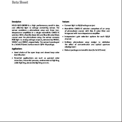
Light Sensor Hdjd-s822 5o4c25
October 2022 0
Po188 Ambient Light Sensor h651t
July 2020 6
Light Detecting Sensor Project Report 4se6o
December 2021 0
Light Sensor Using Photo Diode 686j2j
November 2019 47
Laporan Praktikum Sensor 2 k63h
October 2020 0More Documents from "dev aditya" 255t3c
Light Sensor 2 42rx
November 2022 0
258570048 Bollywood Museum j35p
December 2019 29
6l6m1j
December 2019 163
6l6m1j
January 2022 0
Conversations With The Greatest Networker In The World .pdf 505vd
November 2019 240