Mega Kabel Catalog Full 1w4b1s
This document was ed by and they confirmed that they have the permission to share it. If you are author or own the copyright of this book, please report to us by using this report form. Report 3b7i
Overview 3e4r5l
& View Mega Kabel Catalog Full as PDF for free.
More details w3441
- Words: 6,838
- Pages: 27
Page
^J'h 55/t, ME,C,{ merL
o PVC
/I/SULATED CABLES
CONSTRUCTION CONDUCTOR
INSULATION COLOUR OF INSULATION SHEATH COLOUR OF CORES
COLOUR OF SHEATH
PLAIN ANNEALED COPPER CONDUCTOR PVC RED, YELLOW BLUE, GREEN, BLACKAND WHITE PVC RED OR BLACK, OTHER COLOURS SINGLE-CORE UPON REQUEST REDAND BLACK TWIN-CORE THREE-CORE RED, YELLOWAND BLUE FOUR.CORE RED, YELLOW BLUEAND BLACK BLACIVWHITE/R ED
PVG-I NSU LATED, NON-SHEATHED GABLES.
450 /,750 VOLTS MAXIMUM CONDUCTOR TEMPERATURE: 70 OC Max. Conductor Resistance at 20"C Cross Sectional
Insulation
Approx. Overall
Minimum Insulation
Approx.
Diameter (Upper Limit)
Plain Annealed Copper
Resistance at 70 "C
Weight Per 100 Meter
mm
mm
Q/Km
MQ/Km
Kg
0.1
3.3
12.r0
0.0110
2.r
0.7
3.5
t2.10
0.0100
2.r
0.8
3.9
7
.4r
0.0100
3.3
0.8
4.2
7
.4r
0.0090
3.2
4
0.8
4.8
4.6r
0.0077
4.9
6
0.8
5.4
3.08
0.0065
6.9
10
1.0
6.8
I .83
0.0065
11.6
T6
1.0
8.0
1.15
0.0050
n.9
25
t.2
9.8
0.727
0.0050
28.0
35
t.2
11.0
0.524
0.0040
37 .5
50
r.4
13.0
0.3 87
0.0045
s0.5
70
1,4
15.0
0.268
0.0035
7 1.5
95
r.6
r7 .0
0.193
0.003s
98.5
Area of Conductor
Thickness
mmt 1.5
I
.5
ii
'i
,
"^'11,1
2.5
2.5
" "r
r.tl..fll . ;J
'trJ.
r20
1.6
r
9.0
0.153
0.0032
t22.0
150
1.8
2r.0
0.r24
0.0032
150.5
r85
2.0
23.5
0.0991
0.0032
188.5
240
2.2
26.5
0.07 54
0.0032
246.0
300
2.4
29.s
0.060 r
0.0030
307 .5
400
2.6
33.5
0.0470
0.0028
39
r.5
500
2.8
37.0
0.0366
0.0028
499.2
630
2.8
4r.0
0.0283
0.0025
* r.25
0.7
3.5
14.6
0.0r 10
634.3 2.0
* Product produce according to Mega Kabel specification.
Notes :
Current rating and voltage drop refer to Page A-
1
1
o
.J'h
Page 2
MEcA
5*F.trL
O
PVC /I/SULATED CABLES
PVG-I NSULATED, PVG-SH EATH ED GABLES.
300 / 500
vours
MAXIMUM CONDUCTOR TEMPERATURE: 70 OC Approx. Overall Diameter Cross Sectional
Insulation
Area of Conductor
Thickness
mmt
mm
Sheath Thickness
Max. Conductor Resistance at 20 "C
Lower
Upper
Limit
Limit
mm
mm
mm
Approx.
Weight Per
Resistance at70 "C
Q/Km
MQ/Km
Kg
100
Meter
1.5
0.7
0.8
4.2
4.9
12.r0
0.0110
3.6
1.5
0.7
0.8
4.3
5.0
t2.10
0.0100
3.5
2.5
0.8
0.8
4.8
5.8
1
.4r
0.0 100
4.8
2.5
0.8
0.8
5.0
6.0
7
.4r
0.0090
4.1
4
0.8
0.9
5.4
6.8
4.61
0.0071
7.1
6
0.8
0.9
6.0
1.4
3.08
0.0065
9.4
10
1.0
0.9
7.2
8.8
I .83
0.0065
t4.5
r6
1.0
1.0
8.4
r
0.5
1.15
0.00s2
22.0
25
r.2
l.l
r
12.5
0.127
0.0050
32.1
r 3.5
0.524
0.0044
43.4
5.1
14.6
0.01 10
3.3
0.0
r.2 l.l I 1.0 * 1.25 0.7 0.8 4.3 * Product produce according to Mega Kabel specification. 35
600/1000 Nominal
Insulation
Sheath
Area
Thickness
Thickness
of Conductor
Notes
Minimum
Insulation
Plain Annealed Copper
Approx. Overall
vours Approx.
Diameter
Cable Weight
mm
Kg/km
mm'
mm
mm
50
r.4
r.4
15.
l
592
70
t.4
r.4
16.9
808
95
1.6
1.5
t9.4
I 100
120
1.6
1.5
2r.0
I
353
150
1.8
r.6
23.2
1658
r85
2.0
1.7
25.8
2065
240
2.2
1.8
29.0
268r
300
2.4
r.9
32.1
333s
400
2.6
2.0
35.8
42t9
500
2.8
2.r
39.6
5268
630
2.8
2.2
43.8
668 I
Current rating and voltage drop refer to Page A- I
o
Page 3
^a"h
5/t+, ME,CA ,sB*rF
. PVC /I/SULATED CABLES
PVG-I NSU LATED, PVG-SH EATH ED GABLES.
300/500 voriTs oC
MAXIMUM CONDUCTOR TEMPERATURE z 70 Approx. Overall Diameter Cross Sectional
Insulation
Area of Conductor
Thickness
Sheath Thickness
Max. Conductor Resistance at
Lower
Upper
Limit
Limit
20'C Minimum
Approx.
Insulation
Weight Per
Plain Annealed Copper
Tinned Annealed Copper
Resistance at 70 "C
Q/I(m
MQ/Km
Kg
100
Meter
mm'
mm
mm
mm
mm
Q/Km
1.5
0.7'
r.2
7.6
10.0
12.r0
12.20
0.0110
10.3
1.5
0,7
r.2
7.8
r0.2
12.IO
12.20
0.0100
t0.4
2.5
0.8
1,2
8.8
11.5
I .41
7
.56
0.0100
14.4
2.5
0.8
1,2
9.2
t2.0
7
7
.56
0.0090
14.l
4
0.8
1,2
9.7
12.5
4.6r
4.70
0.0085
19.6
6
0.8
1,2
r0.l
14.0
3.08
3.1r
0.0065
25.4
10
1.0
t.4
13.8
t7 .5
1.83
1.84
0.0065
4r.3
2.5 x 2C (Flat Twin)
0.8
1.0
5.4 x 8.9
0.0100
l 1.0
6.4
x I 1.5
7
.4r
.4r
600nooo vot,Ts Nominal
Approx.
Thickness
Thickness
Area
Shape
of
of
Approx. Overall
of Conductor
of Conductor
Insulation
Sheath
Diameter
Cable Weight
mm
mm
mm
Kg/km
mmt T6
C.C.
1.0
1.8
18.6
601
25
S.S.
1.2
1.8
18.4
880
25
C.C.
1.2
1.8
22.1
923
35
S.S.
1.2
1.8
20.r
920
50
S.S.
r.4
1.8
22.8
t220
70
S.S.
1,4
1.9
25.5
1670
95
S.S.
r.6
2.0
29.3
2270
t20
S.S.
1.6
2.r
31.8
2800
150
S.S.
1.8
2.2
35. I
34r0
185
S.S.
2.0
2.4
39.1
4210
240
S.S.
2.2
2.5
43.9
5560
300
S.S.
2.4
2.7
48.7
6930
400
S.S.
2.6
2.9
54.2
8770
Colours for core identification: red and black.
Black sheath.
Shape
Notes
:
:
C.C. C.S. S.S.
: : :
Circular Compacted Stranded Conductor (Class 2). Circular Stranded Conductor (Class 2). Shaped Stranded Conductor (Class 2). Current rating and voltage drop refer to Page A- 3
O
Page 4
^JA
5/t, MtrGA 5*u_T?1,
O
PVC /I/SULATED CABLES
PVG-I NSULATED, PVG-SHEATHED GABLES.
300 1500 vours MAXIMUM CONDUCTOR TEMPERATURE: 70 OC Cross Sectional
Insulation
Area of Conductor
Thickness
Sheath Thickness
Approx. Overall
Max. Conductor
Diameter
Resistance at 20 oC
Lower
Upper
Limit
Limit
Minimum
Approx.
Insulation
Weight Per
Plain Annealed Copper
Tinned Annealed Copper
Resistance at 70 "C
Meter
100
mmt
mm
mm
mm
mm
Q/Km
O/Km
MC)/Km
Kg
1.5
0.1
r.2
8.0
10.5
12.l
t2.2
0.01 10
12.3
1.5
0.1
1.2
8.3
r
0.8
L2.l
12.2
0.0100
I
2.5
0.8
t.2
9.2
t2.0
7 .41
L56
0.0100
17
2.5
0.8
t.2
9.8
t2.6
7
.56
0.0090
t7 .2
4
0.8
t.2
r0.2
13.0
4.61
4.70
0.008s
24.0
6
0.8
1.4
II.7
r
5.5
3.08
3.11
0.006s
32.0
t0
1.0
1.4
t4.3
19.0
.83
I .84
0.0065
52.4
r
.4r
7
60011000 vol;Ts Nominal Area
Shape
of Conductor
of Conductor
mmt
Thickness
of Insulation
of
Approx. Overall
Sheath
Diameter
Cable Weight
mm
mm
mm
Kg/km
t6
C.C.
1.0
r.8
19.1
750
25
S.S.
t.2
1.8
20.4
l 069
25
C.C.
1.2
r.8
23.5
l 090
35
S.S.
t.2
1.8
22.4
l 360
50
S.S.
t.4
1.8
25.5
l8 10
70
S.S.
t.4
1.9
28.7
2480
95
S.S.
T,6
2.1
3
3.3
3390
r20
S.S.
t.6
2.2
36.3
4180
150
S.S.
1.8
2.3
40.0
5r
185
S.S.
2.0
2.5
44.6
64r0
240
S.S.
2.2
2.6
50. r
8 150
S.S.
2.4
2.8
55.6
10 140
400
S.S.
2.6
3.1
62.2
t2860
Black sheath.
Notes
l0
300
Colours for core identification: red. yellow and blue.
Shape
Approx.
Thickness
:
:
C.C. C.S. S.S.
: : :
Circular Compacted Stranded Conductor (Class 2). Circular Stranded Conductor (Class 2). Shaped Stranded Conductor (Class 2). Cunent rating and voltage drop refer to Page A-3
3.0 .4
O
.Jh
55/t, ME,CA _ry*u_Ft-
O
PVC /I/SLILATED CABLES
PVG-INSULATED, PVG.SHEATHED GABLES.
300 / 500 vouTs MAXIMUM CONDUCTOR TEMPERATURE: 70 OC Approx. Overall
Max. Conductor
Diameter
Cross Sectional
Insulation
Area of Conductor
Thickness
Sheath Thickness
Resistance at
Lower
Upper
Plain
Limit
Limit
Annealed
20'C Minimum
Approx.
Insulation
Weight Per
Copper
Tinned Annealed Copper
Resistance at70 "C
Meter
100
mm
mm
f)/Km
Q/Km
MC'/Krn
1.2
8.8
I1.5
0.0110
I
9.r
11.8
t2.l t2.l
12.20
t.2
12.20
0.0100
15.3
1.2
t0.2
r
.41
t .56
0.0 r 00
2r.4
0.8
t.2
10.8
l 3.6
7 .41
7
.56
0.0090
2r.5
0.8
t.4
n.2
r4.5
4.6r
4.10
0.0085
3 1.0
6
0.8
1.4
12.8
n.0
3.08
3.1l
0.0065
4t.0
l0
1.0
1.4
I
5.8
20.5
r .83
1.84
0.006s
66.0
mmt
mm
mm
1.5
0.7
1.5
0.7
2.5
0.8
2.5
4
3.0
7
Kg
600/1000 voLTs Nominal Area
Shape
of Conductor
of Conductor
mmt
Thickness
Thickness
of Insulation
of
Approx. Overall
Sheath
Diameter
Cable Weight
mm
mm
mm
Kg/km
l6
C.C.
1.0
r.8
2t.6
960
25
S.S.
1.2
1.8
22.9
1381
25
C.C.
1.2
1.8
25.9
r 400
35
S.S.
t.2
1.8
25.4
I 808
50
S.S.
1.4
r.9
29.2
2450
70
S.S.
T,4
2.0
33.0
3
95
S.S.
1.6
2.2
3
8.3
45 80
S.S.
1.6
2.3
41.8
5630
150
S.S.
1.8
2.5
46.3
6920
r85
S.S.
2.0
2.6
5 1.3
8640
240
S.S.
2.2
2.8
5
8.0
t1290
300
S.S.
2.4
3.1
64.6
r4095
400
S.S.
2.6
3.3
72.0
r
Black sheath.
Notes
350
120
Colours for core identification: red. vellow. blue and black.
Shape
Approx.
:
:
C.C. C.S. S.S.
: : :
Circular Compacted Stranded Conductor (Class 2). Circular Stranded Conductor (Class 2). Shaped Stranded Conductor (Class 2). Current rating and voltage drop refer to Page A- 3
7860
5.0
o
.a"h 5/,+, MEGA
Page 6
o
-5*F,trI-,
PVC INSULATED, PVC SHEATHED ARMOURED CABLES
CONSTRUCTION CONDUCTOR
INSULATION BEDDING ARMOUR SHEATH COLOUR OF CORES
COLOUR OF SHEATH
:
PLAIN ANNEALED COPPER CONDUCTOR PVC PVC GALVANISED STEELWIRES PVC RED AND BLACK TWIN-CORE RED, YELLOW AND BLUE THREE.CORE RED. YELLOW. BLUEAND BLACK FOUR-CORE BLACK
PVG-I NSU LATED, PVC-SH EATH
E
D ARM
OU
600 /
RED GABLES.
{ooo voLTs Extruded Bedding
Nominal Area
Shape
of Conductor
of Conductor
Thickness
Thickness
Nominal
Thickness
of Extruded
armour
of
Approx. Overall
Approx.
of Insulation
Oversheath
Diameter
wt.
Bedding
wire diameter
mm
mm
mm
mm
mm
Kg/km
mmt
Cable
1.5
C.S.
0.6
0.8
0.9
r.3
tI.7
279
1.5
C.C.
0.6
0.8
0.9
r.4
12.3
300
2.5
C.S.
0.1
0.8
0.9
r.4
l3.l
347
2.5
C.C.
0.7
0.8
0.9
t.4
r
3.6
349
4
C.C.
0.8
0.8
0.9
1.4
15.
I
434
6
C.C.
0.8
0.8
0.9
1.5
16.5
520 800
10
C.C.
1.0
0.8
r.25
1.6
20.r
r6
C.C.
1.0
0.8
r.25
1.6
21.9
960
25
S.S.
r.2
1.0
1.6
r.l
23
1435
25
C.C.
1.2
1.0
1.6
t.7
26.1
r435
35
S.S.
r.2
1.0
1.6
1.8
24.9
r
50
S.S.
t.4
1.0
1.6
t.9
27.8
2100
70
S.S.
1.4
1.0
1.6
r.9
30.4
2640
680
95
S.S.
1.6
1.2
2.0
2.1
35.5
3680
t20
S.S.
t.6
1.2
2.0
2.2
3
8.0
43r0
150
S.S.
1.8
r.2
2.0
2.3
4r.3
5060
r85
S.S.
2.0
r.4
2.s
2.4
46.4
6570
240
S.S.
2.2
t.4
2.5
2.5
5r.2
8110
300
S.S.
2.4
r.6
2.5
2.7
56.4
9190
400
S.S.
2.6
1.6
2.5
2.9
6r.9
1r850
Colours for core identification: red and black.
Black sheath.
Shape : Notes :
C.C. C.S. S.S.
: : :
Circular Compacted Stranded Conductor (Class 2). Circular Stranded Conductor (Class 2). Shaped Stranded Conductor (Class 2). Current rating and voltage drop refer to Page A-5
o
.J"k
5/1, Mtrc,A.. -_5,+u_FL
o
PVC INSUIATED, PVC SHEATHED ARMOARED CABLES
PVG-I NSU LATE D, PVG-SH EATH
ED
AMOURED CABLES.
600
t{ooo volTs Extruded Bedding
Nominal Area
Shape
of Conductor
of Conductor
mmt
Thickness
Thickness
Nominal
Thickness
of Extruded
armour
of
Approx. Overall
Approx.
of
Oversheath
Diameter
wt.
Bedding
wire diameter
mm
mm
mm
mm
mm
Kg/km
Insulation
Cable
1.5
C.S.
0.6
0.8
0.9
1.4
12.3
32r
1.5
C.C.
0.6
0.8
0.9
r.4
12.8
3t9
2.5
C.S.
0.1
0.8
0.9
t.4
13.6
402
2.5
C.C.
0.7
0.8
0.9
T,4
t4.l
392
4
C.C.
0.8
0.8
0.9
r.4
l 5.8
485
6
C.C.
0.8
0.8
r.25
1.5
18.0
690
l0
C.C.
1.0
0.8
t.25
r.6
2r.2
920
r6
C.C.
1.0
0.8
r.25
T,6
23.r
r200
25
S.S.
1.2
1.0
t.6
t.7
25.0
177
25
C.C.
t.2
1.0
1,6
t.7
28.2
1843
35
S.S.
1.2
1.0
r.6
1.8
27.3
2230
50
S.S.
1.4
1.0
1.6
r.9
30.5
28r8
l0
S.S.
t.4
t.2
2.0
2.0
35.0
3900
95
S.S.
t.6
t.2
2.0
2,7
39.3
4990
t20
S.S.
t.6
T,2
2.0
2.2
42.2
59 10
r50
S.S.
1.8
t.4
2.5
2.4
47 .5
7
185
S.S.
2.0
r.4
2.5
2.5
5
r.9
9060
240
S.S.
2.2
r.6
2.5
2.6
57.8
11410
300
S.S.
2.4
1.6
2.5
2.8
63.2
r 3780
69.6
r6232
S.S.
2.6
1.6
2.5
Colours for core identification: red, vellow and blue.
Black sheath.
Shape : Notes
:
: : :
Circular Compacted Stranded Conductor (Class2). Circular Stranded Conductor (Class 2). S.S. Shaped Stranded Conductor (Class 2). Current rating and voltage drop refer to Page A-5 C.C. C.S.
3.0
0
530
O
^a^h
5/t, MEcA -*P.flr
o
PVC INSUIATED, PVC SHEATHED ARMOURED CABLES
pvG-tNsuLATED, PVG-SHEATHED ARMOURED CABLES. 600 /
{ooo volTs Extruded Bedding
Nominal Area
Shape
of Conductor
of Conductor
mmt
Thickness
Thickness
Nominal
Thickness
of Extruded
armour
of
Approx. Overall
Approx.
of
Oversheath
Diameter
wt.
Bedding
wire diameter
mm
mm
mm
mm
mm
Kg/km
Insulation
Cable
1.5
C.S.
0.6
0.8
0.90
r.4
l 3.0
357
1.5
C.C.
0.6
0.8
0.90
r.4
l 3.5
357
2.5
C.S.
0.1
0.8
0.90
t.4
t4.5
447
2.5
C.C.
0.1
0.8
0.90
1.4
r 5.0
450
4
C.C.
0.8
0.8
l .25
1.5
17.8
670
6
C.C.
0.8
0.8
r.25
1.5
t9.2
170
t0
C.C.
1.0
0.8
1.25
1.6
22.8
I
083
I6
C.C.
1.0
1.0
r.60
r.7
26.3
1587
25
S.S.
t.2
1.0
r.60
1.8
21 .8
2r88
25
C.C.
t.2
1.0
1.60
1.8
30.7
2t54
3s
S.S.
t.2
1.0
1.60
1,9
30.5
2139
50
S.S.
t.4
t.2
2.00
2.0
35.4
31
l0
S.S.
1,4
1.2
2.00
2.1
39.2
4198
95
S.S.
r.6
t.2
2.00
2.2
44.3
6n4
r20
S.S.
1.6
r.4
2.50
2.4
49.3
197 6
46
9630
150
S.S.
r.8
r.4
2.50
2.5
5
185
S.S.
2.0
r.6
2.50
2.6
59.0
n392
240
S.S.
2.2
r.6
2.50
2.8
65.7
t44r4
300
S.S.
2.4
r.6
2.50
3.0
72.0
ll
81.3
21467
400
S.S.
2.6
1.8
Colours for core identification: red, yellow, blue and black.
Black sheath.
Shape Notes
:
:
C.C. C.S. S.S.
: : :
Circular Compacted Stranded Conductor (Class 2). Circular Stranded Conductor (Class 2). Shaped Stranded Conductor (Class 2). Current rating and voltage drop refer to Page A-5
3.15
3.3
3.6
502
O
Page 9
^J'h
55/t+, ME,CA
.-5*B_FL
O
PVC INSULATED. PVC SHEATHED ARMOURED AUXILIARY CABLES
CONSTRUCTION PLAIN ANNEALED COPPER CONDUCTOR
CONDUCTOR INSTJLATION
BEDDING
PVC PVC
ARMOTJR
GALVANISED STEEL WIRES
SHEATH
PVC
COLOUR OF CORES COLOUR OF SHEATH
WHITE WITH BLACK NUMBERING BLACK
PVC-|NSULATED, PVG-SHEATHED ARMOURED AUXTLIARY CABLES.
600
t{ooo volTs Extruded Bedding
Number
Nominal
Thickness
Thickness
Nominal
Thickness
Approx.
Approx.
of
Area
of
armour
of
of Conductor
Insulation
wire diameter
Oversheath
Overall Diameter
Cable
cores
of Extruded Bedding
n
mmt
mm
mm
mm
mm
mm
kg/km
0.8
0.90
4.3
453
0.8
0.rx)
15.2
525
0.8
r
.25
19.0
815
0.8
125
t9.4
819
5
r0 t2
1.5
0.6
|
wt.
I4l
l9
0.8
l .25
22.2
I
27
1.0
I .6t)
26.7
168 I
37
1.0
1.60
29.2
2042
-18
1.0
1.60
32.9
247 6
5
0.8
0.90
16.3
603
l
0.8
1.25
l 8.0
854
l0
0.8
1.25
2r.9
I
ll
043
0.8
t.25
22.4
TT4I
l9
1.0
1.60
26.6
l7l0
27
r.0
1.60
30.7
2t99
3l
1.0
1.60
34.0
27
.+8
t.2
2.00
39.5
3689
2.5
0.7
tl
o
Page 10
^a.h
5/+, ME,GA
o
mBr;,Ek
XLPE INSAI-ATED, PVC SHEATHED CABLES
CONSTRUCTION PLAIN ANNEALED COPPER CONDTJCTOR XLPE (CROSS-LTNKED POLYETHYLENE) RATED 900C
CONDUCTOR
INSULATION SHEATH COLOUR OF CORES
PVC
SINGLE-CORE
TWIN-CORE THREE-CORE COLOUR OF SHEATH
:
FOUR-CORE
: : : :
NATTJRAL. RED OR BLACK. OTHER COLOURS UPON REQUEST RED AND BLACK
RED. YELLOWAND BLUE RED. YELLOW BLUEAND BLACK
BLACK
XLPE TNSULATED, PVC-SHEATHED GABLES.
600 / Cross Sectional
Area of Conductor
Shape
Thickness
Approx. Overall
Approx.
Diameter
Cable Weight
mm
mm
mm
Kg/km
2r0
I6
C.C.
0.7
l.-t
9.1
25
C.C.
0.9
I.-t
I 1.0
310
35
C.C.
0.9
I .-l
t2.3
410
50
C.C.
1.0
l
13.1
540
.-1
l0
C.C.
l.l
r.1
15.1
750
95
C.C.
1.1
1.5
l 7.8
l 020
t20
C.C.
t.2
1.5
19.1
1260
150
C.C.
t.4
1.6
21.9
l 560
185
C.C.
1.6
1.6
24.1
r920
240
C.C.
t.7
1.7
27
.l
2470
300
C.C.
1.8
1.8
30.5
3090
400
C.C.
2.0
1.9
3
3.5
40r0
500
C.C.
2.2
2.0
37 .4
5035
2.4
'))
42.0
6500
630
Shape
Sheath
Thickness
of Conductor
mmt
Notes
Insulation
{ooo voLTs
C.C.
C.C. : Circular Compacted Stranded Conductor (Class 2). Current rating and voltage drop refer to Page A-2
o
Page
^a'h
5/4t MEGA
. XLPE INSAI-ATED, PVC SHEATHED CABLES
.,5*8..trL
xLpE INSULATED, PVG SHEATHED GABLES.
1[ffi,'l I
GOO Cross Sectional
Area of Conductor
Shape
of Conductor
mmt
Insulation
Sheath
Thickness
Thickness
Cable Weight
Kg/km
mm
mm
r.5
C.S.
0.7
1.8
10.5
r20
2.5
C.S.
0.7
1.8
11.5
150
4
C.S.
0.7
1.8
12.5
195
6
C.C.
o.7
1.8
13.5
250
10
C.C.
0.7
1.8
1
5.5
355
l6
C.C.
0.7
1.8
17 .4
475
25
S.S.
0.9
r.8
r7 .6
635
35
S.S.
0.9
1.8
18.5
835
50
S.S.
1.0
1.8
2r.0
tI20
70
S.S.
1.1
1.8
23.5
r545
95
S.S.
1.1
r.9
26.5
2070
r20
S.S.
t.2
2.0
29.0
2580
150
S.S.
r.4
2.2
32.5
3200
185
S.S.
r.6
2.3
35.5
3955
240
S.S.
r.7
2.5
39.s
5 150
300
S.S.
r.8
2.6
44.0
6470
400
S.S.
2.0
2.9
50.0
8 150
Black sheath.
Notes
Approx.
Diameter mm
Colours for core identification: red and black.
Shape
Approx. Overall
:
:
C.S. C.C. S.S.
: : :
Circular Stranded Conductor (Class 2). Circular Compacted Stranded Conductor (Class 2). Shaped Stranded Conductor (Class 2). Current rating and voltage drop refer to Page A-4
1 1
o
.a"k 5/,+, ME,GA
Page 12
MPIFI.
o
XLPE INSULATED, PVC SHEATHED CABLES.
XLPE TNSULATED, pVG SHEATHED GABLES.
600 / Cross Sectional
Area of Conductor
Shape
of Conductor
mmt
Insulation
Sheath
Thickness
Thickness
Approx.
Diameter
Cable Weight
mm
mm
Kg/km
1.5
C.S.
0.7
1.8
I 1.5
r49
2.5
C.S.
0.1
1.8
12.0
185
4
C.S.
0.7
1.8
I
3.0
240
6
C.C.
0.7
1.8
r4.5
315
10
C.C.
0.7
1.8
16.5
465
I6
C.C.
0.7
r.8
18.0
645
25
C.C.
0.9
1.8
20.6
905
35
S.S.
0.9
1.8
21.3
12r0
50
S.S.
1.0
r.8
24.0
r
70
S.S.
95
600
1.9
27 .5
2260
S.S.
l.l l.l
2.0
31.0
3030
r20
S.S.
1.2
2.1
34.0
3875
150
S.S.
t.4
2.3
39.r
4700
r85
S.S.
1.6
2.4
41.5
58 10
240
S.S.
r.7
2.6
47 .0
7
300
S.S.
1.8
2.8
5 1.0
93s0
400
S.S.
2.0
3.0
57 .5
I
Black sheath.
Notes
Approx. Overall
mm
Colours for core identification: red, yellow and blue.
Shape
{ooo volTs
C.S. C.C. S.S.
: : :
Circular Stranded Conductor (Class 2).
Circular Compacted Stranded Conductor (Class 2). Shaped Stranded Conductor (Class 2). Current rating and voltage drop refer to Page A-4
570
2000
Page 13
^a"h 5/*, MEGA ,*B,.PI.
o
XLPE INSULATED, PVC SHEATHED CABLES
XLPE INSULATED, PVG SHEATHED GABLES.
600 / Cross Sectional
Area of Conductor
Shape
of Conductor
mm'
Insulation
Sheath
Thickness
Thickness
Approx.
Diameter
Cable Weight
mm
mm
Kg/km 175
1.5
C.S.
0.7
1.8
12.5
2.5
C.S.
0.7
r.8
13.5
220
4
C.S.
0.7
1.8
14.5
300
6
C.C.
0,7
1.8
16.0
395
10
C.C.
0.7
1.8
r7 .5
580
I6
C.C.
0.7
1.8
19.5
840
25
C.C.
0.9
1.8
22.9
r200
35
S.S.
0.9
1.8
24.r
r592
50
S.S.
1.0
1.9
27.0
2r00
70
S.S.
1.1
2.0
3r.2
3012
95
S.S.
1.1
2.r
35.0
4050
t20
S.S.
t.2
2.3
3
8.0
5020
r50
S.S.
r.4
2.4
42.5
6020
I0
r85
S.S.
1.6
2.6
48.0
17
240
S.S.
1.7
2.8
54.r
10050
300
S.S.
1.8
3.0
6r.6
r2400
400
S.S.
2.0
3.3
67.0
16100
Black sheath.
Notes
Approx. Overall
mm
Colours for core identification: red, yellow, blue and black
Shape
{ooo vouTs
:
Circular Compacted Stranded Conductor (Class2). Shaped Stranded Conductor (Class 2). Current rating and voltage drop refer to Page A-4
S.S.
:
Circular Stranded Conductor (Class 2).
C.S. C.C.
:
o
.J'h
Page 14
5/+, MEGA HF,.rI.
o
XLPE INSALATED, PVC SHEATHED ARMOARED CABLES
CONSTRUCTION CONDUCTOR
INSULATION BEDDING ARMOUR SHEATH COLOUR OF CORES
COLOUR OF SHEATH
PLAIN ANNEALED COPPER CONDUCTOR xLpE (cRoss-LTNKED poLyETHyLENE) RATE 900C PVC GALVANISED STEELWIRES PVC TWIN-CORE : RED AND BLACK THREE-CORE : RED, YELLOWAND BLUE FOUR-CORE : RED, YELLOW BLUE AND BLACK BLACK
XLPE TNSULATED, PVG SHEATHED ARMOURED GABLES.
600 / Cross Sectional
Area of Conductor
Shape
of Conductor
mmt
Insulation
Nominal
Sheath
Thickness
diameter of
Thickness
steel wire
Approx.
Diameter
Cable Weight
Kg/km
mm
mm
mm
1.5
C.S.
0.7
0.9
1.8
t4.5
345
2.5
C.S.
0.7
0.9
1.8
r
5.5
390
4
C.S.
0.1
0.9
1.8
16.5
450
6
C.C.
0.7
0.9
1.8
18.0
530
10
C.C.
0.7
0.9
1.8
19.5
675
I6
C.C.
0.7
0.9
1.8
2r.5
800
25
S.S.
0.9
T,6
1.8
22.5
r230 1480
35
S.S.
0.9
r.6
1.8
24.0
50
S.S.
1.0
r.6
1.8
26.5
l 840
70
S.S.
l.l
t.6
2.0
29.5
2450
95
S.S.
1.1
2.0
2.1
3
3.0
32r0
r20
S.S.
1,2
2.0
2.2
36.0
3
150
S.S.
r.4
2.0
2.3
39.5
4650
185
S.S.
r.6
2.5
2.5
44.0
5880
240
S.S.
t.7
2.5
2.7
48.0
1260
2.8
52.5
8t 40
8.5
I 1405
300
S.S.
1.8
2.5
400
S.S.
2.0
2.5
Black sheath.
Notes
Approx. Overall
mm
Colours for core identification: red and black.
Shape
{ooo vol.Ts
:
:
C.S. C.C. S.S
: : :
Circular Stranded Conductor (Class 2).
Circular Compacted Stranded Conductor (Class 2). Shaped Stranded Conductor (Class 2). Current rating and voltage drop refer to Page ,{-6
3.1
5
850
o
Page 15
^a^k
5/t+ MEGA $t",Et
o
XLPE INSULATED, PVC SHEATHED ARMOURED CABLES
XLPE TNSULATED, PVG SHEATHED ARMOURED GABLES.
600 / {ooo Cross Sectional
Area of Conductor
Shape
of Conductor
mmt
Insulation
Nominal
Sheath
Thickness
diameter of
Thickness
steel wire
Approx.
Diameter
Cable Weight
mm
mm
mm
Kg/km
1.5
C.S.
0.7
0.9
r.8
15.5
380
2.5
C.S.
0.7
0.9
1.8
16.0
430
4
C.S.
0.7
0.9
1.8
r7 .5
515
6
C.C.
0.7
0.9
1.8
18.5
610
10
C.C.
0.7
0.9
1.8
20.0
190
I6
C.C.
0.7
0.9
1.8
22.0
1030
25
C.C.
0.9
r.6
1.8
26.0
t670
35
S.S.
0.9
1.6
1.8
26.5
I
930
50
S.S.
1.0
1.6
1.8
29.5
2450
70
S.S.
1.1
2.0
2.0
34.0
3440
95
S.S.
t.l
2.0
2.2
37 .5
4380
r20
S.S.
1.2
2.0
2.3
40.0
5450
150
S.S.
r.4
2.5
2.5
45.0
6680
185
S.S.
1.6
2.5
2.6
49.5
8050
240
S.S.
r.7
2.5
2.8
55.0
l0l
300
S.S.
1.8
2.5
3.0
59.5
r2t50
400
S.S.
2.0
2.5
3.2
66.s
Black sheath.
Notes
Approx. Overall
mm
Colours for core identification: red, yellow and blue.
Shape
volTs
C.S. C.C. S.S.
: : :
Circular Stranded Conductor (Class 2).
Circular Compacted Stranded Conductor (Class 2). Shaped Stranded Conductor (Class 2). Current rating and voltage drop refer to Page 4.-6
1
80
5540
o
.a'h
Page 16
5/#, MEGA o
5fT',-:L
XLPE INSULATED, PVC SHEATHED ARMOURED CABLES
xLPE-l NSU LATED, PVG-SH EATH E D ARMOURED GABLES.
600 t{ooo Cross Sectional
Insulation
Area of Conductor
Shape
of Conductor
Thickness
mm'
Nominal diameter of
mm
mm
Approx. Cable Weight
mm
mm
Kg/km
1.5
C.S.
0.7
0.9
1.8
16.0
420
2.5
C.S.
0.7
0.9
1.8
t7 .0
485
4
C.S.
0.7
0.9
1.8
r
8.5
590
19.5
715
6
C.C.
0.7
0.9
1.8
10
C.C.
0.7
0.9
1.8
2t.5
940
T6
C.C.
0.7
1.6
1.8
24.5
I
25
C.C.
0.9
1.6
1.8
28.0
t957
1,6
t.9
29.5
2400
480
35
S.S.
0.9
50
S.S.
1.0
r.6
2.0
32.5
3 160
70
S.S.
1.1
2.0
2.2
38.0
4320
95
S.S.
1.1
2.0
2.3
4t.0
5500
2.5
2.5
46.0
7120
r20
S.S.
1.2
150
S.S.
r.4
2.5
2.6
5 1.0
185
S.S.
r.6
2.5
2.8
s
8.0
l 0400
240
S.S.
L.l
2.5
3.0
64.0
13 100
300
S.S.
1.8
2.5
3.2
68.0
15800
400
S.S.
2.0
3.2
3.5
t7 .0
2IT2O
Black sheath.
Notes
Approx. Overall Diameter
steel wire
Colours for core identification: red. vellow blue and black.
Shape
Sheath
Thickness
vours
C.S. C.C. S.S.
: : :
Circular Stranded Conductor (Class 2). Circular Compacted Stranded Conductor (Class 2). Shaped Stranded Conductor (Class 2). Current rating and voltage drop refer to Page A-6
8550
o
.a'h
55/t, ME,CA 5,'+P.rI'
Page 17
. SINGLE CORE, XLPE INSULATED. PVC SHEATHED ARMO(IRED CABLES .
CONSTRUCTION CONDUCTOR
PLAIN ANNEALED COPPER CONDUCTOR
INSULATION
XLPE (CROSS-LINKED POLYETHYLENE) RATED 900C
BEDDNG
PVC
ARMOUR
HARD-DRAWN ALUMINIUM WIRE
SHEATH
PVC
:
COLOIJR OE SHEATH
BLACK
XLPE INSULATED, PVG-SHEATHED ARMOURED GABLES. 600 l{ooo volTs Extruded Bedding
Nominal
Thickness
Thickness
Nominal
Thickness
Area
Shape
of
armour
of
Approx. Overall
Approx.
of Insulation
Extruded
Oversheath
Diameter
wt.
of Conductor
of Conductor mm
Bedding mm
wire diameter mm
mm
mm
Kg/km
mmt
Cable
50
C.C.
1.0
1.0
t.25
1.8
19.0
750
70
C.C.
r.0
t.25
1.8
20.5
980
95
C.C.
l.l l.l
1.0
t.6
1.8
22.s
r270
t20
C.C.
t.2
1.0
t.6
1.8
24.0
I
150
C.C.
1.4
1.0
t.6
1.8
26.5
l 890
185
C.C.
1.6
1.0
1.6
1.8
28.5
2300
240
C.C.
1.7
1.0
1.6
1.9
32.5
2900
300
C.C.
r.8
1.0
r.6
1.9
34.s
3
4600
570
6s0
400
C.C.
2.0
t.2
2.0
2.r
39.s
500
C.C.
2.2
t.2
2.0
2.2
43.0
5700
630
C.C.
2.4
t.2
2.0
2.3
49.s
7
800
C.C.
2.6
1.4
2.5
2.5
55.0
9360
l 000
C.C.
2.8
1.4
2.5
2.7
6l .0
11600
Shape
C.C.
:
Notes
Current rating and voltage drop refer to Page A-l
Circular Compacted Stranded Conductor (Class 2).
400
SINGLE CORE PVC INSULATED CABLE SINGLE CORE PVC INSULATED PVC SHEATHED CABLE
VoLTAGE 300/500 V, 4501750V OR 600/1000V AMBIENT TEMPERATURE 3O"C CONDUCTOR OPERATING TEMPERATURE 7O"C
On Perforated Cable Tray
Enclosed In Gonduit or In Trunking Size of
Gonductor (
2 cables 1- phase
2 cables 1- phase ac or dc
mm')
(amp)
1.0 1.5
13.5
12
17.5
15.5
2.5
24
21
4
32
6
41
10 16
76
25
101
35 50 70
125
28 36 50 68 89 110
151
134
192 232
171 207
269 30q 341 400 458 546 626
150 185
240 300 400 500 630 800 1 000
ac, touching (amp)
(amp)
131 196
114 143 174
110 137 167
251 304
225 275
216 264
239
352
262 296
321 372
346 394
406 463 546 629
308 356 409 485
467
754
162
533
720
Trefoil
(amp)
(amp)
57
95 120
3 or 4 cables 3- phase
ac or dc flat and touching
427 507 587
689 789 905 1020 1149
868 005 1 086
611
1
'1216
561
656
749 855 971 1079
VOLTAGE DROP
Conductor (
3 or 4 cables 3 - phase ac
2 cables 1- phase ac
Size of
conduit
on cable tray, touching
Enclosed in conduit
flat and touching
on cable tray, trefoil
(Mv/A/m)
(Mv/A/m)
(Mv/A/m)
Enclosed in
on cable tray,
mm')
(Mv/A/m)
(Mv/A/m)
(Mv/A/m)
1.0 1.5
44
44
44
38
38
38
29
29
25
25
25
2.5
29 18
18
18
15
15
15
4
11
11
11
6 10
7.3 4.4 2.8 1.75 1.25 0.93 0.63 0.46 0.36 0.29 0.23 0.180 0.145 0.105 0.086 0.068 0.053
7.3 4.4
7.3 4.4 2.8 1.75 1.25 0.95 0.66 0.50
9.5 6.4 3.8 2.4 1.5s
9.5 6.4
9.5 6.4
16
25 35 50 70
95 120 150 185
240
2.8 1.80 1.30 1.00
0.72 0.56 0.47 0.41
0.37 0.33
300 0.31 400 0.29 500 0.28 630 0.27 800 1 000 0.042 Note : Gorrection factors for ambient temperature and
3.8
3.8
2.4 1.55
2.4 1.50 1.10 0.82 0.57 0.43 0.36 0.30 o.26 0.22 0.190
1.10
1.10
0.85
0.84 0.60 0.47 0.40 0.34
0.61
0.48
0.41
0.41
0.34 0.29 0.25 0.22 0.20 0.185
0.36 0.32 0.29 0.27 0.25
0.17 5
0.24
0.31
65
0.27 0.25 0.24 0.23 0.22 0.22
0.1 60
0.21
0.1
0.2s
group installation, please refer Page B-1
0.17 5
0.160 0.150 0.1 45 0.1 40
.a IM I'C;A SINGLE CORE XLPE INSULATED PVC 11
l\IiIrl
VOLTAGE 600/1OOO V AMBIENT TEMPERATURE 3O"C CONDUCTOR OPERATING TEMPERATURE gO"C
SHEATHED CABLE
Enclosed In Gonduit or ln Trunking Size of
2 cables 1-phase ac or dc
3 or 4 cables 3-phase ac
(amp)
(amp)
1.0
17
15
1.5 2.5 4
23
20 28
Gonductor (
mm')
42 54 75 100 133
10 16
25 35 s0 70 95 120 150 185
253
(amp)
117
161
141
144 175
200 242 310 377
176 216 279 342
135 169 207 268
437
400
312 342
783
584 666
504 575 679 783 940 1 083
900
764
1254
528
trefoil (amp)
222 269
306 354 393 449 603 683
touching
37
198
240
ac
ac or dc flat and touching
48 66 88
164
300 400 500 630 800 1 000
3 or 4 cables 3-phase
2 cables 1-phase
(amp)
31
6
On Perforated Cable Tray
384
4s0 514
1
358
1520
328 383
464
444
533 634
510 607
736
703 823
868 998 1151
1
1275 436
1214 1349
946 088
1
VOLTAGE DROP
Conductor (
mm')
( mv/A/m
)
Enclosed in conduit
on cable tray, touching
Enclosed in conduit
on cable tray, flat and touching
on cable tray trefoil
( mv/A/m
( mv/A/m
( mv/A/m
( mv/A/m
( mv/A/m
)
31
19 12
16 10
16 10
16 10
7.9 4.7 2.9 1.85 1.35 1.00
6.8 4.0 2.5 1.65 1.15 0.90 0.65
6.8 4.0 2.5 1.60 1.15 0.87 0.62
6.8 4.0 2.5 1.60 1.15 0.87
0.s0
0.46
o.42 0.37 0.32 0.29 0.27
0.38 0.32 0.28
0.45 0.37
0.185
0.25 0.24
0.17 5
0.23
0.195 0.180 0.170 0.165 0.165
46
1.5 2.5 4
31
31
19 12
19 12
6
7.9 4.7 2.9 1.85 1.35 0.99 0.68 0.49 0.39 0.32
7.9 4.7 2.9 1.90 1.35 1.05 0.75 0.58 0.48 0.43 0.37 0.33
240 300 400 500 630 800 1 000
0.072 0.056 0.04s
0.31
0.29 0.28 0.27
)
40 27
46
0.25 0.190 0.155 0.120 0.093
)
40 27
46
25 35 50 70 95 120 1s0 185
)
40 27
1.0
10 16
3 or 4 cables 3-phase ac
2 cables 1-phase ac
Size of
0.71
0,52 0.43 0.36 0.30
0.25 0.22 0.20
0.170 0.165
Note : Gorrection factors for ambient temperature and group installation, please refer Page B-l
0.24 0,21
0.61
0.31
0.26 o.22
0.195 0.175 0.160 0.150
0.145 0.140
)
.JL
55/{, MEcA Kn BtlI
-
PVC INSULATED PVC SHEATHED MULTI-CORE CABLE VoLTAGE 300/500V OR 600/1000 AMBIENT TEMPERATURE 3O"C
v
CONDUCTOR OPERATING TEMPERATURE 7O"C
On Perforated Gable Tray
Enclosed ln Conduit or ln Trunking Size of Gonductor
1 phase ac or dc
three or four-core cable 3 phase ac
1 phase ac or dc
three or four-core cable 3 phase ac
(amp)
(amp)
(amp)
(amp)
1.0
13
11.5
17
1.5
16.5 23 30 38 52 69 90 111 133 168
15
22 30 40
14.5 18.5 25 34 43 60 80 101
( mm')
2.5 4 6 10 16
25 35 50
70 95
120 150 185
240 300
400
two-core cable
two core cable
20 27 34 46 62 80 99 118
51
70 94 119
232 258 294 344 394 470
126 153 196
232 282 328 379 434 514
149 179 206 225 255
?o1
148 180
297 339
238
276 319
364 430 497 597
593
715
402
VOLTAGE DROP Gonductor cable,dG
Two-core cablen single-phase a.c
Thr€€- or four-Gore, three-phase a.c
( mv/A/m
( mv/A/m
( mv/A/m
Gross-
Two-core
section area ( mm')
)
)
38 25
1.0
44
44
1.5
29
29
2.5
18
18
15
4
11
11
6 10 16
7.3
7.3
9.5 6.4
4.4
4.4
3.8
2.8 1.75 1.25
2.9 1.75 1.25
2.4
0.93
0.94 0.65 0.50
0.81
o,41
0.35
0.34 o.29 0.24
0.29
o.21
0.185 0.160
25 35 50 70 95
120 150
18s 240 300
400
0.63
0.46 0.36 0.29 0.23
0.180 0.1 45 0.105
0.185
Note : Correction factors for ambient temperature and group installation, please refer Page B-1
1
.50
1.10 0.57 0.43
0.25 o.21
)
.JL
55fl{, M11
CA
K./\tlliI
-
XLPE INSULATED PVC SHEATHED MULTI-CORE CABLE VOLTAGE 600/1000 V AMBIENT TEMPERATURE 3O"C CONDUCTOR OPERATING TEMPERATURE gO"C
On Perforated Gable Tray
Enclosed In Gonduit or ln Trunking Size of Conductor (
mm')
1 phase ac or dc
three or four-core cable 3 phase ac
1 phase ac or dc
three or four-core cable 3 phase ac (amp)
two-core cable
two core cable
(amp)
(amp)
(amp)
1
17
21
18
1.5
26
23 32
4
22 30 40
15 19.5 26 35
6
51
44
10 16
69 91
25
119
60 80 105
35 50 70 95
146 175
2.5
120 150 185
240 300
400
36 49 63 86
265 305 334 384 459 532 625
54 75 100 127 158
115 149
128 154 194 233 268
221
42
185
192 246 298 346 399 456 538
225 289
352 410 473 542
300
340 398
641
455 536
741
621
865
741
VOLTAGE DROP Gonductor crosssection area (
mm')
Two-core cable,dG ( mv/A/m
)
Two-core cable, single-phase a.c ( mv/A/m
)
Thr€€- or four-Gore, three-phase a.c ( mv/A/m
1.0 1.5
46
46
31
31
40 27
2.5 4
19 12
19 12
16 10
6
7.9
7.9
6.8
4.7 2.9
4.7 2.9
4.O
.85 .35
1.90
1.65 1 .15
10 16
25 35 50 70 95
120 150 185
240
1 1
0.98 0.67 0.49 0.39 0.31
0.25 0.195
1.35 1
.00
0.69 0.52 o.42 0.35 o.29 0.24
300
0.1 55
o.21
400
o.120
0.190
Note : Gorrection factors for ambient temperature and group installation, please refer Page B-1
2.5
0.87 0.60 0.45 0.37 0.30 o.26 0.21
0.185 0.165
)
.-L
5tt Mtr(jA I\,,rI:T:I
-
PVC INSULATED PVC SHEATHED MULTI-CORE ARMOURED CABLE VOLTAGE 600/1 OOO V AMBIENT TEMPERATURE 3O'C GROUND TEMPERATURE 2O'C CONDUCTOR OPERATING TEMPERATURE 7O"C
Direct In Ground or ln Duct ln Ground
On Perforated Gable Tray Size of
l
Conductor
1 three or four-core
two- core cable
cable 3 phase ac
( mm')
(amp)
(amp)
(amp)
22 29 37 46 60 78 99 119
1.5
22
19
2.5
31
4
41
6 10 16
53 72 97
25 35 50 70 95
128
26 35 45 62 83 110 135 163 207 251 290
157 190 241 291 336 386
120 150 185
332 378 445
439 516 592 683
240 300
400
510 590
1 three or four-core
two core cable phase ac or dc
1 phase ac or dc
cable 3 phase ac (amp)
18
24 30 38 50 64 82 98 116
140 173
143
204
169
231 261
217
192 243 280
292 336 379
316
VOLTAGE DROP Gonductor crosssection area
Two-Gore cable,dc
Two-core cable, single-phase a.c
Three- of four-GOren three-phase a.c
( mm')
( mv/A/m
( mv/A/m
( mv/A/m
1.5
29
29
2.5
18
18
15
4
11
11
6 10 16
7.3
7.3
4.4
4.4
9.5 6.4 3.8
2.9 1.75 1.25
2.9 1.75 1.25
1.50 1.10
0.94 0.65
150 185
0.93 0.63 0.46 0.36 0.29 0.23
240
0.1 80
0.24
0.21
300
0.145
0.21
0.1 85
400
0.1 05
0.185
0.160
25 35
s0 70 95
120
)
)
25
2.4
0.81
0.50
0.57 0.43
0.41
0.35
0.34
0.29
0.29
0.25
Note : Correction factors for ambient temperature and group installation, please refer Page B-'l
)
.aA 5/n, MEcA
XLPE INSULATED PVC SHEATHED
5'+nTtl,- MULTI-CORE ARMOURED CABLE VOLTAGE 600/1 OOO V AMBIENT TEMPERATURE 3O"C GROUND TEMPERATURE 20 "C CONDUCTOR OPERATING TEMPERATURE gO"C
On Perforated Gable Tray Size of Conductor
l two-core
1 three or four-core
cable
Direct In Ground or ln Duct ln Ground 1
two core cable
1 three or four-core
1 phase ac or dc
cable 3 phase ac
1 phase ac or dc
cable 3 phase ac
( mm')
(amp)
(amp)
(amp)
(amp)
1.5 2.5 4
29 39 52 66 90
25 33 43 53
28 36
115 152
25 33 44 56 78 99 131
188
162
228
197
291
251 304 353
6 10 16
25 35 50 70 95
354 410 472
120 150 185
406 463
240
539 636
300
732
546 628
400
847
728
21
44 58 75 96
71 91
116 139
115
164 203 239
135 167 197
271
223
306 343 395
251 281
446
365
324
VOLTAGE DROP Conductor
Two-core cable,dG
Two-core cablen single-phase a.c
Three- or fouf-Gor€, three-phase a.c
( mm')
( mv/A/m
( mv/A/m
( mv/A/m
1.5
31
31
27
2.5 4
19 12
19 12
16 10
6
7.9
10 16
4.7
6.8 4
0.gg 0.67 0.49 0.39
7.9 4.7 2.9 1.90 1.35 1.00 0.69 0.52 0.42
0.45 0.37
150 185
0.31
0.35
0.30
0.25
0.29
0.26
240
0.1 95
0.24
0.21
300
0.1 55
0.21
0.1 85
400
0.120
0.1 90
0.1 65
Gross-
section area
25 35 50 70 95
120
2.9 1.95 1.35
)
)
Note : Correction factors for ambient temperature and group installation, please refer Page B-l
2.5 1.65 1.15 0.87 0.60
)
.a
1$
I.
,:,p
-r'tlr \{t.,(;,4 K.z\ltl"-l
XLPE INSULATED PVC SHEATHED SINGLE.CORE ARMOURED CABLE VOLTAGE 600/1 OOO V AMBIENT TEMPERATURE 3O"C CONDUCTOR OPERATING TEMPERATURE gO'C
On Perforated Cable Tray Size of
Conductor
two cables 1-phase ac or dc flat and touching
mm')
(amp) 253 322
(
50
70 9s 120 150 185 240 300 400 500 630 800 1 000
On Perforated Cable Tray Three or four cables three phase ac
touching trefoil
389 449 516 587 689
792 899 1016 1146 1246 1345
(amp) 232 293 352 405 462 524 612
(amp)
700 767
720
222
28s 346 402 463 529 625 815 918 1027 1119 1214
851
935 987 1 055
VOLTAGE DROP On Perforated Cable Tray Size of Conductor (
mm') 50 70
95 120 150 185 240 300 400 500 630 800 1 000
two cables ,dc ( mv/A/m
0.98 0.67 0.49 0.39 0.31 0.25 0.1 95 0.1 55 0.115 0.093 0.073 0.056 0.045
)
two cables, 1 phase ac, touching ( mv/A/m
1.00 0.71
0.55 0.45 0.38 0.33 0.28 0.25 0.22 0.21 0.1 95 0.190 0.1 80
)
On Perforated Gable Tray three or four cables, three-phase, ac, touching trefoil ( mv/A/m
0.88 0.65 0.52 0.44 0.39 0.34 0.30 0.28 0.27 0.25 0.24 0.23 0.21
Note : Correction factors for ambient temperature and group installation, please refer Page B-l
)
( mv/A/m
0.87 0.62 0.47 0.39 0.33 0.28 0.24 0.21 0.1 95 0.1 80
0.170 0.1 65
0.1 55
)
.aL
5tt
MtrGA t<,+nT:1,-
25
30
35
40
45
70 "G
1.03
1
0.94
0.87
0.79
90 "C
1.02
1
0.96
0.91
0.87
0.5
0.41
AMBIENT TEMPERATURE IN AIR
PVC XLPE
AMBIENT TEMPERATURE IN AIR
PVC XLPE
50
55
60
70 "C
0.71
0.61
0.5
90 "C
0.82
0.76
0.71
0.65
0.58
10
15
20
25
30
35
1.10
1.05
1.00
0.95
0.89
0.84
1.07
1.04
1
.00
0.96
0.93
0.89
0.85
0.80
2
3
4
5
6
7
8
0.80
0.70
0.65
0.60
0.57
0.54
0.52
I
10
12
14
16
18
20
0.5
0.48
0.45
0.43
0.41
0.39
0.38
1
2
3
Horizontal
0.98
0.91
0.87
Vertical
0.96
0.86
Horizontal
1.0
0.98
0.96
Vertical
1.0
0.91
0.89
2
3
4
5
6
7
I
0.88
0.82
0.77
0.75
0.73
0.73
0.72
Horizontal
1.0
0.98
0.95
0.91
Vertical
0.91
0.89
0.88
0.87
9
10
12
0.72
0.72
0.72
AMBIENT TEMPERATURE
PVC 70'C GROUND XLPE 90 "C IN
Enclosed in Conduit or in Trunking
Touching
On a Perforated Cable Tray, Single core Single Layer Touching
(Flat)
Spaced*
(Trefoil)
Touching
On a Perforated Gable Tray, Multi-core Layer Vertical or Horizontal
Spaced*
Touching
Spaced*
Horizontal
Vertical
" Spaced " means a clearance between adjacent surface of at least one cable diameter (De). Where the horizontal
clearences between adjacent cable exceeds 2 x De, no correction factor need to be applied.
.Jh MEGA 5+HT?Ii
Laid Directly In The Ground
Laid In Duct In The Ground
2
3
5
6
Touching
0.75
0.65
0.55
0.5
Spaced*
0.8
0.7
0.55
0.55
2
3
4
5
6
Touching
0.85
0.75
0.7
0.65
0.6
Spaced*
0.90
0.85
0.80
0.80
0.80
Value given apply to an installation depth
of
0.7 m and a soilthermal resistivity
Spaced * Laid direct , one cable diameter clearance
Laid in duct , 0.25m duct-to-duct clearance
of 2.5 K.m/W
.JA f rt;.4 *.-.\Ill:l
\1
VOLTAGE 450/750V AND 600/1
SIZE (
OOOV
XLPE CABLE
PVG CABLE
ohm/km
1(A
1(A
1.5
12.1
0.215
0.173
2.5
7.41
0.358
0.288
4
4.61
o.572
0.46
6
3.08
0.858
0.69
10
1.83
1.43
1.15
16
1
.15
2.298
1.84
25
0.727
3.575
2.875
35
0.524
5.005
4.025
50
0.387
7.15
5.75
70
0.268
10.01
8.05
95
0.1 93
13.585
10.925
120
0.1 53
17.16
13.8
1s0
0.124
21 .45
17.25
185
0.0991
26.455
240
0.0754
34.32
27.6
300
0.0601
42.9
34.5
400
0.o47
57.2
41 .2
500
0.0366
71.5
51 .5
630
0.0283
90.09
64.89
800
0.0221
114.4
82.4
000
0.0176
143
103
mm')
1
NOTE: XLPE Cable
PVC Cable
l=
0.143 A
l=
0.115 A
l=
0.103 A
t: A: t:
,tf ,tf
,r
For A equal and less than 300 mm' For A greater than 400 mm'
SHORT CICUIT CURRENT in KA CONDUCTOR CROSS-SECTION AREA in mm2 TIME OF SHORT CIRCUIT in second
21
.275
Related Documents 3m3m1z
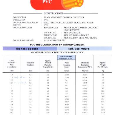
Mega Kabel Catalog Full 1w4b1s
November 2021 0
Mega Goal Catalog 5o5f4h
December 2021 0
Mega Miniatures Catalog 2012 4u2c4f
June 2020 5
Full Catalog 5e4319
December 2019 34
Thermoweld Master Catalog Full Catalog 2i266v
November 2019 222
Fritz 15 Full Por Mega 6i352b
November 2019 58More Documents from "Joseph Ting" 4d2h41
Mega Kabel Catalog Full 1w4b1s
November 2021 0
Briefing.ppt 733e3o
May 2022 0
Aplus Manual.pdf 6c4a40
October 2019 99
Bring Your Own Device Case Study 2a5n1h
December 2019 47
Definisi Keharmonian 6u2e3n
October 2019 37