Methven Nefa Pressure Reducing Valves Reference 2x4c59
This document was ed by and they confirmed that they have the permission to share it. If you are author or own the copyright of this book, please report to us by using this report form. Report 3b7i
Overview 3e4r5l
& View Methven Nefa Pressure Reducing Valves Reference as PDF for free.
More details w3441
- Words: 7,621
- Pages: 36
Product Range • 2011
1
PRESSURE CONVERSION
4
100
11
40
12
��.�
80
8
10
4 9
5
�.�
5
50
1
8 30
40
8
60
10
70
3
80
20
90
300
50
1 psi
1 m H2O
1 bar
1 kPa
2.989
6.895
9.807
100
1
kPa
m H2O
80
0.10197
1
10.197
0.3048
0.7031
1
0.02989
0.06895
0.09807
0.01
bar
MULTIPLY BY TO CONVERT INTO
40
1 ft H2O
4
100
110
120
5
130
140
psi
0.4335
1
1.4223
14.50
0.1450
700
900
1
2.3067
3.2808
33.455
0.3346
ft H2O
140
1000
120
800
90
600
70
500
60
400
30
200
7 40
6 4 2 50
6
90
30
9
9
70
�.�
7
60
20
6
30 10 3
3 20 7 2
1.5
5
UNIT TO CONVERT
Quick pressure conversions can be read off scales. e.g. 7.6 mH2O = 25 ftH2O = 75 kPa = 11 psi approx.
6 20
100
150
2 10
psi Gauge kPa 10 Head of Water meters feet 1 3.5 in mm
Pressure Length
INTRODUCTION NEFA valves are designed and manufactured to New Zealand Standards and comply with the requirements of the New Zealand Building Code. This booklet has been compiled to assist you with the installation of NEFA products. Installation of valves should always be carried out by a qualified plumber and must comply with the requirements of the New Zealand Building Code and Local Territorial Authority. Refer to the Building Code Compliance Document G12 Water Supplies available from the Department of Building and Housing. While every effort has been made to ensure the accuracy of information included in this publication, the publisher takes no responsibility for errors or omissions. This publication is copyright protected and all rights are reserved.
INDEX
Pressure Reducing Feed Valve . . . . . . . . . . . 4 Pressure and Vacuum Relief Valve . . . . . . . . 4 Temperature Limiting Valve . . . . . . . . . . . . . 8 Pressure Limiting Valve . . . . . . . . . . . . . . 10 Mains Pressure Inlet Control Valve . . . . . . . . 12 Mains Pressure Tempering Valve . . . . . . . . . 14 High Performance Solar Tempering Valve . . . . 16 Cold Water Expansion Valve . . . . . . . . . . . 18 15mm 3-in-1 Filter Stopcock & Non-Return Valve . . . 20 20mm 3-in-1 Filter Stopcock & Non-Return Valve . . . 22 Water Heater Installation Checklist . . . . . . . 24 Mains Pressure Installation Guidelines . . . . . . 25 Low Pressure Installation Guidelines . . . . . . . 26 Troubleshooting Guide . . . . . . . . . . . . . . 30 NEFA Valve Packs . . . . . . . . . . . . . . . . . 32 NEFA Spare Parts & Service Kits . . . . . . . . . 34
3
FEATURES
•• •• •• •• •• •• ••
Forged Dezincification Resistant (DR) brass body Superior flow rate Adjustable outlet pressure Silicone diaphragm and Jumper Washer Acetal valve seat Easily serviced Complies with the requirements of NZBC G12
SPECIFICATIONS
•• •• •• •• •• •• ••
•• •• ••
Conforms to NZS:4608 Factory set outlet pressures: 3.7 m/7.6 m/12.2 m Maximum inlet pressure 2000 kPa Maximum temperature 60°C For 3.7 m / 7.6 m - Settable from 2.5 m to 11 m Adjustment 1 turn approx 600 mm head For 12.2 m - Settable from 3 m to 18 m Adjustment 1 turn approx 1 m head Flow Rates at constant inlet pressure Inlet kPa 3.7 m 7.6 m / 12.2 m 300 kPa 42 l/min 43 l/min 500 kPa 50 l/min 55 l/min 700 kPa 60 l/min 64 l/min Connections: Inlet 15 mm (½ BSP) male Outlet 20 mm (¾ BSP) male Overall length 145 mm Main body diameter 125 mm
PRODUCT CODES NFV3715 NFV7615 NFV12215
4
3.7 m 7.6 m 12.2 m
NEFA Pressure Reducing Feed Valve NEFA Pressure Reducing Feed Valve NEFA Pressure Reducing Feed Valve
PRESSURE REDUCING FEED VALVE
INSTALLATION
•• •• •• ••
The NEFA Pressure Reducing Feed Valve can be installed in any orientation. But for ease of service install with the cap to the top. Factory setting allows for the NEFA Pressure and Vacuum Relief Valve to be fitted 1m above the NEFA Feed Valve. If they are installed level undo lock nut and turn adjustment screw two turns out of body. The valve should not be installed in the ground or in a situation where it could be subject to freezing. The valve should be installed where it can be easily accessed and when inside buildings above a safe tray.
Refer to Installation Guide, Pages 24 - 29 for detailed instructions.
IMPORTANT
•• ••
The water supply to a low pressure storage water heater must not exceed the maximum working pressure stated by the manufacturer. The NEFA Pressure Reducing Valve (Feed Valve) regulates the water supply pressure to the water heater to a suitable safe value. Install a NEFA 3-in-1 Filter Stopcock before the NEFA Feed Valve.
bridge jumper washer
cap fork
jet
diaphragm
Fig 1.
adjusting screw
5
FEATURES
•• •• •• •• •• •• ••
Forged Dezincification Resistant (DR) brass body Easy to service Withstands boiling temperatures Tamper proof; relief pressure permanently set Vacuum breaking jumper; prevents cylinder implosion on draining Integral vacuum break in outlet body; providing air break in drain line Complies with the requirements of NZBCG12
SPECIFICATIONS
•• •• •• •• •• •• •• ••
Conforms to NZS:4608 Factory set pressures 3.7 m/7.6 m/12.2 m Heat Rating 8 kW Maximum temperature 99°C Connections: Inlet: 20 mm (¾ BSP) male Drain: 15 mm (½ BSP) male Integral vacuum relief Overall length 105 mm Diameter 85mm
PRODUCT CODES NRV37 NRV76 NRV122
6
3.7 m 7.6 m 12.2 m
NEFA Pressure & Vacuum Relief Valve NEFA Pressure & Vacuum Relief Valve NEFA Pressure & Vacuum Relief Valve
PRESSURE & VACUUM RELIEF VALVE
INSTALLATION
•• ••
The NEFA Relief Valve must only be installed on a thermostatically controlled hot water system. Maximum heating capacity 8 kW per valve The drain line must not rise above the NEFA Relief Valve. It should run at a down grade out to atmosphere, to a point where the outlet cannot be obstructed or blocked and where expansion, or other vented water will not cause a hazard or a nuisance. It should not exceed 9 m in length and include not more than three 90° bends.
Refer to Installation Guide, Pages 24 - 29 for detailed instructions.
IMPORTANT
••
•• •• •• •• •• ••
When factory set, allowance is made for the NEFA Relief Valve to be fitted 1 m above the NEFA Pressure Reducing Feed Valve. If they are installed at the same level, as in an under sink installation, undo the NEFA Feed Valve lock nut and turn adjustment screw two turns anticlockwise. When servicing NEFA Relief Valves always use the original spring. Springs are not replaceable. When draining a water heating cylinder, the NEFA Relief Valve must be disconnected to ensure that adequate air can return to the cylinder to prevent cylinder collapse. A NEFA Relief Valve must not be installed where there is a risk of the valve freezing. The NEFA Relief Valve must not be installed on to a cylinder with an uncontrolled heat source i.e. solar or wetback. If the NEFA Relief Valve is fitted in a horizontal pipe run, the integral vacuum relief vent must be to the top. If the vacuum relief vent plug supplied with the NEFA Relief Valve is to be fitted to the Relief Valve body an alternative air break must be fitted in the drain line.
flap
diaphragm assembly
Fig 2.
vacuum break
spring
7
FEATURES
•• ••
•• •• •• •• ••
Cast Dezincification Resistant (DR) brass body Adjustable from 30°C to 65°C Fail Safe: Failure of cold water supply causes valve to close and shut off hot flow Configured for easy installation Non-return fitted to stop thermosyphon Serviceable Complies with the requirements of NZBC G12
SPECIFICATIONS
•• •• •• •• •• ••
Conforms to NZS:4617 Connections: All 20 mm ( ¾ BSP) male Factory set outlet temp 55°C Adjustable 30°C to 65°C Minimum 20 l/min at 35 kPa (3.5 m head) Maximum hot water temp 99°C
PRODUCT CODES NTLV
NEFA Temperature Limiting Valve
SETTING TEMPERATURE Tempering valves must be commissioned at time of installation. The delivered hot water temperature at any sanitary fixture used for personal hygiene shall not exceed: a) 45°C for early childhood centres, schools, old people’s homes, institutions for people with psychiatric or physical disabilities, hospitals, and b) 55°C for all other buildings. •• Before setting the valve, ensure the hot water source is switched on and supplying water within the specified hot water temperature limits. •• The recommended temperature differential hot supply/mixed outlet temperature to ensure thermal shut off is 15°C. •• At a flow rate of not less than 4 litres/minute, allow the water to flow 1-2 minutes to ensure the mixed water temperature has stabilised. •• Measure temperature at nearest outlet to tempering valve. •• The set outlet temperature is adjusted by turning the adjusting screw in the cover of the valve with a screwdriver. Clockwise decreases the temperature. Anticlockwise increases the temperature.
••
8
TEMPERATURE LIMITING VALVE LOW PRESSURE INSTALLATION
•• •• •• •• •• •• ••
The NEFA TLV can be installed in any orientation but ensure that the temperature adjusting screw is accessible. Make up pipe runs to the NEFA TLV with 20mm copper pipe. Do not braze or solder near valve. Ensure that the NEFA TLV is positioned a minimum of 350mm from the hot outlet of the water heater. Ensure that hot and cold supply pressures to the inlets of the NEFA TLV are equal. (Note the NEFA Cold Water Expansion Valve has a 20mm port to allow a simple pipe run to TLV). On header tanks and low head installations the NEFA TLV should be positioned as low as possible (at base of cylinder) to increase performance. When installing in a wetback system try to install as far from cylinder as possible to allow for cooling (maximum 90°C). Alternatively the NEFA TLV may be installed close to the outlets being serviced, but the supply pressures at the inlets to the NEFA TLV must be equal.
Refer to Installation Guide, Pages 24 - 29 for detailed instructions.
IMPORTANT
•• ••
••
Never install a Temperature Limiting Valve directly onto the outlet of the hot water cylinder. The NEFA TLV must not obstruct the hot water cylinder vent or NEFA Relief Valve. In the event of high temperature the NEFA TLV will shut the hot supply and not allow the vent or relief valve to relieve pressure in the cylinder. Where inlet supply pressures are not equal an additional non-return valve should be fitted on the hot water supply line. adjusting screw
valve assembly cold flow
mixed flow
thermostatic element
Fig 3.
hot flow
9
FEATURES
•• •• •• •• •• •• ••
DR brass construction Compact size Superior flow rate Pressure compensated Dry spring construction Ideal for protection of taps, pipe work and appliances from high supply pressures Complies with the requirements of NZBC G12
SPECIFICATIONS
•• •• •• ••
Conforms to NZS:4608 Factory set outlet pressures 350 kPa, 500 kPa Max inlet pressure 2000kPa Flow Rates at constant inlet pressure Inlet kPa 350 kPa 500 kPa 700 kPa 100 l/min 100 l/min
•• •• •• ••
Connections: Inlet and Outlet 20 mm (¾ BSP) male. Overall length 85 mm Main body diameter 40 mm Maximum temperature 80°C
PRODUCT CODES
10
NEPLV350MM20
350 kPa NEFA Pressure Limiting Valve
NEPLV500MM20
500 kPa NEFA Pressure Limiting Valve
PRESSURE LIMITING VALVE
INSTALLATION
•• •• •• •• ••
Install the NEFA Pressure Limiting Valve at entry to household to equalise complete system and protect tapware and appliances from excessive pressure. Install with flow in direction of arrow marked on body. Can be installed vertical or horizontal. The valve should not be installed in the ground or in a situation where it could be subject to freezing. The valve should be installed where it can be easily accessed.
Refer to Installation Guide, Pages 24 - 29 for detailed instructions.
IMPORTANT
•• ••
Install a NEFA 3-in-1 Filter Stopcock before the NEFA Pressure Limiting Valve. The NEFA Pressure Limiting Valve is factory set. It cannot be serviced and should not be dismantled.
control spring
jumper
color coded set pressure valve seat
Fig 4.
11
FEATURES
•• •• •• •• •• •• •• •• ••
Cast Dezincification Resistant (DR) brass body Superior flow rate Pressure compensated Set pressure adjustable Built-in Non-return valve prevents back flow Filter can be cleaned without shutting off any other valve Protection for entire household; taps, pipework and appliances from high supply pressures 60 mesh stainless steel filter efficiently prevents damage to hot water system by filtering foreign particles Complies with the requirements of NZBC G12
SPECIFICATIONS
•• •• •• •• •• •• ••
Conforms to NZS:4608 Maximum inlet pressure 2000 kPa Set pressure adjustable 100 kPa to 600 kPa Flow rate of 112 l/min on 20 mm pipe work at 700 kPa supply pressure 20 mm (¾ BSP) male inlet and outlet Overall length 145 mm, main body diameter 53 mm Maximum temperature 65°C
PRODUCT CODES NPC500
500 kPa NEFA Mains Pressure Inlet Control Valve
PRESSURE ADJUSTMENT
•• ••
12
The NPC is factory set as indicated on the valve; however the set outlet pressure can be increased or decreased if required. Using a screwdriver rotate the adjusting screw shown in Fig 5. to achive the desired outlet pressure. To increase the set pressure, turn the screwdriver clockwise (+). To decrease the set pressure, turn the screwdriver anti-clockwise (-).
MAINS PRESSURE INLET CONTROL VALVE
4-in-1 ISOLATION, FILTER, PRESSURE LIMITING & NON-RETURN
INSTALLATION
••
•• ••
A NEFA NPC500 Mains Pressure Inlet Control Valve should be installed in the main water supply at point of entry. This will provide a point of isolation, a filtered water supply and balanced water pressure to the whole house, protecting tapware and appliances from excessive pressure. The valve should be installed where it can be easily accessed, and when inside buildings above a safe tray where water from servicing the filter will not cause damage. The NEFA Mains Pressure Inlet Control Valve can be installed in any orientation, the recommended orientation is with the filter cap facing down to allow foreign particles to fall away when the filter is removed for cleaning.
Refer to Installation Guide, Pages 24 - 29 for detailed instructions.
SERVICING
•• •• ••
To remove and clean the filter (Refer Fig 5.): 1. Turn the isolation control clockwise to the closed position. 2. Unscrew the filter cap. 3. Withdraw the filter and clean it. To reassemble, reverse the above procedure. Care should be taken not to damage the filter. To ensure full flow it is recommended that the filter should be inspected and cleaned at 12 month intervals or more often if required.
set pressure adjustment
isolation hand control
diaphragm
filter
filter cap
Fig 5.
jumper
non–return
13
FEATURES
•• •• •• •• •• •• •• ••
Provides safe controlled water temperature to sanitary outlets Cast DR brass body Fail Safe: Failure of cold water supply causes valve to close and shut off hot flow Advanced polymers give greater resistance to calcium deposits Factory tested and set at 55ºC adjustable from 35ºC to 58ºC Integral Non-Return on hot and cold - ideal for commercial installations Tamper proof adjustment special tool supplied Maximum Hot Inlet Temperature 90°C
SPECIFICATIONS
•• •• •• •• •• •• •• •• •• •• •• •• •• ••
Conforms to: NZS4617:1989 Connections: 20 mm (¾ BSP) male Recommended outlet temperature range: 45°C to 55°C (2) Factory setting (must be commissioned on site): 55°C nominal Accuracy of mixed outlet temperature: ± 3°C Cold water supply: 5°C to 25°C Hot water supply: 60°C to 90°C (1) Hot water / mixed water temperature differential: 15°C minimum Supply pressure – static: 1600 kPa maximum Supply pressure – dynamic: 200 kPa minimum 500 kPa maximum Max permitted pressure variations at either inlet: ± 10% maximum (4,5) (from supply pressure at commissioning) Pressure supply differential – dynamic : 3:1 maximum (3) (at time of commissioning) Minimum flow rate: 4 litres/minute
Notes: 1) The Building Code Approved Document G12 clause 6.14 states that water shall be stored at not less than 60°C to inhibit the growth of legionella bacteria. To obtain good tempering valve response the cylinder thermostat should be set at a minimum of 65°C. 2) The valve can be set as low as 35°C or as high as 58°C, depending on site conditions. (These temperatures are outside the optimum working range of the valve and the requirements of G12). 3) The maximum ratio permitted between supply pressures, under dynamic flow operation. It is recommended at time of commissioning that hot and cold pressures be as equal as possible. 4) The maximum permitted pressure variation in either supply from commissioning pressures in order to maintain the outlet temperature to ±3°C. 5) Note: Steps should be taken to eliminate any causes of rapid changes in supply pressures, as this may result in an outlet temperature spike greater than ±3°C from commissioned temperature. If a spike occurs it may take a few seconds for the temperature to stabilise back to within ±3°C.
PRODUCT CODES NMTV
14
NEFA Mains Pressure Tempering Valve
MAINS PRESSURE TEMPERING VALVE
INSTALLATION
••
•• ••
Do not install an NMTV directly onto a hot water cylinder. It is recommended that the valve be installed as close to the hot water source as possible. For optimum performance install with a 150mm thermosyphon between the cylinder outlet and hot inlet. (Refer Fig 10. Page 25). Strainers are essential to prevent debris entering the NMTV that could prevent it working effectively. All NMTV installations should have line strainers fitted. It is recommended that a NEFA NPC500 valve (with filter/strainer) is installed upstream of the cold inlet. Where installing into installations with separate hot and cold supply’s install a non-return valve on hot water supply or use the NEFA high performance solar tempering valve.
Refer to Installation Guide, Pages 24 - 29 for detailed instructions.
IMPORTANT Tempering valves must be commissioned at time of installation. The delivered hot water temperature at any sanitary fixture used for personal hygiene shall not exceed: a) 45°C for early childhood centres, schools, old people’s homes, institutions for people with psychiatric or physical disabilities, hospitals, and b) 55°C for all other buildings. •• Before setting the valve, ensure the hot water source is switched on and supplying water within the specified hot water temperature limits. •• The recommended temperature differential hot supply/mixed outlet temperature to ensure thermal shut off is 15°C. •• At a flow rate of not less than 4 litres/minute, allow the water to flow 1-2 minutes to ensure the mixed water temperature has stabilised. •• Using a thermometer, measure temperature at nearest outlet to tempering valve. •• Using the adjusting tool supplied, rotate the adjusting spindle (H) hot or (C) cold as indicated on the tool until the required set temperature is achieved.
••
cap set temperature adjustment
hot flow
cold flow
valve
non–return valve
thermal element
Fig 6.
mixed flow
15
FEATURES
•• •• •• •• •• •• •• ••
Provides safe controlled water temperature to sanitary outlets Cast DR brass body Fail Safe: Failure of cold water supply causes valve to close and shut off hot flow Advanced polymers give greater resistance to calcium deposits Factory tested and set at 55ºC adjustable from 35ºC to 58ºC Integral Non-Returns on hot and cold - ideal for commercial installations Tamper proof adjustment special tool supplied Maximum Hot Inlet Temperature 99°C
SPECIFICATIONS
•• •• •• •• •• •• •• •• •• •• •• •• •• ••
Conforms to: NZS4617:1989 Connections: 20 mm (¾ BSP) male Recommended outlet temperature range: 45°C to 55°C (2) Factory setting (must be commissioned on site): 55°C nominal Accuracy of mixed outlet temperature: ± 3°C Cold water supply: 5°C to 25°C Hot water supply: 60°C to 99°C (1) Hot water / mixed water temperature differential: 15°C minimum Supply pressure – static: 1600 kPa maximum Supply pressure – dynamic: 200 kPa minimum 500 kPa maximum Max permitted pressure variations at either inlet: ± 10% maximum (4,5) (from supply pressure at commissioning) Pressure supply differential – dynamic : 3:1 maximum (3) (at time of commissioning) Minimum flow rate: 4 litres/minute
Notes: 1) The Building Code Approved Document G12 clause 6.14 states that water shall be stored at not less than 60°C to inhibit the growth of legionella bacteria. To obtain good tempering valve response the cylinder thermostat should be set at a minimum of 65°C. 2) The valve can be set as low as 35°C or as high as 58°C, depending on site conditions. (These temperatures are outside the optimum working range of the valve and the requirements of G12). 3) The maximum ratio permitted between supply pressures, under dynamic flow operation. It is recommended at time of commissioning that hot and cold pressures be as equal as possible. 4) The maximum permitted pressure variation in either supply from commissioning pressures in order to maintain the outlet temperature to ±3°C. 5) Note: Steps should be taken to eliminate any causes of rapid changes in supply pressures, as this may result in an outlet temperature spike greater than ±3°C from commissioned temperature. If a spike occurs it may take a few seconds for the temperature to stabilise back to within ±3°C.
PRODUCT CODES NSTV20
16
High Performance Solar Tempering Valve
HIGH PERFORMANCE SOLAR TEMPERING VALVE INSTALLATION
••
•• ••
Do not install an NMTV directly onto a hot water cylinder. It is recommended that the valve be installed as close to the hot water source as possible. For optimum performance install with a 150mm thermosyphon between the cylinder outlet and hot inlet. (Refer Fig 10. Page 25). If installed at an outlet fixture, 1m of pipe must be installed between the NMTV and the outlet. Strainers are essential to prevent debris entering the NMTV that could prevent it working effectively. All NMTV installations should have line strainers fitted. It is recommended that a NEFA NPC500 valve (with filter/strainer) is installed upstream of the cold inlet.
Refer to Installation Guide, Pages 24 - 29 for detailed instructions.
IMPORTANT Tempering valves must be commissioned at time of installation. The delivered hot water temperature at any sanitary fixture used for personal hygiene shall not exceed: a) 45°C for early childhood centres, schools, old people’s homes, institutions for people with psychiatric or physical disabilities, hospitals, and b) 55°C for all other buildings. •• Before setting the valve, ensure the hot water source is switched on and supplying water within the specified hot water temperature limits. •• The recommended temperature differential hot supply/mixed outlet temperature to ensure thermal shut off is 15°C. •• At a flow rate of not less than 4 litres/minute, allow the water to flow 1-2 minutes to ensure the mixed water temperature has stabilised. •• Using a thermometer, measure temperature at nearest outlet to tempering valve. •• Using the adjusting tool supplied, rotate the adjusting spindle (H) hot or (C) cold as indicated on the tool until the required set temperature is achieved.
••
Temperature adjustment
Filter & Non-return Cold inlet Hot inlet Valve member
Thermostatic element
Fig 6.
Mixed outlet
17
FEATURES
•• •• •• ••
•• •• •• •• •• ••
Forged Dezincification Resistant (DR) brass body Stainless steel valve seat standard Incorporates an outlet port for running direct equal pressure cold supply to TLV Design of valve allows perfect washer maintaining excellent seating at low relief pressure settings Diaphragm sealed spring chamber eliminates O-ring drag associated with normal piston type sealing Integral non-return valve supplied to conform to NZBC G12 Serviceable Easy to operate flushing mechanism Valve can be used as cylinder drain Complies with the requirements of NZBC G12
SPECIFICATIONS
•• •• •• ••
Conforms to NZS:4608 Connections: Inlet, Outlet and TLV Outlet 20 mm (¾ BSP) male Drain 15 mm (½ BSP) male Factory set for 7.6 m head and 850 kPa systems Valve seat stainless steel
PRODUCT CODES NECWE76 NECWE700
18
76 kPa NEFA Cold Water Expansion Valve 700 kPa NEFA Cold Water Expansion Valve
COLD WATER EXPANSION VALVE
INSTALLATION
••
••
The drain line must not rise above the NEFA CWE Valve. It should run at a down grade out to atmosphere, to a point where the outlet cannot be obstructed or blocked and where expansion, or other vented water will not cause a hazard or a nuisance. It should not exceed 9m in length and include not more than three 90° bends. Observe flow direction on body.
Refer to Installation Guide, Pages 24 - 29 for detailed instructions.
IMPORTANT
•• •• ••
The NEFA CWE Valve is factory set to relieve at a pressure slightly less than the NEFA Pressure Relief Valve and is not field adjustable. For low pressure systems the NEFA Pressure Reducing Feed Valve setting must be reduced 1½ turns to avoid water wastage. For mains pressure systems a NEFA Pressure Limiting Valve must be fitted if the cold supply pressure is greater than 500 kPa.
manual flush control
diaphragm sealed dry spring chamber drain connection stainless steel valve seat
integral non–return
tempering valve connection (not shown)
Fig 7.
19
FEATURES
•• •• •• •• ••
Forged Dezincification Resistant (DR) brass body Prevents damage to water system by filtering foreign particles Filter can be cleaned without shutting off any other valve 60 mesh stainless steel filter ensures efficient capture of foreign particles Built-in non-return valve prevents back-flow
SPECIFICATIONS
•• •• •• •• ••
Connections: Inlet 15 mm (½ BSP) male Outlet 15 mm (½ BSP) female Length 75 mm Height 110 mm 60 mesh stainless steel filter Maximum inlet pressure 2000 kPa
PRODUCT CODES N311
20
NEFA 15mm 3-in-1 Filter Stopcock & Non-return Valve
15mm 3-in-1 FILTER STOPCOCK & NON-RETURN VALVE
INSTALLATION
•• •• •• •• ••
Install at inlet to household system to protect the complete household. Install the valve with flow in the direction as marked on the valve. The NEFA 15mm 3-in-1 valve should be fitted with hand wheel down to allow foreign particles to fall away when the filter is removed. The valve should not be installed in the ground or in situation where it could be subject to freezing. The valve should be installed where it can be easily accessed.
IMPORTANT
••
•
To ensure full flow through the valve it is recommended that the filter should be removed and cleaned every 12 months, depending on the water supply.
SERVICING To remove and clean filter (Refer Fig 8.): 1. Turn handle in clockwise direction and firmly shut off inlet water to valve. 2. Remove handle retaining screw and remove hand wheel from spindle. 3. Unscrew filter cover anticlockwise and remove by sliding off spindle. 4. Remove filter and clean. 5. Reassemble in the reverse order.
non–return flap
filter cover spindle handle
Fig 8.
21
FEATURES
• • • • • •
Forged Dezincification Resistant (DR) brass body Prevents damage to water system by filtering foreign particles Filter can be cleaned without shutting off any other valve 60 mesh stainless steel filter ensures efficient capture of foreign particles Built in non-return valve prevents back-flow Design allows high flow rate through valve
SPECIFICATIONS
•
• • • • •
Connections: Inlet 20 mm (¾ BSP) male Outlet 20 mm (¾ BSP) female Length 90 mm Height 100 mm 60 mesh stainless steel filter Maximum inlet pressure 2000 kPa Flow rate at 700 kPa inlet pressure: 125 l/min
PRODUCT CODES NE31120
22
NEFA 20mm 3in1 Filter Stopcock & Non-return Valve
20mm 3-in-1 FILTER STOPCOCK & NON-RETURN VALVE INSTALLATION
• • • • •
Install at inlet to household system to protect the complete household. Install the valve with flow in the direction as marked on the valve. The NEFA 20mm 3-in-1 valve should be fitted with the filter cap down to allow foreign particles to fall away when the filter is removed for cleaning. The valve should not be installed in the ground or in situation where it could be subject to freezing. The valve should be installed where it can be easily accessed.
IMPORTANT
•
To ensure full flow through the valve it is recommended that the filter should be removed and cleaned every 12 months, depending on the water supply.
SERVICING
•
To remove and clean filter (Refer Fig 9.): 1. Turn handle clockwise to shut off inlet water to valve. 2. Unscrew filter cap anticlockwise and remove from valve body. 3. Withdraw filter element and clean. 4. Reassemble in the reverse order taking care not to damage filter. Note the filter cover only needs to be hand tight as it is o-ring sealed.
handle
non–return valve
filter cap
Fig 9.
23
INSTALLATION CHECKLIST THIS BOOKLET IS ISSUED AS A GENERAL GUIDE ONLY Refer to the water heater manufacturer’s installation instructions for specific requirements. Installation of valves should always be carried out by a qualified plumber and must comply with the requirements of the New Zealand Building Code and local Territorial Authority. Refer to the New Zealand Building Code Compliance Document G12 Water Supplies available from the Department of Building and Housing. If you have any questions please Methven Limited Customer Service free phone 0800 804 222
ALWAYS
•• •• •• •• •• •• ••
Always connect NEFA valves to water heaters with non-ferrous fittings and copper pipe. Always use copper pipe for drain lines from relief valves and cold water expansion valves. Always check water supply pressure with a pressure gauge. Always flush pipes before connecting valves. Always check for the correct flow direction through valves as indicated by markings on the valve and fitting instructions. Always ensure that there is access to the hot water cylinder and valving in case future adjustment or replacement is required. Measure delivered hot water temperature with thermometer at sanitary outlets.
NEVER
•• •• •• •• •• •• ••
24
Never install a tempering valve directly onto the outlet of the hot water cylinder. Never attempt to adjust valves or tamper with seals, except as directed in instruction sheets. Never attempt to adjust the setting of pressure relief, temperature pressure relief or cold water expansion valves. Never fit a stop valve or any obstruction in the piping between the connection from the hot water cylinder and the inlet of a Pressure Relief Valve. Never fit a stop valve or any obstruction in a pressure relief or cold water expansion drain line. Never expose valves to a naked flame or heat. Heat will destroy the seals and the sealing parts of the valve. Never allow thread sealing tape to extend over the end of threads, excess tape may be cut free when making connections and affect the function of the valve.
INSTALLATION GUIDELINES
MAINS PRESSURE
MAINS PRESSURE INSTALLATION TPR VALVE
HOT WATER TO LAUNDRY & KITCHEN 150mm Recommended
TEMPERED WATER TO BATHROOM AND SHOWER BALANCED PRESSURE COLD WATER TO HOUSEHOLD
NEFA NMTV MAINS PRESSURE TEMPERING VALVE
MAINS PRESSURE STORAGE WATER HEATER DRAIN
COLD WATER MAINS INLET BALL VALVE NEFA NPC500 MAINS PRESSURE INLET CONTROL WITH INTEGRAL ISOLATION & FILTER
Fig 10.
•• •• ••
•• ••
NEFA NECWE700 COLD WATER EXPANSION VALVE WITH NON-RETURN DRAIN
Always install a NEFA NPC500 Mains Pressure Inlet Control Valve in the main water supply at point of entry. This will provide a point of isolation, a filtered water supply and balanced water pressure to the whole house. NEFA Cold Water Expansion Valve drain lines should not exceed 3m in length and include not more than three 90º bends. For optimum performance the cold water supply to the NEFA tempering valve must be at the same pressure as the hot water supply from the cylinder to the tempering valve. The NEFA Cold Water Expansion Valve has an outlet port to allow a simple connection to the tempering valve. Use 20mm copper pipe to make up hot and cold supply connections to the tempering valve. In order to ensure that the NEFA tempering valve works efficiently set the hot water cylinder thermostat to between 65°C to 70°C. Where separate hot and cold water supplies are delivered to the NEFA tempering valve ensure the pressures are balanced and a nonreturn valve is fitted to the hot water supply. With average domestic hot water usage 2 to 4 litres of water from thermal expansion can be expected.
•• ••
Faulty valves must be immediately repaired or replaced. These are safety devices and must be in excellent working order.
25
LOW PRESSURE — VALVE VENTED
LOW PRESSURE — VALVE VENTED INSTALLATION HOT WATER TO LAUNDRY & KITCHEN
NEFA N311 3in1 FILTER STOPCOCK & NON-RETURN COLD WATER MAINS INLET
Fig 11.
••
•• •• •• •• ••
26
NEFA NTLV TEMPERING VALVE WATER HEATER TO NZS 4602 WITH THERMOSTAT & ALT SIDE THERMAL ENTRY ENERGY CUT OUT BALL VALVE
NEFA NFV7615 PRESSURE REDUCING FEED VALVE
NEFA NECWE76 COLD WATER EXPANSION VALVE WITH NON-RETURN
80mm MIN
TEMPERED WATER TO BATHROOM AND SHOWER
NEFA NRV76 PRESSURE & VACUUM RELIEF VALVE DRAIN
CYLINDER DRAIN
DRAIN
Always install a NEFA 3-in-1 Filter Stopcock in the main water supply at point of entry. This will protect the whole house and make isolation easy for servicing.
PRESSURE REDUCING FEED VALVE NEFA Pressure Reducing Feed Valves come factory set at 3.7 m, 7.6 m or 12.2 m as indicated on the valve. The valve will operate in any position but for ease of service the valve should be installed with the cap up. In low pressure installations with a NEFA Cold Water Expansion Valve the NEFA Pressure Reducing Feed Valve adjusting screw must be turned 1½ turns anticlockwise to avoid water wastage. When installed on a side entry cylinder a thermosyphon loop of 150mm at the entry to the cylinder will help prolong the life of the NEFA Pressure Reducing Feed Valve. When set at the factory, allowance is made for the NEFA Relief Valve to be fitted 1 m above the NEFA Feed Valve. If they are installed level as in under sink heaters undo lock nut and turn adjustment screw 1½ turns anticlockwise.
INSTALLATION GUIDELINES
•• •• •• •• •• •• •• ••
••
SETTING THE OUTLET PRESSURE OF NEFA FEED VALVE Switch off the power to the Hot Water Cylinder. Run a hot tap for 5-10 seconds. This eliminates any thermal expansion in the water heater. For open vented systems observe the vent pipe. For systems with a NEFA Relief Valve observe the outlet from the drain. For systems with a NEFA Cold Water Expansion Valve observe the drain from the Cold Water Expansion Valve. Release the lock nut on the adjusting screw of the NEFA Feed Valve and wind the adjusting screw clockwise to increase the outlet pressure until water is observed at the vent. Slowly reduce the outlet pressure from the pressure reducing valve by turning adjusting screw anticlockwise until water from vent stops. When water has stopped the pressure from the outlet of the NEFA Feed Valve is now balanced at the pressure of the relief or vent. For the system to be efficient and to avoid wastage there must be a differential between the venting pressure and the NEFA Feed Valve’s set outlet pressure. Wind the adjusting screw of the NEFA Feed Valve a further ½ to ¾ turn anticlockwise.
SERVICING THE JUMPER WASHER OF NEFA FEED VALVE
•• •• •• •• •• •• •• ••
Isolate water supply to valve at inlet and outlet. Remove cap by unscrewing from valve body. Remove bridge by sliding out of fork. Lift off jumper valve and remove jumper washer. Inspect jumper valve and valve seat on jet for damage. Jet is sealed by o-ring and can be unscrewed from body. Replace defective parts and reassemble. Restore water pressure and reset outlet pressure of feed valve.
cap
jumper valve jumper washer bridge fork
adjusting screw lock nut
ccw -
+ cw
Fig 12.
27
LOW PRESSURE — OPEN VENTED
LOW PRESSURE — OPEN VENTED INSTALLATION VENT PIPE HOT WATER TO LAUNDRY & KITCHEN
ROOF
LINE
7.6 METRES MAX. 3.7 METRES MIN. NOT TO EXCEED WORKING PRESSSURE STATED ON CYLINDER.
TEMPERED WATER TO BATHROOM AND SHOWER NEFA NTLV TEMPERING VALVE
NEFA N311 3in1 FILTER STOPCOCK & NON-RETURN
ALT SIDE ENTRY
NEFA NFV7615 PRESSURE REDUCING FEED VALVE
WATER HEATER TO NZS 4602 WITH THERMOSTAT & THERMAL ENERGY CUT OUT
BALL VALVE
COLD WATER MAINS INLET CYLINDER DRAIN
Fig 13.
•• ••
In areas subject to freezing vent pipes shall be insulated; NZBC G12 Clause 7.2. The standing water level shall be a minimum of 300mm below insulation. The use of an expansion control valve can help protect the water heater.
LOW PRESSURE — HEADER TANK INSTALLATION VENT PIPE ROOF
2.5 METRES MIN HEAD REQUIRED AT TEMPERING VALVE COLD WATER MAINS INLET
NEFA N311 3in1 FILTER STOPCOCK & NON-RETURN
HIGH PRESSURE COLD WATER TO HOUSEHOLD
••
28
LINE
7.6 METRES MAX. 3.7 METRES MIN. NOT TO EXCEED WORKING PRESSSURE STATED ON CYLINDER.
HOT WATER TO LAUNDRY & KITCHEN
TEMPERED WATER TO BATHROOM AND SHOWER NEFA NTLV TEMPERING VALVE
WATER HEATER TO NZS 4602 WITH THERMOSTAT & ALT SIDE THERMAL ENTRY ENERGY CUT OUT BALL VALVE
BALANCED PRESSURE COLD WATER TO SHOWER
CYLINDER DRAIN
Fig 14.
With low pressure header tank installations the NEFA tempering valve requires a minimum of 2.5m head and for best performance install the NEFA tempering valve as close to the base of the cylinder as possible using 20mm copper pipe.
INSTALLATION GUIDELINES
••
••
•• •• •• •• •• •• •• ••
•• ••
PRESSURE RELIEF VALVES ALTERNATIVE RELIEF VALVE NEFA Pressure Relief Valves INSTALLATION are factory set to 3.7 m 7.6 m or 12.2 m head as indicated 80 mm MIN on the valve and cannot be DRAIN adjusted. Relief valves must only be NEFA NRV76 PRESSURE & VACUUM installed on a thermostatically WATER HEATER RELIEF VALVE TO controlled hot water cylinder NZS 4602 INSTALL WITH INTEGRAL WITH with a maximum heating VACUUM BREAK VENT HOLE UP THERMOSTAT capacity of 8 kW. & THERMAL Relief Valves must not be ENERGY CUT OUT fitted to a water heater with Fig 15. a wetback or where solar heating is used. To protect the NEFA Relief Valve from excessive heat we recommend that the relief valve is fitted 80 mm below the top of the cylinder as shown in Fig 11. Alternatively install the NEFA Relief Valve after a thermosyphon loop of a minimum of 80 mm as shown in Fig 15. The NEFA Relief Valve should not be fitted more than 300mm above the cylinder. Except as detailed under existing installations below. Drain lines from the NEFA Cold Water Expansion Valve and the NEFA Relief Valve must fall continuously from the outlet of the valves. Drain lines should not exceed 3m in length and include not more than three 90° bends. Drain lines should run to a point where the outlet cannot be obstructed or blocked and where expansion and other vented water is discharged to atmosphere and will not cause a hazard or a nuisance. If there is a possibility of the drain freezing, an air break in the drain at the water heater is required. With average domestic hot water usage 2 to 4 litres of EXISTING INSTALLATION water from thermal expansion can be expected. To increase the pressure of an 3.7 METRES MAX. existing installation with an HEIGHT FROM CYLINDER BASE open vent to the roof, a NEFA NEFA NRV37 TOTAL HEAD 3.7 m Relief Valve can be fitted PRESSURE & VACUUM VENT + RELIEF VALVE LINE RELIEF VALVE ROOF to the vent not more than NOT TO EXCEED WORKING PRESSSURE 3.7 m above the bottom of the STATED ON CYLINDER cylinder as shown in FIG 16. WATER HEATER The pressure reducing valve TO should then be adjusted, refer NZS 4602 WITH Fig 12 Page 27. THERMOSTAT & The vent pipe must be bent as THERMAL ENERGY shown so that the outlet of the CUT OUT Fig 16. NEFA Relief Valve points down. This installation is not suitable for areas subject to freezing.
29
FAULT FINDING FOR HOT WATER INSTALLATIONS
If the Cold Water Expansion Valve (CWE) drain or vent pipe drips.
If the Relief valve drain drips.
Is a Cold Water Expansion Valve (CWE) fitted?
NO
Check for thermal expansion. Turn water heater energy supply off. Run hot tap for 5-10 seconds.
YES Install CWE with correct pressure
NO
NO
Check correct pressure CWE is fitted
Has dripping stopped?
YES
YES
Check CWE drain line is not blocked
Drip is normal thermal expansion. Check thermostat is not set to high. Average domestic hot water useage can expect 2-4 liters of expansion water per day.
YES Unblock CWE drainline
Has Relief Valve stopped dripping?
YES
NO CHECK RELIEF VALVE High Pressure
Low Pressure
Does the Temperature Pressure Relief Valve (TPR) drip or ‘gush’ intermittently
Turn off water supply to hot water cylinder. Dismantle the Relief Valve and clean. Check seat, washer and diaphragm for damage. Replace if necessary. Refit Relief Valve. Turn water on. Note: Due to factory settings, springs cannot be exchanged.
Gush Check Thermostat. TPR is relieving high temperature water.
30
Drip Replace TPR
Nefa Feed, CWE and Relief Valves are OK. Turn water heater energy supply on.
NO
TROUBLESHOOTING GUIDE
Check for cross feeding. Turn off water supply to the hot water cylinder only.
Has dripping stopped?
CHECK SUPPLY PRESSURE
NO
YES Check and rectify any cross feeding (inadvertent high pressure connection to low pressure) through a mixing unit e.g. shower mixer, single lever mixer etc. Turn water back on. Note: Cold feed to TLV must come off cold cylinder feed pipe AFTER the feed valve or PLV.
YES
High Pressure
Low Pressure
Remove the Feed Valve cap. Check jet, seat and washer for damage. Replace if necessary. Turn water back on.
Is a Pressure Limiting Valve (PLV) fitted?
NO
YES
Install correct PLV
Replace PLV
Has dripping stopped?
NO Check CWE Turn off water supply to the hot water cylinder. Dismantle the CWE and clean. Check seat, washer and diaphragm for damage. Replace with CWE kit if necessary. Turn water on. Note: CWE is factory set and cannot be adjusted.
YES
Has dripping stopped?
NO Check Feed Valve setting matches CWE / vent pipe height. (Low pressure systems only.) Refer setting instructions.
31
MAINS PRESSURE
NEMPK
MAINS PRESSURE INSTALLATION PACK 500 kPa
20 mm
NPC500
Mains Pressure Inlet Control Valve (Pressure Limiting, Isolation & Filter)
NMTV
Mains Pressure Tempering Valve
NECWE700 Cold Water Expansion Valve (with Intergral Non-Return) BV78820
20 mm M&F Ball Valve
LOW PRESSURE
NVKLP
LOW PRESSURE INSTALLATION PACK 7.6 m Head NFV7615
Pressure Reducing Feed Valve (7.6 m)
NRV76
Pressure Relief Valve (7.6m) (With Integral Vacuum Break)
NECWE76 Cold Water Expansion Valve (7.6 m) (with Intergral Non-Return)
32
NTLV
Temperature Limiting Valve
N311
Filter, Stop cock & Non-return
BV78820
20 mm M&F Ball Valve
VALVE PACKS
MAINS PRESSURE
NMPKSOL
MAINS PRESSURE SOLAR INSTALLATION PACK 500 kPa
20 mm
NPC500
Mains Pressure Inlet Control Valve (Pressure Limiting, Isolation & Filter)
NSTV20
High Performance Solar Tempering Valve
NECWE700 Cold Water Expansion Valve (with Intergral Non-Return) BV78820
20 mm M&F Ball Valve
MEDIUM PRESSURE
NVK122
MEDIUM PRESSURE INSTALLATION PACK 12.2m Head NFV12215
Pressure Reducing Feed Valve (12.2 m)
NRV122
Pressure Relief Valve (12.2m) (With Integral Vacuum Break)
NECWE120 Cold Water Expansion Valve (12 m) (with Intergral Non-Return) NTLV
Temperature Limiting Valve
N311
Filter, Stop cock & Non-return
BV78820
20 mm M&F Ball Valve
33
NEFA SPARE PARTS & SERVICE KITS PRESSURE REDUCING FEED VALVE SPNFVSK Nefa Feed Valve Service Kit NFVW Nefa Feed Valve Silicon Washer (pack 20) 920606 Nefa Feed Valve Jumper Assembly NFVD Nefa Feed Valve Diaphragm 920533 Nefa Feed Valve Diaphragm Assembly with Screw and Nut 920541 Nefa Feed Valve Fork 920568 Nefa Feed Valve Fork Bridge NFVCJ Nefa Feed Valve Replacement Jet Kit 920607 Nefa Feed Valve Plastic Cap and O-ring 920509 Nefa Feed Valve Cap O-ring (pack 5) 920657 Nefa Feed Valve Spring 3.7m and 7.6m 920665 Nefa Feed Valve Spring 12.2m 270031 Nefa Feed Valve Adjusting Screw and Nut 920495 Nefa Feed Valve Backing Plate 920673 Nefa Feed Valve Spring Cap PRESSURE AND VACUUM RELIEF VALVE SPNRVSK Nefa Relief Valve Service Kit NRVD Nefa Relief Valve Diaphragm Assembly NRVF Nefa Relief Valve Flap 15mm 3-in-1 FILTER STOPCOCK SP193113 Nefa Filter 311 15mm SP311FLAP Non-return Flap N311 15mm 786101 311 15mm Spindle O-ring SP31120SK Nefa Kit 20mm 3-in-1 NTLV TEMPERATURE LIMITING VALVE 782004 Nefa TLV Service Kit NPC500 MAINS PRESSURE INLET CONTROL VALVE 920700 Filter and O-ring Service Kit NON-RETURN NECWENRV
34
Nefa CWE Non-return Valve and Holder
SPARE PARTS & SERVICE KITS
www.methven.com Freecall: 0800 804 222 Freefax: 0800 805 222 Please note: While every effort is made to ensure that the details in this brochure were correct at the time of printing, Methven reserves the right to alter specifications or product from that shown. This brochure is printed on an environmentally responsible paper, elemental chlorine free. Printed with soy-based printing inks.
For detailed technical and warranty information, please visit www.methven.com.
Methven Limited
447 Rosebank Road, Private Bag 19996, Avondale, Auckland 1026, New Zealand, Telephone +64 9 829 0429, Facsimile +64 9 829 0439, Email [email protected] 280101 Issue D
May 2011
1
PRESSURE CONVERSION
4
100
11
40
12
��.�
80
8
10
4 9
5
�.�
5
50
1
8 30
40
8
60
10
70
3
80
20
90
300
50
1 psi
1 m H2O
1 bar
1 kPa
2.989
6.895
9.807
100
1
kPa
m H2O
80
0.10197
1
10.197
0.3048
0.7031
1
0.02989
0.06895
0.09807
0.01
bar
MULTIPLY BY TO CONVERT INTO
40
1 ft H2O
4
100
110
120
5
130
140
psi
0.4335
1
1.4223
14.50
0.1450
700
900
1
2.3067
3.2808
33.455
0.3346
ft H2O
140
1000
120
800
90
600
70
500
60
400
30
200
7 40
6 4 2 50
6
90
30
9
9
70
�.�
7
60
20
6
30 10 3
3 20 7 2
1.5
5
UNIT TO CONVERT
Quick pressure conversions can be read off scales. e.g. 7.6 mH2O = 25 ftH2O = 75 kPa = 11 psi approx.
6 20
100
150
2 10
psi Gauge kPa 10 Head of Water meters feet 1 3.5 in mm
Pressure Length
INTRODUCTION NEFA valves are designed and manufactured to New Zealand Standards and comply with the requirements of the New Zealand Building Code. This booklet has been compiled to assist you with the installation of NEFA products. Installation of valves should always be carried out by a qualified plumber and must comply with the requirements of the New Zealand Building Code and Local Territorial Authority. Refer to the Building Code Compliance Document G12 Water Supplies available from the Department of Building and Housing. While every effort has been made to ensure the accuracy of information included in this publication, the publisher takes no responsibility for errors or omissions. This publication is copyright protected and all rights are reserved.
INDEX
Pressure Reducing Feed Valve . . . . . . . . . . . 4 Pressure and Vacuum Relief Valve . . . . . . . . 4 Temperature Limiting Valve . . . . . . . . . . . . . 8 Pressure Limiting Valve . . . . . . . . . . . . . . 10 Mains Pressure Inlet Control Valve . . . . . . . . 12 Mains Pressure Tempering Valve . . . . . . . . . 14 High Performance Solar Tempering Valve . . . . 16 Cold Water Expansion Valve . . . . . . . . . . . 18 15mm 3-in-1 Filter Stopcock & Non-Return Valve . . . 20 20mm 3-in-1 Filter Stopcock & Non-Return Valve . . . 22 Water Heater Installation Checklist . . . . . . . 24 Mains Pressure Installation Guidelines . . . . . . 25 Low Pressure Installation Guidelines . . . . . . . 26 Troubleshooting Guide . . . . . . . . . . . . . . 30 NEFA Valve Packs . . . . . . . . . . . . . . . . . 32 NEFA Spare Parts & Service Kits . . . . . . . . . 34
3
FEATURES
•• •• •• •• •• •• ••
Forged Dezincification Resistant (DR) brass body Superior flow rate Adjustable outlet pressure Silicone diaphragm and Jumper Washer Acetal valve seat Easily serviced Complies with the requirements of NZBC G12
SPECIFICATIONS
•• •• •• •• •• •• ••
•• •• ••
Conforms to NZS:4608 Factory set outlet pressures: 3.7 m/7.6 m/12.2 m Maximum inlet pressure 2000 kPa Maximum temperature 60°C For 3.7 m / 7.6 m - Settable from 2.5 m to 11 m Adjustment 1 turn approx 600 mm head For 12.2 m - Settable from 3 m to 18 m Adjustment 1 turn approx 1 m head Flow Rates at constant inlet pressure Inlet kPa 3.7 m 7.6 m / 12.2 m 300 kPa 42 l/min 43 l/min 500 kPa 50 l/min 55 l/min 700 kPa 60 l/min 64 l/min Connections: Inlet 15 mm (½ BSP) male Outlet 20 mm (¾ BSP) male Overall length 145 mm Main body diameter 125 mm
PRODUCT CODES NFV3715 NFV7615 NFV12215
4
3.7 m 7.6 m 12.2 m
NEFA Pressure Reducing Feed Valve NEFA Pressure Reducing Feed Valve NEFA Pressure Reducing Feed Valve
PRESSURE REDUCING FEED VALVE
INSTALLATION
•• •• •• ••
The NEFA Pressure Reducing Feed Valve can be installed in any orientation. But for ease of service install with the cap to the top. Factory setting allows for the NEFA Pressure and Vacuum Relief Valve to be fitted 1m above the NEFA Feed Valve. If they are installed level undo lock nut and turn adjustment screw two turns out of body. The valve should not be installed in the ground or in a situation where it could be subject to freezing. The valve should be installed where it can be easily accessed and when inside buildings above a safe tray.
Refer to Installation Guide, Pages 24 - 29 for detailed instructions.
IMPORTANT
•• ••
The water supply to a low pressure storage water heater must not exceed the maximum working pressure stated by the manufacturer. The NEFA Pressure Reducing Valve (Feed Valve) regulates the water supply pressure to the water heater to a suitable safe value. Install a NEFA 3-in-1 Filter Stopcock before the NEFA Feed Valve.
bridge jumper washer
cap fork
jet
diaphragm
Fig 1.
adjusting screw
5
FEATURES
•• •• •• •• •• •• ••
Forged Dezincification Resistant (DR) brass body Easy to service Withstands boiling temperatures Tamper proof; relief pressure permanently set Vacuum breaking jumper; prevents cylinder implosion on draining Integral vacuum break in outlet body; providing air break in drain line Complies with the requirements of NZBCG12
SPECIFICATIONS
•• •• •• •• •• •• •• ••
Conforms to NZS:4608 Factory set pressures 3.7 m/7.6 m/12.2 m Heat Rating 8 kW Maximum temperature 99°C Connections: Inlet: 20 mm (¾ BSP) male Drain: 15 mm (½ BSP) male Integral vacuum relief Overall length 105 mm Diameter 85mm
PRODUCT CODES NRV37 NRV76 NRV122
6
3.7 m 7.6 m 12.2 m
NEFA Pressure & Vacuum Relief Valve NEFA Pressure & Vacuum Relief Valve NEFA Pressure & Vacuum Relief Valve
PRESSURE & VACUUM RELIEF VALVE
INSTALLATION
•• ••
The NEFA Relief Valve must only be installed on a thermostatically controlled hot water system. Maximum heating capacity 8 kW per valve The drain line must not rise above the NEFA Relief Valve. It should run at a down grade out to atmosphere, to a point where the outlet cannot be obstructed or blocked and where expansion, or other vented water will not cause a hazard or a nuisance. It should not exceed 9 m in length and include not more than three 90° bends.
Refer to Installation Guide, Pages 24 - 29 for detailed instructions.
IMPORTANT
••
•• •• •• •• •• ••
When factory set, allowance is made for the NEFA Relief Valve to be fitted 1 m above the NEFA Pressure Reducing Feed Valve. If they are installed at the same level, as in an under sink installation, undo the NEFA Feed Valve lock nut and turn adjustment screw two turns anticlockwise. When servicing NEFA Relief Valves always use the original spring. Springs are not replaceable. When draining a water heating cylinder, the NEFA Relief Valve must be disconnected to ensure that adequate air can return to the cylinder to prevent cylinder collapse. A NEFA Relief Valve must not be installed where there is a risk of the valve freezing. The NEFA Relief Valve must not be installed on to a cylinder with an uncontrolled heat source i.e. solar or wetback. If the NEFA Relief Valve is fitted in a horizontal pipe run, the integral vacuum relief vent must be to the top. If the vacuum relief vent plug supplied with the NEFA Relief Valve is to be fitted to the Relief Valve body an alternative air break must be fitted in the drain line.
flap
diaphragm assembly
Fig 2.
vacuum break
spring
7
FEATURES
•• ••
•• •• •• •• ••
Cast Dezincification Resistant (DR) brass body Adjustable from 30°C to 65°C Fail Safe: Failure of cold water supply causes valve to close and shut off hot flow Configured for easy installation Non-return fitted to stop thermosyphon Serviceable Complies with the requirements of NZBC G12
SPECIFICATIONS
•• •• •• •• •• ••
Conforms to NZS:4617 Connections: All 20 mm ( ¾ BSP) male Factory set outlet temp 55°C Adjustable 30°C to 65°C Minimum 20 l/min at 35 kPa (3.5 m head) Maximum hot water temp 99°C
PRODUCT CODES NTLV
NEFA Temperature Limiting Valve
SETTING TEMPERATURE Tempering valves must be commissioned at time of installation. The delivered hot water temperature at any sanitary fixture used for personal hygiene shall not exceed: a) 45°C for early childhood centres, schools, old people’s homes, institutions for people with psychiatric or physical disabilities, hospitals, and b) 55°C for all other buildings. •• Before setting the valve, ensure the hot water source is switched on and supplying water within the specified hot water temperature limits. •• The recommended temperature differential hot supply/mixed outlet temperature to ensure thermal shut off is 15°C. •• At a flow rate of not less than 4 litres/minute, allow the water to flow 1-2 minutes to ensure the mixed water temperature has stabilised. •• Measure temperature at nearest outlet to tempering valve. •• The set outlet temperature is adjusted by turning the adjusting screw in the cover of the valve with a screwdriver. Clockwise decreases the temperature. Anticlockwise increases the temperature.
••
8
TEMPERATURE LIMITING VALVE LOW PRESSURE INSTALLATION
•• •• •• •• •• •• ••
The NEFA TLV can be installed in any orientation but ensure that the temperature adjusting screw is accessible. Make up pipe runs to the NEFA TLV with 20mm copper pipe. Do not braze or solder near valve. Ensure that the NEFA TLV is positioned a minimum of 350mm from the hot outlet of the water heater. Ensure that hot and cold supply pressures to the inlets of the NEFA TLV are equal. (Note the NEFA Cold Water Expansion Valve has a 20mm port to allow a simple pipe run to TLV). On header tanks and low head installations the NEFA TLV should be positioned as low as possible (at base of cylinder) to increase performance. When installing in a wetback system try to install as far from cylinder as possible to allow for cooling (maximum 90°C). Alternatively the NEFA TLV may be installed close to the outlets being serviced, but the supply pressures at the inlets to the NEFA TLV must be equal.
Refer to Installation Guide, Pages 24 - 29 for detailed instructions.
IMPORTANT
•• ••
••
Never install a Temperature Limiting Valve directly onto the outlet of the hot water cylinder. The NEFA TLV must not obstruct the hot water cylinder vent or NEFA Relief Valve. In the event of high temperature the NEFA TLV will shut the hot supply and not allow the vent or relief valve to relieve pressure in the cylinder. Where inlet supply pressures are not equal an additional non-return valve should be fitted on the hot water supply line. adjusting screw
valve assembly cold flow
mixed flow
thermostatic element
Fig 3.
hot flow
9
FEATURES
•• •• •• •• •• •• ••
DR brass construction Compact size Superior flow rate Pressure compensated Dry spring construction Ideal for protection of taps, pipe work and appliances from high supply pressures Complies with the requirements of NZBC G12
SPECIFICATIONS
•• •• •• ••
Conforms to NZS:4608 Factory set outlet pressures 350 kPa, 500 kPa Max inlet pressure 2000kPa Flow Rates at constant inlet pressure Inlet kPa 350 kPa 500 kPa 700 kPa 100 l/min 100 l/min
•• •• •• ••
Connections: Inlet and Outlet 20 mm (¾ BSP) male. Overall length 85 mm Main body diameter 40 mm Maximum temperature 80°C
PRODUCT CODES
10
NEPLV350MM20
350 kPa NEFA Pressure Limiting Valve
NEPLV500MM20
500 kPa NEFA Pressure Limiting Valve
PRESSURE LIMITING VALVE
INSTALLATION
•• •• •• •• ••
Install the NEFA Pressure Limiting Valve at entry to household to equalise complete system and protect tapware and appliances from excessive pressure. Install with flow in direction of arrow marked on body. Can be installed vertical or horizontal. The valve should not be installed in the ground or in a situation where it could be subject to freezing. The valve should be installed where it can be easily accessed.
Refer to Installation Guide, Pages 24 - 29 for detailed instructions.
IMPORTANT
•• ••
Install a NEFA 3-in-1 Filter Stopcock before the NEFA Pressure Limiting Valve. The NEFA Pressure Limiting Valve is factory set. It cannot be serviced and should not be dismantled.
control spring
jumper
color coded set pressure valve seat
Fig 4.
11
FEATURES
•• •• •• •• •• •• •• •• ••
Cast Dezincification Resistant (DR) brass body Superior flow rate Pressure compensated Set pressure adjustable Built-in Non-return valve prevents back flow Filter can be cleaned without shutting off any other valve Protection for entire household; taps, pipework and appliances from high supply pressures 60 mesh stainless steel filter efficiently prevents damage to hot water system by filtering foreign particles Complies with the requirements of NZBC G12
SPECIFICATIONS
•• •• •• •• •• •• ••
Conforms to NZS:4608 Maximum inlet pressure 2000 kPa Set pressure adjustable 100 kPa to 600 kPa Flow rate of 112 l/min on 20 mm pipe work at 700 kPa supply pressure 20 mm (¾ BSP) male inlet and outlet Overall length 145 mm, main body diameter 53 mm Maximum temperature 65°C
PRODUCT CODES NPC500
500 kPa NEFA Mains Pressure Inlet Control Valve
PRESSURE ADJUSTMENT
•• ••
12
The NPC is factory set as indicated on the valve; however the set outlet pressure can be increased or decreased if required. Using a screwdriver rotate the adjusting screw shown in Fig 5. to achive the desired outlet pressure. To increase the set pressure, turn the screwdriver clockwise (+). To decrease the set pressure, turn the screwdriver anti-clockwise (-).
MAINS PRESSURE INLET CONTROL VALVE
4-in-1 ISOLATION, FILTER, PRESSURE LIMITING & NON-RETURN
INSTALLATION
••
•• ••
A NEFA NPC500 Mains Pressure Inlet Control Valve should be installed in the main water supply at point of entry. This will provide a point of isolation, a filtered water supply and balanced water pressure to the whole house, protecting tapware and appliances from excessive pressure. The valve should be installed where it can be easily accessed, and when inside buildings above a safe tray where water from servicing the filter will not cause damage. The NEFA Mains Pressure Inlet Control Valve can be installed in any orientation, the recommended orientation is with the filter cap facing down to allow foreign particles to fall away when the filter is removed for cleaning.
Refer to Installation Guide, Pages 24 - 29 for detailed instructions.
SERVICING
•• •• ••
To remove and clean the filter (Refer Fig 5.): 1. Turn the isolation control clockwise to the closed position. 2. Unscrew the filter cap. 3. Withdraw the filter and clean it. To reassemble, reverse the above procedure. Care should be taken not to damage the filter. To ensure full flow it is recommended that the filter should be inspected and cleaned at 12 month intervals or more often if required.
set pressure adjustment
isolation hand control
diaphragm
filter
filter cap
Fig 5.
jumper
non–return
13
FEATURES
•• •• •• •• •• •• •• ••
Provides safe controlled water temperature to sanitary outlets Cast DR brass body Fail Safe: Failure of cold water supply causes valve to close and shut off hot flow Advanced polymers give greater resistance to calcium deposits Factory tested and set at 55ºC adjustable from 35ºC to 58ºC Integral Non-Return on hot and cold - ideal for commercial installations Tamper proof adjustment special tool supplied Maximum Hot Inlet Temperature 90°C
SPECIFICATIONS
•• •• •• •• •• •• •• •• •• •• •• •• •• ••
Conforms to: NZS4617:1989 Connections: 20 mm (¾ BSP) male Recommended outlet temperature range: 45°C to 55°C (2) Factory setting (must be commissioned on site): 55°C nominal Accuracy of mixed outlet temperature: ± 3°C Cold water supply: 5°C to 25°C Hot water supply: 60°C to 90°C (1) Hot water / mixed water temperature differential: 15°C minimum Supply pressure – static: 1600 kPa maximum Supply pressure – dynamic: 200 kPa minimum 500 kPa maximum Max permitted pressure variations at either inlet: ± 10% maximum (4,5) (from supply pressure at commissioning) Pressure supply differential – dynamic : 3:1 maximum (3) (at time of commissioning) Minimum flow rate: 4 litres/minute
Notes: 1) The Building Code Approved Document G12 clause 6.14 states that water shall be stored at not less than 60°C to inhibit the growth of legionella bacteria. To obtain good tempering valve response the cylinder thermostat should be set at a minimum of 65°C. 2) The valve can be set as low as 35°C or as high as 58°C, depending on site conditions. (These temperatures are outside the optimum working range of the valve and the requirements of G12). 3) The maximum ratio permitted between supply pressures, under dynamic flow operation. It is recommended at time of commissioning that hot and cold pressures be as equal as possible. 4) The maximum permitted pressure variation in either supply from commissioning pressures in order to maintain the outlet temperature to ±3°C. 5) Note: Steps should be taken to eliminate any causes of rapid changes in supply pressures, as this may result in an outlet temperature spike greater than ±3°C from commissioned temperature. If a spike occurs it may take a few seconds for the temperature to stabilise back to within ±3°C.
PRODUCT CODES NMTV
14
NEFA Mains Pressure Tempering Valve
MAINS PRESSURE TEMPERING VALVE
INSTALLATION
••
•• ••
Do not install an NMTV directly onto a hot water cylinder. It is recommended that the valve be installed as close to the hot water source as possible. For optimum performance install with a 150mm thermosyphon between the cylinder outlet and hot inlet. (Refer Fig 10. Page 25). Strainers are essential to prevent debris entering the NMTV that could prevent it working effectively. All NMTV installations should have line strainers fitted. It is recommended that a NEFA NPC500 valve (with filter/strainer) is installed upstream of the cold inlet. Where installing into installations with separate hot and cold supply’s install a non-return valve on hot water supply or use the NEFA high performance solar tempering valve.
Refer to Installation Guide, Pages 24 - 29 for detailed instructions.
IMPORTANT Tempering valves must be commissioned at time of installation. The delivered hot water temperature at any sanitary fixture used for personal hygiene shall not exceed: a) 45°C for early childhood centres, schools, old people’s homes, institutions for people with psychiatric or physical disabilities, hospitals, and b) 55°C for all other buildings. •• Before setting the valve, ensure the hot water source is switched on and supplying water within the specified hot water temperature limits. •• The recommended temperature differential hot supply/mixed outlet temperature to ensure thermal shut off is 15°C. •• At a flow rate of not less than 4 litres/minute, allow the water to flow 1-2 minutes to ensure the mixed water temperature has stabilised. •• Using a thermometer, measure temperature at nearest outlet to tempering valve. •• Using the adjusting tool supplied, rotate the adjusting spindle (H) hot or (C) cold as indicated on the tool until the required set temperature is achieved.
••
cap set temperature adjustment
hot flow
cold flow
valve
non–return valve
thermal element
Fig 6.
mixed flow
15
FEATURES
•• •• •• •• •• •• •• ••
Provides safe controlled water temperature to sanitary outlets Cast DR brass body Fail Safe: Failure of cold water supply causes valve to close and shut off hot flow Advanced polymers give greater resistance to calcium deposits Factory tested and set at 55ºC adjustable from 35ºC to 58ºC Integral Non-Returns on hot and cold - ideal for commercial installations Tamper proof adjustment special tool supplied Maximum Hot Inlet Temperature 99°C
SPECIFICATIONS
•• •• •• •• •• •• •• •• •• •• •• •• •• ••
Conforms to: NZS4617:1989 Connections: 20 mm (¾ BSP) male Recommended outlet temperature range: 45°C to 55°C (2) Factory setting (must be commissioned on site): 55°C nominal Accuracy of mixed outlet temperature: ± 3°C Cold water supply: 5°C to 25°C Hot water supply: 60°C to 99°C (1) Hot water / mixed water temperature differential: 15°C minimum Supply pressure – static: 1600 kPa maximum Supply pressure – dynamic: 200 kPa minimum 500 kPa maximum Max permitted pressure variations at either inlet: ± 10% maximum (4,5) (from supply pressure at commissioning) Pressure supply differential – dynamic : 3:1 maximum (3) (at time of commissioning) Minimum flow rate: 4 litres/minute
Notes: 1) The Building Code Approved Document G12 clause 6.14 states that water shall be stored at not less than 60°C to inhibit the growth of legionella bacteria. To obtain good tempering valve response the cylinder thermostat should be set at a minimum of 65°C. 2) The valve can be set as low as 35°C or as high as 58°C, depending on site conditions. (These temperatures are outside the optimum working range of the valve and the requirements of G12). 3) The maximum ratio permitted between supply pressures, under dynamic flow operation. It is recommended at time of commissioning that hot and cold pressures be as equal as possible. 4) The maximum permitted pressure variation in either supply from commissioning pressures in order to maintain the outlet temperature to ±3°C. 5) Note: Steps should be taken to eliminate any causes of rapid changes in supply pressures, as this may result in an outlet temperature spike greater than ±3°C from commissioned temperature. If a spike occurs it may take a few seconds for the temperature to stabilise back to within ±3°C.
PRODUCT CODES NSTV20
16
High Performance Solar Tempering Valve
HIGH PERFORMANCE SOLAR TEMPERING VALVE INSTALLATION
••
•• ••
Do not install an NMTV directly onto a hot water cylinder. It is recommended that the valve be installed as close to the hot water source as possible. For optimum performance install with a 150mm thermosyphon between the cylinder outlet and hot inlet. (Refer Fig 10. Page 25). If installed at an outlet fixture, 1m of pipe must be installed between the NMTV and the outlet. Strainers are essential to prevent debris entering the NMTV that could prevent it working effectively. All NMTV installations should have line strainers fitted. It is recommended that a NEFA NPC500 valve (with filter/strainer) is installed upstream of the cold inlet.
Refer to Installation Guide, Pages 24 - 29 for detailed instructions.
IMPORTANT Tempering valves must be commissioned at time of installation. The delivered hot water temperature at any sanitary fixture used for personal hygiene shall not exceed: a) 45°C for early childhood centres, schools, old people’s homes, institutions for people with psychiatric or physical disabilities, hospitals, and b) 55°C for all other buildings. •• Before setting the valve, ensure the hot water source is switched on and supplying water within the specified hot water temperature limits. •• The recommended temperature differential hot supply/mixed outlet temperature to ensure thermal shut off is 15°C. •• At a flow rate of not less than 4 litres/minute, allow the water to flow 1-2 minutes to ensure the mixed water temperature has stabilised. •• Using a thermometer, measure temperature at nearest outlet to tempering valve. •• Using the adjusting tool supplied, rotate the adjusting spindle (H) hot or (C) cold as indicated on the tool until the required set temperature is achieved.
••
Temperature adjustment
Filter & Non-return Cold inlet Hot inlet Valve member
Thermostatic element
Fig 6.
Mixed outlet
17
FEATURES
•• •• •• ••
•• •• •• •• •• ••
Forged Dezincification Resistant (DR) brass body Stainless steel valve seat standard Incorporates an outlet port for running direct equal pressure cold supply to TLV Design of valve allows perfect washer maintaining excellent seating at low relief pressure settings Diaphragm sealed spring chamber eliminates O-ring drag associated with normal piston type sealing Integral non-return valve supplied to conform to NZBC G12 Serviceable Easy to operate flushing mechanism Valve can be used as cylinder drain Complies with the requirements of NZBC G12
SPECIFICATIONS
•• •• •• ••
Conforms to NZS:4608 Connections: Inlet, Outlet and TLV Outlet 20 mm (¾ BSP) male Drain 15 mm (½ BSP) male Factory set for 7.6 m head and 850 kPa systems Valve seat stainless steel
PRODUCT CODES NECWE76 NECWE700
18
76 kPa NEFA Cold Water Expansion Valve 700 kPa NEFA Cold Water Expansion Valve
COLD WATER EXPANSION VALVE
INSTALLATION
••
••
The drain line must not rise above the NEFA CWE Valve. It should run at a down grade out to atmosphere, to a point where the outlet cannot be obstructed or blocked and where expansion, or other vented water will not cause a hazard or a nuisance. It should not exceed 9m in length and include not more than three 90° bends. Observe flow direction on body.
Refer to Installation Guide, Pages 24 - 29 for detailed instructions.
IMPORTANT
•• •• ••
The NEFA CWE Valve is factory set to relieve at a pressure slightly less than the NEFA Pressure Relief Valve and is not field adjustable. For low pressure systems the NEFA Pressure Reducing Feed Valve setting must be reduced 1½ turns to avoid water wastage. For mains pressure systems a NEFA Pressure Limiting Valve must be fitted if the cold supply pressure is greater than 500 kPa.
manual flush control
diaphragm sealed dry spring chamber drain connection stainless steel valve seat
integral non–return
tempering valve connection (not shown)
Fig 7.
19
FEATURES
•• •• •• •• ••
Forged Dezincification Resistant (DR) brass body Prevents damage to water system by filtering foreign particles Filter can be cleaned without shutting off any other valve 60 mesh stainless steel filter ensures efficient capture of foreign particles Built-in non-return valve prevents back-flow
SPECIFICATIONS
•• •• •• •• ••
Connections: Inlet 15 mm (½ BSP) male Outlet 15 mm (½ BSP) female Length 75 mm Height 110 mm 60 mesh stainless steel filter Maximum inlet pressure 2000 kPa
PRODUCT CODES N311
20
NEFA 15mm 3-in-1 Filter Stopcock & Non-return Valve
15mm 3-in-1 FILTER STOPCOCK & NON-RETURN VALVE
INSTALLATION
•• •• •• •• ••
Install at inlet to household system to protect the complete household. Install the valve with flow in the direction as marked on the valve. The NEFA 15mm 3-in-1 valve should be fitted with hand wheel down to allow foreign particles to fall away when the filter is removed. The valve should not be installed in the ground or in situation where it could be subject to freezing. The valve should be installed where it can be easily accessed.
IMPORTANT
••
•
To ensure full flow through the valve it is recommended that the filter should be removed and cleaned every 12 months, depending on the water supply.
SERVICING To remove and clean filter (Refer Fig 8.): 1. Turn handle in clockwise direction and firmly shut off inlet water to valve. 2. Remove handle retaining screw and remove hand wheel from spindle. 3. Unscrew filter cover anticlockwise and remove by sliding off spindle. 4. Remove filter and clean. 5. Reassemble in the reverse order.
non–return flap
filter cover spindle handle
Fig 8.
21
FEATURES
• • • • • •
Forged Dezincification Resistant (DR) brass body Prevents damage to water system by filtering foreign particles Filter can be cleaned without shutting off any other valve 60 mesh stainless steel filter ensures efficient capture of foreign particles Built in non-return valve prevents back-flow Design allows high flow rate through valve
SPECIFICATIONS
•
• • • • •
Connections: Inlet 20 mm (¾ BSP) male Outlet 20 mm (¾ BSP) female Length 90 mm Height 100 mm 60 mesh stainless steel filter Maximum inlet pressure 2000 kPa Flow rate at 700 kPa inlet pressure: 125 l/min
PRODUCT CODES NE31120
22
NEFA 20mm 3in1 Filter Stopcock & Non-return Valve
20mm 3-in-1 FILTER STOPCOCK & NON-RETURN VALVE INSTALLATION
• • • • •
Install at inlet to household system to protect the complete household. Install the valve with flow in the direction as marked on the valve. The NEFA 20mm 3-in-1 valve should be fitted with the filter cap down to allow foreign particles to fall away when the filter is removed for cleaning. The valve should not be installed in the ground or in situation where it could be subject to freezing. The valve should be installed where it can be easily accessed.
IMPORTANT
•
To ensure full flow through the valve it is recommended that the filter should be removed and cleaned every 12 months, depending on the water supply.
SERVICING
•
To remove and clean filter (Refer Fig 9.): 1. Turn handle clockwise to shut off inlet water to valve. 2. Unscrew filter cap anticlockwise and remove from valve body. 3. Withdraw filter element and clean. 4. Reassemble in the reverse order taking care not to damage filter. Note the filter cover only needs to be hand tight as it is o-ring sealed.
handle
non–return valve
filter cap
Fig 9.
23
INSTALLATION CHECKLIST THIS BOOKLET IS ISSUED AS A GENERAL GUIDE ONLY Refer to the water heater manufacturer’s installation instructions for specific requirements. Installation of valves should always be carried out by a qualified plumber and must comply with the requirements of the New Zealand Building Code and local Territorial Authority. Refer to the New Zealand Building Code Compliance Document G12 Water Supplies available from the Department of Building and Housing. If you have any questions please Methven Limited Customer Service free phone 0800 804 222
ALWAYS
•• •• •• •• •• •• ••
Always connect NEFA valves to water heaters with non-ferrous fittings and copper pipe. Always use copper pipe for drain lines from relief valves and cold water expansion valves. Always check water supply pressure with a pressure gauge. Always flush pipes before connecting valves. Always check for the correct flow direction through valves as indicated by markings on the valve and fitting instructions. Always ensure that there is access to the hot water cylinder and valving in case future adjustment or replacement is required. Measure delivered hot water temperature with thermometer at sanitary outlets.
NEVER
•• •• •• •• •• •• ••
24
Never install a tempering valve directly onto the outlet of the hot water cylinder. Never attempt to adjust valves or tamper with seals, except as directed in instruction sheets. Never attempt to adjust the setting of pressure relief, temperature pressure relief or cold water expansion valves. Never fit a stop valve or any obstruction in the piping between the connection from the hot water cylinder and the inlet of a Pressure Relief Valve. Never fit a stop valve or any obstruction in a pressure relief or cold water expansion drain line. Never expose valves to a naked flame or heat. Heat will destroy the seals and the sealing parts of the valve. Never allow thread sealing tape to extend over the end of threads, excess tape may be cut free when making connections and affect the function of the valve.
INSTALLATION GUIDELINES
MAINS PRESSURE
MAINS PRESSURE INSTALLATION TPR VALVE
HOT WATER TO LAUNDRY & KITCHEN 150mm Recommended
TEMPERED WATER TO BATHROOM AND SHOWER BALANCED PRESSURE COLD WATER TO HOUSEHOLD
NEFA NMTV MAINS PRESSURE TEMPERING VALVE
MAINS PRESSURE STORAGE WATER HEATER DRAIN
COLD WATER MAINS INLET BALL VALVE NEFA NPC500 MAINS PRESSURE INLET CONTROL WITH INTEGRAL ISOLATION & FILTER
Fig 10.
•• •• ••
•• ••
NEFA NECWE700 COLD WATER EXPANSION VALVE WITH NON-RETURN DRAIN
Always install a NEFA NPC500 Mains Pressure Inlet Control Valve in the main water supply at point of entry. This will provide a point of isolation, a filtered water supply and balanced water pressure to the whole house. NEFA Cold Water Expansion Valve drain lines should not exceed 3m in length and include not more than three 90º bends. For optimum performance the cold water supply to the NEFA tempering valve must be at the same pressure as the hot water supply from the cylinder to the tempering valve. The NEFA Cold Water Expansion Valve has an outlet port to allow a simple connection to the tempering valve. Use 20mm copper pipe to make up hot and cold supply connections to the tempering valve. In order to ensure that the NEFA tempering valve works efficiently set the hot water cylinder thermostat to between 65°C to 70°C. Where separate hot and cold water supplies are delivered to the NEFA tempering valve ensure the pressures are balanced and a nonreturn valve is fitted to the hot water supply. With average domestic hot water usage 2 to 4 litres of water from thermal expansion can be expected.
•• ••
Faulty valves must be immediately repaired or replaced. These are safety devices and must be in excellent working order.
25
LOW PRESSURE — VALVE VENTED
LOW PRESSURE — VALVE VENTED INSTALLATION HOT WATER TO LAUNDRY & KITCHEN
NEFA N311 3in1 FILTER STOPCOCK & NON-RETURN COLD WATER MAINS INLET
Fig 11.
••
•• •• •• •• ••
26
NEFA NTLV TEMPERING VALVE WATER HEATER TO NZS 4602 WITH THERMOSTAT & ALT SIDE THERMAL ENTRY ENERGY CUT OUT BALL VALVE
NEFA NFV7615 PRESSURE REDUCING FEED VALVE
NEFA NECWE76 COLD WATER EXPANSION VALVE WITH NON-RETURN
80mm MIN
TEMPERED WATER TO BATHROOM AND SHOWER
NEFA NRV76 PRESSURE & VACUUM RELIEF VALVE DRAIN
CYLINDER DRAIN
DRAIN
Always install a NEFA 3-in-1 Filter Stopcock in the main water supply at point of entry. This will protect the whole house and make isolation easy for servicing.
PRESSURE REDUCING FEED VALVE NEFA Pressure Reducing Feed Valves come factory set at 3.7 m, 7.6 m or 12.2 m as indicated on the valve. The valve will operate in any position but for ease of service the valve should be installed with the cap up. In low pressure installations with a NEFA Cold Water Expansion Valve the NEFA Pressure Reducing Feed Valve adjusting screw must be turned 1½ turns anticlockwise to avoid water wastage. When installed on a side entry cylinder a thermosyphon loop of 150mm at the entry to the cylinder will help prolong the life of the NEFA Pressure Reducing Feed Valve. When set at the factory, allowance is made for the NEFA Relief Valve to be fitted 1 m above the NEFA Feed Valve. If they are installed level as in under sink heaters undo lock nut and turn adjustment screw 1½ turns anticlockwise.
INSTALLATION GUIDELINES
•• •• •• •• •• •• •• ••
••
SETTING THE OUTLET PRESSURE OF NEFA FEED VALVE Switch off the power to the Hot Water Cylinder. Run a hot tap for 5-10 seconds. This eliminates any thermal expansion in the water heater. For open vented systems observe the vent pipe. For systems with a NEFA Relief Valve observe the outlet from the drain. For systems with a NEFA Cold Water Expansion Valve observe the drain from the Cold Water Expansion Valve. Release the lock nut on the adjusting screw of the NEFA Feed Valve and wind the adjusting screw clockwise to increase the outlet pressure until water is observed at the vent. Slowly reduce the outlet pressure from the pressure reducing valve by turning adjusting screw anticlockwise until water from vent stops. When water has stopped the pressure from the outlet of the NEFA Feed Valve is now balanced at the pressure of the relief or vent. For the system to be efficient and to avoid wastage there must be a differential between the venting pressure and the NEFA Feed Valve’s set outlet pressure. Wind the adjusting screw of the NEFA Feed Valve a further ½ to ¾ turn anticlockwise.
SERVICING THE JUMPER WASHER OF NEFA FEED VALVE
•• •• •• •• •• •• •• ••
Isolate water supply to valve at inlet and outlet. Remove cap by unscrewing from valve body. Remove bridge by sliding out of fork. Lift off jumper valve and remove jumper washer. Inspect jumper valve and valve seat on jet for damage. Jet is sealed by o-ring and can be unscrewed from body. Replace defective parts and reassemble. Restore water pressure and reset outlet pressure of feed valve.
cap
jumper valve jumper washer bridge fork
adjusting screw lock nut
ccw -
+ cw
Fig 12.
27
LOW PRESSURE — OPEN VENTED
LOW PRESSURE — OPEN VENTED INSTALLATION VENT PIPE HOT WATER TO LAUNDRY & KITCHEN
ROOF
LINE
7.6 METRES MAX. 3.7 METRES MIN. NOT TO EXCEED WORKING PRESSSURE STATED ON CYLINDER.
TEMPERED WATER TO BATHROOM AND SHOWER NEFA NTLV TEMPERING VALVE
NEFA N311 3in1 FILTER STOPCOCK & NON-RETURN
ALT SIDE ENTRY
NEFA NFV7615 PRESSURE REDUCING FEED VALVE
WATER HEATER TO NZS 4602 WITH THERMOSTAT & THERMAL ENERGY CUT OUT
BALL VALVE
COLD WATER MAINS INLET CYLINDER DRAIN
Fig 13.
•• ••
In areas subject to freezing vent pipes shall be insulated; NZBC G12 Clause 7.2. The standing water level shall be a minimum of 300mm below insulation. The use of an expansion control valve can help protect the water heater.
LOW PRESSURE — HEADER TANK INSTALLATION VENT PIPE ROOF
2.5 METRES MIN HEAD REQUIRED AT TEMPERING VALVE COLD WATER MAINS INLET
NEFA N311 3in1 FILTER STOPCOCK & NON-RETURN
HIGH PRESSURE COLD WATER TO HOUSEHOLD
••
28
LINE
7.6 METRES MAX. 3.7 METRES MIN. NOT TO EXCEED WORKING PRESSSURE STATED ON CYLINDER.
HOT WATER TO LAUNDRY & KITCHEN
TEMPERED WATER TO BATHROOM AND SHOWER NEFA NTLV TEMPERING VALVE
WATER HEATER TO NZS 4602 WITH THERMOSTAT & ALT SIDE THERMAL ENTRY ENERGY CUT OUT BALL VALVE
BALANCED PRESSURE COLD WATER TO SHOWER
CYLINDER DRAIN
Fig 14.
With low pressure header tank installations the NEFA tempering valve requires a minimum of 2.5m head and for best performance install the NEFA tempering valve as close to the base of the cylinder as possible using 20mm copper pipe.
INSTALLATION GUIDELINES
••
••
•• •• •• •• •• •• •• ••
•• ••
PRESSURE RELIEF VALVES ALTERNATIVE RELIEF VALVE NEFA Pressure Relief Valves INSTALLATION are factory set to 3.7 m 7.6 m or 12.2 m head as indicated 80 mm MIN on the valve and cannot be DRAIN adjusted. Relief valves must only be NEFA NRV76 PRESSURE & VACUUM installed on a thermostatically WATER HEATER RELIEF VALVE TO controlled hot water cylinder NZS 4602 INSTALL WITH INTEGRAL WITH with a maximum heating VACUUM BREAK VENT HOLE UP THERMOSTAT capacity of 8 kW. & THERMAL Relief Valves must not be ENERGY CUT OUT fitted to a water heater with Fig 15. a wetback or where solar heating is used. To protect the NEFA Relief Valve from excessive heat we recommend that the relief valve is fitted 80 mm below the top of the cylinder as shown in Fig 11. Alternatively install the NEFA Relief Valve after a thermosyphon loop of a minimum of 80 mm as shown in Fig 15. The NEFA Relief Valve should not be fitted more than 300mm above the cylinder. Except as detailed under existing installations below. Drain lines from the NEFA Cold Water Expansion Valve and the NEFA Relief Valve must fall continuously from the outlet of the valves. Drain lines should not exceed 3m in length and include not more than three 90° bends. Drain lines should run to a point where the outlet cannot be obstructed or blocked and where expansion and other vented water is discharged to atmosphere and will not cause a hazard or a nuisance. If there is a possibility of the drain freezing, an air break in the drain at the water heater is required. With average domestic hot water usage 2 to 4 litres of EXISTING INSTALLATION water from thermal expansion can be expected. To increase the pressure of an 3.7 METRES MAX. existing installation with an HEIGHT FROM CYLINDER BASE open vent to the roof, a NEFA NEFA NRV37 TOTAL HEAD 3.7 m Relief Valve can be fitted PRESSURE & VACUUM VENT + RELIEF VALVE LINE RELIEF VALVE ROOF to the vent not more than NOT TO EXCEED WORKING PRESSSURE 3.7 m above the bottom of the STATED ON CYLINDER cylinder as shown in FIG 16. WATER HEATER The pressure reducing valve TO should then be adjusted, refer NZS 4602 WITH Fig 12 Page 27. THERMOSTAT & The vent pipe must be bent as THERMAL ENERGY shown so that the outlet of the CUT OUT Fig 16. NEFA Relief Valve points down. This installation is not suitable for areas subject to freezing.
29
FAULT FINDING FOR HOT WATER INSTALLATIONS
If the Cold Water Expansion Valve (CWE) drain or vent pipe drips.
If the Relief valve drain drips.
Is a Cold Water Expansion Valve (CWE) fitted?
NO
Check for thermal expansion. Turn water heater energy supply off. Run hot tap for 5-10 seconds.
YES Install CWE with correct pressure
NO
NO
Check correct pressure CWE is fitted
Has dripping stopped?
YES
YES
Check CWE drain line is not blocked
Drip is normal thermal expansion. Check thermostat is not set to high. Average domestic hot water useage can expect 2-4 liters of expansion water per day.
YES Unblock CWE drainline
Has Relief Valve stopped dripping?
YES
NO CHECK RELIEF VALVE High Pressure
Low Pressure
Does the Temperature Pressure Relief Valve (TPR) drip or ‘gush’ intermittently
Turn off water supply to hot water cylinder. Dismantle the Relief Valve and clean. Check seat, washer and diaphragm for damage. Replace if necessary. Refit Relief Valve. Turn water on. Note: Due to factory settings, springs cannot be exchanged.
Gush Check Thermostat. TPR is relieving high temperature water.
30
Drip Replace TPR
Nefa Feed, CWE and Relief Valves are OK. Turn water heater energy supply on.
NO
TROUBLESHOOTING GUIDE
Check for cross feeding. Turn off water supply to the hot water cylinder only.
Has dripping stopped?
CHECK SUPPLY PRESSURE
NO
YES Check and rectify any cross feeding (inadvertent high pressure connection to low pressure) through a mixing unit e.g. shower mixer, single lever mixer etc. Turn water back on. Note: Cold feed to TLV must come off cold cylinder feed pipe AFTER the feed valve or PLV.
YES
High Pressure
Low Pressure
Remove the Feed Valve cap. Check jet, seat and washer for damage. Replace if necessary. Turn water back on.
Is a Pressure Limiting Valve (PLV) fitted?
NO
YES
Install correct PLV
Replace PLV
Has dripping stopped?
NO Check CWE Turn off water supply to the hot water cylinder. Dismantle the CWE and clean. Check seat, washer and diaphragm for damage. Replace with CWE kit if necessary. Turn water on. Note: CWE is factory set and cannot be adjusted.
YES
Has dripping stopped?
NO Check Feed Valve setting matches CWE / vent pipe height. (Low pressure systems only.) Refer setting instructions.
31
MAINS PRESSURE
NEMPK
MAINS PRESSURE INSTALLATION PACK 500 kPa
20 mm
NPC500
Mains Pressure Inlet Control Valve (Pressure Limiting, Isolation & Filter)
NMTV
Mains Pressure Tempering Valve
NECWE700 Cold Water Expansion Valve (with Intergral Non-Return) BV78820
20 mm M&F Ball Valve
LOW PRESSURE
NVKLP
LOW PRESSURE INSTALLATION PACK 7.6 m Head NFV7615
Pressure Reducing Feed Valve (7.6 m)
NRV76
Pressure Relief Valve (7.6m) (With Integral Vacuum Break)
NECWE76 Cold Water Expansion Valve (7.6 m) (with Intergral Non-Return)
32
NTLV
Temperature Limiting Valve
N311
Filter, Stop cock & Non-return
BV78820
20 mm M&F Ball Valve
VALVE PACKS
MAINS PRESSURE
NMPKSOL
MAINS PRESSURE SOLAR INSTALLATION PACK 500 kPa
20 mm
NPC500
Mains Pressure Inlet Control Valve (Pressure Limiting, Isolation & Filter)
NSTV20
High Performance Solar Tempering Valve
NECWE700 Cold Water Expansion Valve (with Intergral Non-Return) BV78820
20 mm M&F Ball Valve
MEDIUM PRESSURE
NVK122
MEDIUM PRESSURE INSTALLATION PACK 12.2m Head NFV12215
Pressure Reducing Feed Valve (12.2 m)
NRV122
Pressure Relief Valve (12.2m) (With Integral Vacuum Break)
NECWE120 Cold Water Expansion Valve (12 m) (with Intergral Non-Return) NTLV
Temperature Limiting Valve
N311
Filter, Stop cock & Non-return
BV78820
20 mm M&F Ball Valve
33
NEFA SPARE PARTS & SERVICE KITS PRESSURE REDUCING FEED VALVE SPNFVSK Nefa Feed Valve Service Kit NFVW Nefa Feed Valve Silicon Washer (pack 20) 920606 Nefa Feed Valve Jumper Assembly NFVD Nefa Feed Valve Diaphragm 920533 Nefa Feed Valve Diaphragm Assembly with Screw and Nut 920541 Nefa Feed Valve Fork 920568 Nefa Feed Valve Fork Bridge NFVCJ Nefa Feed Valve Replacement Jet Kit 920607 Nefa Feed Valve Plastic Cap and O-ring 920509 Nefa Feed Valve Cap O-ring (pack 5) 920657 Nefa Feed Valve Spring 3.7m and 7.6m 920665 Nefa Feed Valve Spring 12.2m 270031 Nefa Feed Valve Adjusting Screw and Nut 920495 Nefa Feed Valve Backing Plate 920673 Nefa Feed Valve Spring Cap PRESSURE AND VACUUM RELIEF VALVE SPNRVSK Nefa Relief Valve Service Kit NRVD Nefa Relief Valve Diaphragm Assembly NRVF Nefa Relief Valve Flap 15mm 3-in-1 FILTER STOPCOCK SP193113 Nefa Filter 311 15mm SP311FLAP Non-return Flap N311 15mm 786101 311 15mm Spindle O-ring SP31120SK Nefa Kit 20mm 3-in-1 NTLV TEMPERATURE LIMITING VALVE 782004 Nefa TLV Service Kit NPC500 MAINS PRESSURE INLET CONTROL VALVE 920700 Filter and O-ring Service Kit NON-RETURN NECWENRV
34
Nefa CWE Non-return Valve and Holder
SPARE PARTS & SERVICE KITS
www.methven.com Freecall: 0800 804 222 Freefax: 0800 805 222 Please note: While every effort is made to ensure that the details in this brochure were correct at the time of printing, Methven reserves the right to alter specifications or product from that shown. This brochure is printed on an environmentally responsible paper, elemental chlorine free. Printed with soy-based printing inks.
For detailed technical and warranty information, please visit www.methven.com.
Methven Limited
447 Rosebank Road, Private Bag 19996, Avondale, Auckland 1026, New Zealand, Telephone +64 9 829 0429, Facsimile +64 9 829 0439, Email [email protected] 280101 Issue D
May 2011
Related Documents 3m3m1z
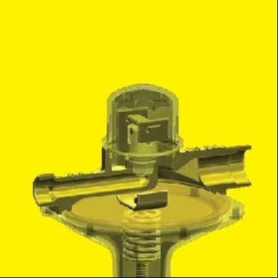
Methven Nefa Pressure Reducing Valves Reference 2x4c59
October 2019 79
Samson Pressure Reducing Valve.pdf 54233h
November 2019 65
Pressure Reducing And Surplussing Valva-spirax-sarco 672p2f
December 2019 52
Pressure Reducing Regulator Fisher Manual Serie 64 6du1a
December 2019 62
Jaksa High-pressure Solenoid Valves 1r2h3a
November 2019 29
Ezr Pressure Reducing Regulator Bulletin En 123624 x6044
December 2019 28More Documents from "Len Salisbury" 153p6r

Hamilton City Wintec Campus Map 2zx6g
January 2022 0
Methven Nefa Pressure Reducing Valves Reference 2x4c59
October 2019 79
Creative Inspire 5.1 5200 Manual 373ig
November 2019 159
W. Elmo Mercer 1958 - The Way That He Loves f275i
December 2021 0
April 2022 0