Mx3ipg2a-rotor Ground Fault 3i3s15
This document was ed by and they confirmed that they have the permission to share it. If you are author or own the copyright of this book, please report to us by using this report form. Report 3b7i
Overview 3e4r5l
& View Mx3ipg2a-rotor Ground Fault as PDF for free.
More details w3441
- Words: 631
- Pages: 2
Modulex3 Line
MX3IPG2A
Numerical integrated generator protection (Rotor and auxiliary protection):
Protection functions • Rotor earth fault detection based on injection of a.c. low voltage (accessory X2/IPG2A) between the rotor winding of the protected synchronous machine and ground. • Two independent time thresholds measuring the resistance of the earth fault (R<; R<<). • One independent time overcurrent (I>) measuring the circulating current. • Monitoring of the injected voltage. • Dedicated input for wide range d.c. voltage measurement (d.c. auxiliary voltage monitoring, d.c. current measurement on Shunt). • Two independent time d.c. undervoltage (U -<, U - <<). • Two independent time d.c. overvoltage (U - >, U - >>). • Starting outputs (alarm), instantaneous or delayed. • Two setting groups, switch in operation: from HMI, Digital input or Communication. Measurement functions • Injected voltage. • Circulating current. • Max. circulating current. • Earth fault resistance. • D.C. voltage.
64R - 27 d.c. - 59 d.c.
Recording functions • Record of the last fault (last eight) with date and time (YY/MM/DD hh:mm:ss.mmm) and fault values. • Record of the logical status change (last 32) included thresholds, digital inputs, timers, with date and time (YY/MM/DD hh:mm:ss.mmm) • Disturbance recording with record of all input signals and correlated logical status; possibility to choose the cause determining trigger and define the recording time before and after trigger (for a total recording time of 2.5 s). • Record on counters and LED's. Monitoring and control: digital inputs and outputs • 3 freely assignable inputs (controls, blocks, setting group switch). • 6 output relays one of which is for diagnostic and 5 freely assignable to the functions.
Communication • Rear serial port for connection to Lonworks™ network at 1.25 Mbit/s. • Alternatively: serial port RS485 and Modbus protocol Human Machine Interface • Local HMI with keyboard, backlit LCD display, 12 LED's, 8 of which are freely assignable to the functions. • Local HMI by PC connected to the front serial port. • Remote interface by the Local Area Network.
Characteristics Generator rated excitation voltage ≤1000 V d.c. Excitation circuit to ground capacitance ≤5 µF Injected voltage (X2/IPG2A) 40 V
Output relay s Rated current 5A Breaking 0.3 A @ 110 Vd.c., L/R=40 ms Make and carr y 30 A for 0.5 s Mechanical life 106 operations
Rated frequency fn
Standards EN 60255-6 IEC 255
50/60 Hz
R< 200 to 4000 ohm Independent time 0.05 to 600 s R<< 200 to 4000 ohm Independent time 0.05 to 600 s I> 10 to 100 mA Independent time 0.05 to 600 s D.C. voltage measurement ranges selectable by internal bridges. Measur. Continuous Rated range withstand voltage 0 to 0.5 V 6 V 0.03 to 0.3 V 0 to 5 V 40 V 0.3 to 3 V 0 to 50 V 150 V 3 to 30 V 0 to 500 V 500 V 30 to 300 V Input resistance 0 to 0.5 V 0 to 5 V 0 to 50 V 0 to 500 V
1 Kohm 10 Kohm 100 Kohm 1000 Kohm
U- < Independent time U - << Independent time
0.5 to 1.2 Un 0.02 to 600 s 0.5 to 1.2 Un 0.02 to 600 s
U-> Independent time U ->> Independent time
0.5 to 1.2 Un 0.02 to 600 s 0.5 to 1.2 Un 0.02 to 600 s
Auxiliary supply of MX3IPG2A Uaux: 19 to 100 Vd.c. or: 19 to 72 Va.c. Uaux: 64 to 300 Vd.c. or: 64 to 275 Va.c. Burden: 5 W/10 W d.c. 10VA/20VA a.c. Auxiliary supply of X2/IPG2A Uaux: 24 to 240 Va.c. Frequency: 45 to 65 Hz Burden: <5 VA.
ALSTOM FIR S.p.A. - via Viscardi,5 - 24016 SAN PELLEGRINO T. - BG - ITALIA Tel. ++39 0345 28111 - Fax ++39 0345 22590 - Telex 301152 FIR I - E-mail: [email protected]
Related Documents 3m3m1z

Ground Fault Current Calculation 6c582b
December 2019 72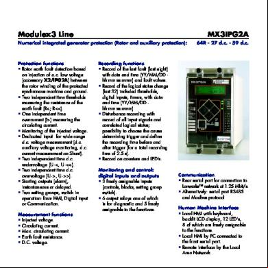
Mx3ipg2a-rotor Ground Fault 3i3s15
February 2022 0
Dc Ground Fault Detection Explanation 5z145
October 2019 54
Rotor Ground Fault Protection Of Generator.pdf 45750
November 2019 28
Murray Loop Test To Locate Ground Fault 5og6j
December 2019 63