Oteva 70 En 4t713c
This document was ed by and they confirmed that they have the permission to share it. If you are author or own the copyright of this book, please report to us by using this report form. Report 3b7i
Overview 3e4r5l
& View Oteva 70 En as PDF for free.
More details w3441
- Words: 7,510
- Pages: 20
Technical Product Information
Spring wire for applications with high performance demands
Suzuki Garphyttan has produced wire since 1906. Since 1927 the main product is oiltempered valve spring wire for the automotive industry. During the years others specialty wires such as stainless round wire, flatrolled and shaped wire in carbon, low alloyed and stainless material, have been added to the product program. We have acquired extensive knowledge and experience of steel grades, efficient manufacturing and quality control which is crucial to the properties of the finished product. Large resources are invested in research concerning improved properties of our products and improved manufacturing processes, enabling Suzuki Garphyttan to be world leader in the manufacturing of spring wire. The main focus is spring wire for combustion engines (valve and transmission springs, piston rings, compression rings, fuel injection springs) and other automotive applications.
Coiling properties Defect free surfaces, narrow dimensional and tensile strength tolerances are important in achieving the best properties for spring coiling. Each wire is continuously controlled during the entire manufacturing – from wire rod to the finished product – according to a specific control plan. Certified quality Suzuki Garphyttan has a Quality Management System certified according to the International Standard for Quality ISO TS 16949. Our main wire rod suppliers also have Quality Management Systems certified by a third party according to ISO 9001 as a minimum and are also regularly audited by Suzuki Garphyttan. Technical We are prepared to assist you in utilizing modern materials for maximum performance. For us it is obvious and necessary to be at the front, to serve our customers, discussing problems and areas for development in existing as well as new products. Environmental awareness Our goal is to manufacture high quality products without any negative effects on the environment. We are continuously improving our manufacturing processes to improve both internal and external environment. Before new investments are made, special consideration is given to environmental solutions. We are certified according to ISO 14001. For more information regarding different elements in our products we recommend the database IMDS ”International Material Data System” where each element is named with a separate CAS-No. See the following Internet address: www.mdsystem.com.
March 2011 This information is subject to change (design, dimensions, technical data, etc) without prior notice.
Specialty steel spring wire for applications with high performance requirements
Oil tempered spring wire
March 2011 This information is subject to change (design, dimensions, technical data, etc) without prior notice.
OTEVA® oil tempered valve spring wire For valve springs in combustion engines as well as for transmission and crankshaft damper springs subjected to extreme fatigue. OTEVA® grades cover different demands of high performance in tensile strength and fatigue life.
High quality oil tempered wire
Our valve spring wire grades differ from each other in of chemical, mechanical and technical properties as well as required surface finish with regard to surface depth and decarburization levels. Oil tempered wire is also manufactured with egg or elliptical cross sections. Profiled cross sections give the advantage of optimum distribution of stresses in a spring (see fig.).
KD oil tempered clutch and transmission spring wire For use in clutch springs of different types with various performance demands. KD is an oil tempered wire with good dynamical characteristics, excellent coiling characteristics and good relaxation properties.
Stress distribution in transversal section comparing round (picture to the right) and egg shaped (picture to the left) wire respectively.
STATO oil tempered spring wire An oil tempered wire grade used for springs subjected to static stress or moderate fatigue. STATO is available in different types of steel demanding ultimate tensile strength, and relaxation properties comparable to the OTEVA® grades. Good coiling characteristics make STATO an excellent alternative to cold drawn spring wire.
Chemical composition, approximate values in % Our grades
C
Si
Mn
P max.
S max.
Cr
V
Ni
OTEVA® 90 SC
0.60
2.00
0.85
0.020
0,020
0.95
0.10
0.30
OTEVA® 75 SC
0.60
1.47
0.70
0.020
0.020
0.67
0.15
–
OTEVA® 70 SC
0.53
1.47
0.70
0.025
0.020
0.67
–
–
70 KD
0.53
1.47
0.70
0.025
0.020
0.67
–
–
STATO 70
0.53
1.47
0.70
0.025
0.025
0.67
–
–
Nearest equivalent standards Our grades
EN 10270-2
SIS
ASTM
B.S.
JIS
OTEVA® 90 SC
–
–
–
–
–
OTEVA® 75 SC
VDSiCrV
–
–
–
–
OTEVA® 70 SC
VDSiCr
142090-05
A 877
2803 685A55HD
JIS G 3561 SWOSC-V
70 KD
TDSiCr
142090-05
A 401
2803 685A55ND
–
STATO 70
FDSiCr
142090-05
A 401
2803 685A55HS
JIS G 3568 SWOSC-B
March 2011 This information is subject to change (design, dimensions, technical data, etc) without prior notice.
Eddy Current continuous surface testing
Eddy Current testing is carried out on material with high demands on surface quality. EC-testing is performed in Circograph and Defectomat equipment. The different levels of EC-testing are indicated in the steel grade designations in the table below.
Steel grade designations OTEVA® 90 SC RD40 S OTEVA® 75 SC RD40 S OTEVA® 70 SC RD40 S OTEVA® 70 SC S
(*)
OTEVA® 70 SC
(*)
70 KD R60 70 KD
(*)
STATO 70
(*)
SC
= Super Clean
R
= Circograph tested
RD
= Circograph + Defectomat tested
40, 60 = Defect depth levels in µm S
Suzuki Garphyttan uses the most advanced Eddy Current testing equipment available on the market. Experience from many years of surface testing in efficient continuous testing lines is a guarantee for high quality spring wire.
March 2011 This information is subject to change (design, dimensions, technical data, etc) without prior notice.
= Shaved
Continuous testing of surface defects is performed as standard in sizes from 2.20 – 6.00 mm. Other sizes from 2.00 up to 6.20 mm can be agreed upon. Grades indicated with (*) refer to material outside the size range 2.20 – 6.00 mm, or grades not requiring EC-testing.
Delivery forms Oil tempered spring wire Delivery forms Spool/Coil diameter Inner Outer diam. diam. min. mm max. mm
Coil/Spool weight
Wire sizes mm
Type
Code
0.50 – 1.00 0.50 – 2.10
Plastic spool Metal spool
S4610 S6520
314 400
460 700
1.10 – 2.50 0.80 – 2.50 0.80 – 2.50
Coils/Carrier No 1 Coils/Carrier No 2 Coils/Wooden Box
RU0004 RM0004 RM0021 RM0024 RM0025
450 450 450 450 450
700 700 700 700 700
2.00 – 3.00
Coils/Carrier No 3
RM0006 RU0006 RU0019 RU0021*
720 720 720 720
1200 1200 1200 1200
225 450 450 450
2.00 – 4.00
Coils/Wooden Box
RM0021 RM0022 RM0023
720 720 720
1200 1200 1200
225 225 225
2.00 – 3.00
Coils/Carrier No 4
RU0011 RU0020 RU0022*
1070 1070 1070
1500 1500 1500
900 900 900
> 3.00 – 6.50 Coils/Carrier No 5
RU0012 RU0014*
1070 1070
1500 1500
1800 1800
1350
1650
500
> 6.50 – 14.00 Coils**
abt. kg
40 125/ 250
80/ 80/ 80/ 80/
250 170 170 170 170
* RU0014, RU0021 and RU0022 has VCI plastic cover, oversea transport. ** Sizes > 6.50 – 14.00 mm in coils in unshaved condition subcontracted.
Packing
The packings for the different delivery forms can be seen in the next page. Standard packing alternatives (others can be delivered on special request): Plastic and metal spool covered with paper - on EUR-pallet (S-codes) Coil covered with plastic hood - on carrier (RU-codes) Coil covered with VCI plastic hood - on carrier (RU-codes) oversea transport. Coils separately wrapped with paper - on carrier (RM-codes) Coils separately wrapped with paper - in wooden boxes (RM-codes) Wire sizes 6.50 – 10.00 mm is subcontracted and the sales is organized from our German office. Packaging materials used are only those which can be recycled, such as paper and polyethylene.
March 2011 This information is subject to change (design, dimensions, technical data, etc) without prior notice.
Delivery forms Oil tempered spring wire Carriers Surface: galvanized Type
Delivery form Code
Carrier 1
RU0004
800
1200 1000
420
17
700
Carrier 2
RM0004
800
1200 1000
540
17
300
Carrier 3
RM0006 RU0006 RU0019 RU0021
800 800 800 800
1200 1200 1200 1200
900 900 900 900
720 720 720 720
18 18 18 18
1200 1200 1200 1200
Carrier 4
RM0011 RU0011 RU0020 RU0022
1160 1160 1160 1160
1530 1530 1530 1530
960 960 960 960
1070 1070 1070 1070
31 31 31 31
1200 1200 1200 1200
Carrier 5
RU0012 RU0014
1160 1160
1530 1200 1070 1530 1200 1070
42 42
1800 1800
Size, mm A B
C
D
Tara weight abt. kg
Max weight abt. kg
Spools Colour: black/green Type
Delivery form Size, mm Code A B
Plastic
S4610 460
105
319
91
305
Metal
S6520 695
314
400
270
33
C
D
E
Tara weight abt. kg
1.8 26
Max. weight abt. kg
40 275
EUR-pallet Spools Type
Delivery form Code
1
SP6520
800
1200
150
26
275
750
2
SP4611
800
1200
340
34
40
500
3
SP4612
800
1200
540
42
40
750
4
SP4613
800
1200
740
50
40
1000
Size, mm Width Length
Height
Tara weight abt. kg
Spool weight abt. kg
Weight abt. kg
Packing of plastic and metal spools on EUR-pallet. Max. weight 1000 kg. Wooden boxes Boxes for coils Type
Delivery form Code
Outer size, mm Width Length Height
Tara weight abt. kg
Coil weight abt. kg
Weight abt. kg
Box 1 RM0021
1110
1150
1000
78
225/450 1000
Box 2 RM0022
1110
1150
620
57
225/450
500
Box 3 RM0023
1110
1150
430
48
225/450
250
Box 4 RM0024
800
850
940
52
80/170
500
Box 5 RM0025
800
850
580
36
80/170
250
Packing of wrapped coils with wire sizes > 2.50 mm is usually carried out in boxes No. 1 – 3. Coils with wire sizes < 2.50 mm in boxes No. 1, 4 – 5.
March 2011 This information is subject to change (design, dimensions, technical data, etc) without prior notice.
OTEVA® 90 SC is a Super Clean (SC) steel.
OTEVA® 90 SC
OTEVA® 90 SC is especially intended for the manufacture of valve springs and other springs requiring extremely high fatigue properties and good relaxation properties at increased working temperatures.
Oil tempered SiCrV+Ni-alloyed high tensile valve spring wire for surface nitriding
Manufactured as standard in sizes from 2.00 mm to 6.00 mm Ø in shaved condition. Other wire sizes on request. We also produce OTEVA® 90 SC in egg (ovate) or elliptical shape (corresponding to round cross section 2.50 mm to 6.00 mm). Chemical composition C %
Si %
Mn %
P max. %
S max. %
Cr %
V %
Ni %
0.50 – 0.70
1.80 – 2.20
0.70 – 1.00
0.020
0.020
0.85 – 1.05
0.05 – 0.15
0.20 – 0.40 4)
Physical properties Tolerance ± mm
Tensile strength 2 N/mm
Reduct. of area min. %
Torsions l=300 mm, min. revs.
2.00 – 2.50
0.020
2180 – 2280
45
5
>2.50 – 3.20
0.020
2130 – 2230
45
5
>3.20 – 4.00
0.025
2080 – 2180
45
4
>4.00 – 5.00
0.025
2030 – 2130
45
3
>5.00 – 5.60
0.030
1980 – 2080
40
3
>5.60 – 6.00
0.035
1980 – 2080
40
3
1)
Size range mm
2)
3)
1)
Other wire sizes on request.
2)
Ovality, i. e. the difference between the largest and smallest dimension of a cross section, is maximum half the tolerance range.
3)
Conversion from tensile strength to hardness values can be calculated in standard ISO EN 18265.
4)
Torsion test is carried out for assessing deformability. The fracture of the torsion test piece shall be smooth and perpendicular to the wire axis. The rupture shall show no longitudinal cracks.
Yield point The proof stress Rp0.2 is min. 0.8 x tensile strength of the wire. The proof stress will rise above 0.9 x tensile strength after stress relieving the springs. The tensile strength Rm 2 within one coil does not vary more than 50 N/mm . E and G modulus Modulus of elasticity, E: Modulus of shear, G:
About 206 kN/mm2 About 79.5 kN/mm2
Surface condition Non-destructive testing In the standard size range 2.20 - 6.00 mm the wire is tested continuously in Eddy Current equipment to a surface level of > 40 microns. Other wire sizes on request. End sample test The wire is end sample tested by means of etch testing and binocular inspection as well as microscopical inspection of the material structure. Decarburization and surface defect depths Max. permissible depth of partial surface decarburization and surface defects, 0.5% x wire diameter. No complete decarburization allowed. Non-metallic inclusions The presence of non-metallic inclusions in the wire rod is inspected for every heat in accordance with the Suzuki Garphyttan method (or alternative max. T-method).
Our critera for releasing wire rod material for valve spring wire are the following; For wire rod samples: Inclusion size max. 15 µm in surface area. Inclusion size, surface Max. number of inclusions
5–10 50
> 10–15
>15 µm
7
0
As stated by IVSWMA*, it is likely to find occasional inclusions in valve spring quality steel of a size larger than 15µm. * IVSWMA: International Valve Spring Wire Manufacturers Association
Heat treatment As soon as possible after coiling, the springs should be stress relieved. Depending on nitriding temperature used later in the valve spring manufacturing process, this temperature may be decreased. Hot presetting After shot peening, the springs should be hot preset or stress relieved. In order to reach optimum fatigue and relaxation properties, the springs must be preset at an appropriate stress. Delivery forms See separate sheet.
March 2011 This information is subject to change (design, dimensions, technical data, etc) without prior notice.
OTEVA® 90 SC Oil tempered SiCrV+Ni-alloyed high tensile valve spring wire for surface nitriding Soft shot peening Before the nitriding process a soft shot peening process shall be applied in order to remove the oxide layer on the spring wire surface.
Spring conditions for fatigue and relaxation tests (specially designed test spring) Diagrams 1 and 2:
Nitriding Springs of OTEVA® 90 SC should be nitrided to obtain optimum fatigue and relaxation properties. Our recommendation is gas nitriding.
Wire diameter Spring index Stress relieving Temperature
Shot peening In order to obtain optimum fatigue properties, the process time should be adjusted to get a complete treatment. Size of shots should be adapted to wire dimension, pitch and shot peening equipment. For nitrided springs with an extremely hard surface zone, it is important to use a shot peening media with high hardness. Shot peening of the inside of the spring coils is particularly critical. Relaxation and fatigue properties In diagram 1 the fatigue properties of this grade are illustrated in a Goodman-diagram, based on a special test spring design.
Final stress Tau (corr.) 2 6 N/mm Number of cycles: 25 x 10
Time
450 ±5 °C (840 ±10 °F) min. 420 °C (790 ±10 °F) for nitriding 30 minutes
Soft shot peened Speed Time Shot size
20-30 m/s 5 min 0,8 mm
Nitriding Temperature Time Aim for surface hardness Aim for core hardness Compound (white) layer
Gas nitriding 450-470°C 5-20 hours Min. 800 Hv Min. 560 Hv Max. 1 µm.
Shot peening (double shot peening for nitrided springs) 1st treatment
Diagram 2 shows the relaxation properties (loss of load) of springs made from OTEVA® 90 SC wire subjected to static compression at different temperatures, nitrided/not nitrided. For further technical , please Suzuki Garphyttan.
Ø 3,85 mm 6
2nd treatment Hardness of shot-peening grit (shot) Aim for Almen arc-height Hot presetting (theoretically set) Temperature Time
Initial stress Tau (corr.) 2 N/mm
Speed 56 m/sec. for 20 minutes, size of shots 0.6 mm Speed 30 m/sec. for 10 minutes, size of shots 0.25 mm min. 800 Hv 0.55-0.60 mm 2
1500 N/mm (nitrided springs) 2 1300 N/mm (not nitrided springs) 200°C (max. 250°C) 10 minutes
Nitrided Not nitireded
Time of test:
24 h
2
Initial stress Tau (corr.) N/mm
Loss of load, %
Diagram 1 - Fatigue properties as nitrided/not nitrided.
Diagram 2 - Relaxation properties, nitrided/not nitrided springs.
March 2011 This information is subject to change (design, dimensions, technical data, etc) without prior notice.
OTEVA® 75 SC is a Super Clean (SC) steel.
OTEVA® 75 SC
OTEVA® 75 SC is especially intended for the manufacture of valve springs and other springs requiring high fatigue properties and good relaxation properties at moderately increased working temperatures.
Oil tempered SiCrV-alloyed high tensile valve spring wire
Manufactured as standard in sizes from 2.00 mm to 6.00 mm Ø in shaved condition. We also produce OTEVA® 75 SC in egg (ovate) or elliptical shape (corresponding to round cross section 2.50 mm to 6.00 mm). Chemical composition C %
Si %
Mn %
P max. %
S max. %
Cr %
V %
0.50 – 0.70
1.20 – 1.65
0.50 – 0.80
0.020
0.020
0.50 – 1.00
0.05 – 0.20
Physical properties 4)
1)
Size range mm
2)
3)
Torsions l=300 mm, min. revs.
Tolerance ± mm
Tensile strength 2 N/mm
Reduct. of area min. %
2.00 – 2.50
0.020
2110 – 2210
45
5
>2.50 – 3.20
0.020
2060 – 2160
45
5
>3.20 – 4.00
0.025
2010 – 2110
45
4
>4.00 – 5.00
0.025
1960 – 2060
45
3
>5.00 – 5.60
0.030
1910 – 2010
40
3
>5.60 – 6.00
0.035
1910 – 2010
40
3
1)
Other wire sizes on request.
2)
Ovality, i. e. the difference between the largest and smallest dimension of a cross section, is maximum half the tolerance range.
3)
Conversion from tensile strength to hardness values can be calculated in standard ISO EN 18265.
4)
Torsion test is carried out for assessing deformability. The fracture of the torsion test piece shall be smooth and perpendicular to the wire axis. The rupture shall show no longitudinal cracks.
Yield point The proof stress Rp0.2 is min. 0.9 x tensile strength of the wire. The tensile strength Rm within one coil does not vary more 2 than 50 N/mm .
Non-metallic inclusions The presence of non-metallic inclusions in the wire rod is inspected for every heat in accordance with the Suzuki Garphyttan method (or alternative max. T-method).
E and G modulus Modulus of elasticity, E: Modulus of shear, G:
Our criteria for releasing wire rod material for valve spring wire are the following; For wire rod samples: Inclusion size max. 15 µm in surface area.
About 206 kN/mm2 About 79.5 kN/mm2
Surface condition Non-destructive testing In the standard size range 2.20 - 6.00 mm the wire is tested continuously in Eddy Current equipment to a surface level of > 40 microns. Other wire sizes on request. End sample test The wire is end sample tested by means of etch testing and binocular inspection as well as microscopical inspection of the material structure. Decarburization and surface defect depths Max. permissible depth of partial surface decarburization and surface defects, 0.5% x wire diameter. No complete decarburization allowed.
Inclusion size, surface Max. number of inclusions
5–10 50
> 10–15
>15 µm
7
0
As stated by IVSWMA*, it is likely to find occasional inclusions in valve spring quality steel of a size larger than 15µm. * IVSWMA: International Valve Spring Wire Manufacturers Association
Delivery forms See separate sheet.
March 2011 This information is subject to change (design, dimensions, technical data, etc) without prior notice.
OTEVA® 75 SC Oil tempered SiCrV-alloyed high tensile valve spring wire
Heat treatment As soon as possible after coiling, the springs should be stress relieved. Shot peening In order to obtain optimum fatigue properties, the process time should be adjusted to get a complete treatment. Size of shots should be adapted to wire dimension, pitch and shot peening equipment. Shot peening of the inside of the spring coils is particularly critical. Hot presetting After shot peening, the springs should be hot preset or stress relieved. In order to reach optimum fatigue and relaxation properties, the springs must be preset at an appropriate stress. Relaxation and fatigue properties In diagram 1 the fatigue properties of this grade are illustrated in a Goodman-diagram, based on a special test spring design. Diagram 2 shows the relaxation properties (loss of load) of springs made from OTEVA® 75 SC wire subjected to static compression at different temperatures.
Spring conditions for fatigue and relaxation tests (specially designed test spring) Diagram 1 and 2: Wire diameter Spring index
Ø 4.00 mm 6
Stress relieving Temperature Time
420 ±5°C (790 ±10 °F) 30 minutes
Shot peening (double shot peening) 1st treatment 2nd treatment Hardness of Shot-peening grit (shot): Aim for Almen arc-height Hot presetting (theoretically set) Temperature Time
Speed 56 m/sec. for 20 minutes, size of shots 0.8 mm Speed 30 m/sec. for 10 minutes, size of shots 0.8 mm 610-670 Hv Min 0.45 mm 2
1300 N/mm
200°C (max. 250°C) 10 minutes
For further technical , please Suzuki Garphyttan.
Final stress Tau (corr.) 2 N/mm
Number of cycles:
Initial stress Tau (corr.) 2 N/mm
6
25 x 10
24 h
Loss of load, %
2
Initial stress Tau (corr.) N/mm
Diagram 1 - Fatigue properties
Time of test:
Diagram 2 - Relaxation properties
March 2011 This information is subject to change (design, dimensions, technical data, etc) without prior notice.
OTEVA® 70 SC is a Super Clean (SC) steel. OTEVA® 70 SC is especially intended for the manufacture of valve springs and other springs requiring high fatigue properties and good relaxation properties at moderately increased working temperature.
OTEVA® 70 SC Oil tempered SiCr-alloyed valve spring wire
The wire is manufactured in sizes from 0.70 mm to 6.50 mm Ø in shaved or unshaved condition (6.50 – 14.00 mm in unshaved condition subcontracted). We are also producing OTEVA® 70 SC in egg (ovate) or elliptical shape (corresponding to round cross section 2.50 mm to 6.00 mm). Chemical composition C %
Si %
Mn %
P max %
S max %
Cr %
0.50 – 0.60
1.20 – 1.60
0.50 – 0.80
0.020
0.020
0.50 – 0.80
Physical properties 4)
1)
Size range mm
2)
3)
Torsions l=300 mm, min. revs.
Tolerance ± mm
Tensile strength N/mm2
Reduct. of area min. %
0.70 – 0.80
0.010
2080 – 2210
–
6
>0.80 – 1.30
0.015
2080 – 2210
50
5
>1.30 – 1.40
0.015
2080 – 2210
50
5
>1.40 – 1.60
0.020
2080 – 2210
50
5
>1.60 – 2.00
0.020
2010 – 2160
50
5
>2.00 – 2.50
0.020
1960 – 2060
50
5
>2.50 – 3.00
0.020
1910 – 2010
50
4
>3.00 – 3.20
0.020
1910 – 2010
45
4
>3.20 – 3.50
0.025
1910 – 2010
45
4
>3.50 – 4.50
0.025
1860 – 1960
45
4
>4.50 – 5.00
0.025
1810 – 1910
45
3
>5.00 – 5.60
0.030
1810 – 1910
40
3
>5.60 – 6.50
0.035
1760 – 1860
40
3
1)
Smaller wire sizes (from 0.50 mm) on request.
2)
Ovality, i. e. the difference between the largest and smallest dimension of a cross section, is maximum half the tolerance range.
3)
Conversion from tensile strength to hardness values can be calculated in standard ISO EN 18265.
4)
Torsion test is carried out for assessing deformability. The fracture of the torsion test piece shall be smooth and perpendicular to the wire axis. The rupture shall show no longitudinal cracks.
Yield point The proof stress Rp0.2 is min. 0.9 x tensile strength of the wire. The tensile strength Rm within one coil does not vary more 2 than 50 N/Mm . E and G modulus Modulus of elasticity, E: About 206 kN/mm2 2 Modulus of shear, G: About 79.5 kN/mm Surface condition Non-destructive testing In the standard size range 2.20 - 6.00 mm the wire is tested continuously in Eddy Current equipment to a surface level of > 40 microns. Other wire sizes on request. End sample test The wire is end sample tested by means of etch testing and binocular inspection as well as microscopical inspection of the material structure.
Decarburization and surface defect depths Max. permissible depth of partial surface decarburization and surface defects, 1.0% x wire diameter. In shaved condition 0.5% x d. No complete decarburization allowed. The presence of non-metallic inclusions in the wire rod is inspected for every heat in accordance with the Suzuki Garphyttan method (or alternative max. T-method). Our criteria for releasing wire rod material for valve spring wire are the following; For wire rod samples: Inclusion size max. 15 µm in surface area. Inclusion size, surface Max. number of incl.
5–10
>10–15
>15 µm
50
7
0
As stated by IVSWMA*, it is likely to find occasional inclusions in valve spring quality steel of a size larger than 15µm. * IVSWMA: International Valve Spring Wire Manufacturers Association
March 2011 This information is subject to change (design, dimensions, technical data, etc) without prior notice.
OTEVA® 70 SC Oil tempered SiCr-alloyed valve spring wire
Delivery forms See separate sheet.
Spring conditions for fatigue and relaxation tests (specially designed test spring) Diagram 1 and 2:
Heat treatment As soon as possible after coiling, the springs should be stress relieved. Shot peening In order to obtain optimum fatigue properties, the process time should be adjusted to get a complete treatment. Size of shots should be adapted to wire dimension, pitch and shot peening equipment. Shot peening of the inside of the spring coils is particularly critical. Hot presetting After shot peening, the springs should be hot preset or stress relieved. In order to reach optimum fatigue and relaxation properties, the springs must be preset at an appropriate stress.
Wire diameter Spring index
Ø 4,00 mm 6
Stress relieving Temperature Time
420 ±5°C (790 ±10 °F) 30 minutes
Shot peening Hardness of Shot-peening grit (shot): Aim for Almen arc-height Hot presetting (theoretically set) Temperature Time
Speed 48 m/sec. for 20 minutes, size of shots 0.8 mm 610-670 Hv Min. 0.40-0.45 mm 2
1200 N/mm
200°C (max. 250°C) 10 minutes
Relaxation and fatigue properties In diagram 1 the fatigue properties of this grade are illustrated in a Goodman-diagram, based on a special test spring design. Diagram 2 shows the relaxation properties (loss of load) of springs made from OTEVA® 70 SC wire subjected to static compression at different temperatures. For further technical , please Suzuki Garphyttan.
Final stress Tau (corr.) 2 N/mm Number of cycles:
Initial stress Tau (corr.) 2 N/mm
6
25 x 10
Time of test:
24 h
2
Initial stress Tau (corr.) N/mm
Loss of load, %
Diagram 1 - Fatigue properties
Diagram 2 - Relaxation properties
March 2011 This information is subject to change (design, dimensions, technical data, etc) without prior notice.
OTEVA 76 SC is a Super Clean (SC) steel.
OTEVA® 76 SC
OTEVA 76 SC is especially intended for the manufacture of valve springs and other springs requiring high fatigue properties and good relaxation properties at moderately increased working temperatures.
Oil tempered SiCrV-alloyed high tensile valve spring wire Only manufactured in USA and China
Manufactured as standard in sizes from 2.00 mm to 6.00 mm Ø in shaved condition. We also produce OTEVA 76 SC in egg (ovate) or elliptical shape (corresponding to round cross section 2.50 mm to 6.00 mm).
Chemical composition C %
Si %
Mn %
P max. %
S max. %
Cr %
V %
Ni %
0.50 – 0.70
1.20 – 1.65
0.50 – 0.90
0.020
0.020
0.50 – 1.00
0.05 – 0.20
0.15 – 0.50
Physical properties 4)
1)
Size range mm
2)
3)
Torsions l=300 mm, min. revs.
Tolerance ± mm
Tensile strength 2 N/mm
Reduct. of area min. %
2.00 – 2.50
0.020
2110 – 2210
45
5
>2.50 – 3.20
0.020
2060 – 2160
45
5
>3.20 – 4.00
0.025
2010 – 2110
45
4
>4.00 – 5.00
0.025
1960 – 2060
45
3
>5.00 – 5.60
0.030
1910 – 2010
40
3
>5.60 – 6.00
0.035
1910 – 2010
40
3
1)
Other wire sizes on request.
2)
Ovality, i. e. the difference between the largest and smallest dimension of a cross section, is maximum half the tolerance range.
3)
Conversion from tensile strength to hardness values can be calculated in standard ISO EN 18265.
4)
Torsion test is carried out for assessing deformability. The fracture of the torsion test piece shall be smooth and perpendicular to the wire axis. The rupture shall show no longitudinal cracks.
Yield point The proof stress Rp0.2 is min. 0.9 x tensile strength of the wire. The tensile strength Rm within one coil does not vary more 2 than 50 N/mm .
Non-metallic inclusions The presence of non-metallic inclusions in the wire rod is inspected for every heat in accordance with the Suzuki Garphyttan method (or alternative max. T-method).
E and G modulus Modulus of elasticity, E: Modulus of shear, G:
Our criteria for releasing wire rod material for valve spring wire are the following; For wire rod samples: Inclusion size max. 15 µm in surface area.
2
About 206 kN/mm About 79.5 kN/mm2
Surface condition Non-destructive testing In the standard size range 2.20 - 6.00 mm the wire is tested continuously in Eddy Current equipment to a surface level of > 40 microns. Other wire sizes on request. End sample test The wire is end sample tested by means of etch testing and binocular inspection as well as microscopical inspection of the material structure. Decarburization and surface defect depths Max. permissible depth of partial surface decarburization and surface defects, 0.5% x wire diameter. No complete decarburization allowed.
Inclusion size, surface Max. number of inclusions
5–10 50
> 10–15
>15 µm
7
0
As stated by IVSWMA*, it is likely to find occasional inclusions in valve spring quality steel of a size larger than 15µm. * IVSWMA: International Valve Spring Wire Manufacturers Association
Delivery forms Please site: South Bend USA or Suzhou China
March 2011 This information is subject to change (design, dimensions, technical data, etc) without prior notice.
OTEVA® 76 SC Oil tempered SiCrV-alloyed high tensile valve spring wire
Heat treatment As soon as possible after coiling, the springs should be stress relieved. Shot peening In order to obtain optimum fatigue properties, the process time should be adjusted to get a complete treatment. Size of shots should be adapted to wire dimension, pitch and shot peening equipment. Shot peening of the inside of the spring coils is particularly critical. Hot presetting After shot peening, the springs should be hot preset or stress relieved. In order to reach optimum fatigue and relaxation properties, the springs must be preset at an appropriate stress. Relaxation and fatigue properties In diagram 1 the fatigue properties of this grade are illustrated in a Goodman-diagram, based on a special test spring design. Diagram 2 shows the relaxation properties (loss of load) of springs made from OTEVA 76 SC wire subjected to static compression at different temperatures.
Spring conditions for fatigue and relaxation tests (specially designed test spring) Diagram 1 and 2: Wire diameter Spring index
Ø 4.00 mm 6
Stress relieving Temperature Time
420 ±5°C (790 ±10 °F) 30 minutes
Shot peening (double shot peening) 1st treatment 2nd treatment Hardness of Shot-peening grit (shot): Aim for Almen arc-height Hot presetting (theoretically set) Temperature Time
Speed 56 m/sec. for 20 minutes, size of shots 0.8 mm Speed 30 m/sec. for 10 minutes, size of shots 0.8 mm 610-670 Hv Min 0.45 mm 2
1300 N/mm
200°C (max. 250°C) 10 minutes
For further technical , please Suzuki Garphyttan.
Final stress Tau (corr.) 2 N/mm
Number of cycles:
Initial stress Tau (corr.) 2 N/mm
6
25 x 10
2
24 h
Loss of load, %
Initial stress Tau (corr.) N/mm
Diagram 1 - Fatigue properties
Time of test:
Diagram 2 - Relaxation properties
March 2011 This information is subject to change (design, dimensions, technical data, etc) without prior notice.
SWOSC-V is a Super Clean (SC) steel. SWOSC-V is especially intended for the manufacture of valve springs and other springs requiring high fatigue properties and good relaxation properties at moderately increased working temperature.
SWOSC-V Oil tempered SiCr-alloyed valve spring wire Only manufactured in China
The wire is manufactured in sizes from 2.00 mm to 6.50 mm Ø in shaved condition We are also producing SWOSC-V in egg (ovate) or elliptical shape (corresponding to round cross section 2.50 mm to 6.00 mm). Chemical composition C %
Si %
Mn %
P max %
S max %
Cr %
0.50 – 0.60
1.20 – 1.60
0.50 – 0.80
0.025
0.020
0.50 – 0.80
Physical properties 4)
Tolerance ± mm
Tensile strength N/mm2
Reduct. of area min. %
Torsions l=300 mm, min. revs.
1.80 – 2.00
0.020
2010 – 2160
50
5
>2.00 – 2.50
0.020
1960 – 2060
50
5
>2.50 – 3.00
0.020
1910 – 2010
50
4
>3.00 – 3.20
0.020
1910 – 2010
45
4
>3.20 – 3.50
0.025
1910 – 2010
45
4
>3.50 – 4.50
0.025
1860 – 1960
45
4
>4.50 – 5.00
0.025
1810 – 1910
45
3
>5.00 – 5.60
0.030
1810 – 1910
40
3
>5.60 – 6.50
0.035
1760 – 1860
40
3
1)
Size range mm
2)
3)
1)
Smaller wire sizes (from 0.50 mm) on request.
2)
Ovality, i. e. the difference between the largest and smallest dimension of a cross section, is maximum half the tolerance range.
3)
Conversion from tensile strength to hardness values can be calculated in standard ISO EN 18265.
4)
Torsion test is carried out for assesing deformability. The fracture of the torsion test piece shall be smooth and perpendicular to the wire axis. The rupture shall show no longitudinal cracks.
Yield point The proof stress Rp0.2 is min. 0.9 x tensile strength of the wire. The tensile strength Rm within one coil does not vary more 2 than 50 N/Mm . E and G modulus Modulus of elasticity, E: About 206 kN/mm2 2 Modulus of shear, G: About 79.5 kN/mm Surface condition Non-destructive testing In the standard size range 2.20 - 6.00 mm the wire is tested continuously in Eddy Current equipment to a surface level of > 40 microns. Other wire sizes on request. End sample test The wire is end sample tested by means of etch testing and binocular inspection as well as microscopical inspection of the material structure.
Decarburization and surface defect depths Max. permissible depth of partial surface decarburization and surface defects, 1.0% x wire diameter. In shaved condition 0.5% x d. No complete decarburization allowed. The presence of non-metallic inclusions in the wire rod is inspected for every heat in accordance with the Suzuki Garphyttan method (or alternative max. T-method). Our criteria for releasing wire rod material for valve spring wire are the following; For wire rod samples: Inclusion size max. 15 µm in surface area. Inclusion size, surface Max. number of incl.
5–10
>10–15
>15 µm
50
7
0
As stated by IVSWMA*, it is likely to find occasional inclusions in valve spring quality steel of a size larger than 15µm. * IVSWMA: International Valve Spring Wire Manufacturers Association
March 2011 This information is subject to change (design, dimensions, technical data, etc) without prior notice.
SWOSC-V Oil tempered SiCr-alloyed valve spring wire
Spring conditions for fatigue and relaxation tests (specially designed test spring) Diagram 1 and 2:
Delivery forms Please site: Suzhou China Heat treatment As soon as possible after coiling, the springs should be stress relieved. Shot peening In order to obtain optimum fatigue properties, the process time should be adjusted to get a complete treatment. Size of shots should be adapted to wire dimension, pitch and shot peening equipment. Shot peening of the inside of the spring coils is particularly critical. Hot presetting After shot peening, the springs should be hot preset or stress relieved. In order to reach optimum fatigue and relaxation properties, the springs must be preset at an appropriate stress.
Wire diameter Spring index
Ø 4,00 mm 6
Stress relieving Temperature Time
420 ±5°C (790 ±10 °F) 30 minutes
Shot peening Hardness of Shot-peening grit (shot): Aim for Almen arc-height Hot presetting (theoretically set) Temperature Time
Speed 48 m/sec. for 20 minutes, size of shots 0.8 mm 610-670 Hv Min. 0.40-0.45 mm 2
1200 N/mm
200°C (max. 250°C) 10 minutes
Relaxation and fatigue properties In diagram 1 the fatigue properties of this grade are illustrated in a Goodman-diagram, based on a special test spring design. Diagram 2 shows the relaxation properties (loss of load) of springs made from SWOSC-V wire subjected to static compression at different temperatures. For further technical , please Suzuki Garphyttan.
Final stress Tau (corr.) 2 N/mm Number of cycles:
Initial stress Tau (corr.) 2 N/mm
6
25 x 10
Time of test:
24 h
2
Initial stress Tau (corr.) N/mm
Loss of load, %
Diagram 1 - Fatigue properties
Diagram 2 - Relaxation properties
March 2011 This information is subject to change (design, dimensions, technical data, etc) without prior notice.
70 KD is especially intended for the manufacture of clutch and transmission springs and similar moderately high fatigue stressed springs. The material has good relaxation properties.
70 KD Oil tempered SiCr-alloyed clutch and transmission spring wire
The wire is manufactured in sizes from 0.70 to 6.50 mm Ø. Chemical composition C %
Si %
Mn %
P max %
S max %
Cr %
0.50 – 0.60
1.20 – 1.60
0.50 – 0.80
0.025
0.020
0.50 – 0.80
Physical properties Torsions 1)
2)
3)
4)
Tolerance ± mm
Tensile strength N/mm2
Reduct. of area
l=300 mm, min. % min. revs.
0.70 – 0.80
0.010
2080 – 2210
–
6
>0.80 – 1.30
0.015
2080 – 2210
50
5
>1.30 – 1.40
0.015
2080 – 2210
50
5
>1.40 – 1.60
0.020
2080 – 2210
50
5
>1.60 – 2.00
0.020
2010 – 2160
50
5
>2.00 – 2.50
0.020
1960 – 2060
50
5
>2.50 – 3.00
0.020
1910 – 2010
50
4
>3.00 – 3.20
0.020
1910 – 2010
45
4
>3.20 – 3.50
0.025
1910 – 2010
45
4
>3.50 – 4.50
0.025
1860 – 1960
45
4
>4.50 – 5.00
0.025
1810 – 1910
45
3
>5.00 – 5.60
0.030
1810 – 1910
40
3
>5.60 – 6.50
0.035
1760 – 1860
40
3
Size range mm
1)
Smaller wire sizes (from 0.50 mm) on request.
2)
Ovality, i. e. the difference between the largest and smallest dimension of a cross section, is maximum half the tolerance range.
3)
Conversion from tensile strength to hardness values can be calculated in standard ISO EN 18265. Torsion test is carried out for assessing deformability. The fracture of the torsion test piece shall be smooth and perpendicular to the wire axis. The rupture shall show no longitudinal cracks.
4)
Yield point The proof stress Rp0.2 is min. 0.9 x tensile strength of the wire. The tensile strength Rm within one coil does not vary more 2 than 60 N/mm . E and G modulus Modulus of elasticity, E: About 206 kN/mm2 Modulus of shear, G: About 79.5 kN/mm2 Surface condition Non-destructive testing In the standard size range 2.20 - 6.00 mm the wire is tested continuously in Eddy Current equipment to a surface level of > 60 microns. Other wire sizes on request. End sample test The wire is end sample tested by means of etch testing and binocular inspection as well as microscopical inspection of the material structure. Decarburization and surface defect depths Max. permissible depth of partial surface decarburization and surface defects, 1.3% x wire diameter. No complete decarburization allowed.
Non-metallic inclusions Max. level 2 according to DIN 50602-M. Corresponding standard: ASTM E-45-A. Heat treatment As soon as possible after coiling, the springs should be stress relieved. Shot peening In order to obtain optimum fatigue properties, the process time should be adjusted to get a complete treatment. Size of shots should be adapted to wire dimension, pitch and shot peening equipment. Shot peening of the inside of the spring coils is particularly critical. Hot presetting After shot peening, the springs should be hot preset or stress relieved. In order to reach optimum fatigue and relaxation properties, the springs must be preset at an appropriate stress. Delivery forms See separate sheet.
March 2011 This information is subject to change (design, dimensions, technical data, etc) without prior notice.
STATO 70 is especially intended for the manufacture of springs exposed to static or moderately high fatigue stresses. The material has good relaxation properties.
STATO 70
The wire is manufactured in sizes from 0.70 mm to 6.50 mm Ø.
Oil tempered SiCr-alloyed spring wire
Chemical composition C %
Si %
Mn %
P max %
S max %
Cr %
0.50 – 0.60
1.20 – 1.60
0.50 – 0.80
0.025
0.025
0.50 – 0.80
Physical properties Size range1) mm
3)
Tolerance2) ± mm
Tensile strength 2 N/mm
Reduct of area min. %
0.70 – 0.80
0.010
2100 – 2250
–
>0.80 – 1.00
0.015
2100 – 2250
50
>1.00 – 1.40
0.020
2100 – 2250
50
>1.40 – 1.60
0.020
2060 – 2210
50
>1.60 – 2.00
0.025
2010 – 2160
50
>2.00 – 2.50
0.025
1970 – 2120
50
>2.50 – 2.70
0.025
1910 – 2060
50
>2.70 – 3.00
0.030
1910 – 2060
50
>3.00 – 3.50
0.030
1910 – 2060
45
>3.50 – 4.00
0.030
1870 – 2020
45
>4.00 – 4.50
0.035
1870 – 2020
45
>4.50 – 5.00
0.035
1830 – 1980
45
>5.00 – 5.60
0.035
1830 – 1980
40
>5.60 – 6.50
0.040
1780 – 1930
40
1) 2) 3)
Smaller wire sizes (from 0.50 mm) on request. Ovality, i. e. the difference between the largest and smallest dimension of a cross section, is maximum half the tolerance range. Conversion from tensile strength to hardness values can be calculated in standard ISO EN 18265.
Yield point The proof stress Rp0.2 is min. 0.9 x tensile strength of the wire. The tensile strength Rm within one coil does not vary more 2 than 70 N/mm . E and G modulus Modulus of elasticity, E: Modulus of shear, G:
About 206 kN/mm2 About 79.5 kN/mm2.
Surface condition End sample test The wire is end sample tested by means of etch testing and binocular inspection as well as microscopical inspection of the material structure. Decarburization and surface defect depths Max. permissible depth of partial surface decarburization and surface defects, 1.5% x wire diameter. No complete decarburization allowed.
Non-metallic inclusions Max. level 2 according to DIN 50602-M. Corresponding standard: ASTM E-45-A. Heat treatment As soon as possible after coiling, the springs should be stress relieved. Shot peening In order to obtain optimum fatigue properties, the process time should be adjusted to get a complete treatment. Size of shots should be adapted to wire dimension, pitch and shot peening equipment. Shot peening of the inside of the spring coils is particularly critical. Hot presetting After shot peening, the springs should be hot preset or stress relieved. In order to reach optimum fatigue and relaxation properties, the springs must be preset at an appropriate stress. Delivery forms See separate sheet.
March 2011 This information is subject to change (design, dimensions, technical data, etc) without prior notice.
Addresses Production Sites
Sales Representatives/Distributors/Re-sellers
Sweden Suzuki Garphyttan AB Bruksvägen 3 SE-719 80 Garphyttan Sweden Tel +46 (0)19 295 100 Fax +46 (0)19 295 101 e-mail [email protected] www.suzuki-garphyttan.com
Albania, Austria, Bosnia-Herzegovina, Bulgaria, Croatia, Czech Republic, Hungary, Macedonia, Romania, SerbiaMontenegro, Slovakia and Slovenia AWS STAHLHANDEL GESELLSCHAFT MBH Feldgasse 2 AT-3422 Hadersfeld Austria Tel +43 2242 5330 Fax+43 2242 5333-30 e-mail [email protected] www.aws.co.at
USA Suzuki Garphyttan Corp. 4404 Nimtz Parkway South Bend, IN 46628 USA Tel +1 574 232 8800 Fax +1 574 232 2565 e-mail [email protected]
Belgium, Luxembourg and Netherlands
China Suzuki Garphyttan (Suzhou) Co. Ltd. Building B, No 6 Longpu Road SIP, Suzhou 215126 P.R. China Tel +86 512 8885 5360 Fax +86 512 8885 5366 e-mail [email protected]
JOOP H BECKER HANDELSONDERNEMING Schaaksport 142 NL-9728 PG Groningen Netherlands Tel +31 651 345 233 Fax+31 505 278 515 e-mail [email protected]
USA Suzuki Garphyttan Corp. 4404 Nimtz Parkway South Bend, IN 46628 USA Tel +1 574 232 8800 Fax +1 574 232 2565 e-mail [email protected] March 2011 This information is subject to change (design, dimensions, technical data, etc) without prior notice.
Related Documents 3m3m1z

Oteva 70 En 4t713c
November 2019 117
En 81-70 20n5p
November 2019 37
Arcelormittal Cofrastra 70 Brochure En 3r2c3y
November 2019 53
Tipografia En Los 70.pdf 506c54
December 2019 50
Schott Ptr 70 Receiver En 2u38r
November 2019 30
Hipercor 70% 7421c
December 2019 69More Documents from "luca" 2e3b20

Come Tradurre Dall'inglese All'italiano 4428
August 2021 0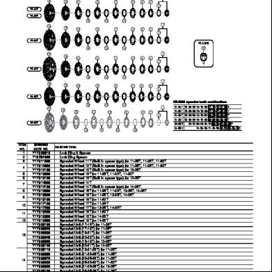
Ev-cs-6800-3602c 6h4x6q
January 2023 0
Forensic - Incident Response Analisys - Computer Forensics Forensic Italian Italiano.pdf 211s56
August 2021 0
Manuale Progettazione Ventilazione Comfort s565i
August 2021 0
Ss 7 4r4q1g
August 2021 0