Ppt Automatic Street Light l4h5m
This document was ed by and they confirmed that they have the permission to share it. If you are author or own the copyright of this book, please report to us by using this report form. Report 3b7i
Overview 3e4r5l
& View Ppt Automatic Street Light as PDF for free.
More details w3441
- Words: 991
- Pages: 26
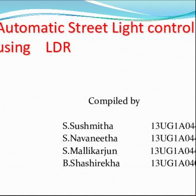
Automatic Street Light control using LDR Compiled by S.Sushmitha S.Navaneetha S.Mallikarjun B.Shashirekha
13UG1A0448 13UG1A0447 13UG1A0449 13UG1A0405
Contents Introduction Existing Method Proposal Method
Block diagram Hardware Requirement Description of Hardware Working
Result Conclusion
Introduction: •
Automatic Street Light Control System Is A Simple Yet Powerful Concept, Which Uses Transistor As A Switch. By Using This System Manual Works Are 100% Removed. It Automatically Switches ON Lights When The Sunlight Goes Below The Visible Region Of Our Eyes. • This Is Done By A Sensor Called Light Dependant Resistor (LDR) Which Senses The Light Actually Like Our Eyes. It Automatically Switches OFF Lights Whenever The Sunlight Comes, Visible To Our Eyes.
Existing Methods: It became essential for people work during nights and
returning back to homes late nights; also increasing crime rate during night times. This can be best achieved by implementing proper LDR based lighting system on Streets.
Proposal Method: Street light controllers are smarter versions of the
mechanical or electronic timers previously used for street light ON-OFF operation. They come with energy conservation options like twilight saving, staggering or dimming. Also many street light controllers come with an astronomical clock for a particular location or a Global Positioning System (GPS) connection to give the best ON-OFF time and energy saving
Block Diagram: LCD 16X2 LINES
POWER SUPPLY Micro controller AT89S52
LDR
STREET LIGHTS
Description of Hardware : LDR: Sensitivity depends on intensity of light. Resistance of LDR decrease with increase in intensity of light and vice-versa.
Resistor: It is a ive component having two terminals that are
used to manage the current flow in the circuit. A current that flows via a resistor is directly proportional to the voltage that appeared into resistor. Two types: (1) Fixed value resistor (2) Variable resistor
(3)IC AT89S52:
IC The CA 3140 is an operational amplifier can
works on supply voltage 4V to 36V & very low input current from 10pA to 1mA. Here, The CA3140 works as a comparator and gives fast response &high speed.
(4) Relays Relays is an electrically operated switch. Current flowing through the coil of the relay creates a
magnetic field which attracts a lever & changes the switch s. It has 3-pin,4-pin,5-pin etc…but we have used 5-pin in our circuit diagram.
Relay offers easy way for LED to indicate a voltage
is present at Relay coil. As no input state, the COM is connected To NC & when operating V is applied to relay coil Gets energized &COM Is now with NO.
(5) BC548 Transistor : It is a general purpose silicon, NPN, bipolar
junction transistor. It is used for amplification & switching purpose. Here, for switching purpose it is biased so that it remains on if there is signal at its base , otherwise it is completely off.
Working of Automatic Street Light Controller Switch Circuit: The working of circuit is very much easy to
understand. In this circuit, we used IC CA3140 which is basically an operational amplifier. Pins 2 and 3 of these IC are used to compare the voltage and give us the output in return i.e. it works as a potential divider in its inverting and non-inverting inputs (pins 2 and 3).
Cont. In this LDR and VR1 form one potential divider which
is used to provide a variable voltage at the inverting input (that is 2) and the second potential divider is built around non-inverting input (pin 3) with the help of R1 and R2 which will grant half of the supply voltage to non inverting pin.
Cont. As we know property of LDR that during the time of
day resistance is low therefore voltage at the inverting input ( IE pin 2) is higher than the voltage at the noninverting input (pin3) hence the output at the pin6 is low so the transistor goes into the cutoff state which means LED or bulb will not glow.
Cont. But in dimness or in night we know that resistance of
LDR is high hence voltage at inverting input pin 2 of the IC CA3140 decreases than the non inverting input pin 3 as a result output pin 6 moves to high state which make transistor to conduct and the LED or bulb associated to it start simmering.
LCD:
LEDs are semiconductor diodes, electronic devices that permit current to flow in only one direction. The
diode is formed by bringing two slightly different materials together to form a PN junction
Result: The sunlight is off the night mode to activated the LDR and street lights will on
The sunlight is on the day mode to activated the LDR and street lights will off
Advantages: No man power required. Simple Construction. Efficient method.
Less Consumption of electrical energy. Less maintenance. Cheap and economical.
APPLICATIONS: Used in street light applications. Garden lights Balcony/Stair case/Parking lightings
Future scope: Wireless is the buzz of communication industry today.
The field of wireless communication is growing leaps and bounds day by day. The main aim of the project is to save the power, by using effectively we can save more power, as we know that there is shortage of power nowadays in everywhere mostly in villages etc. So to overcome that we can provide street lights automatically with the centralized intelligent systems. So in future we can design many more advanced technologies to save power.
Softwares: Soft wares used are: Keil software Express PCB for lay out design
Conclusion: In coming days, this will prove a great boon to the
world, since it will save a lot of electricity of power plants that gets wasted in illuminating the street lights. As the conventional sources are depleting very fast, then it`s time to think of alternatives.
Related Documents 3m3m1z
Ppt Automatic Street Light l4h5m
March 2021 0
Automatic Street Light Controller e392c
December 2019 68
Automatic Street Light Control Project 2r4k5d
November 2019 159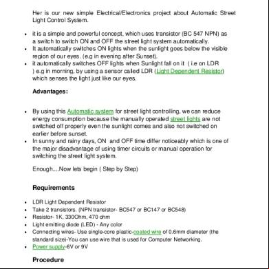
Automatic Street Light Control System 2z2c2p
December 2019 68
Automatic Street Light Project Report 3s1jg
January 2022 0
Automatic Street Light Control Using Ldr 4r362
November 2019 246More Documents from "Amaravathi Gopagani" 2u6x2