Schmitt Trigger 6c4m3h
This document was ed by and they confirmed that they have the permission to share it. If you are author or own the copyright of this book, please report to us by using this report form. Report 3b7i
Overview 3e4r5l
& View Schmitt Trigger as PDF for free.
More details w3441
- Words: 322
- Pages: 4
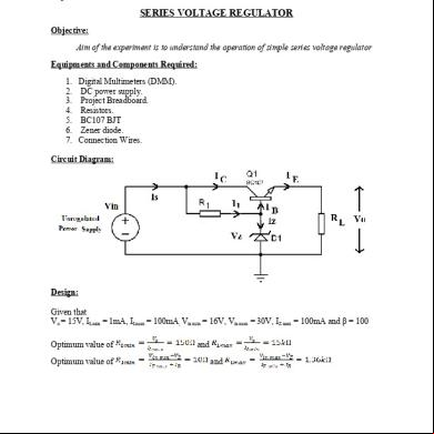
Expt. No. 9 SCHMITT TRIGGER Objective: To study the operation of Schmitt trigger circuit using BJT. Components and equipments required: 1. Oscilloscope (Scope/CRO). 2. Function Generators (FG). 3. DC power supply. 4. Project Breadboard. 5. Resistors. 6. SL100 BJTs / BEL100N/BC107 7. Connection Wires. 8. Oscilloscope Probes. Circuit diagram:
Fig. 1
Theory: Schmitt trigger is a threshold circuits with positive having a loop gain > 1. The circuit is named "trigger" because the output retains its value until the input changes sufficiently to trigger a change: in the non-inverting configuration, when the input is higher than a certain chosen threshold (UTP), the output is high; when the input is below a different (lower) chosen threshold (LTP), the output is low; when the input is between the two, the output retains its value. This dual threshold action is called hysteresis and implies that the Schmitt trigger possesses memory and can act as a bistable circuit (latch). There is a close relation between the two kinds of circuits that actually are the same: a Schmitt trigger can be converted into a latch and v.v., a latch can be converted into a Schmitt trigger. (Explanation about circuit: prepare yourself) Design: Given that Upper threshold point (UTP) voltage
Lower threshold point (LTP) voltage
Choose
Pre-lab Assignments: 1. Consider the circuit shown in fig.1. Find the Hysteresis voltage of the circuit, if
2. For the input wave shown below, plot the output wave for the circuit in fig.1.
Where Vm=10V Model Waveforms Input and Output waveforms:
Hysteresis Curve
Hysteresis Voltage VH = VUT - VLT = 2V Tabular Column a)
For UTP Vin (V) 0.4 0.8 1.2 1.6 2 2.4 2.8 3.2 3.6 4
Vo (V)
a) For LTP
Vin (V) Vo (V) 4 3.6 3.2 2.8 2.4 2 1.6 1.2 .8 0.4 (Observe the hysteresis curve on oscilloscope by applying V in as X-axis signal and Vo as Y-axis signal. Put oscilloscope in XY mode)
Related Documents 3m3m1z

Schmitt Trigger 6c4m3h
February 2022 0
Circuitos Schmitt Trigger 5p274w
November 2019 51
Trabalho Schmitt Trigger Final 2c82f
October 2022 0
Disparador Schmitt Trigger p135u
June 2021 0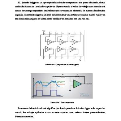
Disparador De Schmitt Trigger Histeresis 2g6067
December 2019 49
Funcionamiento Del Disparador De Schmitt Trigger 17x4m
December 2022 0More Documents from "Assini Hussain" 3x2f36

Bootstrap Sweep Circuit 6r5k3o
November 2019 73
Digital System Design Lab Manual (08.408 Btech Cse Kerala University) 2v6l6x
December 2019 29
08.607 Microcontroller Lab Manual 5y3u56
December 2019 70
08.546 Dsd With Vhdl Lecture Notes_module 1 3x2f28
November 2019 53
Schmitt Trigger 6c4m3h
February 2022 0