Tower Sizing 294p1h
This document was ed by and they confirmed that they have the permission to share it. If you are author or own the copyright of this book, please report to us by using this report form. Report 3b7i
Overview 3e4r5l
& View Tower Sizing as PDF for free.
More details w3441
- Words: 1,927
- Pages: 6
Problem Statement What is the fractional capacity in pack rating results?
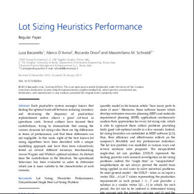
Solution There are three definitions of approach to flood that are used frequently. The first, and most common, is flooding at constant L/V. The second is flooding at constant liquid load (used often for scrubbers for which you want to process as much gas as you can with the liquid you have available). The third is flooding at constant vapor load (used very rarely for strippers where you want to process as much liquid as you can with the vapor available). The following discussion applies to the Eckert method. The Eckert method is based on the diagram given on Perry's handbook page 18-22 (see also Kister Distillation Design p 480) which gives the flooding limit for a packing. The x-axis is the flow parameter, L/G (rhog/rhol)^0.5. The y-axis is G^2 F psi mu^0.2 / rhog / rhol. The maximum fractional capacity is calculated in the following way: 1.
Calculate the value of x = L/G (rhog/rhol)^0.5 (on the example it is about 0.02)
2.
Read the value of y = G^2 F psi mu^0.2/rhog/rhol/gc from the flooding curve (on the example, it is about 0.2)
3.
This gives the gas rate at flooding Gflood = (y rhog rhol gc / F / psi / mu^0.2)^0.5
4.
Evaluate the superficial velocity of the gas VS = G/rhog (m/s or ft/s)
5.
Evaluate the capacity factor CS = VS * (rhov / (rhol - rhov))^0.5 (m/s or ft/s)
6.
Evaluate the superficial velocity of the gas at flooding VSflood = Gflood/rhog
7.
Evaluate the capacity factor at flooding CSflood = VSflood * (rhov / (rhol - rhov))^0.5 (m/s or ft/s)
This gives the fractional capacity = CS / CSflood which is reported in the pack rating results. In other words, it gives the vertical distance between the operating point and the flooding line, or for the given flow parameter (L/G) by how much you need to change the diameter of column (flooding at constant L/V).
GPDC 1 flooding line Y
flooding calc. operating point
G^2 F psi mu^0.2/rhog/rhol/gc
0.1
0.01
0.001
0.0001 0.01
X
0.1
1 L/G (rhog/rhol)^0.5
Variables rhog: gas density (lb/ft3) rhol: liquid density (lb/ft3) mu: liquid viscosity () psi: density ratio (density of water / density of liquid) Fp: packing factor (1/ft) L: liquid rate (lb/s ft2) G: gas rate (lb/s ft2) gc: conversion factor (32.2)
Problem Statement How is the capacity factor used in packing sizing/rating calculations?
Solution When doing a sizing calculation for packing, you supply the flooding approach and Aspen Plus calculates the diameter. The flooding approach is defined as:
10
% flooding =
capacity factor at design conditions -----------------------------------capacity factor at flooding
x 100
The first step is to calculate the capacity factor at flooding conditions. The packing design and rating algorithm uses correlations from vendors and/or literature to calculate this value. You can provide your own value in the optional "Capacity factor at flooding" field on the Pack Sizing/Design form. In this case, the vendor/literature correlations are not used. Next, Aspen Plus makes a guess on the tower diameter, calculates the capacity factor at this condition, and checks if the flooding approach has been met. The value for the flooding approach defaults from the packing type that was specified by the but can also be overwritten with the "Fractional approach to maximum capacity" field. If the calculated approach is not met, the procedure is repeated. As an alternative to the flooding approach, you can provide the design capacity factor. If provided, the column diameter is calculated directly and the flooding approach is not needed since it has been implicitly defined by the supplied design capacity factor.
Aspen Plus provides several methods for maximum capacity calculations. For random packings you can use: Method Mass Transfer, Ltd. (MTL ) Norton Koch Raschig Eckert
For this type of packings MTL Norton IMTP Koch Raschig All other random packings
For structured packings, Aspen Plus provides vendor procedures for each type. If you specify the maximum capacity factor, Aspen Plus byes the maximum capacity calculations. The definition of approach to maximum capacity depends on the type of packings. For Norton IMTP and Intalox structured packings, approach to maximum capacity refers to the fractional approach to the maximum efficient capacity. Efficient capacity is the operating point at which efficiency of the packing deteriorates due to liquid entrainment. The efficient capacity is approximately 10 to 20% below the flood point. For Sulzer structured packings (BX, CY, Kerapak, and Mellapak), approach to maximum capacity refers to the fractional approach to maximum capacity. Maximum capacity is the operating point at which a pressure drop of 12 mbar/m (1.47 in-water/ft) of packing is obtained. At this condition, stable operation is possible, but the gas load is higher than that at which maximum separation efficiency is achieved. The gas load corresponding to the maximum capacity is 5 to 10% below the flood point. Sulzer recommends a usual design range between 0.5 and 0.8 for approach to flooding. For Raschig random and structured packings, approach to maximum capacity refers to the fractional approach to maximum capacity. Maximum capacity is at the loading point.
For all other packings, the flood point is considered to be the maximum capacity, and approach to maximum capacity refers to the fractional approach to the flood point. Because there are different definitions for approach to maximum capacity, sizing results are not on the same basis for packings from different vendors, even when you use the same value for approach to maximum capacity. Direct performance comparison of packings from different vendors is not recommended. The capacity factor is: Cs = VS * sqrt ( Rhog/(RhoL-RhoG) Where: Cs Vs Rhog Rhol
= = = =
Capacity factor Superficial velocity of vapor to packing Density of vapor to packing Density of liquid from packing
Statement In the tray sizing utility, tray flooding results table, what does the term "flood capacity" refer to?
Solution The flood capacity is an empirical value calculated by a formula that includes tray spacing, vapor density and foaming factor. It is used to calculate the percent flooding according to the formula below: %FLOOD = (VLOAD + GPM * FPL/13000)/(AA*CAF) VLOAD = vapour loading (ACFM) GPM = liquid phase flow rate (GPM) FPL= flow path length (in) AA = active area (ft2) CAF = flood capacity factor (figure attached).
Packing Correlation Robbins correlation, found in Chemical Engineering Progress Journal - May 1991, is only valid at liquid loading factors up to 20,000 and the program flags "L is out of range" warning message once the loading factor exceeds 20,000. Note: there is a bug in 's Guide HYSYS manual- page 8-78 as it states that the correlation is valid only at "liquid loading < 20,000 Ib/hr ft2" (as opposed to liquid loading FACTOR). This is a mistake in the manual only, not in the code, and has already been logged in our Defect Control System to be corrected in the future. SLE (Sherwood - Leva - Eckert) correlation is not valid when the pressure drop per length is either < 0.05kPa/m or > 1.5kPa/m and the program flags "Pressure drop is out of range" warning message when the pressure drop exceeds the limit. This equation can be found in any Column sizing or design book. Robbins is the default correlation because it tends to predict pressure drop and hold up better, especially for newer packings. However, as mentioned it is constrained to conditions where a liquid loading factor is calculated as less than < 20,000. Outside this range use SLE so long as you are within SLE's range of validity.
What is "Weep Velocity"? On a tray if the gas rate is too low, much of the liquid may rain down through the openings of the tray (weeping), thus failing to obtain the benefit of complete flow over the tray. The gas velocity at which the "weeping" starts to occur is defined as weep velocity.
Problem Statement: What is the Vapour Load in the Flooding section of the Tray Sizing utility?
Solution: On the Tray Sizing utility, Performance Tab, Trayed Page, click on the Flooding radio button, the column that says vapour load represents the following: vap load = (vaprate) * sqrt( vapden / (liqden - vapden) ) Where the vaprate is the vapour rate shown on the Tables page of the Tray sizing utility, and liqden and vapden are the corresponding tray liquid and vapour densities, as shown on the Tables page of the tray sizing utility. A good reference for this equation is Henry Kister's Distillation Design, 1992, equation 6.1
Problem Statement How are various in the Tray Sizing Utility Calculated?
Solution Active Area: Active Area = Cross Sectional Area - Area taken by the downcomers. You can see that the Active Area is a factor of Column Diameter, Weir Length, Number of Flow Paths and downcomer type. The tray type, tray spacing, hole (or valve) count have nothing to do with it.
Estimated Number of Valves (for Valve Trays): Number of Valves = AA (active area) (ft2) * F, where F = 12 (Note: F is approximately 4.5 for Bubble Cap trays.) This is a very simple formula and does not for mechanical details such as girders or manways.
Estimated Number of Holes (for Sieve Trays): Number of Holes = Hole Area/((Pi*Dh^2)/4); Where, Hole Area = 0.907*(Dh/Ph)^2 * AA Dh = Hole Diameter Ph = Hole Pitch AA = Active Area
It appears that the hole diameter does come into this equation, but if you look closely, you can see that there is a Dh^2 term in the top and bottom of this equation, so they cancel each other out. Therefore, Dh is not really a factor in the equation, but Hole Pitch is an important term.
Problem Statement What are the correlations used to calculate flooding in the Tray Sizing Utility?
Solution For Packed columns, the flooding equations used are either Robbins or SLE, and come from the following references:
• •
"Improve Pressure Drop Prediction with a New Correlation", Lanny A. Robbins, Chem. Eng. Progress, May 1991, pp. 87-91. SLE, as summarized in "Equilibrium Staged Separations", Philip C. Wankat, Elsevier, New York, NY, 1988, pp. 420 - 425.
For Trayed columns, the flooding equations depend on the type of tray selected: bubble cap, valve or sieve tray, and come from the following references:
• • •
Bubble tray methods come from "Design of Equilibrium Stage Processes" by Bufford D. Smith, published by Wiley & Sons. Sieve tray methods are from "Mass Transfer Operations" by Robert Treybal. Valve tray methods are from the Glitsch, Koch and Nutter tray design manuals.
Refer to Section 14.16 in the Aspen HYSYS 2004 Operations Guide for more information.
Problem Statement: What does the % liquid draw mean on the Design Setup page of the Tray Sizing utility?
Solution: The % liquid draw means that if you specify 0%, HYSYS assumes that 0% of the liquid that you are drawing off the tray is sitting on the tray. If you have 200 barrels/day on the tray and you are drawing off 50 barrels per day, HYSYS will calculate flooding with 200 barrels/day. If you enter 100% HYSYS adds a volume of liquid equal to the liquid draw rate to the tray and then will calculate flooding (250 barrels/day). So at 100%, flooding increases. You can only enter this percentage in one place, so if you have more than one draw HYSYS will use that same percentage to calculate the liquid on all your draw stages.
Related Documents 3m3m1z

Tower Sizing 294p1h
April 2020 10
Cooling Tower Selection And Sizing 674w67
November 2019 53
Ms Tower 1f4v1r
September 2021 0
Marshmallow Tower 6n565s
March 2021 0
Eiffel Tower 23q13
December 2019 59