Troubleshooting Olivetti D-color Mf220_mf280_mf360 17s2c
This document was ed by and they confirmed that they have the permission to share it. If you are author or own the copyright of this book, please report to us by using this report form. Report 3b7i
Overview 3e4r5l
& View Troubleshooting Olivetti D-color Mf220_mf280_mf360 as PDF for free.
More details w3441
- Words: 52,446
- Pages: 216
Field Service Ver. 1.0 Jul. 2009
17. JAM DISPLAY
TROUBLESHOOTING 17. JAM DISPLAY • When the paper jam occurred, the message, the position jam occurred (number blinks), position of the remaining paper (number lights up), and the JAM code are displayed. NOTE • JAM code is displayed on the jam warning screen only when the following setting is set to “Display.” [Service Mode] o [System 2] o [JAM Code Display Setting]
Editado por: Hugo Luis Escalante
A0EDF4E510DA
17.1 List of JAM code
10-01
JAM type
Detection timing
Misfeed processing location
Manual by • The leading edge of the paper does not Right door feed section unblocked the sensor in front of tim. roller (PS1) even after the lapse of a given period of time after the manual by starts to feed paper.
10-02
• For paper fed from the manual by, loop forming has not been complete before a sheet enters the timing roller because the rise timing of load to perform registration is earlier than the rise timing of load to form a loop.
10-40
• For paper fed from the manual by, the image write start signal permit continues to be disabled for a predetermined period of time after the timing of the image write start signal output.
10-44
• At the start of paper feed retry, the sensor in front of tim. roller (PS1) has already detected paper age.
Y111230-2
Service Manual
Ref. page P.542
TROUBLESHOOTING
JAM code
525
17. JAM DISPLAY JAM code
11-01
JAM type
Detection timing
Tray 1 feed section
P.543
• The leading edge of the paper does not Right door unblocked the sensor in front of tim. roller Tray 1 (PS1) even after the lapse of a given period of time after the tray1 starts to feed paper. • For paper fed from the tray1, due to a delay in paper arrival, loop forming in front of the timing roller is not complete before the rise timing of the registration motor.
11-40
• For paper fed from the tray1, the image write start signal permit continues to be disabled for a predetermined period of time after the timing of the image write start signal output.
11-44
• At the start of paper feed retry, the sensor in front of tim. roller (PS1) has already detected paper age.
• Paper feed tray 1 paper feed sensor (PS23) is turned ON when the main power switch is turned ON, a door or cover is opened and closed, or a misfeed or malfunction is reset. (d-Color MF360/MF280 only)
12-40
526
Ref. page P.542
11-02
12-01
Misfeed processing location
Manual by • In case paper position is detected as Right door feed section locating properly after main power switch is turned ON, door and cover are opened / closed or jam/trouble reset is done, it is regarded as paper jam at manual by feed section.
Editado por: Hugo Luis Escalante
TROUBLESHOOTING
Field Service Ver. 1.0 Jul. 2009
• In case paper position is detected as locating properly after main power switch is turned ON, door and cover are opened / closed or jam/trouble reset is done, it is regarded as paper jam at tray 1 feed section. Tray 2 feed section
• The leading edge of the paper does not turn ON the paper feed tray 2 vertical transport sensor (PS19) even after the lapse of a given period of time after the tray 2 starts to feed paper.
Right door Tray 2
P.543
• For paper fed from the tray 2, the image write start signal permit continues to be disabled for a predetermined period of time after the timing of the image write start signal output. • Paper feed tray 2 vertical transport sensor (PS19) is turned ON when the main power switch is turned ON, a door or cover is opened and closed, or a misfeed or malfunction is reset.
Service Manual
Y111230-2
Field Service Ver. 1.0 Jul. 2009 JAM code
JAM type Tray 2 feed section
13-01
Detection timing
Misfeed processing location
• Paper feed tray 2 paper feed sensor Right door (PS20) is turned ON when the main power Tray 2 switch is turned ON, a door or cover is opened and closed, or a misfeed or malfunction is reset. (d-Color MF360/MF280 only)
Ref. page P.543
• In case paper position is detected as locating properly after main power switch is turned ON, door and cover are opened / closed or jam/trouble reset is done, it is regarded as paper jam at tray 2 feed section. Tray 3 feed section
13-40
17. JAM DISPLAY
• The leading edge of the paper does not block the tray3 vertical transport sensor (PS117) even after the set period of time has elapsed after the tray3 paper feed motor (M122) is energized.
Right door Tray 3
P.544
• The tray3 paper feed sensor (PS116) is blocked when the main power switch is set to ON, a door or cover is opened and closed, or a misfeed or malfunction is reset. Tray3 feed sec- • For paper fed from the tray3, image write start signal permit continues to be distion image write start sigabled for a predetermined period of time nal permit after the timing of image write start signal waiting jam output.
Editado por: Hugo Luis Escalante Tray 4 feed section
14-40
• The leading edge of the paper does not block the tray4 vertical transport sensor (PS126) even after the set period of time has elapsed after the tray4 paper feed motor (M123) is energized.
Right door Tray 4
P.544
• The tray4 paper feed sensor (PS125) is blocked when the main power switch is set to ON, a door or cover is opened and closed, or a misfeed or malfunction is reset.
TROUBLESHOOTING
14-01
Tray4 feed sec- • For paper fed from the tray4, image write tion image start signal permit continues to be diswrite start sigabled for a predetermined period of time nal permit after the timing of image write start signal waiting jam output.
Y111230-2
Service Manual
527
17. JAM DISPLAY JAM code 15-01
Field Service Ver. 1.0 Jul. 2009
JAM type
Detection timing
LCT feed section
• The leading edge of the paper does not block the paper feed sensor (PS1) or the vertical transport sensor (PS2) even after the set period of time has elapsed after the paper feed motor (M1) is energized.
P.545
• The paper feed sensor (PS1) is not Right door unblocked even after the lapse of a given period of time after PS1 has been blocked by a paper.
P.545
• The paper feed sensor (PS1) is blocked when the main power switch is set to ON, a door or cover is opened and closed, or a misfeed or malfunction is reset.
15-40
• For paper fed from the LCT, image write start signal permit continues to be disabled for a predetermined period of time after the timing of image write start signal output.
15-43
• There is no response to the paper feed command sent to the LCT even after the set period of time has elapsed. LCT vertical transport section
Ref. page
Right door
17-08
Misfeed processing location
• The vertical transport sensor (PS2) is blocked when the main power switch is set to ON, a door or cover is opened and closed, or a misfeed or malfunction is reset.
TROUBLESHOOTING
Editado por: Hugo Luis Escalante 17-21
• The vertical transport sensor (PS2) is not blocked even after the lapse of a given period of time after the paper feed sensor (PS1) has been blocked by a paper.
17-22
• The vertical transport sensor (PS2) is not unblocked even after the lapse of a given period of time after PS2 has been blocked by a paper.
20-01
Vertical transport section
• The sensor in front of tim. roller (PS1) is not unblocked even after the lapse of a given period of time after the paper has turned ON the paper feed tray 2 vertical transport sensor (PS19).
20-02
• For paper fed from the tray 2, loop forming has not been complete before a sheet enters the timing roller because the rise timing of load to perform registration is earlier than the rise timing of load to form a loop.
• Rise timing of load for registration is earlier than the one for making the loop at front of the timing roller at tray 3 paper feed.
528
Service Manual
Right door
P.545
P.544
Y111230-2
Field Service Ver. 1.0 Jul. 2009 JAM code
JAM type Vertical transport section
17. JAM DISPLAY
Detection timing • Rise timing of load for registration is earlier than the one for making the loop at front of the timing roller at tray 4 paper feed.
Misfeed processing location Right door
Ref. page P.544
• Rise timing of load for registration is earlier than the one for making the loop at front of the timing roller at LCT paper feed.
P.545
20-11
• The paper feed tray 2 vertical transport sensor (PS19) is not unblocked even after the lapse of a given period of time after the paper has been blocked the PS19.
P.545
20-12
• The tray3 vertical transport sensor (PS117) is not unblocked even after the lapse of a given period of time after PS117 has been blocked by a paper.
P.544
20-13
• The tray4 vertical transport sensor (PS126) is not unblocked even after the lapse of a given period of time after PS126 has been blocked by a paper.
P.544
20-21
• The paper feed tray 2 vertical transport sensor (PS19) is not blocked even after the lapse of a given period of time after the tray3 vertical transport sensor (PS117) has been blocked by a paper.
P.544
20-22
The tray3 vertical transport sensor Editado• por: Luis (PS117) is Hugo not blocked even after the Escalante
P.544
lapse of a given period of time after the tray4 vertical transport sensor (PS126) has been blocked by a paper. 2nd image transfer section
• A sheet of paper does not block the sensor in front of tim. roller (PS1) after a predetermined period of time has elapsed since the sheet unblocks PS1.
30-03
• The leading edge of paper does not unblock the paper exit sensor (PS3) since the paper feeding is started.
• The sensor in front of tim. roller (PS1) is unblocked when the main power switch is turned ON, a door or cover is opened and closed, or a misfeed or malfunction is reset.
• The paper exit sensor (PS3) is turned ON when the main power switch is turned ON, a door or cover is opened and closed, or a misfeed or malfunction is reset.
• In case paper position is detected as locating properly after main power switch is turned ON, door and cover are opened / closed or jam/trouble reset is done, it is regarded as paper jam at 2nd image transfer section.
Y111230-2
Service Manual
P.546
TROUBLESHOOTING
30-01
529
17. JAM DISPLAY JAM code 32-05
JAM type Exit section
Detection timing
• The paper exit sensor (PS3) is blocked before the lapse of a given period of time after the paper has unblocked the PS3.
• The paper exit sensor (PS3) is unblocked when the main power switch is turned ON, a door or cover is opened and closed, or a misfeed or malfunction is reset.
• In case paper position is detected as locating properly after main power switch is turned ON, door and cover are opened / closed or jam/trouble reset is done, it is regarded as paper jam at exit section. ADF turnover section
• The reverse registration sensor (PS8) is not turned OFF after a lapse of a given time after the reverse registration motion is performed.
66-21
• The reverse registration sensor (PS8) is not turned ON after a lapse of a given time after the before read sensor (PS9) is turned OFF.
ADF paper feed section
• The after separate sensor (PS4) is not turned ON after a lapse of a given time after the take-up motor (M2) is turned ON.
P.547
• The size of the original on the tray detected by ADF does not match the size of the original detected by the main body. ADF transport section
• The after separate sensor (PS4) is not turn OFF after a lapse of a given time after PS4 is turned ON.
66-13
• The registration sensor (PS3) is not turned ON after a lapse of a given time after the after separate sensor (PS4) is turned ON.
66-23
• The registration sensor (PS3) is not turned OFF after a lapse of given time after the after separate sensor (PS4) is turned OFF.
66-33
• The before read sensor (PS9) is not turned OFF after a lapse of a given time after the registration sensor (PS3) is turned OFF.
530
P.547
Editado por: Hugo Luis Escalante
66-12
66-03
Ref. page P.546
Left cover • The before read sensor (PS9) is not turned ON after a lapse of a given time after the reverse registration motion is performed.
66-11
66-02
Misfeed processing location
• The paper exit sensor (PS3) is not blocked Right door even after the lapse of a given period of time after the paper has unblocked PS3.
32-31
66-01
TROUBLESHOOTING
Field Service Ver. 1.0 Jul. 2009
Service Manual
P.548
Y111230-2
Field Service Ver. 1.0 Jul. 2009 JAM code 66-04
JAM type
17. JAM DISPLAY
Detection timing
ADF paper exit • The exit sensor (PS5) is not turned ON section after a lapse of a given time after the before read sensor (PS9) is turned ON.
66-14
• The exit sensor (PS5) is not turned OFF after a lapse of a given time after the before read sensor (PS9) is turned OFF.
66-24
• The exit sensor (PS5) is not turned ON after a lapse of a given time after the before read sensor (PS9) is turned OFF.
66-34
• The exit sensor (PS5) is not turned OFF after a lapse of a given time after the turnover and paper exit motion is performed.
66-05
ADF image reading section
Left cover
• The before read sensor (PS9) is not turned OFF after a lapse of a given time after the reverse registration sensor (PS8) is turned OFF.
66-06
• The before read sensor (PS9) is turned ON earlier than a given time after the before read sensor (PS9) is turned OFF during original transportation.
Ref. page P.548
P.549
• The before read sensor (PS9) is not turned ON after a lapse of a given time after the registration sensor (PS3) is turned ON.
66-15
66-07
Misfeed processing location
Due to a remaining sheet of paper that Editado• por: Hugo Luis Escalante has not been detected by sensors, before
72-14
FS transport section
<When FS-527 is installed> Front door • The saddle path sensor (PS11) is not turned ON even after the set period of time has elapsed after the lower path sensor (PS9) is turned ON by the paper.
P.549
72-15
<When FS-527 is installed> • The saddle path sensor (PS11) is not turn OFF even after the set period of time has elapsed after it turns ON.
P.550
72-16
<When FS-527 is installed> • The paper age sensor/1 (PS1) is not turned ON even after the set period of time has elapsed after the copier's exit sensor (PS3) is turned ON by the paper. • The paper age sensor/1 (PS1) is not turned OFF even after the set period of time has elapsed after it is turned ON by the paper.
Y111230-2
Service Manual
Horizontal conveyance cover
P.550
531
TROUBLESHOOTING
the start of a job, a sensor detects the sheet at an unexpected timing.
17. JAM DISPLAY JAM code
JAM type Job separator transport section
Field Service Ver. 1.0 Jul. 2009
Detection timing
Misfeed processing location
Ref. page
Misfeed clearing <When JS-505 is installed> cover • The lower tray exit sensor (PS1) is not turned ON even after the set period of time has elapsed after the copier’s paper exit sensor (PS3) is turned ON by the paper. • The upper tray exit sensor (PS2) is not turned ON even after the set period of time has elapsed after the copier’s paper exit sensor (PS3) is turned ON by the paper. • The lower tray exit sensor (PS1) is not turned OFF even after the set period of time has elapsed after the copier’s paper exit sensor (PS3) is turned OFF by the paper. • The upper tray exit sensor (PS2) is not turned OFF even after the set period of time has elapsed after the copier’s paper exit sensor (PS3) is turned OFF by the paper. • The paper exit sensor (PS25) is not turned OFF even after the set period of time has elapsed after the copier’s paper exit sensor (PS3) is turned ON by the paper. • The lower tray exit sensor (PS1) is turned ON when the power switch is set to ON, a door or cover is opened and closed, or a misfeed or malfunction is reset. • The upper tray exit sensor (PS2) is turned ON when the power switch is set to ON, a door or cover is opened and closed, or a misfeed or malfunction is reset.
P.550
Horizontal convey<When FS-527 is installed> • The paper age sensor/2 (PS2) is not ance cover turned ON even after the set period of time has elapsed after the paper age sensor/1 (PS1) is turned ON by the paper. • The paper age sensor/2 (PS2) is not turn OFF even after the set period of time has elapsed after it turns ON. Front door <When FS-529 is installed> • The paper age sensor/2 (PS10) is not turned ON even after the set period of time has elapsed after the paper age sensor/1 (PS1) is turned ON by the paper. • The paper age sensor/2 (PS10) is not turned OFF even after the set period of time has elapsed after the paper age sensor/2 (PS10) is turned ON by the paper.
P.551
Editado por: Hugo Luis Escalante
TROUBLESHOOTING
72-17
532
FS transport section
Service Manual
Y111230-2
Field Service Ver. 1.0 Jul. 2009 JAM code 72-18
JAM type FS transport section
72-19
17. JAM DISPLAY
Detection timing
Misfeed processing location
Ref. page
Horizontal convey<When FS-527 is installed> ance cover • The registration sensor (PS10) is not turned ON even after the set period of time has elapsed after the paper age sensor/2 (PS2) is turned ON by the paper. • The registration sensor (PS10) is not turn OFF even after the set period of time has elapsed after it turns ON.
P.552
Front door <When FS-527 is installed> • The lower path sensor (PS9) is not turned ON even after the set period of time has elapsed after the registration sensor (PS10) is turned ON by the paper. • The lower path sensor (PS9) is not turn OFF even after the set period of time has elapsed after it turns ON. • The upper path sensor (PS8) is not turned ON even after the set period of time has elapsed after the registration sensor (PS10) is turned ON by the paper. • The upper path sensor (PS8) is not turn OFF even after the set period of time has elapsed after it turns ON. • The lower path sensor (PS9) is not turned ON by the paper even after the set period of time has elapsed after the switchback operation caused by the conveyance motor (M4) is completed. • After the switchback operation caused by the conveyance motor (M4) is completed, the lower path sensor (PS9) is not turned OFF even after the set period of time has elapsed after PS9 is turn ON by the paper.
P.552
Front door <When FS-527 is installed> • The tray2 paper detection sensor (PS16) is not turned ON even after the set period of time has elapsed after the lower path sensor (PS9) is turned ON by the paper. <When FS-529 is installed> • The paper empty sensor (PS7) is not turned ON even after the set period of time has elapsed after the paper age sensor/2 (PS10) is turned ON by the paper. • The paper empty sensor (PS7) is not turned OFF even after the set period of time has elapsed after the paper empty sensor (PS7) is turned ON by the paper.
P.552
72-21
Y111230-2
Service Manual
TROUBLESHOOTING
Editado por: Hugo Luis Escalante
533
17. JAM DISPLAY JAM code
JAM type
Field Service Ver. 1.0 Jul. 2009
Detection timing
Misfeed processing location
Ref. page
72-22
FS transport section
Front door <When FS-527 is installed> • The tray1 path sensor (PS6) is not turned ON even after the set period of time has elapsed after the registration sensor (PS10) is turned ON by the paper. • The tray1 path sensor (PS6) is not turn OFF even after the set period of time has elapsed after it turns ON.
P.553
72-26
SD paper exit section
<When FS-527+SD-509 is installed> • The paper detection sensor/2 (PS44) is not turn OFF even after the set period of time has elapsed after it turns ON.
Front door, stacker unit
P.553
72-43
PK JAM
<When FS-527+PK-517 is installed> • Though the punch home sensor/1 (PS100) is not turned ON after the punch motor/1 (M100) starts rotating forward, PS100 is turned ON after M100 starts rotating backward.
Front door
P.554
72-81
FS staple section
• Though the stapler sensor is not turned Front door, Front ON after the stapler motor starts rotating cover forward, the stapler sensor is turned ON after the stapler motor starts rotating backward.
P.554
72-85
SD staple section
Front door, stacker <When FS-527+SD-509 is installed> • Though the saddle stapler home sensor is unit not turned ON after the saddle stapler motor starts rotating forward, the saddle stapler home sensor is turned ON after the saddle stapler motor starts rotating backward.
P.554
SD transport section
<When FS-527+SD-509 is installed> • The paper detection sensor/1 (PS43) is not turned ON even after the set period of time has elapsed after the saddle path sensor (PS11) is turned ON by the paper.
P.555
<When FS-527+SD-509 is installed> • The paper detection sensor/2 (PS44) is not turned ON even after the set period of time has elapsed after the saddle path sensor (PS11) is turned ON by the paper.
P.555
Editado por: Hugo Luis Escalante
TROUBLESHOOTING
72-86
72-87
534
Service Manual
Y111230-2
Field Service Ver. 1.0 Jul. 2009 JAM code
Duplex pre-registration section
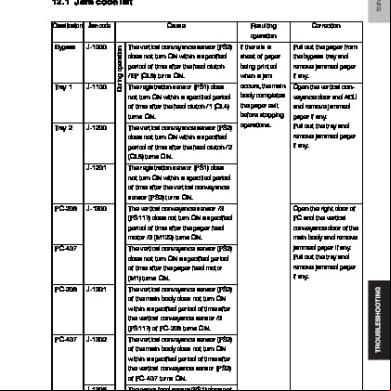
Detection timing • The sensor in front of tim. roller (PS1) is not unblocked even after the lapse of a given period of time after a duplex paper feed sequence has been started.
92-02
• For the second-side feed of paper in the duplex mode, loop forming has not been complete before the second side of a sheet enters the timing roller because the rise timing of load to perform registration is earlier than the rise timing of load to form a loop.
92-40
• For the second-side feed of paper in the duplex mode, the image write start signal permit continues to be disabled for a predetermined period of time after the timing of the image write start signal output.
93-01
Duplex transport section
93-10
99-01
Misfeed processing location Right door
• The duplex paper age sensor (PS40) Duplex door is not blocked even after lapse of a given period of time after starting of switch back.
Ref. page P.556
P.556
• The paper does not unblock the duplex paper age sensor (PS40) even after lapse of a given period of time after the paper has blocked the PS40. • In case the duplex paper age sensor (PS40) is blocked after main power switch is turned ON, door and cover are opened / closed or jam/trouble reset is done, it is regarded as paper jam at duplex transport section.
Editado por: Hugo Luis Escalante Controller JAM • Forced stop command was sent from the controller to the printer engine due to the error in paper size, media, etc. • Media error has occurred in both sides printing.
17.1.1
TROUBLESHOOTING
92-01
JAM type
17. JAM DISPLAY
Misfeed display resetting procedure
• Open the corresponding door, clear the sheet of paper misfed, and close the door.
Y111230-2
Service Manual
535
17. JAM DISPLAY
Field Service Ver. 1.0 Jul. 2009
17.2 Sensor layout 17.2.1
Main body
[1]
[2]
[3]
Editado por: Hugo Luis Escalante [4]
[5]
TROUBLESHOOTING
[6]
A0EDF4C501DA
[1] Paper exit sensor (PS3)
[4] Paper feed tray 1 paper feed sensor (PS23) *1
[2] Duplex paper age sensor (PS40)
[5] Paper feed tray 2 vertical transport sensor (PS19)
[3] Sensor in front of tim. roller (PS1)
[6] Paper feed tray 2 paper feed sensor (PS20) *1
*1: d-Color MF360/MF280 only
536
Service Manual
Y111230-2
Field Service Ver. 1.0 Jul. 2009 17.2.2
17. JAM DISPLAY
DF-617
[4]
[3]
[5]
[1]
[2]
A0HUF4C500DA
[1]
Exit sensor (PS5)
[4]
Registration sensor (PS3)
[2]
Reverse registration sensor (PS8)
[5]
After separate sensor (PS4)
[3]
Before read sensor (PS9)
TROUBLESHOOTING
Editado por: Hugo Luis Escalante
Y111230-2
Service Manual
537
17. JAM DISPLAY 17.2.3
Field Service Ver. 1.0 Jul. 2009
PC-107/PC-207
[1]
Editado por: Hugo Luis Escalante [2] [3] [4]
TROUBLESHOOTING
[5] [6]
A0XWF4C500DA
[1]
Sensor in front of tim. roller (PS1)
[4]
Tray3 paper feed sensor (PS116)
[2]
Paper feed tray 2 vertical transport sensor (PS19)
[5]
Tray4 vertical transport sensor (PS126)
[3]
Tray3 vertical transport sensor (PS117)
[6]
Tray4 paper feed sensor (PS125)
538
Service Manual
Y111230-2
Field Service Ver. 1.0 Jul. 2009 17.2.4
17. JAM DISPLAY
PC-408
[1]
Editado por: Hugo Luis Escalante [2] [3]
TROUBLESHOOTING
[4]
A0XWF4C501DA
[1]
Sensor in front of tim. roller (PS1)
[3]
Vertical transport sensor (PS2)
[2]
Paper feed tray 2 vertical transport sensor (PS19)
[4]
Paper feed sensor (PS1)
Y111230-2
Service Manual
539
17. JAM DISPLAY 17.2.5
Field Service Ver. 1.0 Jul. 2009
JS-505
[3]
[1]
[2] A083F4C501DA
[1]
Paper exit sensor (PS3)
[2]
Lower tray exit sensor (PS1)
17.2.6
[3]
Upper tray exit sensor (PS2)
FS-529 [2] Editado por: Hugo Luis Escalante [3]
TROUBLESHOOTING
[1]
A0U7F4C500DA
[1]
Paper age sensor/1 (PS1)
[2]
Paper age sensor/2 (PS10)
540
[3]
Service Manual
Paper empty sensor (PS7)
Y111230-2
Field Service Ver. 1.0 Jul. 2009 17.2.7
17. JAM DISPLAY
FS-527/SD-509/PK-517/JS-603
[4] [3]
[1]
[2]
[10]
[9] [5]
[8] [6]
Editado por: Hugo Luis Escalante
A0HRF4C500DA
[1]
Paper age sensor/1 (PS1)
[6]
Paper detection sensor/1 (PS43)
[2]
Paper age sensor/2 (PS2)
[7]
Paper detection sensor/2 (PS44)
[3]
Registration sensor (PS10)
[8]
Lower path sensor (PS9)
[4]
Tray1 path sensor (PS6)
[9]
Tray2 paper detection sensor (PS16)
[5]
Saddle path sensor (PS11)
[10] Upper path sensor (PS8)
Y111230-2
Service Manual
541
TROUBLESHOOTING
[7]
17. JAM DISPLAY
Field Service Ver. 1.0 Jul. 2009
17.3 Solution 17.3.1
Initial check items
• When a paper misfeed occurs, first perform the following initial check items. Check item
Action
Does paper meet product specifications?
Replace paper.
Is the paper curled, wavy, or damp?
Replace paper.
Is a foreign object present along the paper path, or is the paper path deformed or worn?
Clean the paper path and replace if necessary.
Are rolls/rollers dirty, deformed, or worn?
Clean or replace the defective roll/roller.
Are the edge guide and trailing edge stop at the cor- Set as necessary. rect position to accommodate the paper? Are the actuators operating correctly?
17.3.2
Correct or replace the defective actuator.
Misfeed at manual by feed section Relevant parts
Transport motor (M1) Manual paper feed clutch (CL7) Manual pick-up solenoid (SD1)
Front side relay board (FREYB) Printer control board (PRCB) Sensor in front of tim. roller (PS1) WIRING DIAGRAM
TROUBLESHOOTING
Step
542
Action
Control signal
Location (Electrical component)
Editado por: Hugo Luis— Escalante—
1
Initial check items
2
PS1 I/O check, sensor check
FREYB CN13-3 (ON)
Q-17
3
CL7 operation check
PRCB CN15-2 (ON)
C-6
4
SD1 operation check
PRCB CN19-17 (ON)
C-10
5
M1 operation check
PRCB CN14-2 (REM) PRCB CN14-5 (LOCK)
C-2 to 5
6
PRCB I5 conduction check
—
—
7
Change FREYB
—
—
8
Change PRCB
—
—
Service Manual
Y111230-2
Field Service Ver. 1.0 Jul. 2009 17.3.3
17. JAM DISPLAY
Misfeed at tray 1 feed section Relevant parts
Transport motor (M1) Paper feed tray 1 paper feed clutch (CL3) Paper feed tray 1 paper feed sensor (PS23)
Front side relay board (FREYB) Printer control board (PRCB) Sensor in front of tim. roller (PS1) WIRING DIAGRAM
Step
Action
Control signal
Location (Electrical component)
—
—
1
Initial check items
2
PS1 I/O check, sensor check
FREYB CN13-3 (ON)
Q-17
3
PS23 I/O check, sensor check (d-Color MF360/MF280 only)
PRCB CN21-10 (ON)
C-21
4
CL3 operation check
PRCB CN21-8 (ON)
C-21
5
M1 operation check
PRCB CN14-2 (REM) PRCB CN14-5 (LOCK)
C-2 to 5
6
PRCB I5, 15 conduction check
—
—
7
Change FREYB
—
—
8
Change PRCB
—
—
17.3.4
Misfeed at tray 2 feed section Relevant parts
control board (PRCB) Editado por: HugoPrinter Luis Escalante Paper feed tray 2 vertical transport sensor (PS19)
Transport motor (M1) Paper feed tray 2 paper feed clutch (CL1) Paper feed tray 2 vertical transport clutch (CL2)
Paper feed tray 2 paper feed sensor (PS20) WIRING DIAGRAM
Action
Control signal
Location (Electrical component)
—
—
1
Initial check items
2
PS19 I/O check, sensor check
PRCB CN22-15 (ON)
C-25
3
PS20 I/O check, sensor check (d-Color MF360/MF280 only)
PRCB CN22-12 (ON)
C-25
4
CL1 operation check
PRCB CN22-10 (ON)
C-25
5
CL2 operation check
PRCB CN22-18 (ON)
C-24
M1 operation check
PRCB CN14-2 (REM) PRCB CN14-5 (LOCK)
C-2 to 5
6 7
PRCB I5, 15 conduction check
—
—
8
Change PRCB
—
—
Y111230-2
Service Manual
TROUBLESHOOTING
Step
543
17. JAM DISPLAY 17.3.5
Field Service Ver. 1.0 Jul. 2009
Tray3 feed section/vertical transport section misfeed Relevant parts
Tray3 paper feed sensor (PS116) PC Control board (PCCB) Tray3 vertical transport sensor (PS117) Paper feed tray 2 vertical transport sensor (PS19) Tray3 paper feed motor (M122) Tray3 vertical transport motor (M120) Sensor in front of tim. roller (PS1) WIRING DIAGRAM Step
Action
Control signal
Location (Electrical component)
—
—
FREYB CN13-3 (ON)
C360/C280/ C220 Q-17
1
Initial check items
2
PS1 I/O check, sensor check
3
PS116 I/O check, sensor check
PCCB CN6-8 (ON)
PC-207 B-2
4
PS117 I/O check, sensor check
PCCB CN6-11 (ON)
PC-207 B-2
5
PS19 I/O check, sensor check
RCB CN22-(ON)
C360/C280 C-25
6
M122 operation check
PCCB CN5-1 to 4
PC-207 B-3
7
M120 operation check
PCCB CN5-5 to 8
PC-207 B-3
8
PCCB I1, I3 conduction check
—
—
9
Change PCCB
—
—
17.3.6
Editado por: Hugo Luis Escalante
Tray4 feed section/vertical transport section misfeed Relevant parts
TROUBLESHOOTING
Tray4 paper feed sensor (PS125) Tray4 vertical transport sensor (PS126) Tray3 vertical transport sensor (PS117) Tray4 paper feed motor (M123) Tray4 vertical transport motor (M121) Sensor in front of tim. roller (PS1)
PC Control board (PCCB)
WIRING DIAGRAM Step
544
Action
Control signal
Location (Electrical component)
—
—
1
Initial check items
2
PS1 I/O check, sensor check
FREYB CN13-3 (ON)
C360/C280/ C220 Q-17
3
PS125 I/O check, sensor check
PCCB CN10-8 (ON)
PC-207 G-4 to 5
4
PS126 I/O check, sensor check
PCCB CN11-2 (ON)
PC-207 G-5
5
PS117 I/O check, sensor check
PCCB CN6-11 (ON)
PC-207 B-2
6
M123 operation check
PCCB CN9-1 to 4
PC-207 G-5 to 6
7
M121 operation check
PCCB CN9-6 to 9
PC-207 G-6
8
PCCB I1, I2 conduction check
—
—
9
Change PCCB
—
—
Service Manual
Y111230-2
Field Service Ver. 1.0 Jul. 2009 17.3.7
17. JAM DISPLAY
LCT paper feed section/vertical transport section misfeed Relevant parts
Paper feed sensor (PS1) Vertical transport sensor (PS2) Paper feed motor (M1) Vertical transport motor (M2)
PC Control board (PCCB) MFP board (MFPB)
WIRING DIAGRAM Step
Action
Control signal
Location (Electrical component)
—
—
1
Initial check items
2
PS1 I/O check, sensor check
PCCB CN5-2 (ON)
PC-408 G-9
3
PS2 I/O check, sensor check
PCCB CN5-5 (ON)
PC-408 G-9
4
M1 operation check
PCCB CN6-1 to 4
PC-408 G-10
5
M2 operation check
PCCB CN6-5 to 8
PC-408 G-9
6
PCCB I1, I2 conduction check
—
—
7
Change PCCB
—
—
8
Change MFPB
—
—
17.3.8
Misfeed at vertical transport section Relevant parts
Transport motor (M1) Paper feed tray 2 vertical transport clutch (CL2) Registration roller clutch (CL4)
Front side relay board (FREYB) Printer control board (PRCB) Sensor in front of tim. roller (PS1) Paper feed tray 2 vertical transport sensor (PS19)
Editado por: Hugo Luis Escalante WIRING DIAGRAM Action
Control signal
Location (Electrical component)
—
—
1
Initial check items
2
PS1 I/O check, sensor check
FREYB CN13-3 (ON)
Q-17
3
PS19 I/O check, sensor check
PRCB CN22-15 (ON)
C-25
4
CL2 operation check
PRCB CN22-18 (ON)
C-24
5
CL4 operation check
FREYB CN13-5 (REM)
Q-17
6
M1 operation check
PRCB CN14-2 (REM) PRCB CN14-5 (LOCK)
C-2 to 5
7
Change FREYB
—
—
8
PRCB I2 conduction check
—
—
9
PRCB I14 conduction check
—
—
10
Change PRCB
—
—
Y111230-2
Service Manual
TROUBLESHOOTING
Step
545
17. JAM DISPLAY 17.3.9
Field Service Ver. 1.0 Jul. 2009
Misfeed at 2nd image transfer section Relevant parts
Transport motor (M1) Registration roller clutch (CL4) Paper exit sensor (PS3)
Front side relay board (FREYB) Printer control board (PRCB) Sensor in front of tim. roller (PS1) WIRING DIAGRAM
Step
Action
Control signal
Location (Electrical component)
—
—
1
Initial check items
2
PS1 I/O check, sensor check
FREYB CN13-3 (ON)
Q-17
3
PS3 I/O check, sensor check
PRCB CN19-15 (ON)
C-10
4
CL4 operation check
FREYB CN13-5 (REM)
Q-17
5
M1 operation check
PRCB CN14-2 (REM) PRCB CN14-5 (LOCK)
C-2 to 5
6
Change FREYB
—
—
7
Change PRCB
—
—
17.3.10
Misfeed at exit section Relevant parts
Transport motor (M1) Fusing motor (M3) Registration roller clutch (CL4)
Front side relay board (FREYB) Printer control board (PRCB) Paper exit sensor (PS3)
Editado por: Hugo Luis Escalante WIRING DIAGRAM
TROUBLESHOOTING
Step
546
Action
Control signal
Location (Electrical component)
—
—
PRCB CN19-15 (ON)
C-10
1
Initial check items
2
PS3 I/O check, sensor check
3
CL4 operation check
FREYB CN13-5 (REM)
Q-17
4
M1 operation check
PRCB CN14-2 (REM) PRCB CN14-5 (LOCK)
C-2 to 5
5
M3 operation check
PRCB CN11-9 (REM) PRCB CN11-12 (LOCK)
J-6
6
Change FREYB
—
—
7
Change PRCB
—
—
Service Manual
Y111230-2
Field Service Ver. 1.0 Jul. 2009 17.3.11
17. JAM DISPLAY
ADF turnover section Relevant parts
Reverse roller pressure/retraction motor (M5) Before read sensor (PS9) Reverse registration sensor (PS8)
DF control board (DFCB)
WIRING DIAGRAM Step
Action
Control signal
Location (Electrical component)
—
—
1
Initial check items
2
PS9 I/O check, sensor check
DFCB PJ14-8 (ON)
DF-617 B to C-7
3
PS8 I/O check, sensor check
DFCB PJ12-2 (ON)
DF-617 I-4
4
M5 operation check
DFCB PJ6-10 to 13
DF-617 I-5
5
DFCB F10 conduction check
—
—
6
Change DFCB
—
—
17.3.12
ADF paper feed section Relevant parts
Take-up motor (M8) After separate sensor (PS4) Length sensor/1 (PS10) Length sensor/2 (PS11) Length sensor/3 (PS12)
DF control board (DFCB)
Step
Action
Control signal
Location (Electrical component)
—
—
1
Initial check items
2
PS4 I/O check, sensor check
DFCB PJ11-5 (ON)
DF-617 B to C-6
3
PS10 I/O check, sensor check
REYB PJ5-12 (ON)
DF-617 L-5 to 6
4
PS11 I/O check, sensor check
REYB PJ5-8 (ON)
DF-617 L-6
5
PS12 I/O check, sensor check
REYB PJ5-6 (ON)
DF-617 L-6
6
M8 operation check
DFCB PJ9-5 to 8
DF-617 I-10
7
DFCB F4 conduction check
—
—
8
Change DFCB
—
—
Y111230-2
Service Manual
547
TROUBLESHOOTING
Editado por: Hugo Luis Escalante WIRING DIAGRAM
17. JAM DISPLAY 17.3.13
Field Service Ver. 1.0 Jul. 2009
ADF transport section Relevant parts
Registration motor (M2) Take-up motor (M8) Registration sensor (PS3) After separate sensor (PS4) Before read sensor (PS9)
DF control board (DFCB)
WIRING DIAGRAM Step
Action
Control signal
Location (Electrical component)
—
—
1
Initial check items
2
PS3 I/O check, sensor check
DFCB PJ10-11 (ON)
DF-617 B to C-4
3
PS4 I/O check, sensor check
DFCB PJ11-5 (ON)
DF-617 B to C-6
4
PS9 I/O check, sensor check
DFCB PJ14-8 (ON)
DF-617 B to C-7
5
M2 operation check
DFCB PJ8-5 to 10
DF-617 I-9
6
M8 operation check
DFCB PJ9-5 to 8
DF-617 I-10
7
DFCB F2, F9, F10 conduction check
—
—
8
Change DFCB
—
—
17.3.14
ADF paper exit section Relevant parts
DF control board (DFCB) Editado por: Hugo Luis Escalante
Exit motor (M3) Before read sensor (PS9) Exit sensor (PS5)
WIRING DIAGRAM
TROUBLESHOOTING
Step
548
Action
Control signal
Location (Electrical component)
—
—
1
Initial check items
2
PS9 I/O check, sensor check
DFCB PJ14-8 (ON)
DF-617 B to C-7
3
PS5 I/O check, sensor check
DFCB PJ13-3 (ON)
DF-617 I-9
4
M3 operation check
DFCB PJ8-1 to 4
DF-617 I-9 to 10
5
DFCB F1, F6 conduction check
—
—
6
Change DFCB
—
—
Service Manual
Y111230-2
Field Service Ver. 1.0 Jul. 2009 17.3.15
17. JAM DISPLAY
ADF image reading section Relevant parts
Reading motor (M1) Reading roller pressure/retraction motor (M4) Registration sensor (PS3) Reverse registration sensor (PS8) Before read sensor (PS9)
DF control board (DFCB)
WIRING DIAGRAM Step
Action
Control signal
Location (Electrical component)
1
Initial check items
—
—
2
Make the adjustment of original stop position. See P.474
—
—
3
PS3 I/O check, sensor check
DFCB PJ10-11 (ON)
DF-617 B to C-4
4
PS8 I/O check, sensor check
DFCB PJ12-2 (ON)
DF-617 I-4
5
PS9 I/O check, sensor check
DFCB PJ14-8 (ON)
DF-617 B to C-7
6
M1 operation check
DFCB PJ9-1 to 4
DF-617 I-10
7
M4 operation check
DFCB PJ6-5 to 6
DF-617 I-4
8
DFCB F3, F6 conduction check
—
—
9
Change DFCB
—
—
Code: 72-14 Editado por: Hugo Luis Escalante
17.3.16
Relevant parts Lower path sensor (PS9) Saddle path sensor (PS11) Conveyance motor (M4)
FS control board (FSCB)
Step
Action
Control signal
Location (Electrical component)
—
—
1
Initial check items
2
PS9 I/O check, sensor check
FSCB PJ16-5 (ON)
FS-527 J-4
3
PS11 I/O check, sensor check
FSCB PJ13-6 (ON)
FS-527 B to C-5
4
M4 operation check
FSCB PJ10-5 to 8
FS-527 B to C-3
5
FSCB F7 conduction check
—
—
6
Change FSCB
—
—
Y111230-2
Service Manual
549
TROUBLESHOOTING
WIRING DIAGRAM
17. JAM DISPLAY 17.3.17
Field Service Ver. 1.0 Jul. 2009
Code: 72-15 Relevant parts
Saddle path sensor (PS11)
FS control board (FSCB) WIRING DIAGRAM
Step
Action
1
Initial check items
2
PS11 I/O check, sensor check
3
Change FSCB
17.3.18
Control signal
Location (Electrical component)
—
—
FSCB PJ13-6 (ON)
FS-527 B to C-5
—
—
Code: 72-16
(1) When FS-527 is installed Relevant parts Paper exit sensor (PS3) Paper age sensor/1 (PS1) Paper age motor/1 (M1) Paper age motor/2 (M3)
FS control board (FSCB)
WIRING DIAGRAM
TROUBLESHOOTING
Step
Action
Control signal
Location (Electrical component)
—
—
1
Initial check items
2
PS3 I/O check, sensor check
3
PS1 I/O check, sensor check
FSCB PJ11-2 (ON)
FS-527 I-11 to 12
4
M1 operation check
FSCB PJ28-1 to 4
FS-527 I-12
5
M3 operation check
FSCB PJ7-1 to 4
FS-527 C to B-3
6
FSCB F5, F6 conduction check
—
—
7
Change FSCB
—
—
d-Color MF360/ Editado por: Hugo PRCB Luis Escalante CN19-15 (ON) MF280/MF220 C-10
(2) When FS-529 is installed Relevant parts Paper exit sensor (PS3) Paper age sensor/1 (PS1)
FS control board (FSCB)
WIRING DIAGRAM Step
550
Action
Control signal
Location (Electrical component)
—
—
1
Initial check items
2
PS3 I/O check, sensor check
PRCB CN19-15 (ON)
3
PS1 I/O check, sensor check
FSCB CN3-3 (ON)
FS-529 B-3
4
Change FSCB
—
—
Service Manual
d-Color MF360/ MF280/MF220 C-10
Y111230-2
Field Service Ver. 1.0 Jul. 2009
17. JAM DISPLAY
(3) When JS-505 is installed Relevant parts Paper exit sensor (PS3) Lower tray exit sensor (PS1) Upper tray exit sensor (PS2) Transport motor (M1)
JS control board (JSCB) Printer control board (PRCB)
WIRING DIAGRAM Step
Action
Control signal
Location (Electrical component)
—
—
1
Initial check items
2
PS3 I/O check, sensor check
PRCB CN19-15 (ON)
3
PS1 I/O check, sensor check
JSCB PJ7-6 (ON)
JS-505 F-4 to 5
4
PS2 I/O check, sensor check
JSCB P7-9 (ON)
JS-505 F-4
5
M1 operation check
JSCB PJ5-1 to 4
JS-505 B-2 to 3
6
JSCB F7 conduction check
—
—
7
Change JSCB
—
—
8
Change PRCB
—
—
17.3.19
d-Color MF360/ MF280/MF220 C-10
Code: 72-17
(1) When FS-527 is installed
Editado por: HugoFSLuis Escalante control board (FSCB) Relevant parts
Paper age sensor/1 (PS1) Paper age sensor/2 (PS2)
Action
Control signal
Location (Electrical component)
—
—
1
Initial check items
2
PS1 I/O check, sensor check
FSCB PJ11-2 (ON)
FS-527 I-11 to 12
3
PS2 I/O check, sensor check
FSCB PJ11-8 (ON)
FS-527 I-11
4
Change FSCB
—
—
(2) When FS-529 is installed Relevant parts Paper age sensor/1 (PS1) Paper age sensor/2 (PS10)
FS control board (FSCB)
WIRING DIAGRAM Step
Action
Control signal
Location (Electrical component)
—
—
1
Initial check items
2
PS1 I/O check, sensor check
FSCB PJ11-2 (ON)
FS-527 I-11 to 12
3
PS10 I/O check, sensor check
FSCB CN7-3 (ON)
FS-529 B-4 to 5
4
Change FSCB
—
—
Y111230-2
Service Manual
551
TROUBLESHOOTING
WIRING DIAGRAM Step
17. JAM DISPLAY 17.3.20
Field Service Ver. 1.0 Jul. 2009
Code: 72-18 Relevant parts
Paper age sensor/2 (PS2) Registration sensor (PS10)
FS control board (FSCB)
WIRING DIAGRAM Step
Action
Control signal
Location (Electrical component)
—
—
1
Initial check items
2
PS2 I/O check, sensor check
FSCB PJ11-8 (ON)
FS-527 I-11
3
PS10 I/O check, sensor check
FSCB PJ13-8 (ON)
FS-527 B to C-5
4
Change FSCB
—
—
17.3.21
Code: 72-19 Relevant parts
Conveyance motor (M4) Upper path sensor (PS8) Lower path sensor (PS9) Registration sensor (PS10)
Printer control board (PRCB)
WIRING DIAGRAM
TROUBLESHOOTING
Step
Action
Control signal
Location (Electrical component)
Editado por: Hugo Luis— Escalante—
1
Initial check items
2
PS8 I/O check, sensor check
FSCB PJ14-12 (ON)
FS-527 J-5
3
PS9 I/O check, sensor check
FSCB PJ16-5 (ON)
FS-527 J-4
4
PS10 I/O check, sensor check
FSCB PJ13-8 (ON)
FS-527 B to C-5
5
M4 operation check
FSCB PJ10-5 to 8
FS-527 B to C-3
6
FSCB F7 conduction check
—
—
7
Change FSCB
—
—
17.3.22
Code: 72-21
(1) When FS-527 is installed Relevant parts Lower path sensor (PS9) Tray2 paper detection sensor (PS16)
FS control board (FSCB)
WIRING DIAGRAM Step
552
Action
Control signal
Location (Electrical component)
—
—
1
Initial check items
2
PS9 I/O check, sensor check
FSCB PJ16-5 (ON)
FS-527 J-4
3
PS16 I/O check, sensor check
FSCB PJ17-8 (ON)
FS-527 B to C-8
4
Change FSCB
—
—
Service Manual
Y111230-2
Field Service Ver. 1.0 Jul. 2009
17. JAM DISPLAY
(2) When FS-529 is installed Relevant parts Paper age sensor/2 (PS10) Paper empty sensor (PS7)
FS control board (FSCB)
WIRING DIAGRAM Step
Action
Control signal
Location (Electrical component)
—
—
1
Initial check items
2
PS10 I/O check, sensor check
FSCB CN7-3 (ON)
FS-529 B-4 to 5
3
PS7 I/O check, sensor check
FSCB CN6-3 (ON)
FS-529 B-1 to 2
4
Change FSCB
—
—
17.3.23
Code: 72-22 Relevant parts
Registration sensor (PS10) Tray1 path sensor (PS6)
FS control board (FSCB)
WIRING DIAGRAM Step
Action
1
Initial check items
2
PS10 I/O check, sensor check
3
PS6 I/O check, sensor check
4
Change FSCB
Control signal
Location (Electrical component)
—
—
Editado por: Hugo Luis Escalante FSCB PJ14-9 (ON) FS-527 J-5
17.3.24
FSCB PJ13-8 (ON)
FS-527 B to C-5
—
—
Code: 72-26 Relevant parts SD drive board (SDDB) FS control board (FSCB) WIRING DIAGRAM
Step
Action
Control signal
Location (Electrical component)
—
—
SDDB PJ13-2 (ON)
SD-509 G-3
1
Initial check items
2
PS44 I/O check, sensor check
3
Change SDDB
—
—
4
Change FSCB
—
—
Y111230-2
Service Manual
553
TROUBLESHOOTING
Paper detection sensor/2 (PS44)
17. JAM DISPLAY 17.3.25
Field Service Ver. 1.0 Jul. 2009
Code: 72-43 Relevant parts
Punch motor/1 (M100) Punch home sensor/1 (PS100)
FS control board (FSCB)
WIRING DIAGRAM Step
Action
1
Initial check items
2
PS100 I/O check, sensor check
3
M100 operation check
4
Change FSCB
17.3.26
Control signal
Location (Electrical component)
—
—
FSCB PJ19-8 (ON)
FS-527 (PK-517) J-9
FSCB PJ19-1 (CW) FSCB PJ19-3 (CCW)
FS-527 (PK-517) J-8
—
—
Code: 72-81 Relevant parts
Stapler unit
FS control board (FSCB) WIRING DIAGRAM
Step
Action
Control signal
Location (Electrical component)
Editado por: Hugo Luis—Escalante—
1
Initial check items
2
Change stapler unit
3
Change FSCB
17.3.27
—
—
—
—
Code: 72-85 Relevant parts
TROUBLESHOOTING
Saddle stapler unit
SD drive board (SDDB) FS control board (FSCB) WIRING DIAGRAM
Step
554
Action
Control signal
Location (Electrical component)
1
Initial check items
—
—
2
Change saddle stapler unit
—
—
3
Change SDDB
—
—
4
Change FSCB
—
—
Service Manual
Y111230-2
Field Service Ver. 1.0 Jul. 2009 17.3.28
17. JAM DISPLAY
Code: 72-86 Relevant parts
Saddle path sensor (PS11) Paper detection sensor/1 (PS43)
SD drive board (SDDB) FS control board (FSCB) WIRING DIAGRAM
Step
Action
Control signal
Location (Electrical component)
—
—
1
Initial check items
2
PS11 I/O check, sensor check
FSCB PJ13-6 (ON)
FS-527 B to C-5
3
PS43 I/O check, sensor check
SDDB PJ9-8 (ON)
SD-509 G-1
4
SDDB F1 conduction check
—
—
5
Change SDDB
—
—
6
Change FSCB
—
—
17.3.29
Code: 72-87 Relevant parts
Saddle path sensor (PS11) Paper detection sensor/2 (PS44)
SD drive board (SDDB) FS control board (FSCB) WIRING DIAGRAM
Step
Action
Control signal
Location (Electrical component)
Editado por: Hugo Luis Escalante —
Initial check items
—
2
PS11 I/O check, sensor check
FSCB PJ13-6 (ON)
FS-527 B to C-5
3
PS44 I/O check, sensor check
SDDB PJ13-2 (ON)
SD-509 G-3
4
SDDB F1 conduction check
—
—
5
Change SDDB
—
—
6
Change FSCB
—
—
TROUBLESHOOTING
1
Y111230-2
Service Manual
555
17. JAM DISPLAY 17.3.30
Field Service Ver. 1.0 Jul. 2009
Misfeed at duplex pre-registration section Relevant parts
Transport motor (M1) Duplex transport motor (M5)
Front side relay board (FREYB) Printer control board (PRCB) Sensor in front of tim. roller (PS1) WIRING DIAGRAM
Step
Action
Control signal
Location (Electrical component)
—
—
FREYB CN13-3 (ON)
Q-17
1
Initial check items
2
PS1 I/O check, sensor check
3
M1 operation check
PRCB CN14-2 (REM) PRCB CN14-5 (LOCK)
C-2 to 5
4
M5 operation check
PRCB CN15-9 to 12
C-7
5
Change FREYB
—
—
6
Change PRCB
—
—
17.3.31
Misfeed at duplex transport section Relevant parts
Switchback motor (M4) Duplex transport motor (M5)
Printer control board (PRCB) Duplex paper age sensor (PS40)
Actionpor: Hugo Luis Escalante Editado Location (ElectriControl signal WIRING DIAGRAM
Step
TROUBLESHOOTING
cal component)
556
1
Initial check items
—
—
2
PS40 I/O check, sensor check
PRCB CN15-15 (ON)
C-8
3
M4 operation check
PRCB CN13-8 to 11
J-20
4
M5 operation check
PRCB CN15-9 to 12
C-7
5
PRCB I8, 9 conduction check
—
—
6
Change PRCB
—
—
Service Manual
Y111230-2
Field Service Ver. 1.0 Jul. 2009
18. MALFUNCTION CODE
18. MALFUNCTION CODE 18.1 Display procedure • The machine’s U performs a self-diagnostics function that, on detecting a malfunction, gives the corresponding warning code and maintenance call mark on the control . • Touching the maintenance call mark will display the corresponding warning code on the state confirm screen.
TROUBLESHOOTING
Editado por: Hugo Luis Escalante Maintenance mark
A0EDF4E511DA
Y111230-2
Service Manual
557
18. MALFUNCTION CODE
Field Service Ver. 1.0 Jul. 2009
18.2 List • If an image stabilization or scanner fault occurs, the corresponding warning code appears. Code
Item
Description
S-1
CCD gain adjustment failure
• It is detected that the CCD clamp gain adjustment value is faulty.
D-1
Split line detect
• When the main/sub power switches are turned ON or when the machine is recovering from the power save mode, if the original cover is not open, the cleaning brush rotates 360 degrees to detect whether or not stain exists in the original reading section. This warning will be displayed if the original is set to ADF when stain exist. • The thin line detection level and the warning display can be changed by the following setting. [Service Mode] o [System 2] o [Split Line Detect. Setting]
P-5
IDC sensor (front) failure
P-28
IDC sensor (rear) failure
• During IDC sensor light intensity correction, output voltage detected for all eight sample patterns are 3.25 V or more. • During IDC sensor light intensity correction, sensor output voltage for light intensity selected after the correction is under 0.7 V. • During IDC base surface detective control, sensor output voltage detected is under 0.7 V or over 3.25V. • During image stabilization (gamma correction control), detected output value for IDC sensor did not go below threshold (half the value of what is detected by IDC sensor on the belt surface) for three consecutive times (position of the pattern end is not detected). • During image stabilization (gamma correction control), sensor’s output value of each color for hyper 0 gradation after the primary approximation is half the detection level on the belt surface or under.
TROUBLESHOOTING
Editado por: Hugo Luis Escalante
P-6
Drum/Development unit (C) failure
P-7
Drum/Development unit (M) failure
P-8
Drum/Development unit (Y) failure
P-9
Drum/Development unit (K) failure
P-14
Skew correction trouble
• The difference between the skew default position setting value and the cumulative amount of skew adjustment values goes over the predetermined value.
P-21
Color regist test pattern failure
• During pre-pattern detection, pre-pattern edge (start/ end point of effective area) is not detected within the pre-pattern search area. • During detection of regist pattern at vertical/horizontal direction, pattern edge (start/end point of effective area) is not detected within the pattern search area of each unit.
558
• All density readings taken from the density pattern produced on the transfer belt are 1.0 g/m2 (IDC sensor photo receiver output) or less during max. density adjustment (Vg/Vdc adjustment). • All density readings taken from the density pattern produced on the transfer belt are 5.0 g/m2 (IDC sensor photo receiver output) and more during max. density adjustment (Vg/Vdc adjustment).
Service Manual
Y111230-2
Field Service Ver. 1.0 Jul. 2009 Code
18. MALFUNCTION CODE
Item
Description
P-22
Color regist adjust failure
• The gap between maximum and minimum value of deviations among each color (the values before averaging) is over 3.85 mm. • Average deviation exceeds 3.85 mm. • In case the final value of the deviation after stabilization exceeds 3.85mm, it is regarded as failure even if the average deviation is within tolerance.
P-27
Secondary transfer ATVC failure
• An abnormal average value is detected during an adjustment of the second image transfer ATVC value.
P-30
PC home sensor (color) malfunction
• Encoder pulse width error is detected consecutively for a given period after the color PC motor (m2) rotates stably with lock signal under active mode (LOW=0).
P-31
PC home sensor (K) malfunction
• While the transport motor (M1) is rotating at a stable pace and lock signals are in an active (LOW=0) condition, an abnormal encoder pulse width continues to be detected over the predetermined period of time.
L-1
Drum unit/C rotation time excess warning
L-2
Drum unit/M rotation time excess warning
L-3
Drum unit/Y rotation time excess warning
• PC drum rotation time count value used for the life judgment of drum units (the value for PC drum rotation distance calculated into the rotation time) is above the threshold value for the excess warning. • Printing with this warning being displayed is not included in the image warranty.
L-4
Drum unit/K rotation time excess warning
L-5
Editado por: Hugo Luis Escalante
• Count value for the transfer belt rotation time used for judging the transfer belt unit life is above the threshold value for excess warning. • Printing with this warning being displayed is not included in the image warranty.
TROUBLESHOOTING
Transfer belt unit accumulated rotation time excess warning
Y111230-2
Service Manual
559
18. MALFUNCTION CODE
Field Service Ver. 1.0 Jul. 2009
18.3 Solution 18.3.1
S-1: CCD gain adjustment failure Relevant parts
Exposure unit
CCD board (CCDB) MFP board (MFPB)
Step
Action
1
Correct the harness connection between CCDB and MFPB if faulty.
2
Check for possible extraneous light and correct as necessary.
3
Clean the lens, mirrors, CCD surface, and shading sheet if dirty.
4
Correct reflective mirror of the scanner if faulty, or change scanner.
5
Change CCD sensor unit.
6
Change MFPB.
18.3.2
D-1: Split line detect Relevant parts
Glass cleaning sensor (PS21) Glass cleaning motor (M9)
DF control board (DFCB)
Step
Action
1
Wipe clean the glass surface of the DF original glass.
2
Check the glass cleaning roller unit for proper installation and correct if necessary.
3
Select [Service Mode] o [System 2] o [Split Line Detect. Setting], and change the setting.
4
Check the DFCB connector for proper connection and correct as necessary.
5
M9 operation check.
6
Change glass cleaning roller unit.
7
Change DFCB.
TROUBLESHOOTING
Editado por: Hugo Luis Escalante
560
Service Manual
Y111230-2
Field Service Ver. 1.0 Jul. 2009
18. MALFUNCTION CODE
18.3.3
P-5: IDC sensor (front) failure
18.3.4
P-28 IDC sensor (rear) failure Relevant parts
IDC registration sensor/MK (IDCS/MK) IDC registration sensor/YC (IDCS/YC) IDC registration sensor shutter solenoid (SD2)
Printer control board (PRCB) High voltage unit (HV) Transfer belt unit
Step
Action
1
Wipe clean the surface of the transfer belt with a soft cloth, if it is dirty.
2
Change the image transfer belt unit if the transfer belt is damaged.
3
Reinstall or reconnect IDCS/MK assy or IDCS/YC assy, sensor shutter or connector, if it is installed or connected improperly.
4
Clean IDCS/MK or IDCS/YC if it is dirty.
5
Check the HV connector for proper connection and correct as necessary.
6
SD2 operation check.
7
Open/close the front door, run an image stabilization sequence, and select [State Confirmation] o [Level History 1] to check the IDC value. IDC1: IDCS/MK, IDC2: IDCS/YC If the value is 1.0 V or less, change IDCS/MK assy or IDCS/YC assy.
8
PRCB I2, 14 conduction check.
9
Change PRCB.
TROUBLESHOOTING
Editado por: Hugo Luis Escalante
Y111230-2
Service Manual
561
18. MALFUNCTION CODE
Field Service Ver. 1.0 Jul. 2009
18.3.5
P-6: Drum/Development unit (C) failure
18.3.6
P-7: Drum/Development unit (M) failure
18.3.7
P-8: Drum/Development unit (Y) failure
18.3.8
P-9: Drum/Development unit (K) failure Relevant parts
Drum unit/Y,M,C,K Developing unit/Y,M,C,K IDC registration sensor/MK (IDCS/MK) IDC registration sensor/YC (IDCS/YC) IDC registration sensor shutter solenoid (SD2)
Printer control board (PRCB) High voltage unit (HV) Transfer belt unit
Step
Action
1
Select [Imaging Process Adjustment] o [D Max Density] and, if the setting value is negative, readjust.
2
Check the drive transmission portion of the drum/developing unit and correct as necessary.
3
Clean the IDC/registration sensor/MK (IDCS/MK) or IDC/registration sensor/YC (IDCS/YC) window if dirty.
4
Clean the of the drum/developing unit connector if dirty.
5
Check the HV connector for proper connection and correct as necessary.
6
SD2 operation check.
7
Change drum unit.
8
Change developing unit.
9
Change the transfer belt unit.
10
Change HV.
11
PRCB I14 conduction check.
12
Change PRCB.
TROUBLESHOOTING
Editado por: Hugo Luis Escalante
562
Service Manual
Y111230-2
Field Service Ver. 1.0 Jul. 2009 18.3.9
18. MALFUNCTION CODE
P-14: Skew correction trouble Relevant parts
IDC registration sensor/MK (IDCS/MK) IDC registration sensor/YC (IDCS/YC) Drum unit/Y,M,C,K
PH relay board (PHREYB) Printer control board (PRCB) PH unit
Step
Action
1
Check the drive transmission portion of the drum unit and correct as necessary.
2
Clean the of the drum unit connector if dirty.
3
Reinstall or reconnect IDCS/MK assy or IDCS/YC assy, sensor shutter or connector, if it is installed or connected improperly.
4
Clean IDCS/MK or IDCS/YC if it is dirty.
5
Check the PHREYB connector for proper connection and correct as necessary.
6
Check the PRCB connector for proper connection and correct as necessary.
7
Change IDCS/MK assy or IDCS/YC assy.
8
Change drum unit.
9
Change PH unit.
10
Change PHREYB.
11
Change PRCB.
NOTE • After the PH unit is replaced, reset the skew default position for each color. Touch keys as follows for this setting. [Service Mode] o [Machine] o [Skew adjustment] o [Skew adjustment] See P.376 • When this alert code is displayed, according to the list, take actions to address the problem. After the problem is resolved, select [Service Mode] o [Machine] o [Skew adjustment] o [Skew adjustment reset] and perform the skew adjustment reset. See P.377
Editado por: Hugo Luis Escalante
P-21: Color regist test pattern failure TROUBLESHOOTING
18.3.10
Relevant parts Transfer belt unit PH unit IDC registration sensor shutter solenoid (SD2) Step
Printer control board (PRCB)
Action
1
Wipe clean the surface of the transfer belt with a soft cloth, if it is dirty.
2
Change the image transfer belt unit if the transfer belt is damaged.
3
SD2 operation check.
4
Change the PH unit.
5
PRCB I2 conduction check.
6
Change PRCB.
Y111230-2
Service Manual
563
18. MALFUNCTION CODE 18.3.11
Field Service Ver. 1.0 Jul. 2009
P-22: Color regist adjust failure Relevant parts
IDC registration sensor /MK (IDCS/MK) IDC registration sensor/YC (IDCS/YC) IDC registration sensor shutter solenoid (SD2)
Printer control board (PRCB)
Step
Action
1
Slide out the imaging unit and reinstall it in position.
2
Reinstall or reconnect IDCS/MK assy or IDCS/YC assy if it is installed or connected improperly.
3
Check the vertical transport guide for installed position and correct as necessary.
4
SD2 operation check.
5
PRCB I2 conduction check.
6
Change PRCB.
18.3.12
P-27: Secondary transfer ATVC failure Relevant parts Image transfer entrance guide 2nd image transfer assy Transfer belt unit
Step
Action
TROUBLESHOOTING
High voltage unit (HV) Printer control board (PRCB)
564
1
Check roller opposed to the 2nd image transfer roller is grounded. Clean the t or correct if necessary.
2
Check the image transfer entrance guide for proper installation and correct if necessary.
3
Check that the spring does not come off during the pressure operation of the 2nd transfer roller and correct if necessary.
4
Check the at the t of the 2nd image transfer assy and HV. Clean the t or correct if necessary.
5
Change the transfer belt unit.
6
Change HV.
7
Change PRCB.
Editado por: Hugo Luis Escalante
Service Manual
Y111230-2
Field Service Ver. 1.0 Jul. 2009 18.3.13
18. MALFUNCTION CODE
P-30: PC home sensor (color) malfunction Relevant parts
Color PC main sensor (PC33) Color PC sub-sensor (PC35)
Main drive assy Printer control board (PRCB)
Step
Action
1
Perform the faulty sensor check procedure. *1
2
Check the sensor, for which a faulty condition has been checked, for installed position and proper connector connection.
3
Wipe the sensor, for which a faulty condition has been checked, clean of dirt if any.
4
If P-30 persists, change the main drive assy.
5
Change PRCB.
*1: Faulty sensor check procedure 1. Open the front door and turn ON the main power switch of the machine. 2. Call the [Sensor Check] screen to the screen by way of Service Mode. See P.449 3. Close the front door and start [Stabilizer]. 4. During the stabilizer sequence, check to see if the values of the phase detection sensors (Color PC main sensor and Color PC sub-sensor) change. 5. A sensor is faulty if its value does not change. 18.3.14
P-31: PC home sensor (K) malfunction Relevant parts
drive assy Editado por: HugoMain Luis Escalante Printer control board (PRCB)
Monochrome PC main sensor (PC34) Monochrome PC sub-sensor (PC36)
Action
1
Perform the faulty sensor check procedure. *1
2
Check the sensor, for which a faulty condition has been checked, for installed position and proper connector connection.
3
Wipe the sensor, for which a faulty condition has been checked, clean of dirt if any.
4
If P-31 persists, change the main drive assy.
5
Change PRCB.
*1: Faulty sensor check procedure 1. Open the front door and turn ON the main power switch of the machine. 2. Call the [Sensor Check] screen to the screen by way of Service Mode. See P.449 3. Close the front door and start [Stabilizer]. 4. During the stabilizer sequence, check to see if the values of the phase detection sensors (Monochrome PC main sensor and monochrome PC sub-sensor) change. 5. A sensor is faulty if its value does not change.
Y111230-2
Service Manual
565
TROUBLESHOOTING
Step
19. TROUBLE CODE
Field Service Ver. 1.0 Jul. 2009
19. TROUBLE CODE 19.1 Display procedure • The machine’s U performs a self-diagnostics function that, on detecting a malfunction, gives the corresponding malfunction code on the control .
A0EDF4E512DA
19.2 Trouble resetting procedure
Editado por: Hugo Luis Escalante
• Different malfunction resetting procedures apply depending on the rank of the trouble code. * List of malfunction resetting procedures
TROUBLESHOOTING
Trouble code rank
19.2.1
Resetting procedures
Rank A
• Trouble reset * Refer to the following procedure.
Rank B
• Opening/closing the front door
Rank C
• Turning main power switch OFF/ON
Trouble resetting procedure by Trouble Reset key
A. Use • If the all troubles occur and the status would not be cleared by turning main power switch OFF and ON again, or opening and closing the front door, clear the status of the machine. • To be used when the status would not be cleared by turning main power switch OFF and ON again, or opening and closing the front door in case of a trouble. B. 1. 2. 3. 4. 5.
566
Procedure Turn OFF the main power switch. Turn main power switch ON while pressing the Utility/Counter key. Touch [Trouble Reset]. Check to make sure that [OK] is displayed and the it has been reset. After turning off the main power switch, turn it on again more than 10 seconds after and check if the machine starts correctly.
Service Manual
Y111230-2
Field Service Ver. 1.0 Jul. 2009
19. TROUBLE CODE
19.3 Trouble isolation function • The trouble isolation function enables you to control MFP temporarily isolating faulty units and options where the trouble isolation function can be applied when trouble occurs. This allows you to continue using the other units that are not affected and reduce down time that continues until CE resolves the problem. • This function can be selected for the following units and options. Tray 1, Tray 2, Tray 3, Tray 4, LCT, manual, Half-Fold/Tri-Fold Center Stapling, Staple, Scanner, ADF • If a problem occurs with the units where the trouble isolation function can be applied, the control displays a trouble code and a key with which you decide whether to continue using the MFP. When you press down the key, the control displays the units that will be isolated as well as the next confirmation key with which you decide to continue. • When you press down the confirmation key, the message on the control asks you to turn OFF and ON the sub power switch. After turning OFF and ON the sub power switch, the MFP starts operating, isolating the faulty units. The message on the control also tells that the MFP is working, isolating the faulty units. • To temporarily isolate faulty units and continue using the MFP with the trouble isolation function, be sure to make the above mentioned control operation. The faulty units cannot be automatically isolated. NOTE • The malfunction detection mechanism is not applied to units and options that are being isolated.
Editado por: Hugo Luis Escalante
19.4 List
Item
Detection timing
C0001 LCT communication error • Due to malfunctioning of the software or other causes, the watchdog timer triggers a reset when time is up.
Trouble isoRank lation
B
C0202 Tray 1 feeder up/down abnormality
• The paper feed tray 1 upper limit sensor is not blocked even after the lapse of a given period of time after the lifting motion has been started.
Tray 1
B
C0204 Tray 2 feeder up/down abnormality
• The paper feed tray 2 upper limit sensor is not blocked even after the lapse of a given period of time after the lifting motion has been started.
Tray 2
B
C0206 Tray3 lift-up failure
• The lift-up upper sensor is not blocked even after the set period of time has elapsed after the paper lift-up operation for the drawer began.
Tray 3
B
Tray 4
B
LCT
B
C0208 Tray4 lift-up failure
C0209 LCT elevator motor failure • The elevator motor pulse sensor (PS10) cannot detect both edges of H/L even after the set period of time has elapsed while the elevator motor (M5) is turning backward/forward (raise/lower).
Y111230-2
Service Manual
567
TROUBLESHOOTING
Code
19. TROUBLE CODE Code
Item
Field Service Ver. 1.0 Jul. 2009 Detection timing
Trouble isoRank lation
• The lift-up upper limit sensor (PS4) is not blocked even after the set period of time has elapsed after the paper lift-up operation began. • The lift-up upper limit sensor (PS4) is not blocked even after the set pulse is detected by the elevator motor pulse sensor (PS10) after the paper lift-up operation began. • The lift-up lower sensor (PS13) is not unblocked even after the set pulse is detected by the elevator motor pulse sensor (PS10) after the paper lift-up operation began. • The lift-up upper limit sensor (PS4) is not blocked even after the set period of time has elapsed after the paper lift-up operating. • The lift-up lower limit sensor (PS13) is not blocked even after the set period of time has elapsed after the paper lift-down operation began. • The lift-up lower limit sensor (PS13) is not blocked even after the set pulse is detected by the elevator motor pulse sensor (PS10) after the paper lift-down operation began. • The lift-up upper limit sensor (PS4) is not unblocked even after the set pulse is detected by the elevator motor pulse sensor (PS10) after the paper lift-down operation began. • The lower limit over run sensor (PS7) is blocked while the paper lift-down operating.
LCT
C0211 Manual feed up/down abnormality
• Paper does not unblock the manual lift-up position sensor even after the transport motor rotates for a given period of time after the position is switched from stand by position at lift-up plate to the feed position. • The manual lift-up position sensor is not blocked even after the transport motor rotates for a given period of time after the position is switched from stand by position at lift-up plate to the feed position.
Manual
B
C0212 LCT ejection failure
• The drawer cannot be determined to be out of position even after the set period of time has elapsed after the tray lock solenoid (SD1) is energized after the lowering operation is finished.
LCT
B
LCT
B
C0210 LCT lift failure
B
TROUBLESHOOTING
Editado por: Hugo Luis Escalante
C0213 LCT shift gate malfunction • The division board position sensor (PS14) cannot be set to L even after the set period of time has elapsed after the operation of the division board position motor (M3) began with the division board position sensor (PS14) set to L.
568
Service Manual
Y111230-2
Field Service Ver. 1.0 Jul. 2009 Code
Item
C0214 LCT shifting failure
19. TROUBLE CODE Detection timing
Trouble isoRank lation
• The shifter stop position sensor (PS11) is not blocked even after the set period of time has elapsed after the shift operation began (shift to the right). • The shifter stop position sensor (PS11) is not blocked even after the set pulse is detected by the shift motor pulse sensor (PS8) after the shift operation began (shift to the right). • The shifter home position sensor (PS12) is not unblocked even after the set pulse is detected by the shift motor pulse sensor (PS8) after the shift operation began (shift to the right). • The shifter home position sensor (PS12) is not blocked even after the set period of time has elapsed after the return operation began (shift to the left). • The shifter home position sensor (PS12) is not blocked even after the set pulse is detected by the shift motor pulse sensor (PS8) after the return operation began (shift to the left). • The shifter stop position sensor (PS11) is not unblocked even after the set pulse is detected by the shift motor pulse sensor (PS8) after the return operation began (shift to the left).
LCT
B
• The shift motor pulse sensor (PS8) cannot detect both edges of H/L even after the set period of time has elapsed while the shift motor (M4) is turning backward/forward (raise/lower).
LCT
B
C
Half-Fold/ Tri-Fold/ Center Stapling
C
Staple, Half-Fold/ Tri-Fold Center Stapling
B
C0215 LCT shift motor malfunction
C1004 FNS communication error • When the FS control board (FSCB) is receiving data, a communication error is detected. C1081 SD communication error
• When a communication error is detected between the FS control board (FSCB) and the SD control board (SDCB).
C1113 Center-staple lead edge <When FS-527+SD-509 is installed> stopper motor malfunction • The leading edge stopper home sensor (PS45) is turned neither ON nor OFF even after the set period of time has elapsed after the leading edge stopper motor (M20) is turned ON. C1114 Center-staple front adjust <When FS-527+SD-509 is installed> drive motor malfunction • The center staple alignment home sensor/F (PS42) is turned neither ON nor OFF even after the set period of time has elapsed after the center staple alignment motor/F (M24) is turned ON.
Y111230-2
Service Manual
Half-Fold/ Tri-Fold Center Stapling
B
569
TROUBLESHOOTING
Editado por: Hugo Luis Escalante
19. TROUBLE CODE Code
Item
Field Service Ver. 1.0 Jul. 2009 Detection timing
Trouble isoRank lation
C1115 Center-staple knife drive motor malfunction
<When FS-527+SD-509 is installed> • The center fold plate home sensor (PS47) is turned neither ON nor OFF even after the set period of time has elapsed after the center fold plate motor (M26) is turned ON.
Half-Fold/ Tri-Fold Center Stapling
B
C1116 Center-staple transfer motor malfunction
<When FS-527+SD-509 is installed> • The center fold roller motor (M25) does not reach the specified speed even after the set period of time has elapsed after it starts to operate.
Half-Fold/ Tri-Fold Center Stapling
B
C1150 Center-staple rear adjust drive motor malfunction
<When FS-527+SD-509 is installed> • The center staple alignment home sensor/R (PS41) is turned neither ON nor OFF even after the set period of time has elapsed after the center staple alignment motor/R (M23) is turned ON.
Half-Fold/ Tri-Fold Center Stapling
B
C1156 Center-staple paddle roller motor malfunction (trailing edge)
<When FS-527+SD-509 is installed> • Even after the set period of time has elapsed after the upper paddle motor (M21) starts running, a change of motor lock signal is not detected and neither the paper detection sensor/1 (PS43) nor the paper detection sensor/2 (PS44) is turned ON.
Half-Fold/ Tri-Fold Center Stapling
B
C1158 Undetectable
Editado por: Hugo Luis Escalante <When FS-529 is installed> • The belt position sensor (PS13) is not turned OFF after the set period of time has elapsed after the belt retract solenoid (SD5) is turned ON. • The belt position sensor (PS13) is not turned ON after the set period of time has elapsed after the conveyance motor/1 (M5) is turned ON.
Staple
B
TROUBLESHOOTING
C1181 Malfunctioning of belt up/ down movement
570
Service Manual
Y111230-2
Field Service Ver. 1.0 Jul. 2009 Code
Item
19. TROUBLE CODE Detection timing
C1182 Shift motor drive malfunc- <When JS-505 is installed> tion • The shift home sensor (PS6) is not blocked after the set period of time has elapsed after the shift motor (M2) is turned ON (start of moving to the home position.) • The shift home sensor (PS6) is not unblocked twice in a row after the set period of time has elapsed after the shift motor (M2) is turned ON (start of moving to the shift position.) <When FS-527 is installed> • When moving to the front (home) position: The tray 2 shift home sensor (PS25) is not turned ON even after the set period of time has elapsed after the tray 2 shift motor (M16) is turned ON. • When moving to the rear (shift) position: The tray 2 shift home sensor (PS25) is not turned OFF even after the set period of time has elapsed after the tray 2 shift motor (M16) is turned ON. C1183 Elevate drive malfunction
<When FS-527 is installed> • During downward movement, the tray 2 upper limit sensor (PS24) is turned OFF and the tray 2 lower limit sensor (PS21) is turned ON. • The elevate motor (M15) lock signal remains set to H for a set period of time while the elevate motor (M15) is turning. • The tray2 upper position switch (SW2) is turned ON even after the set period of time has elapsed while the elevate motor (M15) is energized. • The tray2 lower position switch (SW3) is turned ON even after the set period of time has elapsed while the elevate motor (M15) is energized. <When FS-529 is installed> • When the exit tray is moving up: When the tray up/down motor (M2) starts rotating with the output of the tray lower limit sensor (PS6) being ON, PS6 is not turned OFF even after the set period of time has elapsed. • The paper surface detect sensor/1 (PS2) or the paper surface detect sensor/2 (PS3) is not turned ON even after the set period of time has elapsed after the tray up/down motor (M2) starts rotating. • When the exit tray is moving down: The tray lower limit sensor (PS6) is not turned ON even after the set period of time has elapsed after the tray up/down motor (M2) starts rotating.
Trouble isoRank lation
Staple
B
B
Y111230-2
Service Manual
TROUBLESHOOTING
Editado por: Hugo Luis Escalante
571
19. TROUBLE CODE Code
Item
Field Service Ver. 1.0 Jul. 2009 Detection timing
Trouble isoRank lation
<When FS-527 is installed> • The alignment plate home sensor (PS17) is turned neither ON nor OFF even after the set period of time has elapsed after the alignment plate motor (M13) is turned ON.
B
Alignment plate R drive malfunction
<When FS-529 is installed> • The alignment plate home sensor/R (PS9) is turned neither ON nor OFF even after the set period of time has elapsed after the alignment motor/R (M4) is turned ON.
B
C1191 Alignment plate F drive malfunction
<When FS-529 is installed> • The alignment plate home sensor/F (PS8) is turned neither ON nor OFF even after the set period of time has elapsed after the alignment motor/F (M3) is turned ON.
B
C1194 Leading edge stopper motor drive malfunction
<When FS-527 is installed> • The leading edge stopper home sensor (PS20) is turned neither ON nor OFF even after the set period of time has elapsed after the leading edge stopper motor (M14) is turned ON. <When FS-529 is installed> • The leading edge stopper home sensor (PS14) is not turned OFF after the set period of time has elapsed after the stapler motor (M8) is turned ON.
Staple
B
Editado por: Hugo Luis Escalante
B
C1190 Alignment plate motor drive malfunction
C11A1 Tray 2 exit roller pressure/ <When FS-527 is installed> retraction malfunction • The exit roller pressure sensor (PS12) is turned neither ON nor OFF even after the set period of time has elapsed after the exit roller retraction motor (M9) is turned ON.
<When FS-529 is installed> • The pick up roller position sensor (PS12) is turned neither ON nor OFF even after the set period of time has elapsed after the pick up roller position motor (M1) is turned ON.
B
<When FS-527 is installed> • The accommodation roller pressure sensor (PS13) is turned neither ON nor OFF even after the set period of time has elapsed after the accommodation roller retraction motor (M10) is turned ON.
B
C11A7 Tray 3 exit roller pressure/ <When JS-603 is installed> retraction malfunction • The tray3 exit roller retraction sensor (PS35) is turned neither ON nor OFF even after the set period of time has elapsed after the tray3 exit roller retraction motor (M17) is turned ON.
B
TROUBLESHOOTING
Exit roller pressure/ retraction malfunction
C11A2 Accommodation roller pressure/ retraction malfunction
572
Service Manual
Y111230-2
Code
Item
19. TROUBLE CODE Detection timing
Trouble isoRank lation
C11B0 Stapler movement drive malfunction
<When FS-527 is installed> • During home position search, neither the stapler home sensor/1 (PS18) nor the stapler home sensor/2 (PS19) is turned ON or OFF even after the set period of time has elapsed after the stapler movement motor (M11) is turned ON. <When FS-529 is installed> • During the home position search, the stapler home sensor (PS11) is not turned ON or OFF even after the set period of time has elapsed after the stapler movement motor (M7) is turned ON.
Staple
B
C11B2 Staple drive malfunction
<When FS-527 is installed> • The stapler home sensor is turned neither ON nor OFF even after the set period of time has elapsed after the stapler motor is turned ON. <When FS-529 is installed> • During the initial operation, the stapler home sensor is not turned ON even after the set period of time has elapsed after the stapler movement motor (M7) is turned ON. • The stapler home sensor is not turned ON after the set period of time has elapsed after the stapler motor (M8) is turned ON.
Staple
B
FS-527+SD-509 Half-Fold/ Editado por:<When Hugo Luisis installed> Escalante • The center stapler home sensor is turned Tri-Fold
C11B5 Saddle stapler drive malfunction
neither ON nor OFF even after the set period of time has elapsed after the center stapler motor is turned ON.
B
Center Stapling
C11C0 Punch motor drive malfunction
<When FS-527+PK-517 is installed> • The punch home sensor/1 (PS100) is not turned ON even after the set period of time has elapsed while the punch motor/1 (M100) is energized.
B
C11E0 Duplex path switching motor drive malfunction
<When FS-527 is installed> • The duplex path switching sensor (PS3) is turned neither ON nor OFF even after the set period of time has elapsed after the duplex path switching motor (M2) is turned ON.
B
<When JS-505 is installed> • The route change home sensor (PS4) is not blocked after the set period of time has elapsed after the route change motor (M3) is turned ON (start of shifting to the lower tray route.) • The route change home sensor (PS4) is not unblocked after the set period of time has elapsed after the route change motor (M3) is turned ON (start of shifting to the upper tray route.)
B
Finisher route change malfunction
Y111230-2
Service Manual
573
TROUBLESHOOTING
Field Service Ver. 1.0 Jul. 2009
19. TROUBLE CODE Code
Item
Field Service Ver. 1.0 Jul. 2009 Detection timing
Trouble isoRank lation
C11E1 Upper lower path switching motor drive malfunction
<When FS-527 is installed> • The upper lower path switching sensor (PS26) is turned neither ON nor OFF even after the set period of time has elapsed after the upper lower path switching motor (M6) is turned ON.
B
C11E2 Tray1 path switching motor drive malfunction
<When FS-527 is installed> • The tray1 path switching home sensor (PS7) is turned neither ON nor OFF even after the set period of time has elapsed after the tray1 path switching motor (M8) is turned ON.
B
C1301 Fan motor drive malfunction
<When FS-529 is installed> • While the motor is rotating, the fan lock signal remains L for the set period of time.
B
C1402 FS NVRAM memory error <When FS-529 is installed> • When the main power switch is turned ON, malfunctioning of the non-volatile memory on the FS control board (FSCB) is detected.
C2152 Transfer belt pressure welding alienation
• The transfer belt retraction sensor does not detect “switch from retraction to pressure” within a given period time after transfer belt retraction clutch has stared engagement. • The transfer belt retraction sensor does not detect “switch from pressure to retraction” within a given period time after transfer belt retraction clutch has stared engagement.
B
• When electrostatic charge output is ON, electrostatic charge leak detection system continues to detect leaks for a predetermined period of time.
B
C2253 Color PC motor’s failure to • The motor lock signal remains HIGH for a turn predetermined continuous period of time while the motor is turning.
B
C2254 Color PC motor’s turning at abnormal timing
• The motor lock signal remains LOW for a predetermined continuous period of time while the motor remains stationary.
B
C225D Color developing unit de-engagement failure
• Engagement is not completed in a given period time after the color dev. unit engaged motor has started engagement operation. • De-engagement is not completed in a given period time after the color dev. unit engaged motor has started de-engagement operation.
B
B
Editado por: Hugo Luis Escalante
TROUBLESHOOTING
C2164 PC charge malfunction
C2355 Transfer belt cleaner • The motor lock signal remains HIGH for a cooling fan motor’s failure predetermined continuous period of time to turn while the motor is turning.
574
Service Manual
Y111230-2
Code
Item
19. TROUBLE CODE Detection timing
Trouble isoRank lation
B
C2412 Developing unit (M) new article release
B
C2413 Developing unit (Y) new article release
B
C2414 Developing unit (K) new article release
B
C2411 Developing unit (C) new article release
• The status with the new unit is not cleared after the new developing unit is set.
C2551 Abnormally low toner density detected cyan TCR sensor
• When sampling data is determined in TC ratio calculation control, TCR sensor output is higher than a predetermined value for a predetermined number of times in a row even though there is toner in the sub hopper.
B
C2552 Abnormally high toner density detected cyan TCR sensor
• TC ratio in the developing unit which is determined by toner replenishing amount control mechanism, is a predetermined value or more for a given number of times consecutively.
B
B
Editado por: Hugo Luis Escalante
B
C2553 Abnormally low toner • When sampling data is determined in TC density detected magenta ratio calculation control, TCR sensor output TCR sensor is higher than a predetermined value for a predetermined number of times in a row even though there is toner in the sub hopper. C2554 Abnormally high toner • TC ratio in the developing unit, which is density detected magenta determined by toner replenishing amount TCR sensor control mechanism, is a predetermined value or more for a given number of times consecutively. C2555 Abnormally low toner density detected yellow TCR sensor
• When sampling data is determined in TC ratio calculation control, TCR sensor output is higher than a predetermined value for a predetermined number of times in a row even though there is toner in the sub hopper.
B
C2556 Abnormally high toner density detected yellow TCR sensor
• TC ratio in the developing unit, which is determined by toner replenishing amount control mechanism, is a predetermined value or more for a given number of times consecutively.
B
C2557 Abnormally low toner density detected black TCR sensor
• When sampling data is determined in TC ratio calculation control, TCR sensor output is higher than a predetermined value for a predetermined number of times in a row even though there is toner in the sub hopper.
B
C2558 Abnormally high toner density detected black TCR sensor
• TC ratio in the developing unit, which is determined by toner replenishing amount control mechanism, is a predetermined value or more for a given number of times consecutively.
B
Y111230-2
Service Manual
575
TROUBLESHOOTING
Field Service Ver. 1.0 Jul. 2009
19. TROUBLE CODE Code
Item
Field Service Ver. 1.0 Jul. 2009 Detection timing
Trouble isoRank lation
B
B
C255B Yellow TCR sensor adjustment failure
B
C255C Black TCR sensor adjustment failure
B
C2561 Cyan TCR sensor failure
B
B
B
B
C2559 Cyan TCR sensor adjustment failure C255A Magenta TCR sensor adjustment failure
• TCR sensor automatic adjustment does not function properly, failing to adjust to an appropriate value.
• Alarm signals for a TCR sensor are detected more than the predetermined numC2562 Magenta TCR sensor ber of times. failure This detection is used for detecting disconC2563 Yellow TCR sensor failure nection of TCR sensor connector. C2564 Black TCR sensor failure C2650 Main backup media access error
• the responsible people of KMBT before taking some countermeasures.
C
C2A11 Drum unit/C new release failure
• The status with the new unit is not cleared after the new drum unit is set.
B
C2A12 Drum unit/M new release failure
B
C2A13 Drum unit/Y new release failure
B
C2A14 Drum unit/K new release failure
B
Editado por: Luis Escalante • WithHugo the fusing roller being retracted, the
TROUBLESHOOTING
C3101 Fusing roller separation failure
B
pulse of the encoder sensor does not change even after the specified period of time has ed after the fusing pressure roller retraction motor started rotating. • With the fusing roller being pressed, the encoder pulse sensor does not change even after the specified period of time has ed after the fusing pressure roller retraction motor started rotating. • With the pressure roller being pressed, the fusing pressure roller home sensor did not turn ON (pressed) even after the fusing pressure roller retraction sensor counted up the specified number of pulse after the fusing pressure roller retraction motor started rotating.
C3201 Fusing motor failure to turn
• The motor lock signal remains HIGH for a predetermined continuous period of time while the motor remains stationary.
B
C3202 Fusing motor turning at abnormal timing
• The motor lock signal remains LOW for a predetermined continuous period of time while the motor remains stationary.
B
B
C3302 Fusing cooling fan motor/ • The fan motor lock signal remains HIGH for 2,3 failure to turn a predetermined continuous period of time while the motor remains stationary.
576
Service Manual
Y111230-2
Code
Item
19. TROUBLE CODE Detection timing
Trouble isoRank lation
C3421 Fusing heaters trouble (Heating side)
• Detected temperature of the heating roller thermistor/C does not go up a given range of temperature even after a lapse of given period of time at warm up. • Detected temperature of the heating roller thermistor/C does not reach to a given temperature even after a lapse of given period of time after warm up is completed.
A
C3423 Fusing heaters trouble (Pressurizing side)
• Detected temperature of the pressure roller thermistor does not go up a given range of temperature even after a lapse of given period of time at warm up. • Detected temperature of the pressure roller thermistor does not reach to a given temperature even after a lapse of given period of time after warm up is completed.
A
C3721 Fusing abnormally high temperature detection (Center of the heating side)
• Detected temperature of the heating roller thermistor/C goes beyond a given temperature for a given period of time consecutively. • Detected temperature of the heating roller thermistor/M goes beyond a given temperature for a given period of time consecutively. • The hard protector signal error is detected for a given period of time consecutively.
A
C3722 Fusing abnormally high • Detected temperature of the heating roller temperature detection thermistor/S goes beyond a given tempera(Edge of the heating side) ture for a given period of time consecutively.
A
C3723 Fusing abnormally high temperature detection (Pressurizing side)
• Detected temperature of the pressure roller thermistor goes beyond a given temperature for a given period of time consecutively.
A
C3821 Fusing abnormally low temperature detection (Heating side)
• Detected temperature of the heating roller thermistor/C goes below a given temperature for a given period of time consecutively after warm up is completed. • Detected temperature of the heating roller thermistor/M goes below a given temperature for a given period of time consecutively after warm up is completed.
A
C3823 Fusing abnormally low temperature detection (Pressurizing side)
• Detected temperature of the pressure roller thermistor goes below a given temperature for a given period of time consecutively after warm up is completed.
A
C3921 Fusing sensor wire breaks • The maximum value and minimum value of detection detected temperature of the heating roller (Heating side) thermistor/C, M and S are compared after a lapse of given time from starting of warm up and the gap between the value of maximum and minimum of either thermistor is below or over a given temperature. • The detected temperature gap between the heating roller thermistor /C and the heating roller thermistor/M sures a given temperature.
A
Editado por: Hugo Luis Escalante
Y111230-2
Service Manual
577
TROUBLESHOOTING
Field Service Ver. 1.0 Jul. 2009
19. TROUBLE CODE Code
Item
Field Service Ver. 1.0 Jul. 2009 Detection timing
Trouble isoRank lation
C3923 Fusing sensor wire breaks • The maximum value and minimum value of detection detected temperature of the pressure roller (Pressurizing side) thermistor are compared after a lapse of given time from starting of warm up and the gap between the value of maximum and minimum is below or over a given temperature. • The pressure heater lights up for a given period of time consecutively.
A
C4101 Polygon motor rotation trouble
• The polygon motor fails to turn stably even after the lapse of a given period of time after activating the polygon motor. • Motor lock signal detects HIGH for a given period time consecutively during the polygon motor is rotating.
B
C4501 Laser malfunction
• SOS signal is not detected even after the lapse of a given period of time after staring the laser output. • SOS signal is not detected for a given period of time during printing or IDC sensor adjustment.
B
C5102 Transport motor’s failure to turn
• The motor lock signal remains HIGH for a predetermined continuous period of time while the motor remains stationary.
B
C5103 Transport motor’s • The motor lock signal remains LOW for a turning at abnormal timing predetermined continuous period of time while the motor remains stationary.
B
C5351 Power supply cooling fan motor’s failure to turn
• The fan lock signal remains HIGH for a predetermined continuous period of time while the motor remains stationary.
B
C5354 Exhaust fan motor’s failure to turn
• The fan lock signal remains HIGH for a predetermined continuous period of time while the motor remains stationary.
B
C5355 Cooling fan motor/3’s failure to turn
• The fan lock signal remains HIGH for a predetermined continuous period of time while the motor remains stationary.
B
C5501 AC signal abnormality
• Signal is not detected for a given period of interval when AC frequency is measured with the power switch ON or when fusing heater is turned ON/OFF.
C
C5601 Engine control malfunction
• Engine control malfunction is detected with port monitor control.
C
Editado por: Hugo Luis Escalante
C5352 Undetectable
TROUBLESHOOTING
C5353 Undetectable
C5357 Undetectable
578
Service Manual
Y111230-2
Field Service Ver. 1.0 Jul. 2009 Code
Item
19. TROUBLE CODE Detection timing
Trouble isoRank lation
C6102 Drive system home sensor malfunction
• The scanner home sensor is unable to detect the scanner located at its home position. • The scanner home sensor is unable to detect a scanner even when the scanner motor has been driven to move the scanner over the maximum travelling distance. • The scanner home sensor detects the scanner when the scanner has moved the maximum travelling distance from the position, at which it blocks the scanner home sensor.
Scanner
B
C6103 Slider over running
• The scanner home sensor detects the scanner at its home position during a period of time that begins with the time when a prescan command and a scan preparation command are executed and ends when a home return command is executed.
Scanner
B
C6704 Image input time out
• Image data is not input from the CCD board (CCDB) to the MFP board (MFPB).
Scanner
C
C6751 CCD clamp/gain adjustment failure
• The adjustment value is 0 or 255 during a CCD clamp adjustment. • The peak value of the output data is 64 or less during a CCD gain adjustment.
Scanner
B
• When starting the scanner, verification on reading and writing the predetermined value for image processing ASIC on CCD board was conducted, and verification failure was detected.
C
C
C6901 DSC board mount failure 1
• When MFP detects that DSC board is not properly installed.
C
C6902 DSC Bus check NG1-1
• When DSC bus check detects an error.
C
C
Scanner
C
Editado por: Hugo Luis Escalante
C6752 ASIC clock input error (front side)
C6753 ASIC clock input error (back side)
C6903 DSC Bus check NG1-2 C6911 Undetectable C6912 C6913 C6F01 Scanner sequence trouble 1
• The original transport interval becomes shorter than the designed value due to an original transport control error in original reading in ADF.
C6F02 Reserved C6F03 Reserved C6F04 Reserved C6F05 Reserved C6F06 Reserved C6F07 Reserved C6F08 Reserved C6F09 Reserved
Y111230-2
Service Manual
579
TROUBLESHOOTING
C6301 Undetectable
19. TROUBLE CODE Code
Item
Field Service Ver. 1.0 Jul. 2009 Detection timing
Trouble isoRank lation
C6F0A Reserved C6FDC Reserved • During a pressure motion being performed, the read roller sensor (PS6) output does not change from H to L. • During a retraction motion being performed, the read roller sensor (PS6) output does not change from L to H.
B
C8102 Turn around pressure • During a pressure motion being performed, welding alienation trouble the reverse roller sensor (PS7) output does not change from H to L. • During a retraction motion being performed, the reverse roller sensor (PS7) output does not change from L to H.
B
C8103 Lift up mechanism trouble • The lift up upper sensor (PS16) is not turned (Upward movement) ON after a lapse of a given time after the liftup motor (M7) moves up (is turned forward).
B
C8101 Before reading pressure welding alienation mechanism
C8105 Undetectable C8106 Lift up mechanism failure (Downward movement)
• The lift up lower sensor (PS15) is not turned ON after a lapse of a given time after the liftup motor (M7) goes down (is turned backward).
B
C8107 Glass cleaning mechanism trouble
• The glass cleaning sensor (PS21) is not turned ON after the set period of time has elapsed after the glass cleaning motor (M9) is turned ON.
B
C8302 Cooling fan trouble
• The lock signal continues to detect H during a given time while the cooling fan (FM1) is spinning • The lock signal continues to detect L during a given time while the cooling fan (FM1) is during halts.
B
C8401 EEPROM failure
• EEPROM does not access normally
C
C9401 Exposure turning on the lamp trouble detection
• The output from the CCD sensor is a predetermined value or less during CCD sensor gain adjustment.
Scanner
A
C9402 Exposure turning on the lamp abnormally detection
• The average output value of the CCD sensor with the scanner at its standby position is a predetermined value or more at the end of a scan job.
Scanner
A
CA051 Standard controller configuration failure
• The controller of the MFP board (MFPB) is faulty.
C
CA052 Controller hardware error
• A controller hardware error is detected in the network I/F.
C
CA053 Controller start failure
• A controller start failure is detected in the controller interface.
C
TROUBLESHOOTING
Editado por: Hugo Luis Escalante
580
Service Manual
Y111230-2
Code
Item
19. TROUBLE CODE Detection timing
Trouble isoRank lation
C
CB002 FAX board error 2
C
CB003 FAX board error 3
C
CB051 FAX board mount failure line 1
C
CB052 FAX board mount failure line 2
C
CB110 FAX driver error: Instance generation error or observer registration error
C
CB111 FAX driver error: Configuration space initialization NG
C
CB112 FAX driver error: Semaphore acquisition, release error
C
CB113 FAX driver error: Sequence error among main body tasks
C
CB114 FAX driver error: Message queue control error
C
CB115 FAX driver error: Main body - sequence error among FAX boards
C
Editado por: Hugo Luis Escalante
C
CB117 FAX driver error: ACK waiting timeout error
C
CB118 FAX driver error: Receiving undefined frame
C
CB119 FAX driver error: DMA transfer error
C
CB120 JC soft error
C
CB122 Device error (GA LOCAL SRAM)
C
CB123 Device error (DRAM)
C
CB125 Device error (GA)
C
CB126 Timeout error due to nonresponse from DC during suspension process
C
CB127 Timeout error due to nonresponse from CC during suspension process
C
CB128 Timeout error due to nonresponse from LINE during suspension process
C
CB001 FAX board error 1
See the FK-502 Service Manual.
CB116 FAX driver error: FAX board nonresponse (Nonresponse after initialization)
Y111230-2
Service Manual
581
TROUBLESHOOTING
Field Service Ver. 1.0 Jul. 2009
19. TROUBLE CODE Code
Item
Field Service Ver. 1.0 Jul. 2009 Detection timing
Trouble isoRank lation
CB129 Timeout error due to non- See the FK-502 Service Manual. response from file system/ file driver during suspension process
C
CB130 MIF driver error: Driver soft error
C
CB131 MIF driver error: Reception frame length error from main
C
CB132 MIF driver error: Reception frame header error from main
C
CB133 MIF driver error: 232C i/f sequence error
C
CB134 MIF driver error: DPRAM i/f sequence error
C
CB135 MIF driver error: DPRAM CTL/STL error
C
CB136 MIF driver error: AKC waiting timeout
C
CB137 MIF driver error: DPRAM RESET reception
C
CB140 MSG I/F Error with JC
C
Editado por: Hugo Luis Escalante
TROUBLESHOOTING
CB141 I/F error with main: I/F error with driver
C
CB142 I/F error with main: Undefined command reception
C
CB143 I/F error with main: Command frame length error
C
CB144 I/F error with main: Command parameter length error
C
CB145 I/F error with main: Undefined parameter
C
CB146 I/F error with main: Command/response sequence error
C
CB150 Line control: External class instance acquisition error
C
CB151 Line control: Job start error (Starting job parameter error/child job generation error)
C
CB152 Line control: Doc access error (Report buf access error)
C
582
Service Manual
Y111230-2
Code
Item
19. TROUBLE CODE Detection timing
Trouble isoRank lation
CB153 Line control: Response See the FK-502 Service Manual. wait timeout from external task
C
CB154 Line control: Internal que table control error (create/enque/deque)
C
CB160 1 destination control: Instance generation error
C
CB161 1 destination control: Timeout error
C
CB162 1 destination control: Interface error
C
CB163 1 destination control: Message que control error
C
CB164 1 destination control: Semaphore acquisition release error
C
CB165 1 destination control: Observer registration error
C
CB166 1 destination control: Reception resource check error
C
Editado por: Hugo Luis Escalante
CB167 1 destination control: Deployment error of sending image information
C
CB168 1 destination control: Serialization error of receiving image
C
CB169 1 destination control: Access error to quick memory data
C
CB170 Page control: Internal que table control error (create/enque/deque)
C
CB171 Page control: Instance generation error
C
CB172 Page control: Timeout error
C
CB173 Page control: Interface error
C
CB174 Page control: Semaphore acquisition release error
C
CB175 Page control: Observer registration error
C
CB176 Page control: Unable to check TTI domain
C
CB177 Page control: Error return from TTI rasterizer
C
Y111230-2
Service Manual
583
TROUBLESHOOTING
Field Service Ver. 1.0 Jul. 2009
19. TROUBLE CODE Code
Item
Field Service Ver. 1.0 Jul. 2009 Detection timing
Trouble isoRank lation
C
CB185 Page control: Receiving data size logic error (Receiving data are not multiples of dotline)
C
CB186 Page control: Image buf acquisition (alloc) error
C
CB187 Page control: Error return from compressor
C
CB188 Page control: BandBuf control error (newInstance/get/free)
C
CC001 Vendor connection failure • It is detected that communications with the vendor are interrupted for a given period of time or more with “Installed” selected for the setting of vendor installation.
C
CC151 ROM contents error upon • A fault is detected in a sequence of ROM startup (MSC) contents check of the MSC (PRCB) during starting
C
CC152 ROM contents error upon • A fault is detected in a sequence of ROM startup (scanner) contents check of the IPB during starting.
C
CC153 ROM contents error upon • A fault is detected in a sequence of ROM startup (PRT) contents check of the mechanical control board (MFPB) during starting.
C
CC155 Finisher ROM error
• Data of flash ROM of the finishing options is determined to be faulty when the power is turned ON.
C
CC156 ADF ROM error
• Upgrade of the firmware has not been successful.
C
C
C
CC15B Flash ROM error (saddle) • Data of flash ROM of the saddle is determined to be faulty when the power is turned ON.
C
CC163 ROM contents error (PRT) • The wrong model of firmware is detected in the engine during the initial connection to the engine is being checked.
C
CC164 ROM contents error (MSC)
• The wrong model of firmware is detected in the MFP board when the main power switch is turned ON.
C
CC165 ROM contents error (ADF)
• When the power is turned ON, DF control board or firmware error is detected.
C
CB178 Page control: Receiving job generation error
See the FK-502 Service Manual.
TROUBLESHOOTING
Editado por: Hugo Luis Escalante
CC159 ROM contents error upon • A fault is detected in a sequence of ROM startup (DSC1) contents check of the DSC board during starting. CC15A ROM contents error upon startup (DSC2)
584
Service Manual
Y111230-2
Code
Item
19. TROUBLE CODE Detection timing
Trouble isoRank lation
C
C
C
CC173 Dynamic link error during starting (AP3)
C
CC174 Dynamic link error during starting (AP4)
C
CC180 Dynamic link error during starting (LDR)
C
CC181 Dynamic link error during starting (IBR)
C
CC182 Dynamic link error during starting (IID)
C
CC183 Dynamic link error during starting (IPF)
C
CC184 Dynamic link error during starting (IMY)
C
CC185 Dynamic link error during starting (SPF)
C
Editado por: Hugo Luis Escalante
C
CC170 Dynamic link error during starting (AP0) CC171 Dynamic link error during starting (AP1) CC172 Dynamic link error during starting (AP2)
• A dynamic link error occurs in the program on the MFP board due to an insufficient memory space available, a ROM fault, or other reason when the main power switch is turned ON.
CC186 Dynamic link error during starting (OAP) CC190 Outline font load error
• An error occurred while loading the outline font.
C
CD002 JOB RAM save error
• The error in save of job data to the memory/ hard disk and its read error are detected.
C
CD004 Hard disk access error (connection failure)
• Unable to communicate between the hard disk and printer control board (PRCB).
C
CD00F Hard disk data transfer error
• Data transfer from the hard disk is faulty.
C
CD010 Hard disk unformat
• Unformatted hard disk is connected.
C
CD011 Hard disk out of specifications mounted
• A hard disk that falls outside the specifications is connected.
C
CD020 Hard disk error
• The data abnormality is detected by the HDD check.
C
CD030 Hard disk management information reading error
• The machine fails to read istrative information data saved in the hard disk.
C
CD041 HDD command execution • The error occurred inside the hard disk. CD042 error Address Mark Not Found CD043
C
C
C
CD044
C
CD045
C
CD046
C
Y111230-2
Service Manual
585
TROUBLESHOOTING
Field Service Ver. 1.0 Jul. 2009
19. TROUBLE CODE Code
Item
Field Service Ver. 1.0 Jul. 2009 Detection timing
Trouble isoRank lation
C
CD048
C
CD049
C
CD04A
C
CD04B
C
CD047 HDD SCSI library error
• The error occurred inside the hard disk.
CD201 File memory mounting error
• The file memory is not mounted. • The file has any abnormality.
C
CD202 Memory capacity discrepancy
• File memory capacity on the MFP board (MFPB) is not enough. • File memory capacity necessary for duplex printing is not enough during duplex unit mounting.
C
CD203 Memory capacity discrepancy 2
• File memory capacity on the MFP board (MFPB) is not enough.
C
CD211 PCI-SDRAM DMA operation failure
• Hardware related to the transfer of memory image of the MFP board (MFPB) fails to respond.
C
CD212 Compression/extraction timeout detection
• Hardware related to the BTC compression function of the MFP board (MFPB) fails to respond.
C
CD231 No FAX memory at FAX board mounting
• The DIMM for FAX is not mounted during the FAX board is mounting. • The FAX board is not mounted when the FAX board mounting is set ON at Service Mode.
C
CD241 Encryption ASIC error
• Initialization error of the encrypted ASIC is detected during the machine is starting.
C
CD242 Encryption ASIC mounting error
• The faulty of the installation of encrypted ASIC is detected during the machine is starting.
C
CD252 No relay circuit boards for • Relay circuit boards (VI-505) are not IC-412 mounting at mounted when the IC-412 is set to mount IC-412 mount setting setting at Service Mode.
C
CD261 USB host board failure
• When a failure is detected in USB host board included in the local interface kit. • Non-standard USB device is connected.
C
CD271 i-Option activated and additional memory not installed
• While the i-Option is activated, the additional memory included in UK-203 is not installed.
C
CD272 i-Option activated and additional memory and HDD not installed
• While the i-Option is activated, the additional memory included in UK-203 and the HDD are not installed.
C
CD3## NVRAM data error
• Abnormality is detected by the abnormal check of each NVRAM data.
CD370 NVRAM data multiple errors
• Multiple errors (Over 5) are detected by the abnormal check of each NVRAM data.
Editado por: Hugo Luis Escalante
TROUBLESHOOTING
CD251 Undetectable
586
Service Manual
Y111230-2
Field Service Ver. 1.0 Jul. 2009 Code
Item
19. TROUBLE CODE Detection timing
Trouble isoRank lation
CD401 NACK command incorrect • When abnormality is found in the communication of controller. CD402 ACK command incorrect
C
C
CD403 Checksum error
C
CD404 Receiving packet incorrect
C
CD405 Receiving packet analysis error
C
CD406 ACK receiving timeout
C
CD407 Retransmission timeout
C
CDC## Trouble related to security • the responsible people of KMBT before taking some countermeasures.
CE001 Abnormal message queue
C
CE002 Message and method parameter failure
C
CE003 Task error
C
CE004 Event error
C
CE005 Memory access error
C
CE006 Header access error
C
CE007 DIMM initialize error
C
C
CEEE1 MFP board malfunction
• MFP board (MFPB) is faulty.
• MFP board (MFPB) is faulty.
A scanner part is faulty. Editado por:• Hugo Luis Escalante
CEEE2 Scanner section malfunction
• Printer control board (PRCB) is faulty.
A
TROUBLESHOOTING
CEEE3 Printer control board malfunction
A
Y111230-2
Service Manual
587
19. TROUBLE CODE
Field Service Ver. 1.0 Jul. 2009
• The machine displays an abort code (CF###) on the control as it becomes unable to process tasks properly through its software control. • When the system program is aborted, check the electrical component, unit, option, and connection relating to the specific type of the abort condition. Code
CF001 CT_singleList table abnormal CF004 CT_queue full abnormal CF011 Array link abnormal CF012 FAT link abnormal
An exceptional instance occurred due to the unexpected parameter in the system F/W.
• MFP board (MFPB)
Rank C C C C
CF013 File size abnormal
C
CF021 setDelayMessage Table OverFlow
C
CF023 MsgQue OverFlow
C
CF033 setDivTbl() limitation over
C
CF112 Compress table OverFlow
Compression malfunctions
C
An exceptional instance occurred due to the unexpected parameter in the system F/W.
C
Editado por: Hugo Luis Escalante
CF113 Compress table check CF211 setParameterBandColorPlane() Table OverFlow
C
CF300 IR Bus Check Timeout
Image transfer error on IR input bus
C
CF411 Parity error
Communication error (between IR-systems)
C
CF421 Overrun error CF431 Parity error + Overrun error
TROUBLESHOOTING
Relevant electrical components, units, and options
Item
C C
CF441 Framing error
C
CF451 Parity error + Framing error
C
CF461 Overrun error + Framing error
C
CF471 Parity error + Overrun error + Framing error
C
CF412 Parity error
C
CF422 Overrun error
C
CF432 Parity error + Overrun error
C
CF442 Framing error
C
CF452 Parity error + Framing error
C
CF462 Overrun error + Framing error
C
CF472 Parity error + Overrun error + Framing error
C
CF510 Parity error
C
588
Service Manual
Y111230-2
Field Service Ver. 1.0 Jul. 2009
Relevant electrical components, units, and options
Item
CF520 Framing error CF530 Parity error + Framing error
Communication error • MFP board (MFPB) (IR detected)
Rank C C
CF540 Overrun error
C
CF550 Parity error + Overrun error
C
CF560 Overrun error + Framing error
C
CF570 Parity error + Overrun error + Framing error
C
CF580 Frame distortion of ADF
C
CF600 Report receiving of print start that is out of sequence
• MFP board (MFPB)/ Engine
CF601 Report receiving of paper feeding that is out of sequence
C C
CF604 Outside IF/Command queue
• MFP board (MFPB)
CF614 “Output sequence” queue
An exceptional instance occurred CF624 LCD date queue due to the unexCF704 Common data “Delete-waiting pected parameter in HDD accumulated job ID” queue the system F/W. CF714 IRC/Command queue CF724 Engine/Command queue
C C C C • MFP board (MFPB)/ Engine
• MFP board (MFPB)/ Editado por: Hugo Luis Escalante Control
CF734 /Command queue
CF744 File memory transfer start-waiting command queue
C
• MFP board (MFPB)
C C C
CF754 File memory compression requesting command queue
C
CF764 instruction delete job queue
C
CF774 Warning delete job queue
C
CF784 Application instruction delete job queue
C
CF794 Output page information for duplex back side queue
C
CF7A4 Paper feed completion output pate information queue
C
CF7B4 Exposure compaction output page information queue
C
CF7C4 Pre-discharge completion output page information queue
C
CF7D4 Touch coordinate data queue
C
CF7E4 Direct key data queue
C
CF7F4 Scan sequence queue
C
CF802 SIO sending port...ENG
Y111230-2
• MFP board (MFPB)/ Engine
Service Manual
C
589
TROUBLESHOOTING
Code
19. TROUBLE CODE
19. TROUBLE CODE
Code
Field Service Ver. 1.0 Jul. 2009 Relevant electrical components, units, and options
Item
CF806 SIO sending port...IRC
• MFP board (MFPB)
Rank C
CF807 SIO sending port...ADF
C
CF808 Uned option trouble CF809 CF812 SIO sending port...Fiery
• MFP board (MFPB)/External controller I/F board
C
CF815 SIO sending port...PIC/PIC terminal
• MFP board (MFPB)
C
CF8ED SIO sending port...EPNet
C
CF902 SIO receiving port...ENG
• MFP board (MFPB)/ Engine
C
CF906 SIO receiving port...IRC
• MFP board (MFPB)
C
CF907 SIO receiving port...ADF
C
CF908 Uned option trouble CF909 CF912 SIO receiving port...Fiery
• MFP board (MFPB)/External controller I/F board
C
CF915 SIO receiving port...PIC/PIC terminal
• MFP board (MFPB)
C
CF9ED SIO receiving port...EPNet
C
CFA01 getOneImgTransInfoFromTh() No applied thread
An exceptional instance occurred due to the unexpected parameter in the system F/W.
C
Editado por: Hugo Luis Escalante
CFA03 setTransBandAndRepeatNum() error
TROUBLESHOOTING
CFA06 getOneImgIndexNumFromTh() No applied thread
C C
CFA11 cancelTransExec() No applied thread
C
CFA12 ImgTransInfo No space
C
CFA13 Clear Buffer Sequence error
C
CFA14 Thread software error
• Whole electrical components, units, and options
C
CFA15 Global semaphore time out (ten seconds)
• MFP board (MFPB)
C
CFA16 Thread software error (upper parameter error)
C
CFA50
DB error
C
IGC internal error
C
IGC control error
CFA51 CFB00 ASIC200 first sheet DMA00
C
CFB01 ASIC200 first sheet DMA01
C
CFB02 ASIC200 first sheet DMA02
C
CFB03 ASIC200 first sheet DMA03
C
590
Service Manual
Y111230-2
Code
19. TROUBLE CODE Relevant electrical components, units, and options
Item
CFB04 ASIC200 first sheet DMA04
• MFP board (MFPB)
Rank C
CFB05 ASIC200 first sheet DMA05
C
CFB06 ASIC200 first sheet DMA06
C
CFB07 ASIC200 first sheet DMA07
C
CFB08 ASIC200 first sheet DMA08
C
CFB09 ASIC200 first sheet DMA09
C
CFB0A ASIC200 first sheet DMA10
C
CFB0B ASIC200 first sheet DMA11
C
CFB0C ASIC200 first sheet DMA12
C
CFB0D ASIC200 first sheet DMA13
C
CFB0E ASIC200 first sheet DMA14
C
CFB0F ASIC200 first sheet DMA15
C
CFB10 ASIC200 first sheet DMA16
C
CFB11 ASIC200 first sheet DMA17
C
CFB12 ASIC200 first sheet DMA18
C
CFB13 ASIC200 first sheet DMA19
C
CFB14 ASIC200 first sheet DMA20
C
CFB15 ASIC200 first sheet DMA21
C
CFB16 ASIC200 first sheet DMA22
C
CFB17 ASIC200 first sheet DMA23
C
Editado por: Hugo Luis Escalante CFB18 ASIC200 first sheet DMA24
C
CFB19 ASIC200 first sheet DMA25
C
CFB1A ASIC200 first sheet DMA26
C
CFB1B ASIC200 first sheet DMA27
C
CFB1C ASIC200 first sheet DMA28
C
CFB1D ASIC200 first sheet DMA29
C
CFB1E ASIC200 first sheet DMA30
C
CFB1F ASIC200 first sheet DMA31
C
CFB20 ASIC200 second sheet DMA00
C
CFB21 ASIC200 second sheet DMA01
C
CFB22 ASIC200 second sheet DMA02
C
CFB23 ASIC200 second sheet DMA03
C
CFB24 ASIC200 second sheet DMA04
C
CFB25 ASIC200 second sheet DMA05
C
CFB26 ASIC200 second sheet DMA06
C
CFB27 ASIC200 second sheet DMA07
C
CFB28 ASIC200 second sheet DMA08
C
CFB29 ASIC200 second sheet DMA09
C
CFB2A ASIC200 second sheet DMA10
C
CFB2B ASIC200 second sheet DMA11
C
CFB2C ASIC200 second sheet DMA12
C
Y111230-2
Service Manual
591
TROUBLESHOOTING
Field Service Ver. 1.0 Jul. 2009
19. TROUBLE CODE
Code
Field Service Ver. 1.0 Jul. 2009
Item
TROUBLESHOOTING
CFB2D ASIC200 second sheet DMA13
Relevant electrical components, units, and options • MFP board (MFPB)
Rank C
CFB2E ASIC200 second sheet DMA14
C
CFB2F ASIC200 second sheet DMA15
C
CFB30 ASIC200 second sheet DMA16
C
CFB31 ASIC200 second sheet DMA17
C
CFB32 ASIC200 second sheet DMA18
C
CFB33 ASIC200 second sheet DMA19
C
CFB34 ASIC200 second sheet DMA20
C
CFB35 ASIC200 second sheet DMA21
C
CFB36 ASIC200 second sheet DMA22
C
CFB37 ASIC200 second sheet DMA23
C
CFB38 ASIC200 second sheet DMA24
C
CFB39 ASIC200 second sheet DMA25
C
CFB3A ASIC200 second sheet DMA26
C
CFB3B ASIC200 second sheet DMA27
C
CFB3C ASIC200 second sheet DMA28
C
CFB3D ASIC200 second sheet DMA29
C
CFB3E ASIC200 second sheet DMA30
C
CFB3F ASIC200 second sheet DMA31
C
CFB40 ASIC200 third sheet DMA00
C
CFB41
C
Editado por: Hugo Luis Escalante ASIC200 third sheet DMA01
CFB42 ASIC200 third sheet DMA02
C
CFB43 ASIC200 third sheet DMA03
C
CFB44 ASIC200 third sheet DMA04
C
CFB45 ASIC200 third sheet DMA05
C
CFB46 ASIC200 third sheet DMA06
C
CFB47 ASIC200 third sheet DMA07
C
CFB48 ASIC200 third sheet DMA08
C
CFB49 ASIC200 third sheet DMA09
C
CFB4A ASIC200 third sheet DMA10
C
CFB4B ASIC200 third sheet DMA11
C
CFB4C ASIC200 third sheet DMA12
C
CFB4D ASIC200 third sheet DMA13
C
CFB4E ASIC200 third sheet DMA14
C
CFB4F ASIC200 third sheet DMA15
C
CFB50 ASIC200 third sheet DMA16
C
CFB51 ASIC200 third sheet DMA17
C
CFB52 ASIC200 third sheet DMA18
C
CFB53 ASIC200 third sheet DMA19
C
CFB54 ASIC200 third sheet DMA20
C
CFB55 ASIC200 third sheet DMA21
C
592
Service Manual
Y111230-2
Code
19. TROUBLE CODE Relevant electrical components, units, and options
Item
CFB56 ASIC200 third sheet DMA22
• MFP board (MFPB)
Rank C
CFB57 ASIC200 third sheet DMA23
C
CFB58 ASIC200 third sheet DMA24
C
CFB59 ASIC200 third sheet DMA25
C
CFB5A ASIC200 third sheet DMA26
C
CFB5B ASIC200 third sheet DMA27
C
CFB5C ASIC200 third sheet DMA28
C
CFB5D ASIC200 third sheet DMA29
C
CFB5E ASIC200 third sheet DMA30
C
CFB5F ASIC200 third sheet DMA31
C
CFB60 ASIC7 DMA A
C
CFB71 ASIC200 second sheet interruption
C
CFB72 ASIC200 third sheet interruption
C
CFB80 ASIC200 first sheet common setting
C
CFB81 ASIC200 second sheet common setting
C
CFB82 ASIC200 third sheet common setting
C
CFBA0 ASIC200 first sheet BTC compression/extension unit
C
CFBA1 ASIC200 second sheet BTC compression/extension unit
C
Editado por: Hugo Luis Escalante CFC00 ASIC200 first sheet DMA00 error interruption
C
CFC01 ASIC200 first sheet DMA01 error interruption
C
CFC02 ASIC200 first sheet DMA02 error interruption
C
CFC03 ASIC200 first sheet DMA03 error interruption
C
CFC04 ASIC200 first sheet DMA04 error interruption
C
CFC05 ASIC200 first sheet DMA05 error interruption
C
CFC06 ASIC200 first sheet DMA06 error interruption
C
CFC07 ASIC200 first sheet DMA07 error interruption
C
CFC08 ASIC200 first sheet DMA08 error interruption
C
CFC09 ASIC200 first sheet DMA09 error interruption
C
CFC0A ASIC200 first sheet DMA10 error interruption
C
CFC0B ASIC200 first sheet DMA11 error interruption
C
CFC0C ASIC200 first sheet DMA12 error interruption
C
CFC0D ASIC200 first sheet DMA13 error interruption
C
CFC0E ASIC200 first sheet DMA14 error interruption
C
CFC0F ASIC200 first sheet DMA15 error interruption
C
CFC10 ASIC200 first sheet DMA16 error interruption
C
CFC11 ASIC200 first sheet DMA17 error interruption
C
CFC12 ASIC200 first sheet DMA18 error interruption
C
CFC13 ASIC200 first sheet DMA19 error interruption
C
CFC14 ASIC200 first sheet DMA20 error interruption
C
CFBA2 ASIC200 third sheet BTC compression/extension unit
Y111230-2
Service Manual
C
593
TROUBLESHOOTING
Field Service Ver. 1.0 Jul. 2009
19. TROUBLE CODE
Code
Field Service Ver. 1.0 Jul. 2009
Item
CFC15 ASIC200 first sheet DMA21 error interruption
Relevant electrical components, units, and options • MFP board (MFPB)
C
CFC16 ASIC200 first sheet DMA22 error interruption
C
CFC17 ASIC200 first sheet DMA23 error interruption
C
CFC18 ASIC200 first sheet DMA24 error interruption
C
CFC19 ASIC200 first sheet DMA25 error interruption
C
CFC1A ASIC200 first sheet DMA26 error interruption
C
CFC1B ASIC200 first sheet DMA27 error interruption
C
CFC1C ASIC200 first sheet DMA28 error interruption
C
CFC1D ASIC200 first sheet DMA29 error interruption
C
CFC1E ASIC200 first sheet DMA30 error interruption
C
CFC1F ASIC200 first sheet DMA31 error interruption
C
CFC20 ASIC200 watchdog timer error interruption
C
CFC21 ASIC200 first sheet image output interface 1 had underrun
C
CFC22 ASIC200 first sheet image input interface had overflow
C
CFC23 ASIC200 first sheet LCD output interface had underrun
C
CFC24 ASIC200 first sheet JBIG core detected unknown marker
C
CFC25 ASIC200 first sheet JBIG core detected SC count overflow
C
CFC26 ASIC200 first sheet SDC slave illegal access error occurred
C
CFC27 ASIC200 first sheet memory master access had Completer Abort
C
CFC28 ASIC200 first sheet memory master access had Uned Request
C
CFC29 ASIC200 first sheet memory master access had Completion Timeout
C
CFC2A ASIC200 first sheet memory master access had Poisoned TLP
C
CFC2B ASIC200 first sheet memory target access had Uned Request
C
CFC2C ASIC200 first sheet memory target access had Poisoned TLP
C
CFC2D ASIC200 first sheet config target access had Uned Request
C
CFC2E ASIC200 first sheet config target access had Poisoned TLP
C
CFC30 ASIC200 second sheet DMA00 error interruption
C
CFC31 ASIC200 second sheet DMA01 error interruption
C
CFC32 ASIC200 second sheet DMA02 error interruption
C
Editado por: Hugo Luis Escalante
TROUBLESHOOTING
Rank
594
Service Manual
Y111230-2
Code
19. TROUBLE CODE Relevant electrical components, units, and options
Item
CFC33 ASIC200 second sheet DMA03 error interruption
• MFP board (MFPB)
Rank C
CFC34 ASIC200 second sheet DMA04 error interruption
C
CFC35 ASIC200 second sheet DMA05 error interruption
C
CFC36 ASIC200 second sheet DMA06 error interruption
C
CFC37 ASIC200 second sheet DMA07 error interruption
C
CFC38 ASIC200 second sheet DMA08 error interruption
C
CFC39 ASIC200 second sheet DMA09 error interruption
C
CFC3A ASIC200 second sheet DMA10 error interruption
C
CFC3B ASIC200 second sheet DMA11 error interruption
C
CFC3C ASIC200 second sheet DMA12 error interruption
C
CFC3D ASIC200 second sheet DMA13 error interruption
C
CFC3E ASIC200 second sheet DMA14 error interruption
C
CFC3F ASIC200 second sheet DMA15 error interruption
C
CFC40 ASIC200 second sheet DMA16 error interruption
C
CFC41 ASIC200 second sheet DMA17 error interruption
C
CFC42 ASIC200 second sheet DMA18 error interruption
C
CFC43 ASIC200 second sheet DMA19 error interruption
C
CFC44 ASIC200 second sheet DMA20 error interruption
C
CFC45 ASIC200 second sheet DMA21 error interruption
C
CFC46 ASIC200 second sheet DMA22 error interruption
C
Editado por: Hugo Luis Escalante CFC47 ASIC200 second sheet DMA23 error interruption
C
CFC48 ASIC200 second sheet DMA24 error interruption
C
CFC49 ASIC200 second sheet DMA25 error interruption
C
CFC4A ASIC200 second sheet DMA26 error interruption
C
CFC4B ASIC200 second sheet DMA27 error interruption
C
CFC4C ASIC200 second sheet DMA28 error interruption
C
CFC4D ASIC200 second sheet DMA29 error interruption
C
CFC4E ASIC200 second sheet DMA30 error interruption
C
CFC4F ASIC200 second sheet DMA31 error interruption
C
CFC50 ASIC200 second sheet watchdog time error interruption
C
CFC51 ASIC200 second sheet image output interface 1 had underrun
C
CFC52 ASIC200 second sheet image input interface had overflow
C
CFC53 ASIC200 second sheet LCD output interface had underrun
C
CFC54 ASIC200 second sheet JBIG core detected unknown marker
C
CFC55 ASIC200 second sheet JBIG core detected SC counter overflow
C
Y111230-2
Service Manual
595
TROUBLESHOOTING
Field Service Ver. 1.0 Jul. 2009
19. TROUBLE CODE
Code
Field Service Ver. 1.0 Jul. 2009
Item
TROUBLESHOOTING
CFC56 ASIC200 second sheet SDC slave had illegal access error
Relevant electrical components, units, and options • MFP board (MFPB)
Rank C
CFC57 ASIC200 second sheet memory master access had Completer Abort
C
CFC58 ASIC200 second sheet memory master access had Uned Request
C
CFC59 ASIC200 second sheet memory master access had Completion Timeout
C
CFC5A ASIC200 second sheet memory master access had Poisoned TLP
C
CFC5B ASIC200 second sheet memory target access had Uned Request
C
CFC5C ASIC200 second sheet memory target access had Poisoned TLP occurred
C
CFC5D ASIC200 second sheet config target access had Uned Request
C
CFC5E ASIC200 second sheet config target access had Poisoned TLP
C
CFC60 ASIC200 third sheet DMA00 error interruption
C
CFC61 ASIC200 third sheet DMA01 error interruption
C
CFC62 ASIC200 third sheet DMA02 error interruption
C
Editado por: Hugo Luis Escalante ASIC200 third sheet DMA04 error interruption
CFC63 ASIC200 third sheet DMA03 error interruption
C
CFC64
C
CFC65 ASIC200 third sheet DMA05 error interruption
C
CFC66 ASIC200 third sheet DMA06 error interruption
C
CFC67 ASIC200 third sheet DMA07 error interruption
C
CFC68 ASIC200 third sheet DMA08 error interruption
C
CFC69 ASIC200 third sheet DMA09 error interruption
C
CFC6A ASIC200 third sheet DMA10 error interruption
C
CFC6B ASIC200 third sheet DMA11 error interruption
C
CFC6C ASIC200 third sheet DMA12 error interruption
C
CFC6D ASIC200 third sheet DMA13 error interruption
C
CFC6E ASIC200 third sheet DMA14 error interruption
C
CFC6F ASIC200 third sheet DMA15 error interruption
C
CFC70 ASIC200 third sheet DMA16 error interruption
C
CFC71 ASIC200 third sheet DMA17 error interruption
C
CFC72 ASIC200 third sheet DMA18 error interruption
C
CFC73 ASIC200 third sheet DMA19 error interruption
C
CFC74 ASIC200 third sheet DMA20 error interruption
C
CFC75 ASIC200 third sheet DMA21 error interruption
C
CFC76 ASIC200 third sheet DMA22 error interruption
C
CFC77 ASIC200 third sheet DMA23 error interruption
C
CFC78 ASIC200 third sheet DMA24 error interruption
C
596
Service Manual
Y111230-2
Code
19. TROUBLE CODE Relevant electrical components, units, and options
Item
CFC79 ASIC200 third sheet DMA25 error interruption
• MFP board (MFPB)
Rank C
CFC7A ASIC200 third sheet DMA26 error interruption
C
CFC7B ASIC200 third sheet DMA27 error interruption
C
CFC7C ASIC200 third sheet DMA28 error interruption
C
CFC7D ASIC200 third sheet DMA29 error interruption
C
CFC7E ASIC200 third sheet DMA30 error interruption
C
CFC7F ASIC200 third sheet DMA31 error interruption
C
CFC80 ASIC200 third sheet watchdog timer error interruption
C
CFC81 ASIC200 third sheet image output interface 1 had underrun
C
CFC82 ASIC200 third sheet image input interface had overflow
C
CFC83 ASIC200 third sheet LCD output interface had underrun
C
CFC84 ASIC200 third sheet JBIG core detected unknown marker
C
CFC85 ASIC200 third sheet JBIG core had SC count overflow
C
CFC86 ASIC200 third sheet SDC slave had illegal access error
C
CFC87 ASIC200 third sheet memory master access had Completer Abort
C
Editado por: Hugo Luis Escalante
CFC88 ASIC200 third sheet memory master access had Uned Request
C
CFC89 ASIC200 third sheet memory master access had Completion Timeout
C
CFC8A ASIC200 third sheet memory master access had Poisoned TLP
C
CFC8B ASIC200 third sheet memory target access had Uned Request
C
CFC8C ASIC200 third sheet memory target access had Poisoned TLP
C
CFC8D ASIC200 third sheet config target access had Uned Request
C
CFC8E ASIC200 third sheet config target access had Poisoned TLP
C
CFCC4 S2007 slave read data parity error occurred
C
CFCD0 PIC2007 PCI slave illegal access error occurred
C
CFCD1 PIC2007 address parity error occurred
C
CFCD2 PIC2007 slave write data parity error occurred
C
CFCD3 PIC2007 slave read data parity error occurred
C
CFCE0 ASIC22 watchdog timer error occurred
C
CFCE1 ASIC22 local bus error occurred
C
CFCE2 ASIC22 another type of error occurred
C
Y111230-2
Service Manual
597
TROUBLESHOOTING
Field Service Ver. 1.0 Jul. 2009
19. TROUBLE CODE
Code
Field Service Ver. 1.0 Jul. 2009
Item
TROUBLESHOOTING
CFD00 ASIC200 first sheet DMA00 time out
Relevant electrical components, units, and options • MFP board (MFPB)
Rank C
CFD01 ASIC200 first sheet DMA01 time out
C
CFD02 ASIC200 first sheet DMA02 time out
C
CFD03 ASIC200 first sheet DMA03 time out
C
CFD04 ASIC200 first sheet DMA04 time out
C
CFD05 ASIC200 first sheet DMA05 time out
C
CFD06 ASIC200 first sheet DMA06 time out
C
CFD07 ASIC200 first sheet DMA07 time out
C
CFD08 ASIC200 first sheet DMA08 time out
C
CFD09 ASIC200 first sheet DMA09 time out
C
CFD0A ASIC200 first sheet DMA10 time out
C
CFD10 ASIC200 first sheet DMA16 time out
C
CFD11 ASIC200 first sheet DMA17 time out
C
CFD12 ASIC200 first sheet DMA18 time out
C
CFD13 ASIC200 first sheet DMA19 time out
C
CFD14 ASIC200 first sheet DMA20 time out
C
CFD15 ASIC200 first sheet DMA21 time out
C
CFD16 ASIC200 first sheet DMA22 time out
C
CFD17 ASIC200 first sheet DMA23 time out
C
CFD18 ASIC200 first sheet DMA24 time out
C
CFD19
C
Editado por: Hugo Luis Escalante ASIC200 first sheet DMA25 time out
CFD1A ASIC200 first sheet DMA26 time out
C
CFD1B ASIC200 first sheet DMA27 time out
C
CFD1C ASIC200 first sheet DMA28 time out
C
CFD1D ASIC200 first sheet DMA29 time out
C
CFD1E ASIC200 first sheet DMA30 time out
C
CFD1F ASIC200 first sheet DMA31 time out
C
CFD20 ASIC200 second sheet DMA00 time out
C
CFD21 ASIC200 second sheet DMA01 time out
C
CFD22 ASIC200 second sheet DMA02 time out
C
CFD23 ASIC200 second sheet DMA03 time out
C
CFD24 ASIC200 second sheet DMA04 time out
C
CFD25 ASIC200 second sheet DMA05 time out
C
CFD26 ASIC200 second sheet DMA06 time out
C
CFD27 ASIC200 second sheet DMA07 time out
C
CFD28 ASIC200 second sheet DMA08 time out
C
CFD29 ASIC200 second sheet DMA09 time out
C
CFD2A ASIC200 second sheet DMA10 time out
C
CFD2B ASIC200 second sheet DMA11 time out
C
CFD2C ASIC200 second sheet DMA12 time out
C
CFD2D ASIC200 second sheet DMA13 time out
C
598
Service Manual
Y111230-2
Code
19. TROUBLE CODE Relevant electrical components, units, and options
Item
CFD2E ASIC200 second sheet DMA14 time out
• MFP board (MFPB)
Rank C
CFD2F ASIC200 second sheet DMA15 time out
C
CFD30 ASIC200 second sheet DMA16 time out
C
CFD31 ASIC200 second sheet DMA17 time out
C
CFD32 ASIC200 second sheet DMA18 time out
C
CFD33 ASIC200 second sheet DMA19 time out
C
CFD34 ASIC200 second sheet DMA20 time out
C
CFD35 ASIC200 second sheet DMA21 time out
C
CFD36 ASIC200 second sheet DMA22 time out
C
CFD37 ASIC200 second sheet DMA23 time out
C
CFD38 ASIC200 second sheet DMA24 time out
C
CFD39 ASIC200 second sheet DMA25 time out
C
CFD3A ASIC200 second sheet DMA26 time out
C
CFD3B ASIC200 second sheet DMA27 time out
C
CFD3C ASIC200 second sheet DMA28 time out
C
CFD3D ASIC200 second sheet DMA29 time out
C
CFD3E ASIC200 second sheet DMA30 time out
C
CFD3F ASIC200 second sheet DMA31 time out
C
CFD40 ASIC200 third sheet DMA00 time out
C
CFD41 ASIC200 third sheet DMA01 time out
C
Editado por: Hugo Luis Escalante CFD42 ASIC200 third sheet DMA02 time out
C
CFD43 ASIC200 third sheet DMA03 time out
C
CFD44 ASIC200 third sheet DMA04 time out
C
CFD45 ASIC200 third sheet DMA05 time out
C
CFD46 ASIC200 third sheet DMA06 time out
C
CFD47 ASIC200 third sheet DMA07 time out
C
CFD48 ASIC200 third sheet DMA08 time out
C
CFD49 ASIC200 third sheet DMA09 time out
C
CFD4A ASIC200 third sheet DMA10 time out
C
CFD4B ASIC200 third sheet DMA11 time out
C
CFD4C ASIC200 third sheet DMA12 time out
C
CFD4D ASIC200 third sheet DMA13 time out
C
CFD4E ASIC200 third sheet DMA14 time out
C
CFD4F ASIC200 third sheet DMA15 time out
C
CFD50 ASIC200 third sheet DMA16 time out
C
CFD51 ASIC200 third sheet DMA17 time out
C
CFD52 ASIC200 third sheet DMA18 time out
C
CFD53 ASIC200 third sheet DMA19 time out
C
CFD54 ASIC200 third sheet DMA20 time out
C
CFD55 ASIC200 third sheet DMA21 time out
C
CFD56 ASIC200 third sheet DMA22 time out
C
Y111230-2
Service Manual
599
TROUBLESHOOTING
Field Service Ver. 1.0 Jul. 2009
19. TROUBLE CODE
Code
Field Service Ver. 1.0 Jul. 2009
Item
TROUBLESHOOTING
CFD57 ASIC200 third sheet DMA23 time out
Relevant electrical components, units, and options • MFP board (MFPB)
Rank C
CFD58 ASIC200 third sheet DMA24 time out
C
CFD59 ASIC200 third sheet DMA25 time out
C
CFD5A ASIC200 third sheet DMA26 time out
C
CFD5B ASIC200 third sheet DMA27 time out
C
CFD5C ASIC200 third sheet DMA28 time out
C
CFD5D ASIC200 third sheet DMA29 time out
C
CFD5E ASIC200 third sheet DMA30 time out
C
CFD5F ASIC200 third sheet DMA31 time out
C
CFDA0 ASIC7 DMA_A time out
C
CFDA1 ASIC7 DMA_C time out
C
CFDA2 ASIC7 DMA_D time out
C
CFE00 ASIC200 first sheet DMA00 time out
C
CFE01 ASIC200 first sheet DMA01 time out
C
CFE02 ASIC200 first sheet DMA02 time out
C
CFE03 ASIC200 first sheet DMA03 time out
C
CFE04 ASIC200 first sheet DMA04 time out
C
CFE05 ASIC200 first sheet DMA05 time out
C
CFE06 ASIC200 first sheet DMA06 time out
C
CFE07 ASIC200 first sheet DMA07 time out
C
CFE08
C
Editado por: Hugo Luis Escalante ASIC200 first sheet DMA08 time out
CFE09 ASIC200 first sheet DMA09 time out
C
CFE0A ASIC200 first sheet DMA10 time out
C
CFE0B ASIC200 first sheet DMA11 time out
C
CFE0C ASIC200 first sheet DMA12 time out
C
CFE0D ASIC200 first sheet DMA13 time out
C
CFE0E ASIC200 first sheet DMA14 time out
C
CFE0F ASIC200 first sheet DMA15 time out
C
CFE10 ASIC200 first sheet DMA16 time out
C
CFE11 ASIC200 first sheet DMA17 time out
C
CFE12 ASIC200 first sheet DMA18 time out
C
CFE13 ASIC200 first sheet DMA19 time out
C
CFE14 ASIC200 first sheet DMA20 time out
C
CFE15 ASIC200 first sheet DMA21 time out
C
CFE16 ASIC200 first sheet DMA22 time out
C
CFE17 ASIC200 first sheet DMA23 time out
C
CFE18 ASIC200 first sheet DMA24 time out
C
CFE19 ASIC200 first sheet DMA25 time out
C
CFE1A ASIC200 first sheet DMA26 time out
C
CFE1B ASIC200 first sheet DMA27 time out
C
CFE1C ASIC200 first sheet DMA28 time out
C
600
Service Manual
Y111230-2
Code
19. TROUBLE CODE Relevant electrical components, units, and options
Item
CFE1D ASIC200 first sheet DMA29 time out
• MFP board (MFPB)
Rank C
CFE1E ASIC200 first sheet DMA30 time out
C
CFE1F ASIC200 first sheet DMA31 time out
C
CFE20 ASIC200 second sheet DMA00 time out
C
CFE21 ASIC200 second sheet DMA01 time out
C
CFE22 ASIC200 second sheet DMA02 time out
C
CFE23 ASIC200 second sheet DMA03 time out
C
CFE24 ASIC200 second sheet DMA04 time out
C
CFE25 ASIC200 second sheet DMA05 time out
C
CFE26 ASIC200 second sheet DMA06 time out
C
CFE27 ASIC200 second sheet DMA07 time out
C
CFE28 ASIC200 second sheet DMA08 time out
C
CFE29 ASIC200 second sheet DMA09 time out
C
CFE2A ASIC200 second sheet DMA10 time out
C
CFE2B ASIC200 second sheet DMA11 time out
C
CFE2C ASIC200 second sheet DMA12 time out
C
CFE2D ASIC200 second sheet DMA13 time out
C
CFE2E ASIC200 second sheet DMA14 time out
C
CFE2F ASIC200 second sheet DMA15 time out
C
CFE30 ASIC200 second sheet DMA16 time out
C
Editado por: Hugo Luis Escalante CFE31 ASIC200 second sheet DMA17 time out
C
CFE32 ASIC200 second sheet DMA18 time out
C
CFE33 ASIC200 second sheet DMA19 time out
C
CFE34 ASIC200 second sheet DMA20 time out
C
CFE35 ASIC200 second sheet DMA21 time out
C
CFE36 ASIC200 second sheet DMA22 time out
C
CFE37 ASIC200 second sheet DMA23 time out
C
CFE38 ASIC200 second sheet DMA24 time out
C
CFE39 ASIC200 second sheet DMA25 time out
C
CFE3A ASIC200 second sheet DMA26 time out
C
CFE3B ASIC200 second sheet DMA27 time out
C
CFE3C ASIC200 second sheet DMA28 time out
C
CFE3D ASIC200 second sheet DMA29 time out
C
CFE3E ASIC200 second sheet DMA30 time out
C
CFE3F ASIC200 second sheet DMA31 time out
C
CFE40 ASIC200 third sheet DMA00 time out
C
CFE41 ASIC200 third sheet DMA01 time out
C
CFE42 ASIC200 third sheet DMA02 time out
C
CFE43 ASIC200 third sheet DMA03 time out
C
CFE44 ASIC200 third sheet DMA04 time out
C
CFE45 ASIC200 third sheet DMA05 time out
C
Y111230-2
Service Manual
601
TROUBLESHOOTING
Field Service Ver. 1.0 Jul. 2009
19. TROUBLE CODE
Code
Field Service Ver. 1.0 Jul. 2009
Item
CFE46 ASIC200 third sheet DMA06 time out
Relevant electrical components, units, and options • MFP board (MFPB)
C
CFE47 ASIC200 third sheet DMA07 time out
C
CFE48 ASIC200 third sheet DMA08 time out
C
CFE49 ASIC200 third sheet DMA09 time out
C
CFE4A ASIC200 third sheet DMA10 time out
C
CFE4B ASIC200 third sheet DMA11 time out
C
CFE4C ASIC200 third sheet DMA12 time out
C
CFE4D ASIC200 third sheet DMA13 time out
C
CFE4E ASIC200 third sheet DMA14 time out
C
CFE4F ASIC200 third sheet DMA15 time out
C
CFE50 ASIC200 third sheet DMA16 time out
C
CFE51 ASIC200 third sheet DMA17 time out
C
CFE52 ASIC200 third sheet DMA18 time out
C
CFE53 ASIC200 third sheet DMA19 time out
C
CFE54 ASIC200 third sheet DMA20 time out
C
CFE55 ASIC200 third sheet DMA21 time out
C
CFE56 ASIC200 third sheet DMA22 time out
C
CFE57 ASIC200 third sheet DMA23 time out
C
CFE58 ASIC200 third sheet DMA24 time out
C
CFE59 ASIC200 third sheet DMA25 time out
C
Editado por: Hugo Luis Escalante CFE5A ASIC200 third sheet DMA26 time out
TROUBLESHOOTING
Rank
C
CFE5B ASIC200 third sheet DMA27 time out
C
CFE5C ASIC200 third sheet DMA28 time out
C
CFE5D ASIC200 third sheet DMA29 time out
C
CFE5E ASIC200 third sheet DMA30 time out
C
CFE5F ASIC200 third sheet DMA31 time out
C
CFF00 ASIC200 first sheet DMA00 time out
C
CFF01 ASIC200 first sheet DMA01 time out
C
CFF02 ASIC200 first sheet DMA02 time out
C
CFF03 ASIC200 first sheet DMA03 time out
C
CFF04 ASIC200 first sheet DMA04 time out
C
CFF05 ASIC200 first sheet DMA05 time out
C
CFF06 ASIC200 first sheet DMA06 time out
C
CFF07 ASIC200 first sheet DMA07 time out
C
CFF08 ASIC200 first sheet DMA08 time out
C
CFF09 ASIC200 first sheet DMA09 time out
C
CFF0A ASIC200 first sheet DMA10 time out
C
CFF0B ASIC200 first sheet DMA11 time out
C
CFF0C ASIC200 first sheet DMA12 time out
C
CFF0D ASIC200 first sheet DMA13 time out
C
CFF0E ASIC200 first sheet DMA14 time out
C
602
Service Manual
Y111230-2
Code
19. TROUBLE CODE Relevant electrical components, units, and options
Item
CFF0F ASIC200 first sheet DMA15 time out
• MFP board (MFPB)
Rank C
CFF10 ASIC200 first sheet DMA16 time out
C
CFF11 ASIC200 first sheet DMA17 time out
C
CFF12 ASIC200 first sheet DMA18 time out
C
CFF13 ASIC200 first sheet DMA19 time out
C
CFF14 ASIC200 first sheet DMA20 time out
C
CFF15 ASIC200 first sheet DMA21 time out
C
CFF16 ASIC200 first sheet DMA22 time out
C
CFF17 ASIC200 first sheet DMA23 time out
C
CFF18 ASIC200 first sheet DMA24 time out
C
CFF19 ASIC200 first sheet DMA25 time out
C
CFF1A ASIC200 first sheet DMA26 time out
C
CFF1B ASIC200 first sheet DMA27 time out
C
CFF1C ASIC200 first sheet DMA28 time out
C
CFF1D ASIC200 first sheet DMA29 time out
C
CFF1E ASIC200 first sheet DMA30 time out
C
CFF1F ASIC200 first sheet DMA31 time out
C
CFF20 ASIC200 second sheet DMA00 time out
C
CFF21 ASIC200 second sheet DMA01 time out
C
CFF22 ASIC200 second sheet DMA02 time out
C
Editado por: Hugo Luis Escalante CFF23 ASIC200 second sheet DMA03 time out
C
CFF24 ASIC200 second sheet DMA04 time out
C
CFF25 ASIC200 second sheet DMA05 time out
C
CFF26 ASIC200 second sheet DMA06 time out
C
CFF27 ASIC200 second sheet DMA07 time out
C
CFF28 ASIC200 second sheet DMA08 time out
C
CFF29 ASIC200 second sheet DMA09 time out
C
CFF2A ASIC200 second sheet DMA10 time out
C
CFF2B ASIC200 second sheet DMA11 time out
C
CFF2C ASIC200 second sheet DMA12 time out
C
CFF2D ASIC200 second sheet DMA13 time out
C
CFF2E ASIC200 second sheet DMA14 time out
C
CFF2F ASIC200 second sheet DMA15 time out
C
CFF30 ASIC200 second sheet DMA16 time out
C
CFF31 ASIC200 second sheet DMA17 time out
C
CFF32 ASIC200 second sheet DMA18 time out
C
CFF33 ASIC200 second sheet DMA19 time out
C
CFF34 ASIC200 second sheet DMA20 time out
C
CFF35 ASIC200 second sheet DMA21 time out
C
CFF36 ASIC200 second sheet DMA22 time out
C
CFF37 ASIC200 second sheet DMA23 time out
C
Y111230-2
Service Manual
603
TROUBLESHOOTING
Field Service Ver. 1.0 Jul. 2009
19. TROUBLE CODE
Code
Field Service Ver. 1.0 Jul. 2009
Item
CFF38 ASIC200 second sheet DMA24 time out
Relevant electrical components, units, and options • MFP board (MFPB)
C
CFF39 ASIC200 second sheet DMA25 time out
C
CFF3A ASIC200 second sheet DMA26 time out
C
CFF3B ASIC200 second sheet DMA27 time out
C
CFF3C ASIC200 second sheet DMA28 time out
C
CFF3D ASIC200 second sheet DMA29 time out
C
CFF3E ASIC200 second sheet DMA30 time out
C
CFF3F ASIC200 second sheet DMA31 time out
C
CFF40 ASIC200 third sheet DMA00 time out
C
CFF41 ASIC200 third sheet DMA01 time out
C
CFF42 ASIC200 third sheet DMA02 time out
C
CFF43 ASIC200 third sheet DMA03 time out
C
CFF44 ASIC200 third sheet DMA04 time out
C
CFF45 ASIC200 third sheet DMA05 time out
C
CFF46 ASIC200 third sheet DMA06 time out
C
CFF47 ASIC200 third sheet DMA07 time out
C
CFF48 ASIC200 third sheet DMA08 time out
C
CFF49 ASIC200 third sheet DMA09 time out
C
CFF4A ASIC200 third sheet DMA10 time out
C
CFF4B ASIC200 third sheet DMA11 time out
C
Editado por: Hugo Luis Escalante CFF4C ASIC200 third sheet DMA12 time out
TROUBLESHOOTING
Rank
C
CFF4D ASIC200 third sheet DMA13 time out
C
CFF4E ASIC200 third sheet DMA14 time out
C
CFF4F ASIC200 third sheet DMA15 time out
C
CFF50 ASIC200 third sheet DMA16 time out
C
CFF51 ASIC200 third sheet DMA17 time out
C
CFF52 ASIC200 third sheet DMA18 time out
C
CFF53 ASIC200 third sheet DMA19 time out
C
CFF54 ASIC200 third sheet DMA20 time out
C
CFF55 ASIC200 third sheet DMA21 time out
C
CFF56 ASIC200 third sheet DMA22 time out
C
CFF57 ASIC200 third sheet DMA23 time out
C
CFF58 ASIC200 third sheet DMA24 time out
C
CFF59 ASIC200 third sheet DMA25 time out
C
CFF5A ASIC200 third sheet DMA26 time out
C
CFF5B ASIC200 third sheet DMA27 time out
C
CFF5C ASIC200 third sheet DMA28 time out
C
CFF5D ASIC200 third sheet DMA29 time out
C
CFF5E ASIC200 third sheet DMA30 time out
C
604
Service Manual
Y111230-2
Field Service Ver. 1.0 Jul. 2009
19. TROUBLE CODE
19.5 Solution 19.5.1
C0001: LCT communication error Relevant electrical parts
PC control board (PCCB) WIRING DIAGRAM Control signal
Location (Electrical components)
Turn OFF the main power switch, wait for 10 sec. or more, and turn ON the main power switch.
—
—
PCCB replacement
—
—
Step
1
2
Action
19.5.2
C0202: Tray 1 feeder up/down abnormality Relevant parts
Paper feed tray 1 lift-up motor (M12) Paper feed tray 1 upper limit sensor (PS25)
Printer control board (PRCB)
WIRING DIAGRAM Step
Action
1
Check the connector between M12-PRCB CN18 for proper connection and correct as necessary.
2
Check the connector of M12 for proper drive coupling and correct as necessary.
—
—
3
Check the connector between PS25-relay CN106-PRCB CN21 for proper connection and correct as necessary.
—
—
4
PS25 I/O check, sensor check
PRCB CN21-3 (ON)
C-20
5
M12 operation check
PRCB CN18-7 (REM)
C-20
6
Change M12
—
—
7
PRCB I7 conduction check
—
—
8
Change PRCB
—
—
Location (Electrical component)
— Editado por: Hugo Luis Escalante
Y111230-2
Service Manual
—
TROUBLESHOOTING
Control signal
605
19. TROUBLE CODE 19.5.3
Field Service Ver. 1.0 Jul. 2009
C0204: Tray 2 feeder up/down abnormality Relevant parts
Paper feed tray 2 lift-up motor (M13) Paper feed tray 2 upper limit sensor (PS22)
Printer control board (PRCB)
WIRING DIAGRAM Step
Action
1
Control signal
Location (Electrical component)
Check the connector between M13-PRCB CN18 for proper connection and correct as necessary.
—
—
2
Check the connector of M13 for proper drive coupling and correct as necessary.
—
—
3
Check the connector between PS22-relay CN113-PRCB CN22 for proper connection and correct as necessary.
—
—
4
PS22 I/O check, sensor check
PRCB CN22-3 (ON)
C-24
5
M13 operation check
PRCB CN18-9 (REM)
C-20
6
Change M13
—
—
7
PRCB I7 conduction check
—
—
8
Change PRCB
—
—
TROUBLESHOOTING
Editado por: Hugo Luis Escalante
606
Service Manual
Y111230-2
Field Service Ver. 1.0 Jul. 2009
19. TROUBLE CODE
19.5.4
C0206: Tray3 lift-up failure
19.5.5
C0208: Tray4 lift-up failure Relevant parts
Tray3 lift-up motor (M124) Tray4 lift-up motor (M125) Tray3 upper limit sensor (PS114) Tray4 upper limit sensor (PS123)
PC Control board (PCCB) MFP board (MFPB)
WIRING DIAGRAM Step
Action
1
2
3
4
5
Control signal
Location (Electrical component)
Check the connector between M124-PCCB CN4 for proper connection and correct as necessary.
—
—
Check the connector between M125-PCCB CN8 for proper connection and correct as necessary.
—
—
Check the connector between PS114PCCB CN6 for proper connection and correct as necessary.
—
—
Check the connector between PS123PCCB CN10 for proper connection and correct as necessary.
—
—
Check the connector of each motor for proper drive coupling, and correct as necessary.
—
—
Editado por: Hugo Luis Escalante
PS114 I/O check, sensor check
PCCB CN6-3 (ON)
PC-207 B-1
7
PS123 I/O check, sensor check
PCCB CN10-3 (ON)
PC-207 G-4
8
M124 operation check
PCCB CN4-4 (ON)
PC-207 B-4
9
M125 operation check
PCCB CN8-12 (ON)
PC-207 G-1
10
Change PRCB
—
—
11
Change MFPB
—
—
TROUBLESHOOTING
6
Y111230-2
Service Manual
607
19. TROUBLE CODE 19.5.6
Field Service Ver. 1.0 Jul. 2009
C0209: LCT elevator motor failure Relevant parts
Elevator motor (M5) Elevator motor pulse sensor (PS10)
Relay board (REYB) PC control board (PCCB) WIRING DIAGRAM
Step 1
2
3
Action
Control signal
Location (Electrical component)
Check the connector between M5-REYB CN2 for proper connection and correct as necessary.
—
—
Check the connector between PS10-REYB CN2 for proper connection and correct as necessary.
—
—
Check the connector of each motor for proper drive coupling, and correct as necessary.
—
—
4
PS10 I/O check, sensor check
REYB CN2-5 (ON)
PC-408 K-5
5
M5 operation check
REYB CN2-6 to 7
PC-408 K-6
6
Change REYB
—
—
7
Change PCCB
—
—
19.5.7
C0210: LCT lift failure
Relevant parts Editado por: Hugo Luis Escalante Lift-up upper limit sensor (PS4) Lower limit over run sensor (PS7) Lift-up lower limit sensor (PS13) Elevator motor pulse sensor (PS10)
PC control board (PCCB)
WIRING DIAGRAM Step
TROUBLESHOOTING
1
2
3
4
608
Action
Control signal
Location (Electrical component)
Check the connector between PS4-PCCB CN5 for proper connection and correct as necessary.
—
—
Check the connector between PS13-PCCB CN2 for proper connection and correct as necessary.
—
—
Check the connector between PS10-PCCB CN2 for proper connection and correct as necessary.
—
—
Check the connector between PS7-PCCB CN2 for proper connection and correct as necessary.
—
—
5
PS4 I/O check, sensor check
PCCB CN5-12 (ON)
PC-408 G-8
6
PS13 I/O check, sensor check
REYB CN2-9 (ON)
PC-408 K-3 to 4
7
PS10 I/O check, sensor check
REYB CN2-5 (ON)
PC-408 K-5
8
PS7 I/O check, sensor check
REYB CN2-2 (ON)
PC-408 K-6
9
Change PCCB
—
—
Service Manual
Y111230-2
Field Service Ver. 1.0 Jul. 2009 19.5.8
19. TROUBLE CODE
C0211: Manual feed up/down abnormality Relevant parts
Transport motor (M1) Manual pick-up solenoid (SD1) Manual lift-up position sensor (PS26)
Printer control board (PRCB)
WIRING DIAGRAM Step
Action
1
Control signal
Location (Electrical component)
Check the connector between M1-PRCB CN14 for proper connection and correct as necessary.
—
—
2
Check the connector of M1 for proper drive coupling and correct as necessary.
—
—
3
Check the connector between PS26-relay CN93-PRCB CN19 for proper connection and correct as necessary.
—
—
4
Check the connector between SD1-relay CN99-relay CN93-PRCB CN19 for proper connection and correct as necessary.
—
—
5
PS26 I/O check, sensor check
PRCB CN19-20 (ON)
C-10
6
SD1 operation check
PRCB CN19-17 (ON)
C-10
7
M1 operation check
PRCB CN14-2 (REM) PRCB CN14-5 (LOCK)
C-2 to 5
8 9
— Editado por: Hugo Luis Escalante PRCB I5 conduction check —
—
10
Change PRCB
—
Change M1
19.5.9
—
—
C0212: LCT lock release failure Relevant parts PC control board (PCCB) WIRING DIAGRAM
Step
Action
1
Check the connector between SD1-PCCB CN7 for proper connection and correct as necessary.
2
SD1 operation check
3
Change PCCB
Y111230-2
Control signal
Location (Electrical component)
—
—
PCCB CN7-4 (ON)
PC-408 G-10
—
—
Service Manual
609
TROUBLESHOOTING
Tray lock solenoid (SD1)
19. TROUBLE CODE 19.5.10
Field Service Ver. 1.0 Jul. 2009
C0213: LCT shift gate operation failure Relevant parts
Division board position sensor (PS14) Division board position motor (M3)
PC control board (PCCB)
WIRING DIAGRAM Step
Action
1
2
3
Control signal
Location (Electrical component)
Check the connector between PS14-PCCB CN2 for proper connection and correct as necessary.
—
—
Check the connector between M3-PCCB CN2 for proper connection and correct as necessary.
—
—
Check the connector of each motor for proper drive coupling, and correct as necessary.
—
—
4
PS14 I/O check, sensor check
REYB CN2-1 (ON)
PC-408 K-7
5
M3 operation check
REYB CN2-2 to 3
PC-408 K-7
6
Change PCCB
—
—
19.5.11
C0214: LCT shift failure Relevant parts
PC control board Escalante (PCCB) Editado por: Hugo Luis
Shift motor pulse sensor (PS8) Shifter stop position sensor (PS11) Shifter home position sensor (PS12)
WIRING DIAGRAM Action
1
TROUBLESHOOTING
Step
2
3
610
Control signal
Location (Electrical component)
Check the connector between PS8-PCCB CN2 for proper connection and correct as necessary.
—
—
Check the connector between PS11-PCCB CN2 for proper connection and correct as necessary.
—
—
Check the connector between PS12-PCCB CN2for proper connection and correct as necessary.
—
—
4
PS8 I/O check, sensor check
REYB CN2-3 (ON)
PC-408 K-6
5
PS11 I/O check, sensor check
REYB CN2-7 (ON)
PC-408 K-4
6
PS12 I/O check, sensor check
REYB CN2-8 (ON)
PC-408 K-4
7
Change PCCB
—
—
Service Manual
Y111230-2
Field Service Ver. 1.0 Jul. 2009 19.5.12
19. TROUBLE CODE
C0215: LCT shift motor failure Relevant parts
Shift motor (M4) Shift motor pulse sensor (PS8)
PC control board (PCCB)
WIRING DIAGRAM Step
Action
1
2
3
Control signal
Location (Electrical component)
Check the connector between M4-PCCB CN2 for proper connection and correct as necessary.
—
—
Check the connector between PS8-PCCB CN2 for proper connection and correct as necessary.
—
—
Check the connector of each motor for proper drive coupling, and correct as necessary.
—
—
REYB CN2-3 (ON)
PC-408 K-6
REYB CN2-4 to 5 (ON)
PC-408 K-7
—
—
4
PS8 I/O check, sensor check
5
M4 operation check
6
Change PCCB
19.5.13
C1004: FNS communication error Relevant parts
Editado por: Hugo Luis Escalante
FS control board (FSCB)
WIRING DIAGRAM Step
Action
Location (Electrical component)
1
Disconnect and then connect the power cord. Turn OFF the main power switch, wait for 10 sec. or more, and turn ON the main power switch.
—
—
2
Rewrite the firmware.
—
—
3
JSCB F1 conduction check
—
—
4
JSCB F2 conduction check
—
—
5
Change FSCB
—
—
Y111230-2
Service Manual
TROUBLESHOOTING
Control signal
611
19. TROUBLE CODE 19.5.14
Field Service Ver. 1.0 Jul. 2009
C1081: SD communication error Relevant parts
SD drive board (SDDB) FS control board (FSCB) WIRING DIAGRAM Step
Action
Control signal
Location (Electrical component)
1
Disconnect and then connect the power cord. Turn OFF the main power switch, wait for 10 sec. or more, and turn ON the main power switch.
—
—
2
Rewrite the firmware.
—
—
3
Change SDDB
—
—
4
Change FSCB
—
—
19.5.15
C1113: Center-staple lead edge stopper motor malfunction Relevant parts
Leading edge stopper motor (M20) Leading edge stopper home sensor (PS45)
SD drive board (SDDB) FS control board (FSCB) WIRING DIAGRAM
TROUBLESHOOTING
Step
612
Action
Control signal
Location (Electrical component)
—
—
—
—
SDDB PJ10-3 (ON)
SD-509 G-6
SDDB PJ8-1 to 4
SD-509 B-5
Editado por: Hugo Luis Escalante
1
Check the connector between M20-SDDB PJ8 for proper connection and correct as necessary.
2
Check the connector between PS45-SDDB PJ10 for proper connection and correct as necessary.
3
Check the connector of M20 for proper drive coupling, and correct as necessary.
4
PS45 I/O check, sensor check
5
M20 operation check
6
Change M20
—
—
7
Change SDDB
—
—
8
Change FSCB
—
—
Service Manual
Y111230-2
Field Service Ver. 1.0 Jul. 2009 19.5.16
19. TROUBLE CODE
C1114: Center-staple front adjust drive motor malfunction Relevant parts
Center staple alignment motor/F (M24) Center staple alignment home sensor/F (PS42)
SD drive board (SDDB) FS control board (FSCB) WIRING DIAGRAM
Step
Action
Control signal
Location (Electrical component)
1
Check the connector between M24-SDDB PJ7 for proper connection and correct as necessary.
—
—
2
Check the connector between PS42-SDDB PJ9 for proper connection and correct as necessary.
—
—
3
Check the connector of M24 for proper drive coupling, and correct as necessary.
—
—
4
PS42 I/O check, sensor check
SDDB PJ9-6 (ON)
SD-509 G-2
5
M24 operation check
SDDB PJ7-1 to 4
SD-509 G-3
6
Change M24
—
—
7
Change SDDB
—
—
8
Change FSCB
—
—
19.5.17
C1115: Center-staple knife drive motor malfunction
Editado por: Hugo Luis Escalante Relevant parts Center fold plate motor (M26) Center fold plate home sensor (PS47)
SD drive board (SDDB) FS control board (FSCB)
Step
Action
1
Control signal
Location (Electrical component)
Check the connector between M26-SDDB PJ2 for proper connection and correct as necessary.
—
—
2
Check the connector between PS47-SDDB PJ10 for proper connection and correct as necessary.
—
—
3
Check the connector of M26 for proper drive coupling, and correct as necessary.
—
—
4
PS47 I/O check, sensor check
SDDB PJ10-6 (ON)
SD-509 G-6
5
M26 operation check
SDDB PJ2-1 (CW) SDDB PJ2-3 (CCW)
SD-509 B-4
6
Change M26
—
—
7
Change SDDB
—
—
8
Change FSCB
—
—
Y111230-2
Service Manual
613
TROUBLESHOOTING
WIRING DIAGRAM
19. TROUBLE CODE 19.5.18
Field Service Ver. 1.0 Jul. 2009
C1116: Center-staple transfer motor malfunction Relevant parts
Center fold roller motor (M25)
SD drive board (SDDB) FS control board (FSCB) WIRING DIAGRAM
Step
Action
Control signal
Location (Electrical component)
1
Check the connector between M25-SDDB PJ4 for proper connection and correct as necessary.
—
—
2
Check the connector of M25 for proper drive coupling, and correct as necessary.
—
—
3
M25 operation check
SDDB PJ4-1 to 11
SD-509 B-3
4
Change M25
—
—
5
Change SDDB
—
—
6
Change FSCB
—
—
19.5.19
C1150: Center-staple rear adjust drive motor malfunction Relevant parts
Center staple alignment motor/R (M23) Center staple alignment home sensor/R (PS41)
TROUBLESHOOTING
Step
614
SD drive board (SDDB) FS control board (FSCB)
DIAGRAM Editado por: Hugo LuisWIRING Escalante Action
Control signal
Location (Electrical component)
1
Check the connector between M23-SDDB PJ7 for proper connection and correct as necessary.
—
—
2
Check the connector between PS41-SDDB PJ9 for proper connection and correct as necessary.
—
—
3
Check the connector of M23 for proper drive coupling, and correct as necessary.
—
—
4
PS41 I/O check, sensor check
SDDB PJ9-3 (ON)
SD-509 G-2
5
M23 operation check
SDDB PJ7-5 to 8
SD-509 G-2
6
Change M23
—
—
7
Change SDDB
—
—
8
Change FSCB
—
—
Service Manual
Y111230-2
Field Service Ver. 1.0 Jul. 2009 19.5.20
19. TROUBLE CODE
C1156: Center-staple paddle roller motor malfunction (trailing edge) Relevant parts
Upper paddle motor (M21) Paper detection sensor/1 (PS43) Paper detection sensor/2 (PS44)
SD drive board (SDDB) FS control board (FSCB)
WIRING DIAGRAM Step
Action
1
Control signal
Location (Electrical component)
Check the connector between M21-SDDB PJ5 for proper connection and correct as necessary.
—
—
2
Check the connector between PS43-SDDB PJ9 for proper connection and correct as necessary.
—
—
3
Check the connector between PS44-SDDB PJ13 for proper connection and correct as necessary.
—
—
4
Check the connector of M21 for proper drive coupling, and correct as necessary.
—
—
5
PS43 I/O check, sensor check
SDDB PJ9-8 (ON)
SD-509 G-1
6
PS44 I/O check, sensor check
SDDB PJ13-2 (ON)
SD-509 G-3
7
M21 operation check
SDDB PJ5-6 to 10
SD-509 B-3
8
Change M21
—
—
9
Change SDDB
10
Change FSCB
— Editado por: Hugo Luis Escalante
—
TROUBLESHOOTING
—
—
Y111230-2
Service Manual
615
19. TROUBLE CODE 19.5.21
Field Service Ver. 1.0 Jul. 2009
C1181: Malfunctioning of belt up/down movement Relevant parts
Conveyance motor/1 (M5) Belt retract solenoid (SD5) Belt position sensor (PS13)
FS control board (FSCB)
WIRING DIAGRAM Step
Action
1
Control signal
Location (Electrical component)
Check the connector between M5-FSCB CN17 for proper connection and correct as necessary.
—
—
2
Check the connector between SD5-FSCB CN19 for proper connection and correct as necessary.
—
—
3
Check the connector between PS13-FSCB CN7 for proper connection and correct as necessary.
—
—
4
Check the connector of M5 for proper drive coupling, and correct as necessary.
—
—
5
PS13 I/O check, sensor check
FSCB CN7-12 (ON)
FS-529 B-5 to 6
6
M5 operation check
FSCB CN17-3 to 6
FS-529 G-6
7
Change M5
—
—
8
SD5 operation check
FSCB CN19-5 (ON)
FS-529 G-4
9
Change SD5
10
Change FSCB
—
—
TROUBLESHOOTING
Editado por: Hugo Luis—Escalante—
616
Service Manual
Y111230-2
Field Service Ver. 1.0 Jul. 2009 19.5.22
19. TROUBLE CODE
C1182: Shift motor drive malfunction
(1) When JS-505 is installed Relevant parts Shift motor (M2) Shift home sensor (PS6)
JS control board (JSCB)
WIRING DIAGRAM Step
Action
Control signal
Location (Electrical component)
1
Check the connector between M2-JSCB PJ4 for proper connection and correct as necessary.
—
—
2
Check the connector between PS6-JSCB PJ7 for proper connection and correct as necessary.
—
—
3
Check the connector of M2 for proper drive coupling, and correct as necessary.
—
—
4
PS6 I/O check, sensor check
JSCB PJ7-18 (ON)
JS-505 F-3
5
M2 operation check
JSCB PJ4-1 to 4
JS-505 F-6
6
Change M2
—
—
7
JSCB F6 conduction check
—
—
8
Change JSCB
—
—
(2) When FS-527 is installed
Editado por: Hugo Luis Escalante Relevant parts
Tray2 shift motor (M16) Tray2 shift home sensor (PS25)
FS control board (FSCB)
WIRING DIAGRAM Step
Action
Control signal
Location (Electrical component)
Check the connector between M16-FSCB PJ5 for proper connection and correct as necessary.
—
—
2
Check the connector between PS25-FSCB PJ21 for proper connection and correct as necessary.
—
—
3
Check the connector of M16 for proper drive coupling, and correct as necessary.
—
—
4
PS25 I/O check, sensor check
FSCB PJ21-6 (ON)
FS-527 J-3
5
M16 operation check
FSCB PJ5-5 (REM)
FS-527 B to C-9
6
Change M16
—
—
7
Change FSCB
—
—
Y111230-2
Service Manual
TROUBLESHOOTING
1
617
19. TROUBLE CODE 19.5.23
Field Service Ver. 1.0 Jul. 2009
C1183: Elevate drive malfunction
(1) When FS-527 is installed Relevant parts Elevate motor (M15) Tray1 lower position sensor (PS21) Tray1 upper position sensor (PS24) Tray1 upper position switch (SW2) Tray1 lower position switch (SW3)
FS control board (FSCB)
WIRING DIAGRAM
TROUBLESHOOTING
Step
618
Action
Control signal
Location (Electrical component)
1
Check the connector between M15-FSCB PJ4 for proper connection and correct as necessary.
—
—
2
Check the connector between PS21-FSCB PJ21 for proper connection and correct as necessary.
—
—
3
Check the connector between PS24-FSCB PJ16 for proper connection and correct as necessary.
—
—
4
Check the connector between SW2-FSCB PJ3 for proper connection and correct as necessary.
—
—
5
Check the connector between SW3-FSCB PJ3 for proper connection and correct as necessary.
6
Check the connector of M15 for proper drive coupling, and correct as necessary.
7
Editado por: Hugo Luis— Escalante— —
—
PS21 I/O check, sensor check
FSCB PJ21-3 (ON)
FS-527 J-3
8
PS24 I/O check, sensor check
FSCB PJ16-9 (ON)
FS-527 J-4
9
SW2 I/O check, sensor check
FSCB PJ3-2 (ON)
FS-527 B to C-10
10
SW3 I/O check, sensor check
FSCB PJ3-2 (ON)
FS-527 B to C-10
11
M15 operation check
FSCB PJ4-1 to 11
FS-527 B to C-4
12
Change M15
—
—
13
Change FSCB
—
—
Service Manual
Y111230-2
Field Service Ver. 1.0 Jul. 2009
19. TROUBLE CODE
(2) When FS-529 is installed Relevant parts Tray up/down motor (M2) Tray lower limit sensor (PS6) Paper surface detect sensor/1 (PS2) Paper surface detect sensor/2 (PS3)
FS control board (FSCB)
WIRING DIAGRAM Step
Action
1
Control signal
Location (Electrical component)
Check the connector between M2-FSCB CN12 for proper connection and correct as necessary.
—
—
2
Check the connector between PS6-FSCB CN5 for proper connection and correct as necessary.
—
—
3
Check the connector between PS2-FSCB CN4 for proper connection and correct as necessary.
—
—
4
Check the connector between PS3-FSCB CN4 for proper connection and correct as necessary.
—
—
5
Check the connector of M2 for proper drive coupling, and correct as necessary.
—
—
6
PS6 I/O check, sensor check
FSCB CN5-9 (ON)
FS-529 B-2
7
PS2 I/O check, sensor check
FSCB CN12-1 to 2
FS-529 G-2
9
M2 operation check
10
Change M2
—
—
11
Change FSCB
—
—
TROUBLESHOOTING
8
FSCB CN4-3 (ON) FS-529 B-3 Editado por: Hugo Luis Escalante PS3 I/O check, sensor check FSCB CN4-6 (ON) FS-529 B-2
Y111230-2
Service Manual
619
19. TROUBLE CODE 19.5.24
Field Service Ver. 1.0 Jul. 2009
C1190: Alignment plate motor drive malfunction / Alignment plate R drive malfunction
(1) When FS-527 is installed Relevant parts Alignment plate motor (M13) Alignment plate home sensor (PS17)
FS control board (FSCB)
WIRING DIAGRAM Step
Action
Control signal
Location (Electrical component)
1
Check the connector between M13-FSCB PJ8 for proper connection and correct as necessary.
—
—
2
Check the connector between PS17-FSCB PJ17 for proper connection and correct as necessary.
—
—
3
Check the connector of M13 for proper drive coupling, and correct as necessary.
—
—
4
PS17 I/O check, sensor check
FSCB PJ17-3 (ON)
FS-527 B to C-8
5
M13 operation check
FSCB PJ8-1 to 4
FS-527 B to C-7
6
Change M13
—
—
7
Change FSCB
—
—
(2) When FS-529 is installed
Editado por: Hugo Luis Escalante Relevant parts
Alignment motor/R (M4) Alignment plate home sensor/R (PS9)
FS control board (FSCB)
WIRING DIAGRAM Action
1
TROUBLESHOOTING
Step
620
Control signal
Location (Electrical component)
Check the connector between M4-FSCB CN14 for proper connection and correct as necessary.
—
—
2
Check the connector between PS9-FSCB CN6 for proper connection and correct as necessary.
—
—
3
Check the connector of M4 for proper drive coupling, and correct as necessary.
—
—
4
PS9 I/O check, sensor check
FSCB CN6-9 (ON)
FS-529 B-1
5
M4 operation check
FSCB CN14-5 to 8
FS-529 G-3
6
Change M4
—
—
7
Change FSCB
—
—
Service Manual
Y111230-2
Field Service Ver. 1.0 Jul. 2009 19.5.25
19. TROUBLE CODE
C1191: Alignment plate F drive malfunction
(1) When FS-529 is installed Relevant parts Alignment motor/F (M3) Alignment plate home sensor/F (PS8)
FS control board (FSCB)
WIRING DIAGRAM Step
Action
1
Control signal
Location (Electrical component)
Check the connector between M3-FSCB CN14 for proper connection and correct as necessary.
—
—
2
Check the connector between PS8-FSCB CN6 for proper connection and correct as necessary.
—
—
3
Check the connector of M3 for proper drive coupling, and correct as necessary.
—
—
4
PS8 I/O check, sensor check
FSCB CN6-6 (ON)
FS-529 B-1
5
M3 operation check
FSCB CN14-1 to 4
FS-529 G-2
6
Change M3
—
—
7
Change FSCB
—
—
19.5.26
C1194: Leading edge stopper motor drive malfunction
Editado por: Hugo Luis Escalante Relevant parts
(1) When FS-527 is installed
Leading edge stopper motor (M14) Leading edge stopper home sensor (PS20)
FS control board (FSCB)
WIRING DIAGRAM Step
Action
Location (Electrical component)
1
Check the connector between M14-FSCB PJ8 for proper connection and correct as necessary.
—
—
2
Check the connector between PS20-FSCB PJ17 for proper connection and correct as necessary.
—
—
3
Check the connector of M14 for proper drive coupling, and correct as necessary.
—
—
4
PS20 I/O check, sensor check
FSCB PJ17-6 (ON)
FS-527 B to C-8
5
M14 operation check
FSCB PJ8-9 to 12
FS-527 B to C-6
6
Change M14
—
—
7
Change FSCB
—
—
Y111230-2
Service Manual
TROUBLESHOOTING
Control signal
621
19. TROUBLE CODE
Field Service Ver. 1.0 Jul. 2009
(2) When FS-529 is installed Relevant parts Stapler motor (M8) Leading edge stopper home sensor (PS14)
FS control board (FSCB)
WIRING DIAGRAM Step
Action
1
Control signal
Location (Electrical component)
Check the connector between M8-FSCB CN20 for proper connection and correct as necessary.
—
—
2
Check the connector between PS14-FSCB CN8 for proper connection and correct as necessary.
—
—
3
Check the connector of M8 for proper drive coupling, and correct as necessary.
—
—
4
PS14 I/O check, sensor check
FSCB CN8-3 (ON)
FS-529 B-6
5
M8 operation check
—
—
6
Change stapler unit
—
—
7
Change FSCB
—
—
19.5.27
C11A1: Tray 2 exit roller pressure/ retraction malfunction / Exit roller pressure/ retraction malfunction
(1) When FS-527 is installed
Editado por: Hugo Luis Escalante Relevant parts
Exit roller retraction motor (M9) Exit roller pressure sensor (PS12)
FS control board (FSCB)
WIRING DIAGRAM
TROUBLESHOOTING
Step
622
Action
Control signal
Location (Electrical component)
1
Check the connector between M9-FSCB PJ9 for proper connection and correct as necessary.
—
—
2
Check the connector between PS12-FSCB PJ16 for proper connection and correct as necessary.
—
—
3
Check the connector of M9 for proper drive coupling, and correct as necessary.
—
—
4
PS12 I/O check, sensor check
FSCB PJ16-12 (ON)
FS-527 J-4
5
M9 operation check
FSCB PJ9-5 (REM)
FS-527 J-1
6
Change M9
—
—
7
Change FSCB
—
—
Service Manual
Y111230-2
Field Service Ver. 1.0 Jul. 2009
19. TROUBLE CODE
(2) When FS-529 is installed Relevant parts Pick up roller position motor (M1) Pick up roller position sensor (PS12)
FS control board (FSCB)
WIRING DIAGRAM Step
Action
1
Control signal
Location (Electrical component)
Check the connector between M9-FSCB CN11 for proper connection and correct as necessary.
—
—
2
Check the connector between PS12-FSCB CN7 for proper connection and correct as necessary.
—
—
3
Check the connector of M1 for proper drive coupling, and correct as necessary.
—
—
4
PS12 I/O check, sensor check
FSCB CN7-9 (ON)
FS-529 B-5
5
M1 operation check
FSCB CN11-3 to 6
FS-529 G-1
6
Change M1
—
—
7
Change FSCB
—
—
19.5.28
C11A2: Accommodation roller pressure/ retraction malfunction Relevant parts
control board (FSCB) Editado por: HugoFSLuis Escalante
Accommodation roller retraction motor (M10) Accommodation roller pressure sensor (PS13)
Step
Action
Control signal
Location (Electrical component)
1
Check the connector between M10-FSCB PJ9 for proper connection and correct as necessary.
—
—
2
Check the connector between PS13-FSCB PJ16 for proper connection and correct as necessary.
—
—
3
Check the connector of M10 for proper drive coupling, and correct as necessary.
—
—
4
PS13 I/O check, sensor check
FSCB PJ16-15 (ON)
FS-527 J-3
5
M10 operation check
FSCB PJ9-8 (REM)
FS-527 J-1
6
Change M10
—
—
7
Change FSCB
—
—
Y111230-2
Service Manual
623
TROUBLESHOOTING
WIRING DIAGRAM
19. TROUBLE CODE 19.5.29
Field Service Ver. 1.0 Jul. 2009
C11A7: Tray 3 exit roller pressure/ retraction malfunction Relevant parts
Tray3 exit roller retraction motor (M17) Tray3 exit roller retraction sensor (PS35)
FS control board (FSCB)
WIRING DIAGRAM Step
Action
Control signal
Location (Electrical component)
1
Check the connector between M17-FSCB PJ30 for proper connection and correct as necessary.
—
—
2
Check the connector between PS35-FSCB PJ12 for proper connection and correct as necessary.
—
—
3
Check the connector of M17 for proper drive coupling, and correct as necessary.
—
—
4
PS35 I/O check, sensor check
FSCB PJ12-6 (ON)
FS-527 (JS-603) L-10
5
M17 operation check
FSCB PJ30-2 (REM)
FS-527 (JS-603) L-9
6
Change M17
—
—
7
Change FSCB
—
—
19.5.30
C11B0: Stapler movement drive malfunction
Editado por: Hugo Luis Escalante
(1) When FS-527 is installed
Relevant parts Stapler home sensor/1 (PS18) Stapler home sensor/2 (PS19)
FS control board (FSCB) Stapler movement motor (M11) WIRING DIAGRAM
TROUBLESHOOTING
Step
624
Action
Control signal
Location (Electrical component)
1
Check the connector between M1-FSCB PJ8 for proper connection and correct as necessary.
—
—
2
Check the connector between PS18-FSCB PJ17 for proper connection and correct as necessary.
—
—
3
Check the connector between PS19-FSCB PJ17 for proper connection and correct as necessary.
—
—
4
Check the connector of M11 for proper drive coupling, and correct as necessary.
—
—
5
PS18 I/O check, sensor check
FSCB PJ17-12 (ON)
FS-527 B to C-7
6
PS19 I/O check, sensor check
FSCB PJ17-15 (ON)
FS-527 B to C-7
7
M11 operation check
FSCB PJ8-5 to 8
FS-527 B to C-6
8
Change M11
—
—
9
Change FSCB
—
—
Service Manual
Y111230-2
Field Service Ver. 1.0 Jul. 2009
19. TROUBLE CODE
(2) When FS-529 is installed Relevant parts Stapler movement motor (M7) Stapler home sensor (PS11)
FS control board (FSCB)
WIRING DIAGRAM Step
Action
1
Control signal
Location (Electrical component)
Check the connector between M7-FSCB CN18 for proper connection and correct as necessary.
—
—
2
Check the connector between PS11-FSCB CN7 for proper connection and correct as necessary.
—
—
3
Check the connector of M7 for proper drive coupling, and correct as necessary.
—
—
4
PS11 I/O check, sensor check
FSCB CN7-6 (ON)
FS-529 B-5
5
M7 operation check
FSCB CN18-1 to 4
FS-529 G-5
6
Change M7
—
—
7
Change FSCB
—
—
19.5.31
C11B2: Staple drive malfunction Relevant parts
control board (FSCB) Editado por: HugoFSLuis Escalante
Stapler unit
WIRING DIAGRAM Step
Action
1
Location (Electrical component)
Check the motor and sensor connectors for proper connection, and correct as necessary.
—
—
2
Change stapler unit
—
—
3
Change FSCB
—
—
Y111230-2
Service Manual
TROUBLESHOOTING
Control signal
625
19. TROUBLE CODE 19.5.32
Field Service Ver. 1.0 Jul. 2009
C11B5: Saddle stapler drive malfunction Relevant parts
Saddle stapler unit
SD drive board (SDDB) FS control board (FSCB) WIRING DIAGRAM
Step
Action
Control signal
Location (Electrical component)
1
Check the motor and sensor connectors for proper connection, and correct as necessary.
—
—
2
Change saddle stapler unit
—
—
3
Change SDDB
—
—
4
Change FSCB
—
—
19.5.33
C11C0: Punch motor drive malfunction Relevant parts
Punch motor/1 (M100) Punch home sensor/1 (PS100)
FS control board (FSCB)
WIRING DIAGRAM Action
1
Check the connector between M100-FSCB PJ19 for proper connection and correct as necessary.
2
TROUBLESHOOTING
Step
626
Control signal
Location (Electrical component)
Check the connector between PS100FSCB PJ19 for proper connection and correct as necessary.
—
—
3
Check the connector of M100 for proper drive coupling, and correct as necessary.
—
—
4
PS100 I/O check, sensor check
FSCB PJ19-8 (ON)
FS-527 (PK-517) J-9
5
M100 operation check
FSCB PJ19-1 (CW) FSCB PJ19-3 (CCW)
FS-527 (PK-517) J-8
6
Change M100
—
—
7
Change FSCB
—
—
Editado por: Hugo Luis—Escalante—
Service Manual
Y111230-2
Field Service Ver. 1.0 Jul. 2009 19.5.34
19. TROUBLE CODE
C11E0: Duplex path switching motor drive malfunction / Finisher route change malfunction
(1) When FS-527 is installed Relevant parts Duplex path switching motor (M2) Duplex path switching sensor (PS3)
FS control board (FSCB)
WIRING DIAGRAM Step
Action
Control signal
Location (Electrical component)
1
Check the connector between M2-FSCB PJ29 for proper connection and correct as necessary.
—
—
2
Check the connector between PS3-FSCB PJ11 for proper connection and correct as necessary.
—
—
3
Check the connector of M2 for proper drive coupling, and correct as necessary.
—
—
4
PS3 I/O check, sensor check
FSCB PJ11-6 (ON)
FS-527 I-11
5
M2 operation check
FSCB PJ29-1 to 3
FS-527 I-12
6
Change M2
—
—
7
Change FSCB
—
—
(2) When JS-505 is installed
Editado por: Hugo Luis Escalante Relevant parts
Route change motor (M3) Route change home sensor (PS4)
JS control board (JSCB)
Step
Action
Control signal
Location (Electrical component)
1
Check the connector between M3-JSCB PJ6 for proper connection and correct as necessary.
—
—
2
Check the connector between PS4-JSCB PJ7 for proper connection and correct as necessary.
—
—
3
Check the connector of M3 for proper drive coupling, and correct as necessary.
—
—
4
PS4 I/O check, sensor check
JSCB PJ7-15 (ON)
JS-505 F-4
5
M3 operation check
JSCB PJ6-1 to 2
JS-505 F-6
6
Change M3
—
—
7
Change FSCB
—
—
Y111230-2
Service Manual
627
TROUBLESHOOTING
WIRING DIAGRAM
19. TROUBLE CODE 19.5.35
Field Service Ver. 1.0 Jul. 2009
C11E1: Upper lower path switching motor drive malfunction Relevant parts
Upper lower path switching motor (M6) Upper lower path switching sensor (PS26)
FS control board (FSCB)
WIRING DIAGRAM Step
Action
Control signal
Location (Electrical component)
1
Check the connector between M6-FSCB PJ9 for proper connection and correct as necessary.
—
—
2
Check the connector between PS26-FSCB PJ21 for proper connection and correct as necessary.
—
—
3
Check the connector of M6 for proper drive coupling, and correct as necessary.
—
—
4
PS26 I/O check, sensor check
FSCB PJ21-9 (ON)
FS-527 J-2
5
M6 operation check
FSCB PJ9-1 (REM)
FS-527 J-2
6
Change M6
—
—
7
Change FSCB
—
—
19.5.36
C11E2: Tray1 path switching motor drive malfunction
Editado por: Hugo Luis FS control board Escalante (FSCB) Relevant parts
Tray1 path switching motor (M8) Tray1 path switching home sensor (PS7)
WIRING DIAGRAM
TROUBLESHOOTING
Step
628
Action
Control signal
Location (Electrical component)
1
Check the connector between M8-FSCB PJ9 for proper connection and correct as necessary.
—
—
2
Check the connector between PS7-FSCB PJ16 for proper connection and correct as necessary.
—
—
3
Check the connector of M8 for proper drive coupling, and correct as necessary.
—
—
4
PS7 I/O check, sensor check
FSCB PJ16-3 (ON)
FS-527 J-5
5
M8 operation check
FSCB PJ9-4 (REM)
FS-527 J-2
6
Change M8
—
—
7
Change FSCB
—
—
Service Manual
Y111230-2
Field Service Ver. 1.0 Jul. 2009 19.5.37
19. TROUBLE CODE
C1301: Fan motor drive malfunction Relevant parts
Fan motor (FM1)
FS control board (FSCB) WIRING DIAGRAM
Step
Action
1
Control signal
Location (Electrical component)
Check the connector between FM1-FSCB CN19 for proper connection and correct as necessary.
—
—
2
Check the connector of FM1 for proper drive coupling, and correct as necessary.
—
—
3
FM1 operation check
FSCB CN19-2 (LOCK)
FS-529 G-4
4
Change FM1
—
—
5
Change FSCB
—
—
19.5.38
C1402: FS NVRAM memory error Relevant parts
FS control board (FSCB) WIRING DIAGRAM Step
Action
Control signal
Location (Electrical component)
1
Disconnect and then connect the power cord. Turn OFF the main power switch, wait for 10 sec. or more, and turn ON the main power switch.
—
—
2
Rewrite the firmware.
—
—
3
Change FSCB
—
—
TROUBLESHOOTING
Editado por: Hugo Luis Escalante
Y111230-2
Service Manual
629
19. TROUBLE CODE 19.5.39
Field Service Ver. 1.0 Jul. 2009
C2152: Transfer belt pressure welding alienation Relevant parts
Transport motor (M1) Transfer belt retraction clutch (CL5) Transfer belt retraction sensor (PS39)
Printer control board (PRCB)
WIRING DIAGRAM Step
Action
1
Control signal
Location (Electrical component)
Check the connector between M1-PRCB CN14 for proper connection and correct as necessary.
—
—
2
Check the connector of M1 for proper drive coupling and correct as necessary.
—
—
3
Check the connector between PS39-relay CN124-PRCB CN3 for proper connection and correct as necessary.
—
—
4
Check the connector between CL5-relay CN103-PRCB CN24 for proper connection and correct as necessary.
—
—
5
PS39 I/O check, sensor check
PRCB CN3-15 (ON)
C-13
6
CL5 operation check
PRCB CN24-4 (ON)
C-11
7
M1 operation check
PRCB CN14-2 (REM) PRCB CN14-5 (LOCK)
C-2 to 5
8
Change M1
—
—
9
— — Editado por: Hugo Luis Escalante PRCB I5 conduction check — —
10
Change PRCB
19.5.40
C2164: PC charge malfunction Relevant parts
TROUBLESHOOTING
Drum unit
High voltage unit (HV) Printer control board (PRCB) WIRING DIAGRAM
Step
630
Action
Control signal
Location (Electrical component)
1
Check the drum unit for proper connection and correct as necessary.
—
—
2
Check the HV CN1HV, CN2HV connector for proper connection and correct as necessary.
—
—
3
Check the PRCB CN17, CN20 connector for proper connection and correct as necessary.
—
—
4
Change drum unit
—
—
5
Change HV
—
—
6
Change PRCB
—
—
Service Manual
Y111230-2
Field Service Ver. 1.0 Jul. 2009
19. TROUBLE CODE
19.5.41
C2253: Color PC drum motor’s failure to turn
19.5.42
C2254: Color PC drum motor’s turning at abnormal timing Relevant parts
Color PC motor (M2)
Printer control board (PRCB) WIRING DIAGRAM
Step
Action
1
Control signal
Location (Electrical component)
Check the connector between M2-PRCB CN14 for proper connection and correct as necessary.
—
—
2
Check the M2 connector for proper drive coupling and correct as necessary.
—
—
3
M2 operation check
PRCB CN14-8 (REM) PRCB CN14-10 (LOCK)
C-2 to 5
4
Change M2
—
—
5
Change PRCB
—
—
19.5.43
C225D: Color developing unit de-engagement failure Relevant parts
Color dev. unit engaged motor (M10) Color dev. unit engaged position sensor (PS37) Developing clutch/K (CL6)
Printer control board (PRCB)
Editado por: Hugo Luis Escalante WIRING DIAGRAM
Step
Action
1
Location (Electrical component)
Check the connector between M10-PRCB CN8 for proper connection and correct as necessary.
—
—
2
Check the M10 connector for proper drive coupling and correct as necessary.
—
—
3
Check the connector between PS37-PRCB CN8 for proper connection and correct as necessary.
—
—
4
Check the connector between CL6-relay CN102-PRCB CN24 for proper connection and correct as necessary.
—
—
5
PS37 I/O check, sensor check
PRCB CN8-15 (ON)
C-18
6
CL6 operation check
PRCB CN24-2 (ON)
C-11
7
M10 operation check
PRCB CN8-16 to 17
C-19
8
Change M10
—
—
9
PRCB I5, 7 conduction check
—
—
10
Change PRCB
—
—
Y111230-2
Service Manual
TROUBLESHOOTING
Control signal
631
19. TROUBLE CODE 19.5.44
Field Service Ver. 1.0 Jul. 2009
C2355: Transfer belt cleaner cooling fan motor’s failure to turn Relevant parts
Transfer belt cleaner cooling fan motor (FM6)
Printer control board (PRCB) WIRING DIAGRAM
Step
Action
1
Control signal
Location (Electrical component)
Check the connector between FM6-relay CN127-relay CN126-PRCB CN3 for proper connection and correct as necessary.
—
—
2
Check the fan for possible overload and correct as necessary.
—
—
3
FM6 operation check
PRCB CN3-17 (REM) PRCB CN3-18 (LOCK)
C-14
4
Change FM6
—
—
5
PRCB I2 conduction check
—
—
6
Change PRCB
—
—
19.5.45
C2411: Developing unit (C) new article release
19.5.46
C2412: Developing unit (M) new article release
19.5.47
C2413: Developing unit (Y) new article release
19.5.48
C2414: Developing unit (K) new article release
Editado por: Hugo Relevant partsLuis Escalante Developing unit/Y,M,C,K
Front side relay board (FREYB) Printer control board (PRCB) WIRING DIAGRAM
TROUBLESHOOTING
Step
632
Action
Control signal
Location (Electrical component)
1
Reinstall developing unit
—
—
2
Check the connector between developing unit-FREYB CN4, CN6, CN8, CN10 for proper connection and correct as necessary.
—
—
3
Check the connector between FREYB CN1, CN2-PRCB CN4, CN5 for proper connection and correct as necessary.
—
—
4
Change toner developing unit
—
—
6
Change FREYB
—
—
6
PRCB I12 conduction check
—
—
7
Change PRCB
—
—
Service Manual
Y111230-2
Field Service Ver. 1.0 Jul. 2009
19. TROUBLE CODE
19.5.49
C2551: Abnormally low toner density detected cyan TCR sensor
19.5.50
C2553: Abnormally low toner density detected magenta TCR sensor
19.5.51
C2555: Abnormally low toner density detected yellow TCR sensor
19.5.52
C2557: Abnormally low toner density detected black TCR sensor Relevant parts
Developing unit/Y,M,C,K Toner cartridge/Y,M,C,K Toner near empty switch/Y (RS4) Toner near empty switch/M (RS5) Toner near empty switch/C (RS6) Toner near empty switch/K (RS7)
Toner cartridge motor/YM (M6) Toner cartridge motor/CK (M7) Toner supply motor/YM (M8) Toner supply motor/CK (M9) Front side relay board (FREYB) Printer control board (PRCB) WIRING DIAGRAM
Step
Action
1
Location (Electrical component)
Perform image troubleshooting procedure if image density is low.
—
—
2
Reinstall developing unit
—
—
3
Reinstall toner cartridge
—
—
4
Check the connector between developing unit-FREYB CN4, CN6, CN8, CN10 for proper connection and correct as necessary.
—
—
5
Check the connector between FREYB CN1, CN2-PRCB CN4, CN5 for proper connection and correct as necessary.
6
Editado por: Hugo Luis Escalante —
—
M6, M7 operation check
PRCB CN13-12 to 15 (M6) PRCB CN13-16 to 19 (M7)
J-21
7
M8, M9 operation check
PRCB CN12-9 to 12 (M8) PRCB CN12-13 to 16 (M9)
J-10
8
If the toner empty sensor and its surroundings inside the sub hopper are dirtied with toner, clean them.
—
—
9
Change developing unit
—
—
10
Change FREYB
—
—
11
PRCB I3,4 conduction check
—
—
12
Change PRCB
—
—
Y111230-2
Service Manual
TROUBLESHOOTING
Control signal
633
19. TROUBLE CODE
Field Service Ver. 1.0 Jul. 2009
19.5.53
C2552: Abnormally high toner density detected cyan TCR sensor
19.5.54
C2554: Abnormally high toner density detected magenta TCR sensor
19.5.55
C2556: Abnormally high toner density detected yellow TCR sensor
19.5.56
C2558: Abnormally high toner density detected black TCR sensor Relevant parts
Developing unit/Y,M,C,K Toner cartridge/Y,M,C,K
Front side relay board (FREYB) Printer control board (PRCB) WIRING DIAGRAM
Step
Action
Control signal
Location (Electrical component)
1
Reinstall developing unit
—
—
2
Reinstall toner cartridge
—
—
3
Check the connector between developing unit-FREYB CN4, CN6, CN8, CN10 for proper connection and correct as necessary.
—
—
4
Check the connector between FREYB CN1, CN2-PRCB CN4, CN5 for proper connection and correct as necessary.
—
—
5
Change developing unit
—
—
6
Change FREYB
—
—
7
PRCB I12 conduction check
8
Change PRCB
Editado por: Hugo Luis—Escalante—
—
TROUBLESHOOTING
—
634
Service Manual
Y111230-2
Field Service Ver. 1.0 Jul. 2009
19. TROUBLE CODE
19.5.57
C2559: Cyan TCR sensor adjustment failure
19.5.58
C255A: Magenta TCR sensor adjustment failure
19.5.59
C255B: Yellow TCR sensor adjustment failure
19.5.60
C255C: Black TCR sensor adjustment failure Relevant parts
Developing unit/Y,M,C,K Toner supply motor/YM (M8) Toner supply motor/CK (M9)
Toner cartridge motor/YM (M6) Toner cartridge motor/CK (M7) Front side relay board (FREYB) Printer control board (PRCB) WIRING DIAGRAM
Step
Action
Control signal
Location (Electrical component)
1
Reinstall developing unit
—
—
2
Check the connector between developing unit-FREYB CN4, CN6, CN8, CN10 for proper connection and correct as necessary.
—
—
3
Check the connector between FREYB CN1, CN2-PRCB CN4, CN5 for proper connection and correct as necessary.
—
—
4
M6, M7 operation check
PRCB CN13-12 to 15 (M6) PRCB CN13-16 to 19 (M7)
J-21
5
M8, M9 operation check
PRCB CN12-9 to 12 (M8)
J-10
6
Change developing unit
—
—
7
Change FREYB
—
—
8
PRCB I3,4,12 conduction check
—
—
9
Change PRCB
—
—
TROUBLESHOOTING
Editado por: Hugo Luis Escalante PRCB CN12-13 to 16 (M9)
Y111230-2
Service Manual
635
19. TROUBLE CODE
Field Service Ver. 1.0 Jul. 2009
19.5.61
C2561: Cyan TCR sensor failure
19.5.62
C2562: Magenta TCR sensor failure
19.5.63
C2563: Yellow TCR sensor failure
19.5.64
C2564: Black TCR sensor failure Relevant parts
Developing unit/Y,M,C,K
Front side relay board (FREYB) Printer control board (PRCB) WIRING DIAGRAM
Step
Action
Control signal
Location (Electrical component)
1
Reinstall developing unit
—
—
2
Check the connector between developing unit-FREYB CN4, CN6, CN8, CN10 for proper connection and correct as necessary.
—
—
3
Check the connector between FREYB CN1, CN2-PRCB CN4, CN5 for proper connection and correct as necessary.
—
—
4
Change developing unit
—
—
5
Change FREYB
—
—
6
Change PRCB
—
—
TROUBLESHOOTING
Editado por: Hugo Luis Escalante
636
Service Manual
Y111230-2
Field Service Ver. 1.0 Jul. 2009 19.5.65
19. TROUBLE CODE
C2650: Main backup media access error Relevant parts
Service EEPROM board (SV ERB)
Printer control board (PRCB) WIRING DIAGRAM
Step
Action
1
Check the connector (CN23) on PRCB, the connector (CN1) on SV ERB, and the harness between the boards for proper connection and correct as necessary.
2
Control signal
Location (Electrical component)
—
—
—
—
Change PRCB 1. Turn OFF the main power switch and replace the current PRCB with a new one. (When using a PRCB of another machine in service, be sure to use a PRCB installed in the same model.) See P.96 2. Update the PRCB firmware. 3. After completing the firmware update, turn OFF and ON the main power switch and check to see that warm-up is started. Make sure that malfunction codes other than C2650 or improper IU/TC placement is not detected. 4. When the trouble cannot be solved, reinstall the removed PRCB to the original board.
Editado por: Hugo Luis Escalante
3
4
Change SV ERB 1. Replace the current SV ERB with a new one. See P.97 2. Turn ON the main power switch and check to see that warm-up is started. (One minute is spent to prepare the new SV ERB for use. During the period, the control backlight stays off.) Make sure that malfunction codes other than C2650 or improper IU/TC placement is not detected. 3. Make the specified readjustments. See P.97
—
—
If the above actions do not solve the problem, KMBT.
—
—
Y111230-2
Service Manual
TROUBLESHOOTING
NOTE • When taking the above steps, check whether PRCB is defective or not without replacing the SV ERB.
637
19. TROUBLE CODE
Field Service Ver. 1.0 Jul. 2009
19.5.66
C2A11: Drum unit/C new article release
19.5.67
C2A12: Drum unit/M new article release
19.5.68
C2A13: Drum unit/Y new article release
19.5.69
C2A14: Drum unit/K new article release Relevant parts
Drum unit/Y,M,C,K
Front side relay board (FREYB) Printer control board (PRCB) WIRING DIAGRAM
Step
Action
Control signal
Location (Electrical component)
1
Clean the connection between the drum unit and the machine if dirty.
—
—
2
Reinstall drum unit
—
—
3
Check the connector between drum unitFREYB CN5, CN7, CN9, CN11 for proper connection and correct as necessary.
—
—
4
Check the connector between FREYB CN1, CN2-PRCB CN4, CN5 for proper connection and correct as necessary.
—
—
5
Change drum unit
—
—
6
Change FREYB
—
—
7
PRCB I12 conduction check
8
Change PRCB
Editado por: Hugo Luis—Escalante—
—
TROUBLESHOOTING
—
638
Service Manual
Y111230-2
Field Service Ver. 1.0 Jul. 2009 19.5.70
19. TROUBLE CODE
C3101: Fusing roller separation failure Relevant parts
Fusing pressure roller retraction motor (M11) Fusing pressure roller home sensor (PS32) Fusing pressure roller retraction sensor (PS38)
Printer control board (PRCB) Fusing unit
WIRING DIAGRAM Step
Action
1
Control signal
Location (Electrical component)
Check the connector between M11-PRCB CN3 for proper connection and correct as necessary.
—
—
2
Check the connector between PS32-PRCB CN3 for proper connection and correct as necessary.
—
—
3
Check the connector between fusing unitPRCB CN12 for proper connection and correct as necessary.
—
—
4
PS32 I/O check, sensor check
PRCB CN3-9 (ON)
C-13
5
M11 operation check
PRCB CN3-5 to 6
C-13
6
Change M11
—
—
7
Change fusing unit
—
—
8
PRCB I6 conduction check
—
—
9
Change PRCB
Editado por: Hugo Luis Escalante —
19.5.71
C3201: Fusing motor failure to turn
19.5.72
C3202: Fusing motor turning at abnormal timing
—
Relevant parts Fusing motor (M3)
Printer control board (PRCB)
Step
Action
1
Control signal
Location (Electrical component)
Check the connector between M3-PRCB CN11 for proper connection and correct as necessary.
—
—
2
Check the loading status of the fusing unit drive, and correct the error as necessary.
—
—
3
M3 operation check
PRCB CN11-9 (REM) PRCB CN11-12 (LOCK)
J-6
4
Change M3
—
—
5
Change PRCB
—
—
Y111230-2
Service Manual
639
TROUBLESHOOTING
WIRING DIAGRAM
19. TROUBLE CODE 19.5.73
Field Service Ver. 1.0 Jul. 2009
C3302: Fusing cooling fan motor/2, 3 failure to turn Relevant parts
Fusing cooling fan motor/2 (FM5)
Printer control board (PRCB) WIRING DIAGRAM
Step
Action
Control signal
Location (Electrical component)
1
Check the connector between FM5-relay CN11-relay CN9-PRCB CN9 for proper connection and correct as necessary.
—
—
2
Check the fan for possible overload and correct as necessary.
—
—
3
FM5 operation check
PRCB CN9-17 (LOCK)
J-12
4
Change FM5
—
—
5
Change PRCB
—
—
19.5.74
C3421: Fusing heaters trouble (Heating side)
19.5.75
C3423: Fusing heaters trouble (Pressurizing side) Relevant parts
Fusing unit
DC power supply (DU) Printer control board (PRCB)
Editado Actionpor: Hugo Luis Escalante Location (ElectriControl signal WIRING DIAGRAM
Step
TROUBLESHOOTING
cal component)
640
1
Check the fusing unit for correct installation (whether it is secured in position).
—
—
2
Check the open/close operation of the right door.
—
—
3
Check the fusing unit, DU and PRCB for proper connection and correct or change as necessary.
—
—
4
Change fusing unit
—
—
6
Change PRCB
—
—
7
Change DU
—
—
Service Manual
Y111230-2
Field Service Ver. 1.0 Jul. 2009
19. TROUBLE CODE
19.5.76
C3721: Fusing abnormally high temperature detection (Center of the heating side)
19.5.77
C3722: Fusing abnormally high temperature detection (Edge of the heating side)
19.5.78
C3723: Fusing abnormally high temperature detection (Pressurizing side) Relevant parts
Fusing unit
DC power supply (DU) Printer control board (PRCB) WIRING DIAGRAM
Step
Action
1
Control signal
Location (Electrical component)
Check the fusing unit for correct installation (whether it is secured in position).
—
—
2
Check the open/close operation of the right door.
—
—
3
Check the fusing unit, DU and PRCB for proper connection and correct or change as necessary.
—
—
4
Change fusing unit
—
—
5
Change PRCB
—
—
6
Change DU
—
—
C3821: Fusing abnormally low temperature detection (Heating side) Editado por: Hugo Luis Escalante
19.5.79
19.5.80
C3823: Fusing abnormally low temperature detection (Pressurizing side) Relevant parts
Fusing unit
DC power supply (DU) Printer control board (PRCB)
Step
Action
1
Control signal
Location (Electrical component)
Check the fusing unit for correct installation (whether it is secured in position).
—
—
2
Check the open/close operation of the right door.
—
—
3
Check the fusing unit, DU and PRCB for proper connection and correct or change as necessary.
—
—
4
Change fusing unit
—
—
5
Change PRCB
—
—
6
Change DU
—
—
Y111230-2
Service Manual
641
TROUBLESHOOTING
WIRING DIAGRAM
19. TROUBLE CODE
Field Service Ver. 1.0 Jul. 2009
19.5.81
C3921: Fusing sensor wire breaks detection (Heating side)
19.5.82
C3923: Fusing sensor wire breaks detection (Pressurizing side) Relevant parts
Fusing unit
DC power supply (DU) Printer control board (PRCB) WIRING DIAGRAM
Step
Action
1
Control signal
Location (Electrical component)
Check the fusing unit for correct installation (whether it is secured in position).
—
—
2
Check the open/close operation of the right door.
—
—
3
Check the fusing unit, DU and PRCB for proper connection and correct or change as necessary.
—
—
4
Change fusing unit
—
—
5
Change PRCB
—
—
6
Change DU
—
—
19.5.83
C4101: Polygon motor rotation trouble Relevant parts
PH unit
PH relay board (PHREYB) Editado por: Hugo Escalante PrinterLuis control board (PRCB) WIRING DIAGRAM
TROUBLESHOOTING
Step
642
Action
Control signal
Location (Electrical component)
1
Check the connector between PH unitPHREYB CN6 for proper connection and correct as necessary.
—
—
2
Check the connector between PHREYB CN3-PRCB CN26 for proper connection and correct as necessary.
—
—
3
Change PH unit
—
—
4
PHREYB I1 conduction check
—
—
5
Change PHREYB
—
—
6
Change PRCB
—
—
Service Manual
Y111230-2
Field Service Ver. 1.0 Jul. 2009 19.5.84
19. TROUBLE CODE
C4501: Laser malfunction Relevant parts
PH unit
PH relay board (PHREYB) Printer control board (PRCB) WIRING DIAGRAM
Step
Action
Control signal
Location (Electrical component)
1
Check the connector between PH unitPHREYB CN5 for proper connection and correct as necessary.
—
—
2
Check the connector between PHREYB CN2-PRCB CN25 for proper connection and correct as necessary.
—
—
3
Change PH unit
—
—
4
PRCB I12 conduction check
—
—
5
Change PHREYB
—
—
6
Change PRCB
—
—
19.5.85
C5102: Transport motor’s failure to turn
19.5.86
C5103: Transport motor’s turning at abnormal timing Relevant parts
control board (PRCB) Editado por: HugoPrinter Luis Escalante
Transport motor (M1)
WIRING DIAGRAM Step
Action
1
Location (Electrical component)
Check the connector between M1-PRCB CN14 for proper connection and correct as necessary.
—
—
2
Check M1 for proper drive coupling and correct as necessary.
—
—
3
M1 operation check
PRCB CN14-2 (REM) PRCB CN14-5 (LOCK)
C-2 to 5
4
Change M1
—
—
5
Change PRCB
—
—
Y111230-2
Service Manual
TROUBLESHOOTING
Control signal
643
19. TROUBLE CODE 19.5.87
Field Service Ver. 1.0 Jul. 2009
C5351: Power supply cooling fan motor/1’s failure to turn Relevant parts
Power supply cooling fan motor (FM1)
Printer control board (PRCB) WIRING DIAGRAM
Step
Action
1
Control signal
Location (Electrical component)
Check the connector between FM1-PRCB CN13 for proper connection and correct as necessary.
—
—
2
Check the fan for possible overload and correct as necessary.
—
—
3
FM1 operation check
PRCB CN13-3 (LOCK)
J-20
4
Change FM1
—
—
5
PRCB I3 conduction check
—
—
6
Change PRCB
—
—
19.5.88
C5354: Exhaust fan motor’s failure to turn Relevant parts
Exhaust fan motor (FM3)
Printer control board (PRCB) WIRING DIAGRAM
TROUBLESHOOTING
Step
644
Location (ElectriControl signal Editado por: Hugo Luis Escalante cal component) Action
1
Check the connector between FM3-relay CN88-PRCB CN15 for proper connection and correct as necessary.
—
—
2
Check the fan for possible overload and correct as necessary.
—
—
3
FM3 operation check
PRCB CN15-8 (LOCK)
C-7
4
Change FM3
—
—
5
Change PRCB
—
—
Service Manual
Y111230-2
Field Service Ver. 1.0 Jul. 2009 19.5.89
19. TROUBLE CODE
C5355: Cooling fan motor/3’s failure to turn Relevant parts
Cooling fan motor/3 (FM2)
Printer control board (PRCB)
5
WIRING DIAGRAM Step
Action
Control signal
Location (Electrical component)
1
Check the connector between FM2-relay CN18-PRCB CN13 for proper connection and correct as necessary.
—
—
2
Check the fan for possible overload and correct as necessary.
—
—
3
FM2 operation check
PRCB CN13-6 (LOCK)
J-20
4
Change FM2
—
—
5
Change PRCB
—
—
19.5.90
C5501: AC signal abnormality Relevant parts
Fusing unit
DC power supply (DU) Printer control board (PRCB) WIRING DIAGRAM Action
Editado por: Hugo Luis Escalante Control signal
Location (Electrical component)
1
Check the fusing unit for correct installation (whether it is secured in position).
—
—
2
Check the fusing unit, DU and PRCB for proper connection and correct or change as necessary.
—
—
3
Change fusing unit
—
—
4
Change PRCB
—
—
5
Change DU
—
—
19.5.91
TROUBLESHOOTING
Step
C5601: Engine control malfunction Relevant parts
Printer control board (PRCB) WIRING DIAGRAM Step
Action
Control signal
Location (Electrical component)
1
Check the connectors on the PRCB for proper connection and correct or change as necessary.
—
—
2
Rewrite the firmware.
—
—
3
Change PRCB
—
—
Y111230-2
Service Manual
645
19. TROUBLE CODE
Field Service Ver. 1.0 Jul. 2009
19.5.92
C6102: Drive system home sensor malfunction
19.5.93
C6103: Slider over running Relevant parts
Scanner home sensor (PS201) Scanner motor (M201)
Scanner relay board (REYB/SCAN) MFP board (MFPB) WIRING DIAGRAM
Step
Action
Control signal
Location (Electrical component)
1
Correct or change the scanner drive (cable, pulley, gear, belt) if it is faulty.
—
—
2
Correct the scanner motor set screw if loose.
—
—
3
Adjust [Image Position Leading Edge] and [Feed Direction Adjustment].
—
—
4
Check the connector between M201REYB/SCAN PJ5 for proper connection and correct as necessary.
—
—
5
Check the connector between PS201REYB/SCAN PJ8 for proper connection and correct as necessary.
—
—
6
Check the connector between REYB/ SCAN PJ2-MFPB PJ14 for proper connection and correct as necessary.
—
—
7
PS201 I/O check, sensor check
9
Change REYB/SCAN.
—
—
10
Change MFPB.
—
—
TROUBLESHOOTING
8
REYB/SCAN PJ8-3 (ON) T-9 Editado por: Hugo Luis Escalante M201 operation check REYB/SCAN PJ5-1 to 4 T-12
646
Service Manual
Y111230-2
Field Service Ver. 1.0 Jul. 2009 19.5.94
19. TROUBLE CODE
C6704: Image input time out Relevant parts
MFP board (MFPB)
CCD board (CCDB) WIRING DIAGRAM
Step
Action
1
Control signal
Location (Electrical component)
Select [Service Mode] o [State Confirmation] o [Memory/HDD Adj.] o [Memory Bus Check] o [ScanneroMemory], and conduct the memory bus function.
—
—
2
Check the connectors between scanner section and MFPB for proper connection and correct as necessary.
—
—
3
Change MFPB
—
—
4
Change CCDB
—
—
19.5.95
C6751: CCD clamp/gain adjustment failure Relevant parts
Exposure unit
CCD board (CCDB) MFP board (MFPB) WIRING DIAGRAM
Location (Electrisignal EditadoAction por: Hugo LuisControl Escalante cal component)
1
Check the connector between CCDB PJ2MFPB PJ01 for proper connection and correct as necessary.
—
—
2
Check for possible extraneous light and correct as necessary.
—
—
3
Clean the lens, mirrors, CCD surface, and shading sheet if dirty
—
—
4
Correct reflective mirror of the scanner if faulty, or change scanner.
—
—
5
Change CCDB
—
—
6
Change MFPB
—
—
Y111230-2
Service Manual
TROUBLESHOOTING
Step
647
19. TROUBLE CODE
Field Service Ver. 1.0 Jul. 2009
19.5.96
C6752: ASIC clock input error (front side)
19.5.97
C6753: ASIC clock input error (back side) Relevant parts
Exposure unit CCD board (CCDB)
Printer control board (PRCB) MFP board (MFPB) WIRING DIAGRAM
Step
Action
1
Control signal
Location (Electrical component)
Correct the harness connection of CCDB if faulty.
—
—
2
Change CCDB
—
—
3
PRCB I11 conduction check
—
—
4
Change PRCB
—
—
5
Change MFPB
—
—
19.5.98
C6901: DSC board mount failure 1
19.5.99
C6902: DSC board bus check NG1-1
19.5.100 C6903: DSC board bus check NG1-2 Relevant parts DSC board (SC-507)
MFP board (MFPB)
Editado por: Hugo LuisWIRING Escalante DIAGRAM
TROUBLESHOOTING
Step
Action
Control signal
Location (Electrical component)
1
Correct the harness connection of DSC board if faulty.
—
—
2
Change DSC board
—
—
3
Change MFPB
—
—
19.5.101 C6F01: Scanner sequence trouble 1 Relevant parts MFP board (MFPB)
DF control board (DFCB) Scanner relay board (REYB/SCAN) WIRING DIAGRAM
Step
648
Action
Control signal
Location (Electrical component)
1
Correct the harness connection between main body and ADF if faulty.
—
—
2
Change REYB/SCAN
—
—
3
Change DFCB
—
—
4
Change MFPB
—
—
Service Manual
Y111230-2
Field Service Ver. 1.0 Jul. 2009
19. TROUBLE CODE
19.5.102 C8101: Before reading pressure welding alienation mechanism trouble Relevant parts Reading roller pressure/retraction motor (M4) Read roller sensor (PS6)
DF control board (DFCB)
WIRING DIAGRAM Step
Action
Control signal
Location (Electrical component)
1
Check the connector between M4-DFCB PJ6 for proper connection and correct as necessary.
—
—
2
Check the connector between PS6-DFCB PJ6 for proper connection and correct as necessary.
—
—
3
Check the connector of M4 for proper drive coupling, and correct as necessary.
—
—
4
PS6 I/O check, sensor check
DFCB PJ6-3 (ON)
DF-617 I-4 to 5
5
M4 operation check
DFCB PJ6-5 to 6
DF-617 I-4
6
Change M4
—
—
7
DFCB PS3 conduction check
—
—
8
Change FSCB
—
—
19.5.103 C8102: Turn around pressure welding alienation trouble
Editado por: Hugo Luis Escalante Relevant parts Reverse roller pressure/retraction motor (M5) Reverse roller sensor (PS7)
DF control board (DFCB)
Step
Action
Control signal
Location (Electrical component)
1
Check the connector between M5-DFCB PJ5 for proper connection and correct as necessary.
—
—
2
Check the connector between PS7-REYB PJ3 for proper connection and correct as necessary.
—
—
3
Check the connector of M5 for proper drive coupling, and correct as necessary.
—
—
4
PS7 I/O check, sensor check
REYB PJ3-3 (ON)
DF-617 L-7
5
DFCB F9 conduction check
—
—
6
M5 operation check
DFCB PJ5-10 to 13
DF-617 I-5
7
Change M5
—
—
8
DFCB PS2 conduction check
—
—
9
Change FSCB
—
—
Y111230-2
Service Manual
649
TROUBLESHOOTING
WIRING DIAGRAM
19. TROUBLE CODE
Field Service Ver. 1.0 Jul. 2009
19.5.104 C8103: Lift up mechanism trouble (Upward movement) Relevant parts Lift-up motor (M7) Lift up upper sensor (PS16)
DF control board (DFCB)
WIRING DIAGRAM Step
Action
Control signal
Location (Electrical component)
1
Check the connector between M7-DFCB PJ5 for proper connection and correct as necessary.
—
—
2
Check the connector between PS16-DFCB PJ11 for proper connection and correct as necessary.
—
—
3
Check the connector of M7 for proper drive coupling, and correct as necessary.
—
—
4
PS16 I/O check, sensor check
DFCB PJ11-3 (ON)
DF-617 B to C-7
5
M7 operation check
DFCB PJ5-6 to 9
DF-617 I-5
6
Change M7
—
—
7
Change DFCB
—
—
19.5.105 C8106: Lift up mechanism trouble (Downward movement)
Editado por: Hugo Luis DF control board Escalante (DFCB) Relevant parts
Lift-up motor (M7) Lift up lower sensor (PS15)
WIRING DIAGRAM
TROUBLESHOOTING
Step
650
Action
Control signal
Location (Electrical component)
1
Check the connector between M7-DFCB PJ5 for proper connection and correct as necessary.
—
—
2
Check the connector between PS15-REYB PJ3 for proper connection and correct as necessary.
—
—
3
Check the connector of M7 for proper drive coupling, and correct as necessary.
—
—
4
PS15 I/O check, sensor check
REYB PJ3-6 (ON)
DF-617 L-7
5
DFCB F9 conduction check
—
—
6
M7 operation check
DFCB PJ5-6 to 9
DF-617 I-5
7
Change M7
—
—
8
DFCB PS1 conduction check
—
—
9
Change DFCB
—
—
Service Manual
Y111230-2
Field Service Ver. 1.0 Jul. 2009
19. TROUBLE CODE
19.5.106 C8107: Glass cleaning mechanism trouble Relevant parts Glass cleaning motor (M9) Glass cleaning sensor (PS21)
DF control board (DFCB)
WIRING DIAGRAM Step
Action
Control signal
Location (Electrical component)
1
Check the connector between M9-DFCB PJ17 for proper connection and correct as necessary.
—
—
2
Check the connector between PS21-DFCB PJ17 for proper connection and correct as necessary.
—
—
3
Check the connector of M9 for proper drive coupling, and correct as necessary.
—
—
4
PS21 I/O check, sensor check
DFCB PJ17-7 (ON)
DF-617 I-3
5
M9 operation check
DFCB PJ17-1 to 4
DF-617 I-3
6
Change M9
—
—
7
Change DFCB
—
—
19.5.107 C8302: Cooling fan trouble
Editado por: HugoDFLuis Escalante control board (DFCB) Relevant parts
Cooling fan (FM1)
Action
1
Control signal
Location (Electrical component)
Check the connector between FM1-DFCB PJ7 for proper connection and correct as necessary.
—
—
2
Check the fan for possible overload and correct as necessary.
—
—
3
FM1 operation check
DFCB PJ7-1 (ON)
DF-617 B to C-4
4
Change FM1
—
—
5
DFCB F7 conduction check
—
—
6
Change DFCB
—
—
Y111230-2
Service Manual
651
TROUBLESHOOTING
WIRING DIAGRAM Step
19. TROUBLE CODE
Field Service Ver. 1.0 Jul. 2009
19.5.108 C8401: EEPROM failure Relevant parts DF control board (DFCB) WIRING DIAGRAM Step
Action
Control signal
Location (Electrical component)
1
Disconnect and then connect the power cord. Turn OFF the main power switch, wait for 10 sec. or more, and turn ON the main power switch.
—
—
2
Rewrite the firmware.
—
—
3
Change DFCB
—
—
19.5.109 C9401: Exposure turning on the lamp trouble detection 19.5.110 C9402: Exposure turning on the lamp abnormally detection Relevant parts Exposure unit Flat cable
Inverter board (INVB) CCD board (CCDB) Scanner relay board (REYB/SCAN) MFP board (MFPB) WIRING DIAGRAM
TROUBLESHOOTING
Step
652
Location (ElectriEditado por: Hugo Luis Escalante Control signal cal component) Action
1
Check the connection between the lamp harness and the inverter board, and correct if necessary.
—
—
2
Check the connector between INVB CN1REYB/SCAN PJ7 for proper connection and correct as necessary.
—
—
3
Check the connector between REYB/ SCAN PJ2-MFPB PJ14 for proper connection and correct as necessary.
—
—
4
Check the connector between CCDB PJ2MFPB PJ01 for proper connection and correct as necessary.
—
—
5
Change INVB
—
—
6
Change exposure unit
—
—
7
Change CCDB
—
—
8
Change REYB/SCAN
—
—
Service Manual
Y111230-2
Field Service Ver. 1.0 Jul. 2009
19. TROUBLE CODE
19.5.111 CA051: Standard controller configuration failure 19.5.112 CA052: Controller hardware error 19.5.113 CA053: Controller start failure Relevant parts MFP board (MFPB) WIRING DIAGRAM Step
Action
1
Control signal
Location (Electrical component)
Check to see if the following setting has been correctly made: [Service Mode] o [System 2] o [Image Controller Setting]. If changing the setting, turn OFF the main power switch and turn it ON again after 10 seconds or more.
—
—
2
Check the connectors of the MFP board (MFPB) for proper connection and correct as necessary.
—
—
3
Change MFPB
—
—
19.5.114 CC001: Vendor connection failure Relevant parts
Editado por: Hugo Luis Escalante
MFP board (MFPB)
Coin vendor (Japan) Coin vendor kit (North America, Europe) WIRING DIAGRAM
Action
Control signal
Location (Electrical component)
1
Check the connector between vendor CN34-MFPB PJ24 for proper connection and correct as necessary.
—
—
2
Change PRCB
—
—
3
Change vendor
—
—
TROUBLESHOOTING
Step
19.5.115 CC151: ROM contents error upon startup (MSC) 19.5.116 CC152: ROM contents error upon startup (Scanner) 19.5.117 CC153: ROM contents error upon startup (PRT) WIRING DIAGRAM Step
Action
Control signal
Location (Electrical component)
1
Check the ROM version.
—
—
2
Rewrite the firmware.
—
—
3
Replace the appropriate board.
—
—
Y111230-2
Service Manual
653
19. TROUBLE CODE
Field Service Ver. 1.0 Jul. 2009
19.5.118 CC155: Finisher ROM error Relevant parts DF control board (DFCB) WIRING DIAGRAM Step
Action
1
Control signal
Location (Electrical component)
Disconnect and then connect the power cord. Turn OFF the main power switch, wait for 10 sec. or more, and turn ON the main power switch.
—
—
2
Rewrite firmware.
—
—
3
Change FSCB
—
—
19.5.119 CC156: ADF ROM error Relevant parts DF control board (DFCB) WIRING DIAGRAM Step
Action
1
Control signal
Location (Electrical component)
Disconnect and then connect the power cord. Turn OFF the main power switch, wait for 10 sec. or more, and turn ON the main power switch.
—
—
2
Rewrite the firmware.
—
—
3
Change DFCB
—
—
Editado por: Hugo Luis Escalante
19.5.120 CC159: ROM contents error upon startup (DSC1)
TROUBLESHOOTING
19.5.121 CC15A: ROM contents error upon startup (DSC2) Relevant parts DSC board (SC-507) WIRING DIAGRAM Step
Action
1
654
Control signal
Location (Electrical component)
Check the DSC board connector for proper connection and correct as necessary.
—
—
2
Disconnect and then connect the power cord. Turn OFF the main power switch, wait for 10 sec. or more, and turn ON the main power switch.
—
—
3
Rewrite the firmware.
—
—
4
Change DSC board
—
—
Service Manual
Y111230-2
Field Service Ver. 1.0 Jul. 2009
19. TROUBLE CODE
19.5.122 CC163: ROM contents error (PRT) Relevant parts Developing unit Drum unit Service EEPROM board (SV ERB)
Printer control board (PRCB)
WIRING DIAGRAM Step
Action
Control signal
Location (Electrical component)
1
Rewrite the firmware.
—
—
2
PRCB I12 conduction check
—
—
3
Change PRCB 1. Turn OFF the main power switch and replace the current PRCB with a new one. (When using a PRCB of another machine in service, be sure to use a PRCB installed in the same model.) See P.96 2. Update the PRCB firmware. 3. After completing the firmware update, turn OFF and ON the main power switch and check to see that warm-up is started. 4. When the trouble cannot be solved, reinstall the removed PRCB to the original board.
—
—
Editado por: Hugo Luis Escalante
4
Change SV ERB 1. Replace the current SV ERB with a new one. See P.97 2. Turn ON the main power switch and check to see that warm-up is started. (One minute is spent to prepare the new SV ERB for use. During the period, the control backlight stays off.) 3. Make the specified readjustments. See P.97
—
—
5
If the above actions do not solve the problem, KMBT.
—
—
Y111230-2
Service Manual
TROUBLESHOOTING
NOTE • When taking the above steps, check whether PRCB is defective or not without replacing the SV ERB.
655
19. TROUBLE CODE
Field Service Ver. 1.0 Jul. 2009
19.5.123 CC164: ROM contents error (MSC) Relevant parts Printer control board (PRCB)
MFP board (MFPB) WIRING DIAGRAM
Step
Action
Control signal
Location (Electrical component)
1
Check the ROM version.
—
—
2
Rewrite the firmware.
—
—
3
Replace the corresponding board.
—
—
4
When not reviving even if the above-mentioned procedure is done, the responsible people of KMBT.
—
—
19.5.124 CC165: ROM contents error (ADF) Relevant parts DF control board (DFCB) WIRING DIAGRAM Step
Action
1
Control signal
Location (Electrical component)
Disconnect and then connect the power cord. Turn OFF the main power switch, wait for 10 sec. or more, and turn ON the main power switch.
—
—
2
Rewrite the firmware.
—
—
3
Change DFCB
—
—
TROUBLESHOOTING
Editado por: Hugo Luis Escalante
656
Service Manual
Y111230-2
Field Service Ver. 1.0 Jul. 2009
19. TROUBLE CODE
19.5.125 CC170: Dynamic link error during starting (AP0) 19.5.126 CC171: Dynamic link error during starting (AP1) 19.5.127 CC172: Dynamic link error during starting (AP2) 19.5.128 CC173: Dynamic link error during starting (AP3) 19.5.129 CC174: Dynamic link error during starting (AP4) 19.5.130 CC180: Dynamic link error during starting (LDR) 19.5.131 CC181: Dynamic link error during starting (IBR) 19.5.132 CC182: Dynamic link error during starting (IID) 19.5.133 CC183: Dynamic link error during starting (IPF) 19.5.134 CC184: Dynamic link error during starting (IMY) 19.5.135 CC185: Dynamic link error during starting (SPF) 19.5.136 CC186: Dynamic link error during starting (OAP) Relevant parts MFP board (MFPB)
NVRAM board (NRB) WIRING DIAGRAM
Step
Action
1
Control signal
Location (Electrical component)
If the malfunction code “C-C172” has occurred, access [Service Mode] o [System 2] o [Image Controller Setting] and check to see if “Controller 2,” “Controller 3,” or “Others” is set for [Image Controller Setting]. If any of these is set, according to the kind of controller, select “Controller 0” or “Controller 1.”
—
—
2
Change MFPB.
—
—
3
When not reviving even if the above-mentioned procedure is done, the responsible people of KMBT.
—
—
TROUBLESHOOTING
Editado por: Hugo Luis Escalante
19.5.137 CC190: Outline font load error Relevant parts MFP board (MFPB)
Hard disk WIRING DIAGRAM
Step
Action
1
Control signal
Location (Electrical component)
Check the connector between hard diskMFPB PJ11 for proper connection and correct as necessary.
—
—
2
Format hard disk.
—
—
3
Change hard disk
—
—
4
Change MFPB.
—
—
Y111230-2
Service Manual
657
19. TROUBLE CODE
Field Service Ver. 1.0 Jul. 2009
19.5.138 CD002: JOB RAM save error Relevant parts MFP board (MFPB)
Hard disk WIRING DIAGRAM
Step
Action
1
Control signal
Location (Electrical component)
Check the connector between hard diskMFPB PJ11 for proper connection and correct as necessary.
—
—
2
Format hard disk.
—
—
3
Change hard disk.
—
—
4
Change MFPB.
—
—
19.5.139 CD004: Hard disk access error (connection failure) 19.5.140 CD00F: Hard disk data transfer error 19.5.141 CD020: Hard disk error Relevant parts MFP board (MFPB)
Hard disk WIRING DIAGRAM
TROUBLESHOOTING
Step
Action
Control signal
Location (Electrical component)
Editado por: Hugo Luis—Escalante—
1
Check the connector between hard diskMFPB PJ11 for proper connection and correct as necessary.
2
Reinstall the hard disk.
—
—
3
Change hard disk.
—
—
4
Change MFPB.
—
—
19.5.142 CD010: Hard disk unformat Relevant parts MFP board (MFPB)
Hard disk WIRING DIAGRAM
Step
Action
1
658
Control signal
Location (Electrical component)
Select [Service Mode] o [State Confirmation] o [Memory/HDD Adj.] o [HDD Format], and conduct the HDD format function.
—
—
2
Change hard disk.
—
—
3
Change MFPB
—
—
Service Manual
Y111230-2
Field Service Ver. 1.0 Jul. 2009
19. TROUBLE CODE
19.5.143 CD011: Hard disk out of specifications mounted Relevant parts Hard disk WIRING DIAGRAM Step
Action
Control signal
Location (Electrical component)
1
Check the hard disk specifications.
—
—
2
Change the hard disk.
—
—
19.5.144 CD041 to CD046: HDD command execution error Address Mark Not Found Relevant parts Hard disk WIRING DIAGRAM Step
Action
Control signal
Location (Electrical component)
1
Check the hard disk specifications.
—
—
2
Format hard disk.
—
—
3
Change the hard disk.
—
—
19.5.145 CD047 to CD04B: HDD SCSI library error
Editado por: Hugo Luis Escalante Relevant parts
Hard disk WIRING DIAGRAM Action
Control signal
Location (Electrical component)
1
Check the hard disk specifications.
—
—
2
Format hard disk.
—
—
3
Change the hard disk.
—
—
Y111230-2
Service Manual
TROUBLESHOOTING
Step
659
19. TROUBLE CODE
Field Service Ver. 1.0 Jul. 2009
19.5.146 CD201: File memory mounting error 19.5.147 CD202: Memory capacity discrepancy 19.5.148 CD203: Memory capacity discrepancy 2 Relevant parts MFP board (MFPB)
Memory WIRING DIAGRAM
Step
Action
Control Signal
Location (Electrical Component)
1
Check to see if the memory on MFPB is installed correctly.
—
—
2
Change the memory on MFPB.
—
—
3
Change MFPB.
—
—
19.5.149 CD211: PCI-SDRAM DMA operation failure 19.5.150 CD212: Compression/extraction timeout detection Relevant parts MFP board (MFPB) WIRING DIAGRAM Step 1
Action
Control Signal
Location (Electrical Component)
Editado por: Hugo Luis—Escalante—
Change MFPB.
19.5.151 CD231: No Fax memory at FAX board mounting Relevant parts MFP board (MFPB)
FAX board
TROUBLESHOOTING
WIRING DIAGRAM Step
660
Action
Control Signal
Location (Electrical Component)
1
Check to see if the FAX board is installed correctly.
—
—
2
Change MFPB.
—
—
Service Manual
Y111230-2
Field Service Ver. 1.0 Jul. 2009
19. TROUBLE CODE
19.5.152 CD241: Encryption ASIC setting error 19.5.153 CD242: Encryption ASIC mounting error Relevant parts MFP board (MFPB) WIRING DIAGRAM Step
Action
1 2
Control Signal
Location (Electrical Component)
Check the MFP board connector for proper connection and correct as necessary.
—
—
Change MFPB
—
—
19.5.154 CD252: No relay circuit boards for IC-412 mounting at IC-412 mount setting Relevant parts MFP board (MFPB)
Relay circuit boards (VI-505) WIRING DIAGRAM
Step
Action
Control signal
Location (Electrical component) —
1
If the IC-412 is not mounted, access [Service Mode] o [System 2] o [Image Controller Setting] and check to see if “Controller 0” is set for [Image Controller Setting].
—
2
Check the relay board (VI-505) connector for proper connection and correct as necessary.
—
—
3
Change relay board (VI-505).
—
—
4
Change MFPB.
—
—
Editado por: Hugo Luis Escalante
Relevant parts MFP board (MFPB)
USB host board (EK-604) WIRING DIAGRAM
Step
Action
Control signal
Location (Electrical component)
1
Check the operation with another USB device.
—
—
2
Check the USB host board connector for proper connection and correct as necessary.
—
—
3
Change USB host board.
—
—
4
Change MFPB.
—
—
Y111230-2
Service Manual
661
TROUBLESHOOTING
19.5.155 CD261: USB host board failure
19. TROUBLE CODE
Field Service Ver. 1.0 Jul. 2009
19.5.156 CD271: i-Option activated and additional memory not installed Relevant parts MFP board (MFPB)
Memory for i-Option (UK-203) WIRING DIAGRAM
Step
Action
Control signal
Location (Electrical component)
1
Check the memory (UK-203) for proper connection and correct as necessary.
—
—
2
Change memory (UK-203).
—
—
3
Change MFPB.
—
—
19.5.157 CD272: i-Option activated and additional memory and HDD not installed Relevant parts MFP board (MFPB) Hard disk
Memory for i-Option (UK-203)
WIRING DIAGRAM Step
Action
Control signal
Location (Electrical component)
—
—
1
Check the memory (UK-203) for proper connection and correct as necessary.
2
Check the HDD for proper connection and correct as necessary.
—
—
3
Change memory (UK-203).
—
—
4
Change HDD
—
—
5
Change MFPB.
—
—
TROUBLESHOOTING
Editado por: Hugo Luis Escalante
662
Service Manual
Y111230-2
Field Service Ver. 1.0 Jul. 2009
19. TROUBLE CODE
19.5.158 CD401: NACK command incorrect 19.5.159 CD402: ACK command incorrect 19.5.160 CD403: Checksum error 19.5.161 CD404: Receiving packet incorrect 19.5.162 CD405: Receiving packet analysis error 19.5.163 CD406: ACK receiving timeout 19.5.164 CD407: Retransmission timeout Relevant parts MFP board (MFPB) WIRING DIAGRAM Step
Action
1
Control signal
Location (Electrical component)
Check whether there is an strong electromagnetic noise source near the main body.
—
—
2
Check the connectors on MFPB for proper connection and correct as necessary.
—
—
3
Change MFPB.
—
—
19.5.165 CE001: Abnormal message queue 19.5.166 CE003: Task error
Editado por: Hugo Luis Escalante
19.5.167 CE004: Event error
19.5.168 CE005: Memory access error 19.5.169 CE006: Header access error 19.5.170 CE007: DIMM initialize error
Relevant parts
WIRING DIAGRAM Step
Action
1 2
Control signal
Location (Electrical component)
Check the connectors on MFPB for proper connection and correct as necessary.
—
—
Change MFPB.
—
—
Y111230-2
Service Manual
663
TROUBLESHOOTING
MFP board (MFPB)
19. TROUBLE CODE
Field Service Ver. 1.0 Jul. 2009
19.5.171 CD3##: NVRAM data error • When the data stored due to the NVRAM trouble is lost, backup data can be used for restoration. • Trouble code [C-D370] will be displayed when multiple errors (over 5) of NVRAM data are detected, which can be restored with one restoration command. • Data backup will be automatically performed every hour. Backup can also be performed manually with the following setting. [Service Mode] o [Enhanced Security] o [NVRAM Data Back Up] See P.500 1. When a trouble caused by NVRAM data error occurs, the screen below appears.
Editado por: Hugo Luis Escalante A00JF4E517DA
2. Select [Yes] and touch [OK]. 3. The screen will be shifted to the data restoration screen to perform data restoration.
TROUBLESHOOTING
NOTE • When the restoration is performed in a short time, data restoration screen may not be displayed. 4. Check the message which indicates that the data restoration was successfully conducted. Turn OFF the main power switch and turn it ON again more than 10 seconds after. NOTE • In case it failed to restore data, return to the trouble code screen.
664
Service Manual
Y111230-2
Field Service Ver. 1.0 Jul. 2009
19. TROUBLE CODE
19.5.172 CE002: Message and method parameter failure Relevant parts MFP board (MFPB)
Hard disk WIRING DIAGRAM
Step
Action
1
Control signal
Location (Electrical component)
Turn OFF the main power switch and turn it ON again, and conduct the following setting. [Service Mode] o [System 1] o [Initialization] o [Data Clear]. See P.424
—
—
2
Format hard disk.
—
—
3
Change hard disk.
—
—
4
Change MFPB.
—
—
19.5.173 CEEE1: MFP board malfunction Relevant parts MFP board (MFPB) WIRING DIAGRAM Step
Action
Location (Electrical component)
1
Check the connectors on MFPB for proper connection and correct as necessary.
Editado por: Hugo Luis Escalante —
—
2
Change MFPB
—
Control signal
—
19.5.174 CEEE2: Scanner section malfunction
Exposure unit
CCD board (CCDB) Scanner relay board (REYB/SCAN) WIRING DIAGRAM
Step
Action
1
Control signal
Location (Electrical component)
Correct the connector connection between CCDB and REYB/SCAN if faulty.
—
—
2
Change REYB/SCAN
—
—
3
Change CCDB
—
—
Y111230-2
Service Manual
665
TROUBLESHOOTING
Relevant parts
19. TROUBLE CODE
Field Service Ver. 1.0 Jul. 2009
19.5.175 CEEE3: Printer control board malfunction Relevant parts Printer control board (PRCB) WIRING DIAGRAM Step
Action
Control signal
Location (Electrical component)
1
Check the PRCB connector for proper connection and correct as necessary.
—
—
2
Change PRCB
—
—
TROUBLESHOOTING
Editado por: Hugo Luis Escalante
666
Service Manual
Y111230-2
Field Service Ver. 1.0 Jul. 2009
20. NETWORK ERROR CODE
20. NETWORK ERROR CODE 20.1 Display procedure • It displays the error code when a network error occurred. • Network error code is displayed only when the following setting is in “Display.” [ Settings] o [Network Settings] o [Detail Settings] o [Error Code Display Setting]
20.2 List Function IEEE802.1X
Code
Description
1
• Connection has already been established.
2
• Parameter error.
3
• Unable to find the destination AP (SSID).
4
• The authentication mode does not match the AP (IEEE8021X/WPA-EAP/ WPA-PSK/NONE).
5
• Negotiation of the EAP method failed.
6
• The EAP authentication failed ( ID, , certificate, etc.)
7
• Encryption negotiation with the AP failed (TKIP/CCMP).
8
• Failed to retrieve the client certificate.
9
• The client certificate has expired.
10
• Verification error of the server certificate (EAP-TLS/EAP-TTLS/PEAP).
11
• Although the WPA-PSK mode is selected, the Pre-Shared Key is not specified.
Editado por: Hugo Luis Escalante 12 • An authentication error occurred in the WPA-PSK mode (un-matched
Y111230-2
13
• The phase 2 method is not specified (PEAP).
14
• Negotiation of the phase 2 method failed (PEAP).
15
• Response from the server has timed out.
16
• Failed to allocate memory.
17
• Failed to start the supplicant task.
18
• The driver does not work.
19
• The server certificate has expired (EAP-TLS/EAP-TTLS/PEAP).
20
• CA verification error of the server certificate (EAP-TLS/EAP-TTLS/ PEAP).
21
• Server ID verification error of the server certificate (EAP-TLS/EAP-TTLS/ PEAP).
22
• The CA certificate is not specified (EAP-TLS/EAP-TTLS/PEAP).
23
• The server ID is not specified (EAP-TLS/EAP-TTLS/PEAP).
24
• The setting combination is correct.
25
• Connection and authentication are complete.
26
• The server certificate does not have the expected usage (EAP-TLS/EAPTTLS/PEAP).
27
• The server certificate has expired (EAP-TLS/EAP-TTLS/PEAP).
28
• Access to the server to check for expiration of the server certificate is rejected (EAP-TLS/EAP-TTLS/PEAP).
Service Manual
667
TROUBLESHOOTING
Pre-Shared Key).
20. NETWORK ERROR CODE Function IEEE802.1X
LDAP
Field Service Ver. 1.0 Jul. 2009
Code
Description
29
• Access to the server to check for expiration of the server certificate has timed out (EAP-TLS/EAP-TTLS/PEAP).
30
• Unable to check for expiration because the CRL size that has been retrieved to check for the expiration of the server certificate exceeds the maximum capacity that can be retained (1MB) (EAP-TLS/EAP-TTLS/ PEAP).
31
• Incorrect format of the server certificate (EAP-TLS/EAP-TTLS/PEAP).
32
• Verification of the server certificate is invalid (EAP-TLS/EAP-TTLS/ PEAP).
33
• Although the environment is configured to use the HDD, it is unable to perform verification because the HDD path has not been specified (EAPTLS/EAP-TTLS/PEAP).
34
• Unable to perform verification because there are too many certificates to be verified (the maximum number of certificates that can be verified at a time is 20) (EAP-TLS/EAP-TTLS/PEAP).
35
• Parameter error of the certificate (EAP-TLS/EAP-TTLS/PEAP).
36
• Internal error of the certificate verification (EAP-TLS/EAP-TTLS/PEAP).
1
• An invalid operation occurred.
4
• The number of search results has exceeded the maximum number of items allowed.
7
• The LDAP server does not SASL.
10
• Unable to trace the link although Referral is specified.
32
• Cannot find the search route.
85
• The connection has timed out.
86
• The ed SASL does not match the LDAP server side.
88
• Cancelled by the .
90
• A memory shortage occurred.
91
• Unable to connect to the LDAP server.
92
• The ed LDAP version does not match the LDAP server side.
128
• Failed to resolve the LDAP server name using the DNS server.
129
• The certificate of the LDAP server has expired.
130
• Mutual authentication using GSS-SPNEGO (Kerberos v5) failed.
131
• The search result remains.
2238
• The CN field of the LDAP server certificate does not match the server address.
2239
• The LDAP server certificate does not have the expected usage for a server.
2240
• The LDAP server certificate is not trusted. • To trust the certificate, the certificate must be ed to the system.
2241
• The LDAP server certificate has expired.
2242
• The CA server rejected the connection.
2243
• The connection to the server that checks for expiration of the certificate has timed out.
TROUBLESHOOTING
49 • Failed to to the LDAP server. Editado por: Hugo Luis Escalante 80 • An unexpected error occurred.
668
Service Manual
Y111230-2
Field Service Ver. 1.0 Jul. 2009 Function LDAP
E-Mail/ Internet Fax
20. NETWORK ERROR CODE
Code
Description
2244
• Unable to check for expiration because the CRL size exceeds the maximum capacity that can be retained (1MB).
2261
• The format of the LDAP server certificate is invalid.
2263
• Although the environment is configured to use the HDD, it is unable to perform verification because the HDD path has not been specified.
2264
• Unable to perform verification because there are too many certificates to be verified (the maximum number of certificates that can be verified at a time is 20).
2266
• Internal error of the certificate verification.
2267
• The device certificate does not exist.
2268
• No certificate is sent from the server.
1
• Failed to to the E-mail server.
2
• An internal error occurred.
3
• Failed to connect to the server.
4
• The connection has timed out.
5
• Decoding failed due to invalid MIME format or S/MIME format.
6
• Available free memory is insufficient. Reception is not possible.
9
• Failed to delete an E-mail message.
10
• The mail box is full.
11
• Failed to search the certificate.
12
• Failed to retrieve the device certificate or private key.
Y111230-2
• An I/O error occurred. • An HDD operation error occurred, or memory capacity of the computer may be insufficient.
14
• The S/MIME function is disabled.
15
• The HDD is disabled.
16
• The format of the certificate from the E-mail sender is invalid.
2236
• The certificate has expired, or the validity period has not yet started.
2238
• The CN field of the certificate does not match the server address.
2239
• The certificate does not have the expected usage.
2240
• The certificate is not trusted. To trust the certificate, the certificate must be ed to the system.
2241
• The certificate has expired.
2242
• The CA server rejected the connection.
2243
• The connection to the server that checks for expiration of the certificate has timed out.
2244
• Unable to check for expiration because the CRL size exceeds the maximum capacity that can be retained (1MB).
2261
• The format of the certificate is invalid.
2263
• Failed to initialize the certificate verification.
2264
• Unable to perform verification because there are too many certificates to be verified (the maximum number of certificates that can be verified at a time is 20).
2266
• Internal error of the certificate verification.
2267
• The device certificate does not exist.
Service Manual
669
TROUBLESHOOTING
Editado por: Hugo Luis Escalante 13
20. NETWORK ERROR CODE Function
Field Service Ver. 1.0 Jul. 2009
Code
Description
E-Mail/ Internet Fax
2268
• No certificate is sent from the server.
FTP transmission
22
• Parameter error (e.g. the file name is NULL).
27
• Parameter is invalid.
42
• The specified protocol is unavailable.
52
• The process is cancelled by a device reset.
55
• A buffer shortage occurred.
56
• The FTP connection is already open.
57
• Failed to connect to the server.
60
• The connection has timed out.
61
• The connection has been interrupted.
62
• The device is not connected to the network.
70
• The network connection is busy.
450
• The file has not been deleted.
451
• The file transfer failed (e.g. due to insufficient server capacity).
452
• The file transfer failed (e.g. due to insufficient server capacity).
530
• Incorrect name or .
550
• The specified folder does not exist.
552
• The file operation failed (e.g. due to insufficient server capacity).
42
• The specified protocol is unavailable.
52
• The process is cancelled by a device reset.
57
• Failed to connect to the server.
62
• The device is not connected to the network. • The connection has been interrupted.
70
• The network connection is busy.
4096
• The host name is not specified. • The specified host name does not exist on the network.
4097
• • • •
4098
• The folder name is not specified. • The specified folder does not exist.
4099
• • • •
4100
• The specified file name is invalid.
4101
• The specified file already exists and is write-protected. • The folder and the disk are write-protected.
4102
• The specified media to be written is not formatted. • The file system of the specified media to be written is faulty.
4103
• The server capacity is full.
4104
• The server capacity has become full while writing data.
SMB transmission
TROUBLESHOOTING
55 • A buffer shortage occurred. Luis Escalante Editado por: Hugo
670
The name is not specified. Unable to with the specified name and . The does not have write permission to the folder. Failed to due to an SMB protocol error.
The name is not specified. Unable to with the specified name and . The does not have write permission to the folder. Failed to due to an SMB protocol error.
Service Manual
Y111230-2
Field Service Ver. 1.0 Jul. 2009 Function SMB transmission
SMTP transmission
20. NETWORK ERROR CODE
Code
Description
4105
• Other errors to which an error code is not assigned.
10000
• Failed in authentication using a PKI card.
12236
• The certificate has expired, or the validity period has not yet started.
12239
• The certificate does not have the expected usage.
12240
• The certificate is not trusted. To trust the certificate, the certificate must be ed to the system.
12241
• The certificate has expired.
12242
• The CA server rejected the connection.
12243
• The connection to the server that checks for expiration of the certificate has timed out.
12244
• Unable to check for expiration because the CRL size exceeds the maximum capacity that can be retained (1 MB).
12263
• Although the environment is configured to use the HDD, it is unable to perform verification because the HDD path has not been specified.
12264
• Unable to perform verification because there are too many certificates to be verified (the maximum number of certificates that can be verified at a time is 20).
12266
• Internal error of the certificate verification.
12267
• The device certificate does not exist.
12268
• No certificate is sent from the server.
22
• Invalid argument.
27
• The file size is too large.
42
• The specified protocol is unavailable.
51
• Unable to reach the destination network.
52
• The connection aborted by the network.
55
• A buffer shortage occurred.
57
• The socket is not connected.
58
• The connection has been interrupted.
60
• The operation has timed out.
61
• The connection is rejected.
62
• The device is not connected to the network.
67
• The host is shut down.
70
• The operation is expected to be blocked.
421
• SMTP server error. Since the service is unavailable, the transfer channel is closed.
432
• SMTP server error. The must be changed.
450
• SMTP server error. Unable to access to the mail box.
451
• SMTP server error. The requested action has been cancelled because an error occurred while processing a job.
452
• SMTP server error. Shortage of the system storage capacity.
453
• SMTP server error. No E-mail massage.
Y111230-2
Service Manual
TROUBLESHOOTING
28 • Insufficient memory of the device. Editado por: Hugo Luis Escalante 32 • The pipe is broken.
671
20. NETWORK ERROR CODE Function SMTP transmission
Field Service Ver. 1.0 Jul. 2009
Code
Description
454
• SMTP server error. Temporary authentication failure.
458
• SMTP server error. Unable to queue a message to the node.
459
• SMTP server error. The node is not permitted.
499
• SMTP server error. An uned SMTP error code of 400s is received from the SMTP server.
500
• SMTP server error. Syntax error (command unrecognized).
501
• SMTP server error. Syntax error in parameters or arguments.
502
• SMTP server error. The command is not implemented.
503
• SMTP server error. Bad sequence of commands.
504
• SMTP server error. The command parameter is not implemented.
521
• SMTP server error. The server does not receive E-mail messages.
530
• SMTP server error. The access is rejected.
534
• SMTP server error. The authentication mechanism is too weak.
535
• SMTP server error. Authentication error.
538
• SMTP server error. The requested authentication mechanism requires encryption.
550
• SMTP server error. The requested action is not executed.
551
• SMTP server error. The is not connected locally.
552
• SMTP server error. The requested E-mail action is cancelled.
553
• SMTP server error. The requested action is not accepted.
TROUBLESHOOTING
554 • An SMTP server error, or an internal error when sending data. Editado por: Hugo Luis Escalante The transaction failed.
672
555
• SMTP server error. MAIL/RT parameter error.
599
• SMTP server error. An uned SMTP error code of 500s is received from the SMTP server.
2236
• The certificate has expired, or the validity period has not yet started.
2238
• The CN field of the certificate does not match the server address.
2239
• The certificate does not have the expected usage.
2240
• The certificate is not trusted. • To trust the certificate, the certificate must be ed to the system.
2241
• The certificate has expired.
2242
• The CA server rejected the connection.
2243
• The connection to the server that checks for expiration of the certificate has timed out.
2244
• Unable to check for expiration because the CRL size exceeds the maximum capacity that can be retained (1MB).
2261
• The format of the certificate is invalid.
2263
• Failed to initialize the certificate verification.
2264
• Unable to perform verification because there are too many certificates to be verified (the maximum number of certificates that can be verified at a time is 20).
2266
• Internal error of the certificate verification.
2267
• The device certificate does not exist.
Service Manual
Y111230-2
Field Service Ver. 1.0 Jul. 2009 Function SMTP transmission
20. NETWORK ERROR CODE
Code
Description
2268
• No certificate is sent from the server.
3000
• An unexpected error occurred.
3001
• An unexpected error occurred within the library being used.
3002
• An invalid channel is specified.
3003
• SMTP server address is invalid.
3004
• Parameter error (MIMEBodyHeader).
3005
• Parameter error (DisplayName).
3006
• Parameter error (character set).
3007
• Parameter error (From address).
3008
• Parameter error (To address).
3009
• Parameter error (CC address).
3010
• Parameter error (BCC address).
3011
• Parameter error (pEmailSet is NULL).
3012
• Parameter error (destination certificate is NULL).
3013
• Parameter error (E-mail body).
3014
• The HDD is disabled.
3015
• The S/MIME function is disabled.
3016
• The device certificate cannot be used in S/MIME (e.g. self-signed certificate error, the private key type is not RSA).
3018
• An invalid encryption algorithm is specified.
3019
• An invalid signature algorithm is specified.
3021
• The E-mail address included in the certificate does not match the sender (From) address.
3022
• Format error of the certificate.
3023
• Parameter error (Disposition-Notification-To).
3024
• Message syntax error of the receiver side.
3025
• The SMTP server does not the STARTTLS command.
22
• The format of the URL of the target resource is invalid. • Parameter error.
27
• Attempted to send data that exceeds the maximum transferrable size for transfer coding.
42
• The specified protocol is unavailable.
52
• The process is cancelled by a device reset.
55
• A buffer shortage occurred.
56
• The connection has already been established.
57
• The connection to the WebDAV server failed (including connection time out).
62
• The device is not connected to the network.
70
• The network connection is busy.
72
• The connection has been interrupted with the condition that is insufficient to the specified size.
401
• Authentication error.
WebDAV transmission
Y111230-2
Service Manual
673
TROUBLESHOOTING
3020 •por: The E-mail address included in the destination certificate does not match Editado Hugo Luis Escalante the destination address (To/Cc/Bcc).
20. NETWORK ERROR CODE Function WebDAV transmission
Field Service Ver. 1.0 Jul. 2009
Code
Description
407
• Proxy authentication error.
1001
• The server does not WebDAV. • Unable to data to the server.
1002
• The intermediate resource is not a collection (directory) (e.g. the specified folder does not exist).
1003
• The target resource is a collection (directory).
1011
• Although “https” is specified for the resource URL, it is unavailable because the SSL library is not included for the modularity.
1012
• Although “https” is specified for the resource URL, the connection is interrupted because the WebDAV server certificate has expired.
1013
• The CONNECT method is issued to the proxy server to establish an SSL connection via a proxy, but it is rejected.
1017
• A communication error occurred while sending a request.
1018
• A communication error occurred while receiving a response.
1027
• nContentLength exceeds the maximum transferable size.
1030
• Although use of a proxy has been specified, the proxy setting information is unavailable.
1031
• The connection to the proxy server failed (including connection time out).
1098
• Failed in chunk TX to SharePoint Server.
1099
• Other internal error occurred (e.g. memory shortage).
2236
• The certificate has expired, or the validity period has not yet started.
2238
• The CN field of the certificate does not match the server address.
2239 • The certificate does not have the expected usage. Editado por: Hugo Luis Escalante 2240 • The certificate is not trusted.
TROUBLESHOOTING
• To trust the certificate, the certificate must be ed to the system.
674
2241
• The certificate has expired.
2242
• The CA server rejected the connection.
2243
• The connection to the server that checks for expiration of the certificate has timed out.
2244
• Unable to check for expiration because the CRL size exceeds the maximum capacity that can be retained (1MB).
2261
• The format of the certificate is invalid.
2263
• Failed to initialize the certificate verification.
2264
• Unable to perform verification because there are too many certificates to be verified (the maximum number of certificates that can be verified at a time is 20).
2266
• Internal error of the certificate verification.
2267
• The device certificate does not exist.
2268
• No certificate is sent from the server.
Service Manual
Y111230-2
Field Service Ver. 1.0 Jul. 2009 Function SMB browsing
20. NETWORK ERROR CODE
Code
Description
32
• The connection has been interrupted.
42
• The specified protocol is unavailable.
57
• Failed to connect to the server.
62
• The device is not connected to the network. • The internal channel detected an error immediately before establishing communication.
67
• The host is shut down.
4096
• The group name/host name is not specified. • The specified group name/host name does not exist on the network.
4097
• The name is not specified. • Unable to with the specified name and . • Failed to due to an SMB protocol error.
4098
• istrative shares do not exist. • The shared resource name is not specified. • The shared resource does not exist.
4099
• The name is not specified. • Unable to with the specified name and . • Failed to due to an SMB protocol error.
4102
• The specified media to be written is not formatted. • The file system of the specified media to be written is faulty.
4105
• Other errors to which an error code is not assigned.
4352
• The browser machine (master browser/backup browser) is not found.
4353
• Unable to to the browser machine (master browser/backup browser).
4355
• The request is not accepted due to an invalid call sequence etc.
4368
• The number of groups is too large.
4369
• The number of host PCs is too large.
4370
• The number of shared resources is too large.
10000
• Failed in authentication using a PKI card.
12236
• The certificate has expired, or the validity period has not yet started.
12239
• The certificate does not have the expected usage.
12240
• The certificate is not trusted. To trust the certificate, the certificate must be ed to the system.
12241
• The certificate has expired.
12242
• The CA server rejected the connection.
12243
• The connection to the server that checks for expiration of the certificate has timed out.
12244
• Unable to check for expiration because the CRL size exceeds the maximum capacity that can be retained (1 MB).
12263
• Although the environment is configured to use the HDD, it is unable to perform verification because the HDD path has not been specified.
12264
• Unable to perform verification because there are too many certificates to be verified (the maximum number of certificates that can be verified at a time is 20).
12266
• Internal error of the certificate verification.
Y111230-2
Service Manual
675
TROUBLESHOOTING
Editado por: Hugo Luis Escalante 4354 • The sub folder does not exist.
20. NETWORK ERROR CODE Function SMB browsing
authentication
Field Service Ver. 1.0 Jul. 2009
Code
Description
12267
• The device certificate does not exist.
12268
• No certificate is sent from the server.
1
• Invalid parameter (e.g. the number of characters exceeds the limit, blank). • The authentication function setting is disabled.
2
• Failed to resolve the name using the DNS server.
3
• Unable to find the authentication server.
4
• Failed to authenticate.
5
• Failed to allocate memory. • An unexpected error occurred (which does not occur under normal usage conditions).
6
• An authentication request is received while an internal task of the authentication client is being performed.
7
• The connection was interrupted while the authentication was being performed.
10000
• Failed in authentication using a PKI card.
12236
• The certificate has expired, or the validity period has not yet started.
12239
• The certificate does not have the expected usage.
12240
• The certificate is not trusted. To trust the certificate, the certificate must be ed to the system.
12241
• The certificate has expired.
12242
• The CA server rejected the connection.
TROUBLESHOOTING
12243 • The connection to the server that checks for expiration of the certificate Editado por: has timed out.Hugo Luis Escalante
WebDAV client
676
12244
• Unable to check for expiration because the CRL size exceeds the maximum capacity that can be retained (1 MB).
12261
• The format of the certificate is invalid.
12263
• Although the environment is configured to use the HDD, it is unable to perform verification because the HDD path has not been specified.
12264
• Unable to perform verification because there are too many certificates to be verified (the maximum number of certificates that can be verified at a time is 20).
12266
• Internal error of the certificate verification.
2
• The ID of the client that is not opened is specified.
3
• The reception has timed out.
4
• A reception error occurred. • An invalid request URL is specified.
5
• Content-Length or the received data size exceeds the maximum transferable size. • The size of the message body is too large.
6
• The process is cancelled by a device reset. • The size of the message body exceeds the maximum transferable size.
7
• An internal error occurred. • The process is cancelled by an internal reset.
8
• Failed to connect to the WebDAV server.
9
• An error occurred while sending data to the WebDAV server.
Service Manual
Y111230-2
Field Service Ver. 1.0 Jul. 2009 Function WebDAV client
20. NETWORK ERROR CODE
Code
Description
10
• A timeout occurred while sending data to the WebDAV server.
11
• Failed to connect to the proxy server.
12
• The proxy server rejected the connection request.
13
• Although use of a proxy has been specified, the proxy setting in-formation is unavailable.
14
• Failed to authenticate the proxy server.
15
• Other error was returned from the proxy server.
16
• An internal error occurred.
17
• The process is cancelled because MIO_REQBODY_ERROR is specified by the device application.
2236
• The certificate has expired, or the validity period has not yet started.
2238
• The CN field of the certificate does not match the server address.
2239
• The certificate does not have the expected usage.
2240
• The certificate is not trusted. • To trust the certificate, the certificate must be ed to the system.
2241
• The certificate has expired.
2242
• The CA server rejected the connection.
2243
• The connection to the server that checks for expiration of the certificate has timed out.
2244
• Unable to check for expiration because the CRL size exceeds the maximum capacity that can be retained (1MB).
2261
• The format of the certificate is invalid.
2264
• Unable to perform verification because there are too many certificates to be verified (the maximum number of certificates that can be verified at a time is 20).
2266
• Internal error of the certificate verification.
2267
• The device certificate does not exist.
2268
• No certificate is sent from the server.
1
• The specified client is not ed.
2
• Parameter is invalid.
3
• The Web service or WS scan function is disabled.
4
• The device is not connected to the network.
5
• Waiting for connection from .
6
• The certificate of the destination computer is not valid when the validity period of a certificate is checked.
22
• Invalid argument.
42
• The specified protocol is unavailable.
52
• The connection aborted by the network.
53
• The connection has been interrupted.
55
• A buffer shortage occurred.
57
• The socket is not connected.
60
• The operation has timed out.
70
• The operation is expected to be blocked.
WS scan
Y111230-2
Service Manual
677
TROUBLESHOOTING
2263 •por: Failed to Hugo initialize the certificate Editado Luisverification. Escalante
20. NETWORK ERROR CODE Function WS scan
Field Service Ver. 1.0 Jul. 2009
Code
Description
72
• The RetrieveImage waiting period has timed out.
2236
• The certificate has expired, or the validity period has not yet started.
2238
• The CN field of the certificate does not match the server address.
2239
• The certificate does not have the expected usage.
2240
• The certificate is not trusted. • To trust the certificate, the certificate must be ed to the system.
2241
• The certificate has expired.
2242
• The CA server rejected the connection.
2243
• The connection to the server that checks for expiration of the certificate has timed out.
2244
• Unable to check for expiration because the CRL size exceeds the maximum capacity that can be retained (1MB).
2261
• The format of the certificate is invalid.
2263
• Although the environment is configured to use the HDD, it is unable to perform verification because the HDD path has not been specified.
2264
• Unable to perform verification because there are too many certificates to be verified (the maximum number of certificates that can be verified at a time is 20).
2265
• Parameter of the certificate verification is invalid.
2266
• Internal error of the certificate verification.
2267
• The device certificate does not exist.
2268
• No certificate is sent from the server.
TROUBLESHOOTING
Editado por: Hugo Luis Escalante
678
Service Manual
Y111230-2
Field Service Ver. 1.0 Jul. 2009
21. POWER SUPPLY TROUBLE
21. POWER SUPPLY TROUBLE 21.1 Machine is not energized at all (DU operation check) Relevant parts Main power switch (SW1) Printer control board (PRCB)
DC power supply (DU)
WIRING DIAGRAM (Location)
Result
S to T-4
NO
Check the WIRING from the wall outlet to SW1 CN001.
—
NO
Change DU.
Step
Check item
Action
1
Is a power voltage supplied across CN0011 and 2 on DU?
2
Are the fuses on DU conducting?
3
Is DC24 V being output from CN007-1, 3 on DU?
Q-2
NO
Change DU.
4
Is DC5 V being input to CN006-5 to 7 on DU?
Q-6
NO
Change DU.
5
Is DC5 V being input to CN2-10, 11 on PRCB? (LED on PRCB does not blink.)
E-15
NO
Change DU.
YES
Change PRCB.
21.2 Fusing heaters do not operate
Editado por: HugoDCLuis Escalante power supply (DU) Relevant parts
WIRING DIAGRAM (Location)
Result
Action
Is the power source voltage applied across CN008-3 on DU? During this time, the right door should be closed.
Q-3
NO
Check wiring from power outlet to SW1 to CN008 to MS2.
Is the power source voltage applied across CN8-1 and 10?
K-13
YES
Fusing unit
NO
Change DU.
Step
Check item
1
2
Y111230-2
Service Manual
679
TROUBLESHOOTING
Main power switch (SW1) Right door switch (MS1) Fusing unit
21. POWER SUPPLY TROUBLE
Field Service Ver. 1.0 Jul. 2009
21.3 Power is not supplied to option 21.3.1
Step
WIRING DIAGRAM (Location)
Result
Action
Is DC24 V being output from CN1DFL on DF-617?
Y-7
YES
Malfunction in DF-617
2
Is DC24 V being output from CN004-1 on DU?
Q-3 to 4
NO
Check wiring from DU to DF-617.
3
Is the fuse on DU conducting?
—
YES
Change DU.
NO
Malfunction in DF-617
Step
PC-107/207/408
Check item
WIRING DIAGRAM (Location)
Result
Action
1
Is DC24 V being applied to CN75?
J-8
NO
Malfunction in cabinet
2
Is DC24 V being output from CN17-2 on PRCB?
H-7
NO
Check wiring from PRCB to CN17 to cabinet.
3
Is the fuse on DU conducting?
—
YES
Change DU.
NO
Malfunction in cabinet
21.3.3
Step
TROUBLESHOOTING
Check item
1
21.3.2
680
DF-617
Editado por: Hugo Luis Escalante
FS-527/529
Check item
WIRING DIAGRAM (Location)
Result
Action
1
Are DC24 V being applied to CN1L?
I-18
NO
Malfunction in finisher.
2
Are DC24 V being applied to CN004-3 on DU?
Q-4
NO
Check wiring from DU to finisher.
3
Is the fuse on DU conducting?
—
YES
Change DU.
NO
Malfunction in finisher.
Service Manual
Y111230-2
Field Service Ver. 1.0 Jul. 2009
22. IMAGE QUALITY PROBLEM
22. IMAGE QUALITY PROBLEM 22.1 How to read element date • As part of troubleshooting procedures, the numeric values set for “State Confirmation” available from “Service Mode” can be used to isolate the cause of the image problem.
A0EDF4E521DA
22.1.1
Table number
A0EDF4E522DA
Vdc-C Vdc-M Vdc-Y Vdc-K
• • • • •
Shows the developing bias value of each color of toner when an image is produced. Standard values: around 400 V (200 V to 800 V) A correction is made to make the image lighter when the numeric value is greater. A correction is made to make the image darker when the numeric value is smaller. Relevant components: Developing unit, drum unit, high voltage unit (HV)
Vg-C Vg-M Vg-Y Vg-K
• • • • •
Shows the grid voltage value of each color of toner when an image is produced. Standard values: around 500 V (200 V to 800 V) A correction is made to make the image lighter when the numeric value is greater. A correction is made to make the image darker when the numeric value is smaller. Relevant components: Developing unit, drum unit, high voltage unit (HV)
Y111230-2
Service Manual
681
TROUBLESHOOTING
Editado por: Hugo Luis Escalante
22. IMAGE QUALITY PROBLEM 22.1.2
Field Service Ver. 1.0 Jul. 2009
Level history 1
A0EDF4E523DA
TCR-C TCR-M TCR-Y TCR-K
• Shows the T/C ratio (in 0.01 % increments). • Standard value: 6 to 8 % • Relevant components: TCR sensor
IDC1 IDC2
• • • •
Shows the IDC bare surface output value (in 0.01 V increments). It should normally be around 4.3 V. The output range is 0 V to 5 V. Relevant components: IDC sensor, transfer belt unit
Editado por: Hugo Luis Escalante • Shows the temperature of the each part of the fusing unit (in 1 qC increments). • Relevant components: Fusing unit
TROUBLESHOOTING
Temp-Heat Temp-Press
682
Service Manual
Y111230-2
Field Service Ver. 1.0 Jul. 2009 22.1.3
22. IMAGE QUALITY PROBLEM
Level history 2
A0EDF4E524DA
IDC Sensor Adjust 1 IDC Sensor Adjust 2
• • • •
Shows the IDC intensity adjustment value. It should normally be around 40 and can range from 0 to 255. The value becomes greater as the transfer belt unit has been used more. Relevant components: IDC sensor, transfer belt unit
ATVC -C ATVC -M ATVC -Y ATVC -K ATVC -2nd
• • • •
Shows the latest ATVC level (which varies according to the paper type). 10 PA to 100 PA (ATVC-C/-M/-Y/-K) 300 V to 5000 V (ATVC-2nd) Relevant components: Transfer belt unit, High voltage unit (HV), 2nd transfer roller
TROUBLESHOOTING
Editado por: Hugo Luis Escalante
Y111230-2
Service Manual
683
22. IMAGE QUALITY PROBLEM
Field Service Ver. 1.0 Jul. 2009
22.2 How to identify problematic part • This chapter is divided into two parts: “Initial check items” and “Troubleshooting procedure by a particular image quality problem.” • When an image quality problem occurs, first go through the “Initial check items” and, if the cause is yet to be identified, go to “Troubleshooting procedure by a particular image quality problem.” 22.2.1
Initial check items
A. Initial check items 1 • Check first to see if image data is properly transmitted between scanner and memory, and between memory and printer. Action
Result
Next Step
Enter the Service Mode, select [State Confirmation] o [Memory/ HDD Adj.] o [Memory Bus Check], and select and carry out [ScanneroMemory] and [MemoryoPRT] checks.
OK
Initial check items 2
NG
P.647 (action as instructed)
NOTE • For the bus check as the internal process between the scanner and the memory, there are two types, “scanner internal check” and “check for the scanner and the memory.” NG1 or NG2 is displayed depending on the type of NG detected.
TROUBLESHOOTING
Editado por: Hugo Luis Escalante
684
Service Manual
Y111230-2
Field Service Ver. 1.0 Jul. 2009
22. IMAGE QUALITY PROBLEM
B. Initial check items 2 • Let the machine produce a test print and determine whether the image problem is attributable to the scanner or printer system. Document scan CCD board (CCDB) Scanner system
I/F cable
MFP board (MFPB)
Printer system PH relay board (PHREYB)
Print output
A0P0F4C510DA
• Evaluation procedure
Editado por: Hugo Luis Escalante Action Result Cause Next step
Image problem
From [Service Mode], select [Test Mode] o [Halftone Pattern] o [SINGLE] o [HYPER] o [Gradation] o [CoMoYoK] o [Density 64], and produce a test print. Is image problem evident?
YES
Printer
NO
Scanner
Initial check items 3 P.687
TROUBLESHOOTING
Lines, bands
Y111230-2
Service Manual
685
22. IMAGE QUALITY PROBLEM
Field Service Ver. 1.0 Jul. 2009
C. Initial check items 3 • If the printer is responsible for the image problem, let the machine produce a test print and determine whether the image problem occurs in a specific single color or four colors
4 colors
Mono color
Editado por: Hugo Luis Escalante A0EDF4C502DA
• Evaluation procedure
TROUBLESHOOTING
Image problem
Action
Lines, bands From [Service Mode], select [Test Mode] o [Halftone Pattern] o [SINGLE] o [HYPER] o [Gradation] o [CoMoYoK] o [Density 64], and produce a test print. Is image problem evident in each of all four colors?
686
Service Manual
Result
Cause
Next step
YES
Printer, 4 colors
P.716
NO
Printer, single color
P.702
Y111230-2
Field Service Ver. 1.0 Jul. 2009
22. IMAGE QUALITY PROBLEM
22.3 Solution NOTE • Typical faulty image samples shown in the following are all printed with A3 setting. 22.3.1
Scanner system: white lines, white bands, colored lines and colored bands in sub scan direction
A. Typical faulty images White lines
White bands
Color lines
Color bands
A02EF4C507DA
B. Troubleshooting procedure (1) When the original glass is used Step
Section
Check item
Result
Action
2
Original is damaged or dirty. YES Change original. Editado por: Hugo Luis Escalante ADF Original pad is dirty. YES Clean.
3
Original glass
Original glass is dirty.
YES
Wipe the surface clean with a soft cloth.
4
Shading sheet
Shading sheet is dirty.
YES
Wipe the surface clean with a soft cloth.
5
Mirror, lens, exposure Lamp, and reflectors
Mirror is dirty
YES
Clean.
Lens is dirty
YES
Clean.
Exposure lamp is dirty
YES
Clean.
Reflectors are dirty
YES
Clean.
The adjustment value for [Image Position: Side Edge] falls within the specified range.
NO
Readjust.
The white lines/bands or colored lines/bands are blurry.
YES
Change exposure unit. Change CCD unit.
6
Original
Machine o Scan Area o Image Position: Side Edge (Service Mode)
7
Y111230-2
Service Manual
TROUBLESHOOTING
1
687
22. IMAGE QUALITY PROBLEM
Field Service Ver. 1.0 Jul. 2009
(2) When the ADF is used Step
Section
Check item
Result
Action
1
Original
Original is damaged or dirty.
YES
Change original.
2
ADF reading section
Glass is dirty.
YES
Clean.
3
ADF scanning guide
ADF scanning guide is damaged or dirty.
YES
Clean.
4
Shading sheet
Shading sheet is dirty.
YES
Wipe the surface clean with a soft cloth.
5
Mirror, lens, expoMirror is dirty sure lamp, and reflec- Lens is dirty tors Exposure lamp is dirty
YES
Clean.
YES
Clean.
YES
Clean.
YES
Clean.
Reflectors are dirty 6
ADF o Original Stop The adjustment value for [Main Position Scanning Direction] falls within (Service Mode) the specified range.
NO
Readjust.
7
ADF read position
The white lines/bands or colored lines/bands occurs when reading the original from ADF.
YES
Readjust.
The white lines/bands or colored lines/bands are blurry.
YES
Change exposure unit. Change CCD unit.
8
TROUBLESHOOTING
Editado por: Hugo Luis Escalante
688
Service Manual
Y111230-2
Field Service Ver. 1.0 Jul. 2009 22.3.2
22. IMAGE QUALITY PROBLEM
Scanner system: white lines, white bands, colored lines and colored bands in main scan direction
A. Typical faulty images White lines
White bands
Color lines
Color bands
A02EF4C508DA
B. Troubleshooting procedure Step
Section
Check item
Result
Action
1
Original
Original is damaged or dirty.
YES
Change original.
2
ADF
Original pad is dirty.
YES
Clean.
3
Original glass
Original glass is dirty.
YES
Wipe the surface clean with a soft cloth.
4
Machine o Scan The adjustment value for [Image Position: Leading Edge] falls within Area o Image Position: Top the specified range. Edge (Service Mode)
NO
Readjust.
NO
Change exposure unit. Change CCD unit.
Editado por: Hugo Luis Escalante The problem has been eliminated through the checks of steps up to 4.
TROUBLESHOOTING
5
Y111230-2
Service Manual
689
22. IMAGE QUALITY PROBLEM 22.3.3
Field Service Ver. 1.0 Jul. 2009
Scanner system: color spots
A. Typical faulty images
AA A02EF4C509DA
B. Troubleshooting procedure Step
Section
Check item
Result
Action
1
Original
Original is damaged or dirty.
YES
Change original.
2
ADF
Original pad is dirty.
YES
Clean.
3
Original glass
Original glass is dirty.
YES
Wipe the surface clean with a soft cloth.
The problem has been eliminated through the checks of steps up to 3.
NO
Change exposure unit. Change CCD unit.
4
TROUBLESHOOTING
Editado por: Hugo Luis Escalante
690
Service Manual
Y111230-2
Field Service Ver. 1.0 Jul. 2009 22.3.4
22. IMAGE QUALITY PROBLEM
Scanner system: fog
A. Typical faulty images
ABCD ABCD ABCD ABCD ABCD A02EF4C510DA
B. Troubleshooting procedure Step
Section
Check item
Result
Action
1
Original
Original is damaged or dirty.
YES
Change original.
2
ADF
Original pad is dirty.
YES
Clean.
ADF does not lie flat.
YES
Change ADF if it is deformed or hinges are broken.
Original glass is dirty.
YES
Wipe the surface clean with a soft cloth.
3 4
Original glass
5
Shading sheet
6
Mirror, lens, exposure lamp, and reflectors
8 9 10
Basic screen Quality/Density
11
Y111230-2
Mirror is dirty.
YES
Clean.
Lens is dirty.
YES
Clean.
Exposure lamp is dirty.
YES
Clean.
Reflectors are dirty.
YES
Clean.
The problem is eliminated when the image is produced in the manual exposure setting.
NO
Try another exposure level in manual.
The problem has been eliminated through the checks of steps up to 10.
NO
Change exposure unit. Change CCD unit.
Service Manual
TROUBLESHOOTING
7
sheet is dirty. Wipe the surface clean with a EditadoShading por: Hugo LuisYES Escalante soft cloth.
691
22. IMAGE QUALITY PROBLEM 22.3.5
Field Service Ver. 1.0 Jul. 2009
Scanner system: blurred image, blotchy image
A. Typical faulty images
A02EF4C511DA
B. Troubleshooting procedure Step
Section
Check item
Result
Action
1
Original
Original does not lie flat.
YES
Change original.
2
ADF
ADF does not lie flat.
YES
Change ADF if it is deformed or hinges are broken.
3
Original glass
Original glass tilts.
YES
Position original glass correctly. Check original loading position.
4
2nd/3rd mirrors carriage
Exposure unit is not aligned with the 2nd/3rd mirrors carriage.
YES
Perform “Focus Positioning of the scanner and 2nd/3rd mirrors carriage” and “Scanner Position Adjustment.”
The problem has been eliminated through the checks of steps up to 4.
NO
Change exposure unit. Change CCD unit.
TROUBLESHOOTING
5
Editado por: Hugo Luis Escalante
692
Service Manual
Y111230-2
Field Service Ver. 1.0 Jul. 2009 22.3.6
22. IMAGE QUALITY PROBLEM
Scanner system: incorrect color image registration, sync shift (lines in main scan direction)
A. Typical faulty images
AA A02EF4C512DA
B. Troubleshooting procedure Step
Section
Check item
Result
Action
1
Original
Original does not lie flat.
YES
Change original.
2
ADF
ADF does not lie flat.
YES
Change ADF if it is deformed or hinges are broken.
3
Scanner rails
Foreign matter on rails.
YES
Clean and apply lubricant.
4
Drive cables
Cable kinks or is damaged.
YES
Correct or change.
5
Exposure unit
smoothly. Luis NO Adjust the scanner motor timing EditadoScanner por:movesHugo Escalante belt. o Change bushing. o Change scanner motor. o Change scanner relay board. The problem has been eliminated through the checks of steps up to 5.
NO
Change CCD unit.
TROUBLESHOOTING
6
Y111230-2
Service Manual
693
22. IMAGE QUALITY PROBLEM 22.3.7
Field Service Ver. 1.0 Jul. 2009
Scanner system: moire
A. Typical faulty images
A02EF4C513DA
B. Troubleshooting procedure Step
Section
Check item
Result
Action
1
Original
Moire distortions recur even after the orientation of original has been changed.
NO
Change the original mode (select one other than that resulted in moire).
2
Basic screen Quality/Density
Moire distortions recur even after the original mode has been changed.
YES
Select “Text Mode” or “Photo Mode”.
3
Basic screen Zoom
Editado por: Hugo Luis Escalante NO
Change the zoom ratio.
TROUBLESHOOTING
The problem has been eliminated through the checks of steps up to 2.
694
Service Manual
Y111230-2
Field Service Ver. 1.0 Jul. 2009 22.3.8
22. IMAGE QUALITY PROBLEM
Scanner system: skewed image
A. Typical faulty images
AA A02EF4C514DA
B. Troubleshooting procedure Step
Section
Check item
Result
Action
1
Original
Original is skew.
YES
Reposition original.
2
Original glass
Original glass is in positive with the flat spring without being tilt.
NO
Reinstall the glass. Check the original loading position.
3
2nd/3rd mirrors carriage
Exposure unit is not properly aligned with 2nd/3rd mirrors carriage.
YES
Perform “Focus Positioning of the scanner and 2nd/3rd mirrors carriage” and “Scanner Position Adjustment.”
The problem has been eliminated through the checks of steps up to 3.
NO
Editado por: Hugo Luis Escalante
Change exposure unit. Change CCD unit.
TROUBLESHOOTING
4
Y111230-2
Service Manual
695
22. IMAGE QUALITY PROBLEM 22.3.9
Field Service Ver. 1.0 Jul. 2009
Scanner system: distorted image
A. Typical faulty images
ABCDE ABCDE ABCDE ABCDE ABCDE A02EF4C515DA
B. Troubleshooting procedure Step
Section
Check item
Result
Action
1
Installation
Machine is installed on a level surface.
NO
2
2nd/3rd mirrors carriage
Exposure unit is not properly aligned with 2nd/3rd mirrors carriage.
YES Perform “Focus positioning of the scanner and 2nd/3rd mirrors carriage” and “Scanner Position Adjustment.”
Editado por: Hugo Luis Escalante The problem has been eliminated through the checks of steps up to 2.
NO
Change exposure unit. Change CCD unit.
TROUBLESHOOTING
3
Reinstall.
696
Service Manual
Y111230-2
Field Service Ver. 1.0 Jul. 2009 22.3.10
22. IMAGE QUALITY PROBLEM
Scanner system: low image density, rough image
A. Typical faulty images
ABCDE ABCDE ABCDE ABCDE ABCDE A02EF4C516DA
B. Troubleshooting procedure Step
Section
Check item
Result
Action
1
Original glass
Original Glass is dirty.
YES
Wipe the surface clean with a soft cloth.
2
Shading sheet
Shading sheet is dirty.
YES
Wipe the surface clean with a soft cloth.
3
Mirror, lens, exposure lamp, and reflectors
Mirror is dirty.
YES
Clean.
Lens is dirty.
YES
Clean.
The problem has been eliminated through the checks of steps up to 6.
NO
Clean exposure lamp. o Change exposure unit. o Change CCD unit.
4 5 6
lamp is dirty. YES Clean. EditadoExposure por: Hugo Luis Escalante Reflectors are dirty. YES Clean.
TROUBLESHOOTING
7
Y111230-2
Service Manual
697
22. IMAGE QUALITY PROBLEM 22.3.11
Field Service Ver. 1.0 Jul. 2009
Scanner system: defective ACS
A. Typical faulty images
AA
ABCDE ABCDE ABCDE ABCDE ABCDE
Colored area of original
Black-and-white area of original
A02EF4C517DA
B. Troubleshooting procedure Step 1
Section Auto Color Level Adjustment [ Setting]
Check item The problem persists even after the ACS determination level adjust function has been changed.
Result
Action
YES Change the original loading direction. Make manual settings according to the type of original. (If the original contains a colored area in one of its corners, the machine may fail to properly detect the colored area.)
TROUBLESHOOTING
Editado por: Hugo Luis Escalante
698
Service Manual
Y111230-2
Field Service Ver. 1.0 Jul. 2009 22.3.12
22. IMAGE QUALITY PROBLEM
Scanner system: blank copy, black copy
A. Typical faulty images Blank copy
Black copy
A02EF4C518DA
B. Troubleshooting procedure Step
Section
Check item
Result
Action
1
Cable connecting Connector is connected properly scanner and with no pins bent. printer
NO
Reconnect.
2
CCD Unit
Connectors of the CCD unit are connected properly.
NO
Reconnect.
3
Test Mode [Service Mode]
The problem is eliminated as checked with the image on a test pattern produced.
NO
Change I/F connection cable.
MFP board (MFPB)
The problem is eliminated after the I/F connection cable has been changed.
NO
Editado por: Hugo Luis Escalante Change CCD board. Change MFP board.
TROUBLESHOOTING
4
Y111230-2
Service Manual
699
22. IMAGE QUALITY PROBLEM 22.3.13
Field Service Ver. 1.0 Jul. 2009
Scanner system: abnormal image
A. Typical faulty images
ABCDE ABCDE ABCDE
ABCDE ABCDE ABCDE ABCDE ABCDE
AA
Data on previous page Data on current page
A02EF4C519DA
B. Troubleshooting procedure
TROUBLESHOOTING
Step
700
Section
Check item
Result
Action
1
Cable connecting Connector is connected properly scanner and with no pins bent. printer
NO
Reconnect.
2
MFP board (MFPB)
Connectors on the MFP board are connected properly.
NO
Reconnect.
3
MFP board (MFPB)
Data on previous page is mixed with data on current page.
NO
Reinstall the memory.
4
Test Mode [Service Mode]
Editado por:is eliminated Hugo NO Escalante Change I/F connection cable. The problem as Luis checked with the image on a test pattern produced.
5
MFP board (MFPB)
The problem is eliminated after the interface connection cable has been changed.
NO
Change MFP board.
6
Printer control board (PRCB) PH relay board (PHREYB)
Check the connection of connectors, harness, and flat cables between PRCB and PHREYB, and correct if necessary.
NO
Change printer control board. Change PH relay board.
Service Manual
Y111230-2
Field Service Ver. 1.0 Jul. 2009 22.3.14
22. IMAGE QUALITY PROBLEM
Scanner system: uneven density
A. Typical faulty images
A02EF4C520DA
B. Troubleshooting procedure Step
Section
Check item
Result
Action
1
ADF read position
The uneven density occurs when reading the original from ADF.
YES
Readjust.
2
2nd/3rd mirrors carriage
Exposure unit is not properly aligned with 2nd/3rd mirrors carriage.
YES
Perform “Focus positioning of the scanner and 2nd/3rd mirrors carriage” and “Scanner Position Adjustment.”
3
Scanner motor
Editado por: Hugo Luis Escalante NO
Change belt. Change scanner motor.
The problem has been eliminated through the checks of steps up to 2.
NO
Change exposure unit. Change CCD unit.
TROUBLESHOOTING
4
Scanner motor turns smoothly.
Y111230-2
Service Manual
701
22. IMAGE QUALITY PROBLEM 22.3.15
Field Service Ver. 1.0 Jul. 2009
Printer monocolor: white lines, white bands, colored lines and colored bands in sub scan direction
A. Typical faulty images White lines
White bands
Colored lines
Colored bands
A02EF4C507DA
B. Troubleshooting procedure Step 1
Section
Image check A white line or black line in sub scan direction is sharp.
2
Action
YES
Clean the electrostatic charger wire.
YES
Select [Service Mode] o [Machine] o [Thick Paper Mode] and set [Image Quality].
Editado por: Hugo Luis Escalante YES
Change drum unit.
Dirty on the outside.
YES
Clean.
5
terminals make good connection between each drum unit and machine.
NO
Clean terminals.
6
Developing bias terminal makes good connection.
NO
Clean terminal and check terminal position.
The surface of the PH window is dirty.
YES
Clean with cleaning jig.
The problem has been eliminated through the checks of steps up to 7.
NO
Change developing unit. o Change image transfer belt unit. o Change PH unit.
4
7
TROUBLESHOOTING
When printing thick paper, black lines appear.
Result
The surface of the PC drum is scratched.
3
8
702
Check item
Drum unit/ developing unit
PH unit
Service Manual
Y111230-2
Field Service Ver. 1.0 Jul. 2009 22.3.16
22. IMAGE QUALITY PROBLEM
Printer monocolor: white lines, white bands, colored lines and colored bands in main scan direction
A. Typical faulty images White lines
White bands
Colored lines
Colored bands
A02EF4C508DA
B. Troubleshooting procedure Step
Section
Check item
Result
Action
1
Image check A white line or black line in main scan direction is sharp.
NO
Clean the electrostatic charger wire.
2
Drum unit/ developing unit
The surface of the PC drum is scratched.
YES
Change drum unit.
Dirty on the outside.
YES
Clean.
Developing bias terminal makes good connection.
NO
Clean terminal and check terminal position.
The surface of the PH window is dirty.
YES
Clean with cleaning jig.
The problem has been eliminated through the checks of steps up to 6.
NO
Change developing unit. o Change image transfer belt unit. o Change PH unit.
3 4
terminals make good conNO Clean terminals. Editado Hugo nection por: between each drum unit Luis Escalante
5 6
PH unit
7
Y111230-2
Service Manual
703
TROUBLESHOOTING
and machine.
22. IMAGE QUALITY PROBLEM 22.3.17
Field Service Ver. 1.0 Jul. 2009
Printer monocolor: uneven density in sub scan direction
A. Typical faulty images
A02EF4C520DA
B. Troubleshooting procedure Step
Section
1
High image density original
2
Result
Action
Uneven density in sub scan direction occurs at a pitch of 40 mm to 50 mm when a multi-copy cycle is run using an original with high image density (50% or more).
YES
Feed 10 to 20 blank sheets of paper with no originals placed, as the developing unit fails to keep up with a high demand for toner.
Drum unit/ developing unit
The surface of the PC drum is scratched.
YES
Change drum unit.
4
PH unit
The surface of the PH window is dirty.
YES
Clean with cleaning jig.
5
Transfer roller unit
Image transfer roller is installed properly.
NO
Reinstall.
Image transfer roller is dirty or scratched.
YES
Change transfer roller unit.
Is abnormality found in the cam gear?
YES
Change transfer belt unit.
The problem has been eliminated through the checks of steps up to 7.
NO
Change developing unit. o Change PH unit. o Change High voltage unit. o Printer control board.
3
Dirty on por: the outside.Hugo Luis YES Clean. Editado Escalante
6
TROUBLESHOOTING
7 8
704
Check item
Transfer belt unit
Service Manual
Y111230-2
Field Service Ver. 1.0 Jul. 2009 22.3.18
22. IMAGE QUALITY PROBLEM
Printer monocolor: uneven density in main scan direction
A. Typical faulty images
A02EF4C521DA
B. Troubleshooting procedure Step 1
Section Drum unit/ developing unit
2
Check item
Result
Action
The surface of the PC drum is scratched.
YES
Change drum unit.
Dirty on the outside.
YES
Clean.
3
PH unit
The surface of the PH window is dirty.
YES
Clean with cleaning jig.
4
Transfer roller
Check that the spring does not come off during the pressure operation of the transfer roller.
NO
Correct. Change transfer roller unit.
5
Transfer belt unit Transfer belt unit makes positive with plates on rails.
NO
Check and correct s.
6
Is abnormality found in the cam gear?
YES
Change image transfer belt unit.
7
The problem has been eliminated through the checks of steps up to 6.
NO
Change developing unit. o Change PH unit. o Change high voltage unit.
TROUBLESHOOTING
Editado por: Hugo Luis Escalante
Y111230-2
Service Manual
705
22. IMAGE QUALITY PROBLEM 22.3.19
Field Service Ver. 1.0 Jul. 2009
Printer monocolor: low image density
A. Typical faulty images
ABCDE ABCDE ABCDE ABCDE ABCDE A02EF4C516DA
B. Troubleshooting procedure Step
Check item
1
Warning display
The maintenance call mark is displayed on the .
2
State Confirm o Table Number (Service Mode)
Check data for Vg and Vdc. Color Vdc: around 400 V Vg : around 500 V Black Vdc: around 400 V Vg : around 500 V
3
State Confirmation o Level History 1 (Service Mode)
4
Result YES
Action Take action according to the warning code shown on the state confirm screen. Go to next step.
Editado por: Hugo LuisNOEscalante Check TCR data. Go to next step. (specified rang: 6 to 8 %) IDC output value is around 4.3 V.
NO
Clean IDC sensor and execute the image stabilization. Check image transfer belt for damage and correct as necessary.
Low TCR and low Vg and Vdc
YES
Go to step 10.
Low TCR and high Vg and Vdc
YES
Go to step 14.
7
TCR falling within specified range and low Vg and Vdc
YES
Go to step 10.
8
TCR falling within specified range and high Vg and Vdc
YES
Go to step 14.
9
The situations other than the abovementioned.
YES
Go to step 10.
5
TROUBLESHOOTING
Section
6
Level history data check results
10
PH unit
The surface of the PH window is dirty.
YES
Clean with cleaning jig.
11
Transfer belt unit
Transfer belt unit makes positive with plates on rails.
NO
Check and correct s.
Is abnormality found in the cam gear?
YES
Change image transfer belt unit.
Connectors are loose.
YES
Reconnect.
Gear is cracked.
YES
Change gear.
12 13 14
706
Hopper unit
Service Manual
Y111230-2
Field Service Ver. 1.0 Jul. 2009 Step
Section
22. IMAGE QUALITY PROBLEM Check item
Result
Action
15
Image Process Toner is properly supplied when Adjustment o TCR toner supply is run. TCR Toner Supply (Service Mode)
NO
16
Image Process Adjustment oGradation Adjust (Service Mode)
“Conv. Value” falls within the specified range as checked through gradation adjust. Dark: 0 ± 100 Highlight: 0 ± 60
YES Go to step 19.
17
Image Process Adjustment o D Max Density (Service Mode)
The problem has been eliminated through the adjust of D Max.
NO
Go to next step.
18
Image Process Adjustment o Stabilizer o Initialize + Image Stabilization (Service Mode)
After the Initialize + Image Stabilization sequence has been completed, run gradation adjust.
NO
Go to next step.
The problem has been eliminated through the checks of steps up to 19.
NO
Change drum unit. oChange developing unit. o Change printer control board oChange PH unit. oChange high voltage unit.
19
Go to next step.
TROUBLESHOOTING
Editado por: Hugo Luis Escalante
Y111230-2
Service Manual
707
22. IMAGE QUALITY PROBLEM 22.3.20
Field Service Ver. 1.0 Jul. 2009
Printer monocolor: gradation reproduction failure
A. Typical faulty images
A02EF4C522DA
B. Troubleshooting procedure Section
1
Warning display
The maintenance call mark is displayed on the .
YES
Take action according to the warning code shown on the state confirm screen.
2
Photo/density
Original type and screen pattern are selected properly.
NO
Change screen pattern.
3
PH unit
The surface of the PH window is dirty.
YES
Clean with cleaning jig.
4
State Confirma- IDC output value is around 4.3 V. tion o Level History 1 (Service Mode)
TROUBLESHOOTING
Step
708
Check item
Result
Action
Editado por: Hugo Luis NO Escalante Clean IDC sensor and execute the image stabilization. Check image transfer belt for damage and correct as necessary.
5
Image Process Adjustment oGradation Adjust (Service Mode)
“Conv. Value” falls within the specified range as checked through gradation adjust. Dark: 0 ± 100 Highlight: 0 ± 60
YES
Go to step 8.
6
Image Process Adjustment o D Max Density (Service Mode)
The problem has been eliminated through the adjust of D Max.
NO
Go to next step.
7
Image Process After the Initialize + Image StabilizaAdjustment tion sequence has been completed, o Stabilizer o run gradation adjust; Initialize + Image Stabilization (Service Mode)
NO
Go to next step.
8
The problem has been eliminated through the checks of steps up to 8.
NO
Change drum unit. o Change printer control board o Change PH unit. o Change high voltage unit.
Service Manual
Y111230-2
Field Service Ver. 1.0 Jul. 2009 22.3.21
22. IMAGE QUALITY PROBLEM
Printer monocolor: foggy background
A. Typical faulty images
ABCD ABCD ABCD ABCD ABCD A02EF4C510DA
B. Troubleshooting procedure Step
Section
Check item
Result
Action
1
Warning display
The maintenance call mark is displayed on the .
YES
Take action according to the warning code shown on the state confirm screen.
2
State Confirmation o Table Number (Service Mode)
Check data for Vg and Vdc. Color Vdc: around 400 V Vg : around 500 V Black Vdc: around 400 V Vg : around 500 V
NO
Go to next step.
3
State Confirmation o Level History 1 (Service Mode)
5 6
(specified rang: 6 to 8 %) IDC output value is around 4.3 V.
Level history data Low TCR and low Vg and Vdc check results Low TCR and high Vg and Vdc
NO
Clean IDC sensor and execute the image stabilization. Check image transfer belt for damage and correct as necessary.
YES
Go to step 10.
YES
Go to step 12.
7
TCR falling within specified range and low Vg and Vdc
YES
Go to step 10.
8
TCR falling within specified range and high Vg and Vdc
YES
Go to step 12.
9
The situations other than the abovementioned.
YES
Go to step 10.
10
Imaging unit
Dirty on the outside.
YES
Clean.
11
PH unit
The surface of the PH window is dirty.
YES
Clean with cleaning jig.
12
Image Process Adjustment o Background Voltage Margin (Service Mode)
The problem is eliminated after background voltage margin has been adjusted.
NO
Go to next step.
Y111230-2
Service Manual
TROUBLESHOOTING
4
EditadoCheck por: Hugo Luis Escalante TCR data. NO Go to next step.
709
22. IMAGE QUALITY PROBLEM Step
Section
Field Service Ver. 1.0 Jul. 2009 Check item
Result
Action
“Conv. Value” falls within the specified range as checked through gradation adjust. Dark: 0 ± 100 Highlight: 0 ± 60
YES
Go to step 17.
13
Image Process Adjustment oGradation Adjust (Service Mode)
14
Image Process The problem has been eliminated Adjustment through the adjust of D Max. o D Max Density (Service Mode)
NO
Go to next step.
15
Image Process Adjustment o Stabilizer o Initialize + Image Stabilization (Service Mode)
After the Initialize + Image Stabilization sequence has been completed, run gradation adjust.
NO
Go to next step.
16
Printer control board (PRCB) PH relay board (PHREYB)
Check the connection of connectors, harness, and flat cables between PRCB and PHREYB, and correct if necessary.
NO
Change printer control board. Change PH relay board.
The problem has been eliminated through the checks of steps up to 16.
NO
Change drum unit. o Change PH unit. o Change high voltage unit.
17
TROUBLESHOOTING
Editado por: Hugo Luis Escalante
710
Service Manual
Y111230-2
Field Service Ver. 1.0 Jul. 2009 22.3.22
22. IMAGE QUALITY PROBLEM
Printer monocolor: void areas, white spots
A. Typical faulty images Void areas
White spots
A02EF4C523DA
B. Troubleshooting procedure Step 1
Section Image Check
2
3
Drum unit
4
Toner cartridge
Check item
Result
Action
There are void areas at the front side or high density section.
YES
See P.706
There is void area at the rear side section.
YES
Perform [Transfer Adjust] of [Image Process Adjustment] under Service Mode.
The surface of the PC drum is scratched.
YES
Change drum unit.
EditadoForeign por: Luis Escalante matterHugo or caked toner in YES Remove foreign matter. the toner cartridge.
Installation environment
Is the atmospheric pressure at the installation site low?
YES
Make the following adjustment: [Service Mode] o [Image Process Adjustment] o [Dev. Bias Choice].
TROUBLESHOOTING
5
Y111230-2
Service Manual
711
22. IMAGE QUALITY PROBLEM 22.3.23
Field Service Ver. 1.0 Jul. 2009
Printer monocolor: colored spots
A. Typical faulty images
AA A02EF4C524DA
B. Troubleshooting procedure Step 1
Section Drum unit/ developing unit
Check item
Result
Action
Developing bias terminal makes good connection.
NO
Clean terminal and check terminal position.
2
The surface of the PC drum is scratched.
YES
Change drum unit.
3
Dirty on the outside.
YES
Clean.
TROUBLESHOOTING
Editado por: Hugo Luis Escalante
712
Service Manual
Y111230-2
Field Service Ver. 1.0 Jul. 2009 22.3.24
22. IMAGE QUALITY PROBLEM
Printer monocolor: blurred image
A. Typical faulty images
A02EF4C511DA
B. Troubleshooting procedure Step
Section
Check item
Result
Action
1
PH unit
The surface of the PH window is dirty.
YES
Clean with cleaning jig.
2
Drum unit
Dirty on the outside.
YES
Clean.
The problem has been eliminated through the checks of steps up to 2.
NO
Change imaging unit. o Change PH unit.
3
TROUBLESHOOTING
Editado por: Hugo Luis Escalante
Y111230-2
Service Manual
713
22. IMAGE QUALITY PROBLEM 22.3.25
Field Service Ver. 1.0 Jul. 2009
Printer monocolor: blank copy, black copy
A. Typical faulty images Blank copy
Black copy
A02EF4C518DA
B. Troubleshooting procedure Step
Section
Check item
Result
Action
1
Image check
A blank copy occurs.
YES
Check PH unit connector for proper connection.
2
Drum unit
Coupling of drum unit drive mechanism is installed properly.
NO
Check and correct drive transmitting coupling. Change drum unit.
The PC drum charge corona voltage or PC drum ground of the imaging unit is connected properly.
NO
Check, clean, or correct the .
4
High voltage unit/ Connector is connected properly.
NO
Reconnect.
5
The problem has been eliminated through the check of step 4.
NO
Change high voltage unit. o Change printer control board o Change PH unit.
3
TROUBLESHOOTING
Editado por: Hugo Luis Escalante
714
Service Manual
Y111230-2
Field Service Ver. 1.0 Jul. 2009 22.3.26
22. IMAGE QUALITY PROBLEM
Printer monocolor: uneven image
A. Typical faulty images
A02EF4C525DA
B. Troubleshooting procedure Step
Section
Check item
Result
Action
1
Toner cartridge
The toner cartridge of every color is surely installed.
NO
Re-install it.
2
PH unit
The PH unit is surely installed.
NO
Re-install it.
3
Toner cartridge
There is any stain or breakage on the drive section of the toner cartridge.
YES
Clean/replace the toner cartridge.
4
Drum unit
5
Transfer roller
There is any stain, damage, deformation or abrasion on the transfer roller.
YES
Replace the transfer roller.
6
Fusing unit
There is any stain, damage, deformation or abrasion on the roller and drive section of the fusing unit.
YES
Replace the fusing unit.
The problem has been eliminated through the check of step 6.
NO
Replace the image transfer belt unit.
7
Y111230-2
Service Manual
715
TROUBLESHOOTING
is any stain, damage or YES Replace the drum unit. EditadoThere por: Hugo abrasion on the PC drum. Luis Escalante
22. IMAGE QUALITY PROBLEM 22.3.27
Field Service Ver. 1.0 Jul. 2009
Printer 4-color: white lines, white bands, colored lines and colored bands in sub scan direction
A. Typical faulty images White lines
White bands
Colored lines
Colored bands
A02EF4C507DA
B. Troubleshooting procedure Step
Section
1
Image check
2
Transfer belt unit Fingerprints, oil, or other foreign matter is evident on the transfer belt.
3
A white line or colored line in sub scan direction.
Result
Action
YES Clean the comb electrode. YES Clean with specified solvent. (See Maintenance.)
Transfer belt is dirty or scratched.
YES Clean dirty belt with a soft cloth. Change transfer belt unit if belt is damaged.
Cleaning blade is not effective in removing toner completely.
YES Change transfer belt unit.
Editado por: Hugo Luis Escalante
4 5
Transfer roller unit
Transfer roller is dirty or scratched.
YES Change transfer roller unit.
6
Paper path
There is foreign matter on paper path.
YES Remove foreign matter.
Image transfer paper separator fingers are damaged or dirty.
YES Clean or change.
Fusing entrance guide plate is dirty or damaged.
YES Clean. Change fusing unit.
9
Fusing paper separator fingers are dirty.
YES Clean.
10
The problem has been eliminated through the checks of steps up to 9.
NO
7
TROUBLESHOOTING
Check item
8
716
Fusing unit
Service Manual
Change printer control board
Y111230-2
Field Service Ver. 1.0 Jul. 2009 22.3.28
22. IMAGE QUALITY PROBLEM
Printer 4-color: white lines, white bands, colored lines and colored bands in main scan direction
A. Typical faulty images White lines
White bands
Colored lines
Colored bands
A02EF4C508DA
B. Troubleshooting procedure Step
Result
Transfer belt unit Fingerprints, oil, or other foreign matter is evident on the transfer belt.
2
3
Check item
Transfer belt is dirty or scratched.
Action
YES
Clean with specified solvent. (See Maintenance.)
YES
Clean dirty belt with a soft cloth. Change transfer belt unit if belt is damaged.
brushHugo is not effectiveLuis in YES Clean cleaning brush. EditadoCleaning por: Escalante removing toner completely.
Change transfer belt unit.
4
Transfer roller unit
Transfer roller is dirty or scratched.
YES
Change transfer roller unit.
5
Paper path
There is foreign matter on paper path.
YES
Remove foreign matter.
Image transfer paper separator fingers are damaged or dirty.
YES
Clean or change.
Fusing entrance guide plate is dirty or damaged.
YES
Clean. Change fusing unit.
Fusing paper separator fingers are dirty.
YES
Clean.
The resistance values between the neutralizing brush and the ground terminal is not f.
NO
Check the . Change neutralizing brush.
The problem has been eliminated through the checks of steps up to 9.
NO
Change printer control board
6 7
Fusing unit
8 9
Neutralizing brush
10
Y111230-2
Service Manual
TROUBLESHOOTING
1
Section
717
22. IMAGE QUALITY PROBLEM 22.3.29
Field Service Ver. 1.0 Jul. 2009
Printer 4-color: uneven density in sub scan direction
A. Typical faulty images
A02EF4C526DA
B. Troubleshooting procedure Step 1
Section
Transfer belt unit Fingerprints, oil, or other foreign matter is evident on the transfer belt.
2
3 4
Check item
Transfer belt is dirty or scratched.
Result
Action
YES
Clean it with the tender cloth or paper which is dusted with the toner.
YES
Clean dirty belt with a soft cloth. Change transfer belt unit if belt is damaged.
Editado por:rollerHugo Escalante Image transfer is installed Luis NO Reinstall. Terminal is dirty.
Transfer roller unit
YES
Clean.
properly. Image transfer roller is dirty or scratched.
YES
Change transfer roller unit.
6
The problem has been eliminated through the checks of steps up to 5.
NO
Change transfer belt unit.
TROUBLESHOOTING
5
718
Service Manual
Y111230-2
Field Service Ver. 1.0 Jul. 2009 22.3.30
22. IMAGE QUALITY PROBLEM
Printer 4-color: uneven density in main scan direction
A. Typical faulty images
A02EF4C521DA
B. Troubleshooting procedure Step 1
Section
Transfer belt unit Fingerprints, oil, or other foreign matter is evident on the transfer belt.
2
3 4
Check item
Transfer belt is dirty or scratched.
Result
Action
YES
Clean it with the tender cloth or paper which is dusted with the toner.
YES
Clean dirty belt with a soft cloth. Change transfer belt unit if belt is damaged.
EditadoImage por: LuisNOEscalante transferHugo roller is installed Reinstall. Terminal is dirty.
Transfer roller unit
YES
Clean.
properly. Image transfer roller is dirty or scratched.
YES
Change transfer roller unit.
6
The problem has been eliminated through the checks of steps up to 5.
NO
Change transfer belt unit. o Change high voltage unit.
TROUBLESHOOTING
5
Y111230-2
Service Manual
719
22. IMAGE QUALITY PROBLEM 22.3.31
Field Service Ver. 1.0 Jul. 2009
Printer 4-color: low image density
A. Typical faulty images
ABCDE ABCDE ABCDE ABCDE ABCDE A02EF4C516DA
B. Troubleshooting procedure Step
Section
1
Paper
2 3
Check item Paper is damp.
Result
Action
YES
Change paper to one just unwrapped from its package.
Transfer belt unit Terminal is dirty.
YES
Clean.
Transfer roller is installed properly.
NO
Reinstall.
4
Transfer roller unit
Charge neutralizing needle is not separated and ground terminal is connected properly.
NO
Correct or change.
5
IDC sensor
Editado por: Hugo Luis Escalante Sensor is dirty. YES Clean IDC sensor and execute
TROUBLESHOOTING
the image stabilization. 6
Image Process Adjustment oGradation Adjust (Service Mode)
7
8
9
720
“Conv. Value” falls within the specified range as checked through gradation adjust. Dark: 0 ± 100 Highlight: 0 ± 60
YES
Go to step 9.
Image Process The problem has been eliminated Adjustment through the adjust of D Max o D Max Density Density. (Service Mode)
NO
Go to next step.
Image Process Adjustment o Stabilizer o Reset + Stabilizer (Service Mode)
After the Initialize + Image Stabilization sequence has been completed, run gradation adjust.
NO
Go to next step.
The problem has been eliminated through the checks of steps up to 8.
NO
Change image transfer belt unit. o Change printer control board o Change high voltage unit.
Service Manual
Y111230-2
Field Service Ver. 1.0 Jul. 2009 22.3.32
22. IMAGE QUALITY PROBLEM
Printer 4-color: poor color reproduction
A. Typical faulty images
A02EF4C527DA
B. Troubleshooting procedure Step
Section
1
Paper
2 3
Check item
Result
Paper is damp.
Action
YES
Change paper to one just unwrapped from its package.
Transfer belt unit Terminal is dirty.
YES
Clean.
Transfer roller is installed properly.
NO
Reinstall.
4
Transfer roller unit
Charge neutralizing needle is not separated and ground terminal is connected properly.
NO
Correct or change.
5
IDC sensor
EditadoSensor por: Hugo LuisYESEscalante is dirty. Clean IDC sensor and execute the image stabilization.
Image Process Adjustment o Gradation Adjust (Service Mode)
7
8
YES
Go to step 9.
Image Process The problem has been eliminated Adjustment through the adjust of D Max DenoD Max Density sity. (Service Mode)
NO
Go to next step.
Image Process Adjustment o Stabilizer o Reset + Stabilizer (Service Mode)
After the Reset + Stabilizer sequence has been completed, run gradation adjust.
NO
Go to next step.
The problem has been eliminated through the checks of steps up to 8.
NO
Change transfer belt unit. o Change printer control board o Change high voltage unit.
9
Y111230-2
“Conv. Value” falls within the specified range as checked through gradation adjust. Dark: 0 ± 100 Highlight: 0 ± 60
Service Manual
TROUBLESHOOTING
6
721
22. IMAGE QUALITY PROBLEM 22.3.33
Field Service Ver. 1.0 Jul. 2009
Printer 4-color: incorrect color image registration
A. Typical faulty images
AA A02EF4C512DA
B. Troubleshooting procedure
TROUBLESHOOTING
Step
Section
Check item
Result
Action
1
Warning display The maintenance call mark is displayed on the .
YES
Take action according to the warning code shown on the state confirm screen.
2
Machine condition
YES
Turn off the main power switch and turn it on again more than 10 seconds after.
3
Transfer belt unit
Vibration is given to the machine after main power switch has been turned ON.
Editado por: Hugo Luis Escalante Fingerprints, oil, or other foreign matter is evident on the transfer belt.
YES
Clean it with the tender cloth or paper which is dusted with the toner.
4
Transfer belt is dirty or scratched.
YES
Clean dirty belt with a soft cloth. Change transfer belt unit if belt is damaged.
5
Drive coupling to the machine is dirty.
YES
Clean.
6
Drum unit
The surface of the PC drum is scratched.
YES
Change drum unit.
7
Transfer roller unit
Transfer roller is installed properly.
NO
Reinstall.
Transfer roller is dirty or scratched.
YES
Change transfer roller unit.
8 9
Machine Brush effect or blurred image o Fusing Trans- occurs. port Speed (Service Mode)
YES
Readjust fusing transport speed.
10
Machine Check the specific color in which o Color regis- color shift occurs. tration Adjustment (Service Mode)
YES
Perform “Color registration Adjustment.” If color shift is not corrected even with a correction of ± 1 dot, go to next step.
11
Skew correction • Skew correction motor/C, M, Y motor functions correctly.
NO
Change skew correction motor.
12
PH relay board
NO
Change PH relay board. Change PH unit.
722
REYB/PH I2, 3, 4 conduction check
Service Manual
Y111230-2
Field Service Ver. 1.0 Jul. 2009 Step
Section
13
22. IMAGE QUALITY PROBLEM Check item
Result
The problem has been eliminated through the checks of steps up to 10.
NO
Action Change transfer belt unit. Change printer control board.
TROUBLESHOOTING
Editado por: Hugo Luis Escalante
Y111230-2
Service Manual
723
22. IMAGE QUALITY PROBLEM 22.3.34
Field Service Ver. 1.0 Jul. 2009
Printer 4-color: void areas, white spots
A. Typical faulty images Void areas
White spots
A02EF4C523DA
B. Troubleshooting procedure Step 1
Section Image check
2
3
Check item
Result
Action
There are void areas at the front side or high density section.
YES See P.721
There are void areas in the trailing edge.
YES Perform [Transfer Adjust] of [Image Process Adjustment] under Service Mode.
Transfer belt unit Fingerprints, oil, or other foreign matter is evident on the transfer belt.
YES Clean it with the tender cloth or paper which is dusted with the toner.
Editado por: Hugo Luis Escalante
4
Transfer belt is dirty or scratched.
YES Clean dirty belt with a soft cloth. Change transfer belt unit if belt is damaged.
Transfer roller is dirty or scratched.
YES Change 2nd image transfer roller unit.
Charge neutralizing needle is not separated and ground terminal is connected properly.
NO
There is foreign matter on paper path.
YES Remove foreign matter.
8
Pre-image transfer guide plate is damaged or dirty.
YES Clean or change.
9
The problem has been eliminated through the checks of steps up to 8.
NO
5
Transfer roller unit
TROUBLESHOOTING
6
7
724
Paper path
Service Manual
Correct or change.
Change transfer belt unit.
Y111230-2
Field Service Ver. 1.0 Jul. 2009 22.3.35
22. IMAGE QUALITY PROBLEM
Printer 4-color: colored spots
A. Typical faulty images
AA A02EF4C509DA
B. Troubleshooting procedure Step
Section
Check item
1
Drum unit
2
Transfer belt unit Fingerprints, oil, or other foreign matter is evident on the image transfer belt.
3
Result
The surface of the PC drum is scratched.
Transfer belt is dirty or scratched.
Action
YES
Change drum unit.
YES
Clean it with the tender cloth or paper which is dusted with the toner.
YES
Clean dirty belt with a soft cloth. Change transfer belt unit if belt is damaged.
Editado por: Hugo Luis Escalante 4
Transfer roller unit
Transfer roller is dirty or scratched.
YES
Change transfer roller unit.
5
Paper path
There is foreign matter on paper path.
YES
Remove foreign matter.
6
Fusing unit
Fusing belt is dirty or scratched.
YES
Change fusing unit.
The problem has been eliminated through the checks of steps up to 6.
NO
Change transfer belt unit.
TROUBLESHOOTING
7
Y111230-2
Service Manual
725
22. IMAGE QUALITY PROBLEM 22.3.36
Field Service Ver. 1.0 Jul. 2009
Printer 4-color: poor fusing performance, offset
A. Typical faulty images Poor fusing performance
Offset
CF CF CF A02EF4C528DA
B. Troubleshooting procedure Step
Section
Check item
Result
Action
1
Paper
Paper type does not match.
YES
Change the setting.
2
Machineo Fusing Temperature (Service Mode)
Changing fusing temperature eliminates the problem of poor fusing performance and offset.
YES
Readjust fusing temperature.
The problem has been eliminated through the checks of steps up to 2.
NO
Change fusing unit.
3
TROUBLESHOOTING
Editado por: Hugo Luis Escalante
726
Service Manual
Y111230-2
Field Service Ver. 1.0 Jul. 2009 22.3.37
22. IMAGE QUALITY PROBLEM
Printer 4-color: brush effect, blurred image
A. Typical faulty images Brush effect
Blurred image
A02EF4C529DA
B. Troubleshooting procedure Step 1
Section Paper
Check item
Result
Action
Paper is damp.
YES
Change paper to one just unwrapped from its package.
Paper type does not match.
YES
Change the setting.
Fusing unit is installed properly.
NO
Reinstall.
4
Fusing entrance guide plate is dirty.
YES
Clean.
5
Fusing belt is dirty or scratched.
YES
Change fusing unit.
2 3
Readjust fusing transport Editado por: Hugo LuisYESEscalante speed.
Machine Changing fusing speed eliminates o Fusing Trans- the problem of brush effect and port Speed blurred image. (Service Mode)
TROUBLESHOOTING
6
Fusing unit
Y111230-2
Service Manual
727
22. IMAGE QUALITY PROBLEM 22.3.38
Field Service Ver. 1.0 Jul. 2009
Printer 4-color: back marking
A. Typical faulty images
AA A02EF4C530DA
B. Troubleshooting procedure Step
Section
Check item
Result
Action
1
Transfer roller unit Transfer roller is scratched or dirty.
YES
Change transfer roller unit.
2
Paper path
There is foreign matter on paper path.
YES
Remove foreign matter.
3
Fusing unit
Fusing entrance guide plate is scratched or dirty.
YES
Clean or change.
Lower fusing roller is scratched or dirty.
YES
Change fusing unit.
4 5
Editado por: Hugo Luis Escalante Fingerprints, oil, or other foreign YES Clean it with the tender cloth or
Transfer belt unit
matter is evident on the transfer belt. The problem has been eliminated through the checks of steps up to 5.
NO
Change transfer belt unit. o Change high voltage unit.
TROUBLESHOOTING
6
paper which is dusted with the toner.
728
Service Manual
Y111230-2
Field Service Ver. 1.0 Jul. 2009 22.3.39
22. IMAGE QUALITY PROBLEM
Printer 4-color: uneven image
A. Typical faulty images
A02EF4C525DA
B. Troubleshooting procedure Step
Section
Check item
Result
Action
1
Toner cartridge
The toner cartridge of every color is surely installed.
NO
Re-install it.
2
PH unit
The PH unit is surely installed.
NO
Re-install it.
3
Toner cartridge
There is any stain or breakage on the drive section of the toner cartridge.
YES
Clean/replace the toner cartridge.
4
Drum unit
5
Transfer roller unit There is any stain, damage, deformation or abrasion on the transfer roller.
YES
Replace the transfer roller unit.
6
Fusing unit
There is any stain, damage, deformation or abrasion on the roller and drive section of the fusing unit.
YES
Replace the fusing unit.
The problem has been eliminated through the check of step 6.
NO
Replace the transfer belt unit.
7
Y111230-2
Service Manual
TROUBLESHOOTING
is any stain, damage or YES Replace the drum unit. EditadoThere por: Hugo abrasion on the PC drum. Luis Escalante
729
23. IC protector
Field Service Ver. 1.0 Jul. 2009
23. IC protector 23.1 Outline • To increase product safety, this MFP has an IC protector (I) installed in each board. I is a component that protects IC. If the amount of the current supplied to the electrical parts such as motor exceeds the set level, I trips to protect IC from over current. The following list contains I installed in each board, related devices, and symptoms that occur when I trips.
23.2 IC protector list 23.2.1
Main body
A. Printer control board I No.
When I trips Symbol
Target part name
Symptom in each load
Trouble code and others
I1
—
LCC, cabinet
No function
—
I2
EL/Y
Erase lamp/Y
—
EL/M
Erase lamp/M
No change (No light up. Accidental image or stain on image may occur)
EL/C
Erase lamp/C
—
EL/K
Erase lamp/K
—
CL4
Registration roller clutch
SD2
IDC registration sensor shutter IDC sensor failure solenoid Color regist failure
P5/P28/P6/ P7/P8/P9/ P21/P22
FM6
Transfer belt cleaner cooling fan motor
Transfer belt cleaner cooling fan motor's failure to turn
C2355
M6
Toner cartridge motor/YM
TCR sensor/Y,M abnormally low toner/adjustment failure
C2555/ C255B/ C2553/C255A
M7
Toner cartridge motor/CK
TCR sensor/C,K abnormally low toner/adjustment failure
C2551/C2559/ C2557/C255C
FM1
Power supply cooling fan motor
Power supply cooling fan motor’s failure to turn
C5351
M8
Toner supply motor/YM
TCR sensor/Y,M abnormally low toner/adjustment failure
C2555/ C255B/ C2553/C255A
M9
Toner supply motor/CK
TCR sensor/C,K abnormally low toner/adjustment failure
C2551/C2559/ C2557/C255C
—
Misfeed at vertical transport section
—
Editado por: Hugo Luis Escalante
TROUBLESHOOTING
I3
I4
730
Service Manual
Y111230-2
Field Service Ver. 1.0 Jul. 2009
I No.
23. IC protector When I trips
Symbol
Target part name
Symptom in each load
Trouble code and others
F2
M2
Registration motor
ADF transport section JAM
F3
M1
Reading motor
ADF image reading section JAM
F1
M3
Exit motor
ADF paper exit section JAM
F4
M8
Take-up motor
ADF paper feed section JAM
F5
M9
Glass cleaning motor
Glass cleaning motor mechanism failure
C-8107
PS1
M7
Lift-up motor
Lift up mechanism failure
C-8106
PS2
M5
Reverse roller pressure/retrac- Turn around pressure welding aliention motor ation trouble
C-8102
PS3
M4
Reading roller pressure/retrac- Before reading pressure welding tion motor alienation mechanism
C-8101
23.2.3
PC-107/PC-207
A. PC Control board I No.
When I trips Symbol
Target part name
Symptom in each load
Tray3 paper feed motor Tray4 paper feed motor
Trouble code and others
I1
M122 M123
Paper feed drive malfunction, paper feed JAM
I2
M121
Tray4 vertical transport motor
Paper feed drive malfunction, paper feed JAM
I3
M120
Tray3 vertical transport motor
Paper feed drive malfunction, paper feed JAM
I5
DC to DC converter for 5V power supply
Unable to be detected
I6
M124 M125
Tray3 lift-up motor Tray4 lift-up motor
Lift up mechanism failure
Editado por: Hugo Luis Escalante
TROUBLESHOOTING
C-0206 C-0208
Y111230-2
Service Manual
735
Field Service Ver. 1.0 Jul. 2009
I No. I5
When I trips Symbol CL5 CL6
Symptom in each load
Transfer belt retraction clutch
Developing clutch/K
Trouble code and others
Transfer belt pressure welding alienation
C2152
Color developing unit de-engagement failure
C225D
Paper feed tray 1 paper feed clutch
Misfeed at tray 1 feed section
CL1
Paper feed tray 2 paper feed clutch
Misfeed at tray 2 feed section
CL2
Paper feed tray 2 vertical transport clutch
Misfeed at tray 2 feed section
CL7
Manual paper feed clutch
Misfeed at manual by feed section
SD1
Manual pick-up solenoid
Manual feed up/down abnormality
Dehumidifier heater
Misfeed at tray 3/4 feed section
Fusing pressure roller retraction motor
Fusing roller separation failure
C3101
Color dev. unit engaged motor
Color developing unit de-engagement failure
C225D
M12
Paper feed tray 1 lift-up motor
Tray 1 feeder up/down abnormality
C0202
M13
Paper feed tray 2 lift-up motor
Tray 2 feeder up/down abnormality
C0204
M5
Duplex transport motor
Misfeed at duplex transport section
I6
M11
I7
M10
— — — — C0211 —
M4 Switchbackpor: motor Misfeed at duplex transport section Editado Hugo Luis Escalante
— —
TROUBLESHOOTING
I9
Target part name
CL3
—
I8
23. IC protector
Y111230-2
Service Manual
731
23. IC protector
I No.
Field Service Ver. 1.0 Jul. 2009 When I trips
Symbol
I11 PS3
Target part name Paper exit sensor
PS2
Fusing loop detect sensor
PS37
Color dev. unit engaged position sensor
PS39
Transfer belt retraction sensor
PS33
Color PC main sensor
PS34
Monochrome PC main sensor
PS35
Color PC sub-sensor
PS36
Monochrome PC sub-sensor
SE2
Manual CD size sensor
PS27
Manual paper empty sensor
PS26
Manual lift-up position sensor
PS28
Manual multi FD sensor /1
PS29
Manual multi FD sensor /2
PS30
Manual multi FD sensor /3
PS40
Duplex paper age sensor
PS38
Fusing pressure roller retraction sensor
PS32
Fusing pressure roller home sensor
Symptom in each load No power supply for both U and ASIC
Trouble code and others C6752
Editado Hugo Luis Escalante Paper feed traypor: 1 upper limit
PS25
TROUBLESHOOTING
sensor
732
PS15
Paper feed tray 1 device detection sensor
PS11
Paper feed tray 1 near empty sensor
PS24
Paper feed tray 1 paper empty sensor
PS13
Paper feed tray 1 paper CD size detect sensor/1
PS14
Paper feed tray 1 paper CD size detect sensor/2
PS22
Paper feed tray 2 upper limit sensor
PS18
Paper feed tray 2 device detection sensor
Service Manual
Y111230-2
Field Service Ver. 1.0 Jul. 2009
I No.
23. IC protector When I trips
Symbol
I11 PS12
Target part name
Symptom in each load
Paper feed tray 2 near empty sensor
PS21
Paper feed tray 2 paper empty sensor
PS16
Paper feed tray 2 paper CD size detect sensor/1
PS17
Paper feed tray 2 paper CD size detect sensor/2
Trouble code and others
No power supply for both U and ASIC
C6752
Laser malfunction
C4501
TCR sensor abnormally high toner/ adjustment failure
C2556/ C255B/ C2554/ C255A/ C2552/C2559/ C2558/C255C
Developing unit new article release failure
C2413/C2412/ C2411/C2414
ROM contents error (PRT)
CC163
Drum unit new release failure
C2A13/ C2A12/ C2A11/C2A14
ROM contents error (PRT)
CC163
PEIB/1 Tray 3 paper empty indicator board PEIB/2 Tray 4 paper empty indicator board RS4
Toner near empty switch/Y
RS5
Toner near empty switch/M
RS6
Toner near empty switch/C
RS7
Toner near empty switch/K
PH REYB
PH relay board (to the index board into the PH unit)
I12 PH REYB
PH relay board (to the index board into the PH unit)
TCRSB TCR sensor board/Y,M,C,K
DR NDTB
Drum unit new article detect board/Y,M,C,K
I14 LEDB1 Paper feed tray 1 LED board
No light up of tray 1 LED
—
LEDB2 Paper feed tray 2 LED board
No light up of tray 2 LED
—
PS1
Sensor in front of tim. roller
Misfeed at vertical transport section
—
Dispose toner box set sensor
Waste toner box set is continuously detected
—
Waste toner full sensor
Waste toner full is continuously detected
—
IDCS/ MK
IDC registration sensor/MK
IDC sensor failure
IDCS/ YC
IDC registration sensor/YC
TEM/ HUM
Temperature/humidity sensor
— —
Y111230-2
No change ( display 0q C 10% Risk of image failure)
Service Manual
P5/P28
—
733
TROUBLESHOOTING
Editado por: Hugo Luis Escalante
23. IC protector
I No.
Field Service Ver. 1.0 Jul. 2009 When I trips
Symbol
Target part name
Symptom in each load
I15 PS23
Paper feed tray 1 paper feed sensor
Misfeed at tray 1 feed section
PS20
Paper feed tray 2 paper feed sensor
Misfeed at tray 2 feed section
PS19
Paper feed tray 2 vertical transport sensor
Misfeed at tray 2 feed section
Trouble code and others — — —
B. PH relay board I No.
When I trips Symbol
Target part name
Symptom in each load
Trouble code and others
I1
M14
Polygon motor
Polygon motor rotation trouble
I2
M15
Skew correction motor/Y
No function of skew correction regist failure
—
I3
M16
Skew correction motor/M
No function of skew correction regist failure
—
I4
M17
Skew correction motor/C
No function of skew correction regist failure
—
23.2.2
C4101
DF-617
Editado por: Hugo Luis When Escalante I trips
A. DF control board
TROUBLESHOOTING
I No.
Symbol
Target part name
F8
DC to DC converter input section 24V line
Unable to produce DC5V in ADF and MFP unable to detect ADF
F6
SD1
Reverse path switching solenoid
ADF paper exit/image reading section JAM
SD2
Exit reverse path switching solenoid
ADF image reading section JAM
SD3
Stamp solenoid
Unable to place a stamp
FM1
Cooling fan
Cooling fan failure
PS3
Registration sensor
ADF transport section JAM
PS8
Reverse registration sensor
ADF turnover section JAM
PS4
After separate sensor
ADF transport section JAM
PS7
Reverse roller sensor
Turn around pressure welding alienation trouble
PS9
Before read sensor
ADF transport section JAM
PS10
Length sensor/1
Wrong original size detection
PS11
Length sensor/2
Wrong original size detection
PS12
Length sensor/3
Wrong original size detection
PS15
Lift up lower sensor
Lift up mechanism failure
PS20
Original set sensor
Original reset indication
F7
F10
F9
F11
734
Symptom in each load
Service Manual
Trouble code and others
C-8302
C-8102
C-8106
Y111230-2
23. IC protector 23.2.4
Field Service Ver. 1.0 Jul. 2009
PC-408
A. PC Control board I No.
When I trips Symbol
Target part name
Symptom in each load
Trouble code and others
I1
M1
Paper feed motor
Paper feed drive malfunction, paper feed JAM
I2
M2
Vertical transport motor
Paper feed drive malfunction, paper feed JAM
I3
M3
Division board position motor
Paper feed drive malfunction, Division board position motor malfunction
C-0213
I4
M4
Shift motor
Paper feed drive malfunction, Shift motor malfunction
C-0214, C-0215
I5
M5
Elevator motor
Paper feed drive malfunction, Elevator motor malfunction
C-0209, C-0210
DC to DC converter for 5V power supply
Unable to be detected
I6
23.2.5
JS-505
A. JS control board I No. F1
When I trips Symbol
Target part name
Trouble code and others
Editado por: Hugo Luis Escalante FN main power switch Unable to supply 24V to FN and MFP C-1004 Symptom in each load
unable to detect FN
TROUBLESHOOTING
F2
DC to DC converter input section 24 V line
Unable to produce DC5V in FN and MFP unable to detect FN
C-1004
Roller pressure/retraction clutch
Exit roller pressure/ retraction malfunction
C-11A1
F3
CL1
F4
T1FDT Lower tray paper full detect B/LED board/PR
Continuous tray 1 full detection
T2FDT Upper tray paper full detect B/LED board/PR
Continuous tray 2 full detection
F6
M2
Shift motor
Shift motor drive failure
F7
M1
Transport motor
Transport section JAM
736
Service Manual
C-1182
Y111230-2
Field Service Ver. 1.0 Jul. 2009 23.2.6
23. IC protector
FS-527
A. FS control board Symbol
When I trips Target part name
Symptom in each load
Trouble code and others
F1
Between connection with MFP and 24V power line
F3
24V to 5V DC to DC converter
F4
5V to 3.3V DC to DC converter
F5
M1
Paper age motor/1
JAM between MFP and the paper receiving section
F6
M3
Paper age motor/2
JAM between RU and the intermediate section
F7
M4
Conveyance motor
JAM between the intermediate and lower path sections
F8
M5
Exit motor
JAM or multiple sheets/sets ejection JAM between the accommodation and exit sections.
F9
M11
Stapler movement motor
Stapler movement drive failure
F10
M13
Alignment plate motor
Alignment plate motor drive malfunc- C-1190 tion
F11
M14
Leading edge stopper motor
Leading edge stopper motor drive malfunction
F12
SD1
Accommodation paddle solenoid Accommodation section JAM
F13
Editado por: HugoShiftLuis M16 Tray2 shift motor motor driveEscalante failure C-1182
F14
M2
Duplex path switching motor
Duplex path switching motor drive C-11E0 malfunction (Paper may be fed in the mode where this motor does not operate)
F15
M6
Upper lower path switching motor
Upper lower path switching motor drive malfunction (Paper may be fed when no finishing options are selected.)
F16
M8
Tray1 path switching motor
Tray1 path switching motor drive mal- C-11E2 function (Paper may be fed when it is not ejected to the tray 1.)
F17
M17
Tray3 exit roller retraction motor
Tray 3 exit roller pressure/ retraction failure (Only when JS is installed)
C-11A7
F18
M9
Exit roller retraction motor
Tray 2 exit roller pressure/ retraction failure
C-11A1
F19
M10
Accommodation roller retraction Accommodation roller pressure/ motor retraction failure
F20
M100
Punch motor/1
Punch motor drive malfunction (Only C-11C0 during the initial operation or the punch operation in punch mode)
F21
M18
Stapler motor
Staple drive failure (Paper may be fed when stapling is not selected)
C-11B2
F22
M15
Elevate motor
Elevate drive malfunction
C-1183
Y111230-2
No operation (Due to no power supply to U, FS connection not detected)
Service Manual
C-11B0
C-1194
C-11E1
TROUBLESHOOTING
I No.
C-11A2
737
23. IC protector
I No.
Field Service Ver. 1.0 Jul. 2009 When I trips
Symbol
Target part name
Symptom in each load
Trouble code and others
F23
M12
Accommodation paddle motor
Accommodation section JAM (Depending on conditions, paper may be ejected when no finishing options are selected.)
F25
M15
Elevate motor
Elevate drive malfunction
C-1183
F26
PS200 Punch cam position sensor
Punch motor drive malfunction
C-11C0
PS300 Punch pulse sensor/1 PS100 Punch home sensor/1 F27
F29
F30
Stapler home sensor
Stapler self-priming sensor
Staple empty sensor
PS1
Paper age sensor/1
PS2
Paper age sensor/2
PS10
Registration sensor
PS30
Punch hole full sensor
PS9
Lower path sensor
PS16
Tray2 paper detection sensor
23.2.7
Staple drive failure (Likely to staple C-11B2 repeatedly depending on conditions)
JAM
JAM
SD-509
Editado por: Hugo Luis When Escalante I trips
A. SD drive board I No.
TROUBLESHOOTING
F1
Symbol
Target part name
Symptom in each load
Trouble code and others
Saddle section JAM
No operation (Due to no power supply to U, SD connection is not detected)
PS43
Paper detection sensor/1
PS44
Paper detection sensor/2
F2
24V to 5V DC to DC converter
F3
M24
Center staple alignment motor/ Center-staple front adjust drive motor C-1114 F malfunction
F4
M23
Center staple alignment motor/ Center-staple rear adjust drive motor C-1150 R malfunction
F5
M20
Leading edge stopper motor
Center-staple lead edge stopper motor malfunction
C-1113
F7
M26
Center fold plate motor
Center-staple knife drive motor malfunction
C-1115
F8
Saddle stapler
Saddle stapler drive failure
C-11B5
F9
SD3
Leading edge grip solenoid
Misalignment, misalignment of sheets in a copy set, and misaligned saddle stitch and fold positions
F10
Stapler home sensor
Staple empty sensor 1
Center-stapler drive failure or staple empty indication
Staple empty sensor 2
738
Service Manual
C-11B5
Y111230-2
Field Service Ver. 1.0 Jul. 2009
I No.
23. IC protector When I trips
Symbol
Target part name
Symptom in each load
Trouble code and others
F11
M25
Center fold roller motor
Center-staple transfer motor malfunction
C-1116
F12
M25
Center fold roller motor
Center-staple transfer motor malfunction
C-1116
F13
M21
Upper paddle motor
Center-staple paddle roller motor malfunction (trailing edge)
C-1156
F14
M22
Lower paddle motor
Center-staple paddle roller motor malfunction (Leading edge)
C-1158
23.2.8
FS-529
A. FS control board When I trips Symbol
Target part name
R1
24V to 5V DC to DC converter
Not functioning
1
24V to 3.3V DC to DC converter
Not functioning
Symptom in each load
Trouble code and others
PS1
Paper age sensor/1
PS2
Paper surface detect sensor/1
PS3
Paper surface detect sensor/2
Tray up/down operationHugo sensor Editado por: Luis Escalante
PS4
PS6
Tray lower limit sensor
PS7
Paper empty sensor
PS8
Alignment plate home sensor/F
PS9
Alignment plate home sensor/R
PS10
Paper age sensor/2
PS11
Stapler home sensor
PS12
Pick up roller position sensor
PS13
Belt position sensor
PS14
Leading edge stopper home sensor
Staple home position sensor
Staple self prime sensor
Staple empty sensor
Y111230-2
Service Manual
TROUBLESHOOTING
I No.
739
23. IC protector
I No. 2
When I trips Symbol
Target part name
Symptom in each load Not functioning
Trouble code and others
PS1
Paper age sensor/1
PS2
Paper surface detect sensor/1
PS3
Paper surface detect sensor/2
PS4
Tray up/down operation sensor
PS6
Tray lower limit sensor
PS7
Paper empty sensor
PS8
Alignment plate home sensor/F
PS9
Alignment plate home sensor/R
PS10
Paper age sensor/2
PS11
Stapler home sensor
PS12
Pick up roller position sensor
PS13
Belt position sensor
PS14
Leading edge stopper home sensor
M1
Pick up roller position motor
Exit roller pressure/ retraction malfunction
C-11A1
10 M1
Pick up roller position motor
Exit roller pressure/ retraction malfunction
C-11A1
4
M3
Alignment motor/F
Alignment plate F drive malfunction
C-1191
5
M2
6
M4
7
SD3
3
TROUBLESHOOTING
Field Service Ver. 1.0 Jul. 2009
Editado por: Hugo Luis Escalante Alignment motor/R Alignment plate R drive malfunction C-1190 Tray up/down motor
Elevate drive malfunction
C-1183
Alignment stopper solenoid
Leading edge stopper motor drive malfunction
C-1194
12 SD2
Paddle solenoid
Paper exit failure, JAM
15 SD1
Paper surface detect solenoid
Elevate drive malfunction
F2
SW1
Front door switch
"There is an open component." appears.
8
M5
Conveyance motor/1
Conveyance JAM
9
M6
Conveyance motor/2
Conveyance JAM
17 M7
Stapler movement motor
Stapler movement drive malfunction
C-11B0
19 SD5
Belt retract solenoid
Belt movement malfunction
C-1181
Fan motor
Fan motor drive malfunction
C-1301
20 SD4
Flapper solenoid
JAM upon duplex printing
F1
Stapler motor
Staple drive malfunction
FM1
740
M8
Service Manual
C-1183
C-11B2
Y111230-2
17. JAM DISPLAY
TROUBLESHOOTING 17. JAM DISPLAY • When the paper jam occurred, the message, the position jam occurred (number blinks), position of the remaining paper (number lights up), and the JAM code are displayed. NOTE • JAM code is displayed on the jam warning screen only when the following setting is set to “Display.” [Service Mode] o [System 2] o [JAM Code Display Setting]
Editado por: Hugo Luis Escalante
A0EDF4E510DA
17.1 List of JAM code
10-01
JAM type
Detection timing
Misfeed processing location
Manual by • The leading edge of the paper does not Right door feed section unblocked the sensor in front of tim. roller (PS1) even after the lapse of a given period of time after the manual by starts to feed paper.
10-02
• For paper fed from the manual by, loop forming has not been complete before a sheet enters the timing roller because the rise timing of load to perform registration is earlier than the rise timing of load to form a loop.
10-40
• For paper fed from the manual by, the image write start signal permit continues to be disabled for a predetermined period of time after the timing of the image write start signal output.
10-44
• At the start of paper feed retry, the sensor in front of tim. roller (PS1) has already detected paper age.
Y111230-2
Service Manual
Ref. page P.542
TROUBLESHOOTING
JAM code
525
17. JAM DISPLAY JAM code
11-01
JAM type
Detection timing
Tray 1 feed section
P.543
• The leading edge of the paper does not Right door unblocked the sensor in front of tim. roller Tray 1 (PS1) even after the lapse of a given period of time after the tray1 starts to feed paper. • For paper fed from the tray1, due to a delay in paper arrival, loop forming in front of the timing roller is not complete before the rise timing of the registration motor.
11-40
• For paper fed from the tray1, the image write start signal permit continues to be disabled for a predetermined period of time after the timing of the image write start signal output.
11-44
• At the start of paper feed retry, the sensor in front of tim. roller (PS1) has already detected paper age.
• Paper feed tray 1 paper feed sensor (PS23) is turned ON when the main power switch is turned ON, a door or cover is opened and closed, or a misfeed or malfunction is reset. (d-Color MF360/MF280 only)
12-40
526
Ref. page P.542
11-02
12-01
Misfeed processing location
Manual by • In case paper position is detected as Right door feed section locating properly after main power switch is turned ON, door and cover are opened / closed or jam/trouble reset is done, it is regarded as paper jam at manual by feed section.
Editado por: Hugo Luis Escalante
TROUBLESHOOTING
Field Service Ver. 1.0 Jul. 2009
• In case paper position is detected as locating properly after main power switch is turned ON, door and cover are opened / closed or jam/trouble reset is done, it is regarded as paper jam at tray 1 feed section. Tray 2 feed section
• The leading edge of the paper does not turn ON the paper feed tray 2 vertical transport sensor (PS19) even after the lapse of a given period of time after the tray 2 starts to feed paper.
Right door Tray 2
P.543
• For paper fed from the tray 2, the image write start signal permit continues to be disabled for a predetermined period of time after the timing of the image write start signal output. • Paper feed tray 2 vertical transport sensor (PS19) is turned ON when the main power switch is turned ON, a door or cover is opened and closed, or a misfeed or malfunction is reset.
Service Manual
Y111230-2
Field Service Ver. 1.0 Jul. 2009 JAM code
JAM type Tray 2 feed section
13-01
Detection timing
Misfeed processing location
• Paper feed tray 2 paper feed sensor Right door (PS20) is turned ON when the main power Tray 2 switch is turned ON, a door or cover is opened and closed, or a misfeed or malfunction is reset. (d-Color MF360/MF280 only)
Ref. page P.543
• In case paper position is detected as locating properly after main power switch is turned ON, door and cover are opened / closed or jam/trouble reset is done, it is regarded as paper jam at tray 2 feed section. Tray 3 feed section
13-40
17. JAM DISPLAY
• The leading edge of the paper does not block the tray3 vertical transport sensor (PS117) even after the set period of time has elapsed after the tray3 paper feed motor (M122) is energized.
Right door Tray 3
P.544
• The tray3 paper feed sensor (PS116) is blocked when the main power switch is set to ON, a door or cover is opened and closed, or a misfeed or malfunction is reset. Tray3 feed sec- • For paper fed from the tray3, image write start signal permit continues to be distion image write start sigabled for a predetermined period of time nal permit after the timing of image write start signal waiting jam output.
Editado por: Hugo Luis Escalante Tray 4 feed section
14-40
• The leading edge of the paper does not block the tray4 vertical transport sensor (PS126) even after the set period of time has elapsed after the tray4 paper feed motor (M123) is energized.
Right door Tray 4
P.544
• The tray4 paper feed sensor (PS125) is blocked when the main power switch is set to ON, a door or cover is opened and closed, or a misfeed or malfunction is reset.
TROUBLESHOOTING
14-01
Tray4 feed sec- • For paper fed from the tray4, image write tion image start signal permit continues to be diswrite start sigabled for a predetermined period of time nal permit after the timing of image write start signal waiting jam output.
Y111230-2
Service Manual
527
17. JAM DISPLAY JAM code 15-01
Field Service Ver. 1.0 Jul. 2009
JAM type
Detection timing
LCT feed section
• The leading edge of the paper does not block the paper feed sensor (PS1) or the vertical transport sensor (PS2) even after the set period of time has elapsed after the paper feed motor (M1) is energized.
P.545
• The paper feed sensor (PS1) is not Right door unblocked even after the lapse of a given period of time after PS1 has been blocked by a paper.
P.545
• The paper feed sensor (PS1) is blocked when the main power switch is set to ON, a door or cover is opened and closed, or a misfeed or malfunction is reset.
15-40
• For paper fed from the LCT, image write start signal permit continues to be disabled for a predetermined period of time after the timing of image write start signal output.
15-43
• There is no response to the paper feed command sent to the LCT even after the set period of time has elapsed. LCT vertical transport section
Ref. page
Right door
17-08
Misfeed processing location
• The vertical transport sensor (PS2) is blocked when the main power switch is set to ON, a door or cover is opened and closed, or a misfeed or malfunction is reset.
TROUBLESHOOTING
Editado por: Hugo Luis Escalante 17-21
• The vertical transport sensor (PS2) is not blocked even after the lapse of a given period of time after the paper feed sensor (PS1) has been blocked by a paper.
17-22
• The vertical transport sensor (PS2) is not unblocked even after the lapse of a given period of time after PS2 has been blocked by a paper.
20-01
Vertical transport section
• The sensor in front of tim. roller (PS1) is not unblocked even after the lapse of a given period of time after the paper has turned ON the paper feed tray 2 vertical transport sensor (PS19).
20-02
• For paper fed from the tray 2, loop forming has not been complete before a sheet enters the timing roller because the rise timing of load to perform registration is earlier than the rise timing of load to form a loop.
• Rise timing of load for registration is earlier than the one for making the loop at front of the timing roller at tray 3 paper feed.
528
Service Manual
Right door
P.545
P.544
Y111230-2
Field Service Ver. 1.0 Jul. 2009 JAM code
JAM type Vertical transport section
17. JAM DISPLAY
Detection timing • Rise timing of load for registration is earlier than the one for making the loop at front of the timing roller at tray 4 paper feed.
Misfeed processing location Right door
Ref. page P.544
• Rise timing of load for registration is earlier than the one for making the loop at front of the timing roller at LCT paper feed.
P.545
20-11
• The paper feed tray 2 vertical transport sensor (PS19) is not unblocked even after the lapse of a given period of time after the paper has been blocked the PS19.
P.545
20-12
• The tray3 vertical transport sensor (PS117) is not unblocked even after the lapse of a given period of time after PS117 has been blocked by a paper.
P.544
20-13
• The tray4 vertical transport sensor (PS126) is not unblocked even after the lapse of a given period of time after PS126 has been blocked by a paper.
P.544
20-21
• The paper feed tray 2 vertical transport sensor (PS19) is not blocked even after the lapse of a given period of time after the tray3 vertical transport sensor (PS117) has been blocked by a paper.
P.544
20-22
The tray3 vertical transport sensor Editado• por: Luis (PS117) is Hugo not blocked even after the Escalante
P.544
lapse of a given period of time after the tray4 vertical transport sensor (PS126) has been blocked by a paper. 2nd image transfer section
• A sheet of paper does not block the sensor in front of tim. roller (PS1) after a predetermined period of time has elapsed since the sheet unblocks PS1.
30-03
• The leading edge of paper does not unblock the paper exit sensor (PS3) since the paper feeding is started.
• The sensor in front of tim. roller (PS1) is unblocked when the main power switch is turned ON, a door or cover is opened and closed, or a misfeed or malfunction is reset.
• The paper exit sensor (PS3) is turned ON when the main power switch is turned ON, a door or cover is opened and closed, or a misfeed or malfunction is reset.
• In case paper position is detected as locating properly after main power switch is turned ON, door and cover are opened / closed or jam/trouble reset is done, it is regarded as paper jam at 2nd image transfer section.
Y111230-2
Service Manual
P.546
TROUBLESHOOTING
30-01
529
17. JAM DISPLAY JAM code 32-05
JAM type Exit section
Detection timing
• The paper exit sensor (PS3) is blocked before the lapse of a given period of time after the paper has unblocked the PS3.
• The paper exit sensor (PS3) is unblocked when the main power switch is turned ON, a door or cover is opened and closed, or a misfeed or malfunction is reset.
• In case paper position is detected as locating properly after main power switch is turned ON, door and cover are opened / closed or jam/trouble reset is done, it is regarded as paper jam at exit section. ADF turnover section
• The reverse registration sensor (PS8) is not turned OFF after a lapse of a given time after the reverse registration motion is performed.
66-21
• The reverse registration sensor (PS8) is not turned ON after a lapse of a given time after the before read sensor (PS9) is turned OFF.
ADF paper feed section
• The after separate sensor (PS4) is not turned ON after a lapse of a given time after the take-up motor (M2) is turned ON.
P.547
• The size of the original on the tray detected by ADF does not match the size of the original detected by the main body. ADF transport section
• The after separate sensor (PS4) is not turn OFF after a lapse of a given time after PS4 is turned ON.
66-13
• The registration sensor (PS3) is not turned ON after a lapse of a given time after the after separate sensor (PS4) is turned ON.
66-23
• The registration sensor (PS3) is not turned OFF after a lapse of given time after the after separate sensor (PS4) is turned OFF.
66-33
• The before read sensor (PS9) is not turned OFF after a lapse of a given time after the registration sensor (PS3) is turned OFF.
530
P.547
Editado por: Hugo Luis Escalante
66-12
66-03
Ref. page P.546
Left cover • The before read sensor (PS9) is not turned ON after a lapse of a given time after the reverse registration motion is performed.
66-11
66-02
Misfeed processing location
• The paper exit sensor (PS3) is not blocked Right door even after the lapse of a given period of time after the paper has unblocked PS3.
32-31
66-01
TROUBLESHOOTING
Field Service Ver. 1.0 Jul. 2009
Service Manual
P.548
Y111230-2
Field Service Ver. 1.0 Jul. 2009 JAM code 66-04
JAM type
17. JAM DISPLAY
Detection timing
ADF paper exit • The exit sensor (PS5) is not turned ON section after a lapse of a given time after the before read sensor (PS9) is turned ON.
66-14
• The exit sensor (PS5) is not turned OFF after a lapse of a given time after the before read sensor (PS9) is turned OFF.
66-24
• The exit sensor (PS5) is not turned ON after a lapse of a given time after the before read sensor (PS9) is turned OFF.
66-34
• The exit sensor (PS5) is not turned OFF after a lapse of a given time after the turnover and paper exit motion is performed.
66-05
ADF image reading section
Left cover
• The before read sensor (PS9) is not turned OFF after a lapse of a given time after the reverse registration sensor (PS8) is turned OFF.
66-06
• The before read sensor (PS9) is turned ON earlier than a given time after the before read sensor (PS9) is turned OFF during original transportation.
Ref. page P.548
P.549
• The before read sensor (PS9) is not turned ON after a lapse of a given time after the registration sensor (PS3) is turned ON.
66-15
66-07
Misfeed processing location
Due to a remaining sheet of paper that Editado• por: Hugo Luis Escalante has not been detected by sensors, before
72-14
FS transport section
<When FS-527 is installed> Front door • The saddle path sensor (PS11) is not turned ON even after the set period of time has elapsed after the lower path sensor (PS9) is turned ON by the paper.
P.549
72-15
<When FS-527 is installed> • The saddle path sensor (PS11) is not turn OFF even after the set period of time has elapsed after it turns ON.
P.550
72-16
<When FS-527 is installed> • The paper age sensor/1 (PS1) is not turned ON even after the set period of time has elapsed after the copier's exit sensor (PS3) is turned ON by the paper. • The paper age sensor/1 (PS1) is not turned OFF even after the set period of time has elapsed after it is turned ON by the paper.
Y111230-2
Service Manual
Horizontal conveyance cover
P.550
531
TROUBLESHOOTING
the start of a job, a sensor detects the sheet at an unexpected timing.
17. JAM DISPLAY JAM code
JAM type Job separator transport section
Field Service Ver. 1.0 Jul. 2009
Detection timing
Misfeed processing location
Ref. page
Misfeed clearing <When JS-505 is installed> cover • The lower tray exit sensor (PS1) is not turned ON even after the set period of time has elapsed after the copier’s paper exit sensor (PS3) is turned ON by the paper. • The upper tray exit sensor (PS2) is not turned ON even after the set period of time has elapsed after the copier’s paper exit sensor (PS3) is turned ON by the paper. • The lower tray exit sensor (PS1) is not turned OFF even after the set period of time has elapsed after the copier’s paper exit sensor (PS3) is turned OFF by the paper. • The upper tray exit sensor (PS2) is not turned OFF even after the set period of time has elapsed after the copier’s paper exit sensor (PS3) is turned OFF by the paper. • The paper exit sensor (PS25) is not turned OFF even after the set period of time has elapsed after the copier’s paper exit sensor (PS3) is turned ON by the paper. • The lower tray exit sensor (PS1) is turned ON when the power switch is set to ON, a door or cover is opened and closed, or a misfeed or malfunction is reset. • The upper tray exit sensor (PS2) is turned ON when the power switch is set to ON, a door or cover is opened and closed, or a misfeed or malfunction is reset.
P.550
Horizontal convey<When FS-527 is installed> • The paper age sensor/2 (PS2) is not ance cover turned ON even after the set period of time has elapsed after the paper age sensor/1 (PS1) is turned ON by the paper. • The paper age sensor/2 (PS2) is not turn OFF even after the set period of time has elapsed after it turns ON. Front door <When FS-529 is installed> • The paper age sensor/2 (PS10) is not turned ON even after the set period of time has elapsed after the paper age sensor/1 (PS1) is turned ON by the paper. • The paper age sensor/2 (PS10) is not turned OFF even after the set period of time has elapsed after the paper age sensor/2 (PS10) is turned ON by the paper.
P.551
Editado por: Hugo Luis Escalante
TROUBLESHOOTING
72-17
532
FS transport section
Service Manual
Y111230-2
Field Service Ver. 1.0 Jul. 2009 JAM code 72-18
JAM type FS transport section
72-19
17. JAM DISPLAY
Detection timing
Misfeed processing location
Ref. page
Horizontal convey<When FS-527 is installed> ance cover • The registration sensor (PS10) is not turned ON even after the set period of time has elapsed after the paper age sensor/2 (PS2) is turned ON by the paper. • The registration sensor (PS10) is not turn OFF even after the set period of time has elapsed after it turns ON.
P.552
Front door <When FS-527 is installed> • The lower path sensor (PS9) is not turned ON even after the set period of time has elapsed after the registration sensor (PS10) is turned ON by the paper. • The lower path sensor (PS9) is not turn OFF even after the set period of time has elapsed after it turns ON. • The upper path sensor (PS8) is not turned ON even after the set period of time has elapsed after the registration sensor (PS10) is turned ON by the paper. • The upper path sensor (PS8) is not turn OFF even after the set period of time has elapsed after it turns ON. • The lower path sensor (PS9) is not turned ON by the paper even after the set period of time has elapsed after the switchback operation caused by the conveyance motor (M4) is completed. • After the switchback operation caused by the conveyance motor (M4) is completed, the lower path sensor (PS9) is not turned OFF even after the set period of time has elapsed after PS9 is turn ON by the paper.
P.552
Front door <When FS-527 is installed> • The tray2 paper detection sensor (PS16) is not turned ON even after the set period of time has elapsed after the lower path sensor (PS9) is turned ON by the paper. <When FS-529 is installed> • The paper empty sensor (PS7) is not turned ON even after the set period of time has elapsed after the paper age sensor/2 (PS10) is turned ON by the paper. • The paper empty sensor (PS7) is not turned OFF even after the set period of time has elapsed after the paper empty sensor (PS7) is turned ON by the paper.
P.552
72-21
Y111230-2
Service Manual
TROUBLESHOOTING
Editado por: Hugo Luis Escalante
533
17. JAM DISPLAY JAM code
JAM type
Field Service Ver. 1.0 Jul. 2009
Detection timing
Misfeed processing location
Ref. page
72-22
FS transport section
Front door <When FS-527 is installed> • The tray1 path sensor (PS6) is not turned ON even after the set period of time has elapsed after the registration sensor (PS10) is turned ON by the paper. • The tray1 path sensor (PS6) is not turn OFF even after the set period of time has elapsed after it turns ON.
P.553
72-26
SD paper exit section
<When FS-527+SD-509 is installed> • The paper detection sensor/2 (PS44) is not turn OFF even after the set period of time has elapsed after it turns ON.
Front door, stacker unit
P.553
72-43
PK JAM
<When FS-527+PK-517 is installed> • Though the punch home sensor/1 (PS100) is not turned ON after the punch motor/1 (M100) starts rotating forward, PS100 is turned ON after M100 starts rotating backward.
Front door
P.554
72-81
FS staple section
• Though the stapler sensor is not turned Front door, Front ON after the stapler motor starts rotating cover forward, the stapler sensor is turned ON after the stapler motor starts rotating backward.
P.554
72-85
SD staple section
Front door, stacker <When FS-527+SD-509 is installed> • Though the saddle stapler home sensor is unit not turned ON after the saddle stapler motor starts rotating forward, the saddle stapler home sensor is turned ON after the saddle stapler motor starts rotating backward.
P.554
SD transport section
<When FS-527+SD-509 is installed> • The paper detection sensor/1 (PS43) is not turned ON even after the set period of time has elapsed after the saddle path sensor (PS11) is turned ON by the paper.
P.555
<When FS-527+SD-509 is installed> • The paper detection sensor/2 (PS44) is not turned ON even after the set period of time has elapsed after the saddle path sensor (PS11) is turned ON by the paper.
P.555
Editado por: Hugo Luis Escalante
TROUBLESHOOTING
72-86
72-87
534
Service Manual
Y111230-2
Field Service Ver. 1.0 Jul. 2009 JAM code
Duplex pre-registration section
Detection timing • The sensor in front of tim. roller (PS1) is not unblocked even after the lapse of a given period of time after a duplex paper feed sequence has been started.
92-02
• For the second-side feed of paper in the duplex mode, loop forming has not been complete before the second side of a sheet enters the timing roller because the rise timing of load to perform registration is earlier than the rise timing of load to form a loop.
92-40
• For the second-side feed of paper in the duplex mode, the image write start signal permit continues to be disabled for a predetermined period of time after the timing of the image write start signal output.
93-01
Duplex transport section
93-10
99-01
Misfeed processing location Right door
• The duplex paper age sensor (PS40) Duplex door is not blocked even after lapse of a given period of time after starting of switch back.
Ref. page P.556
P.556
• The paper does not unblock the duplex paper age sensor (PS40) even after lapse of a given period of time after the paper has blocked the PS40. • In case the duplex paper age sensor (PS40) is blocked after main power switch is turned ON, door and cover are opened / closed or jam/trouble reset is done, it is regarded as paper jam at duplex transport section.
Editado por: Hugo Luis Escalante Controller JAM • Forced stop command was sent from the controller to the printer engine due to the error in paper size, media, etc. • Media error has occurred in both sides printing.
17.1.1
TROUBLESHOOTING
92-01
JAM type
17. JAM DISPLAY
Misfeed display resetting procedure
• Open the corresponding door, clear the sheet of paper misfed, and close the door.
Y111230-2
Service Manual
535
17. JAM DISPLAY
Field Service Ver. 1.0 Jul. 2009
17.2 Sensor layout 17.2.1
Main body
[1]
[2]
[3]
Editado por: Hugo Luis Escalante [4]
[5]
TROUBLESHOOTING
[6]
A0EDF4C501DA
[1] Paper exit sensor (PS3)
[4] Paper feed tray 1 paper feed sensor (PS23) *1
[2] Duplex paper age sensor (PS40)
[5] Paper feed tray 2 vertical transport sensor (PS19)
[3] Sensor in front of tim. roller (PS1)
[6] Paper feed tray 2 paper feed sensor (PS20) *1
*1: d-Color MF360/MF280 only
536
Service Manual
Y111230-2
Field Service Ver. 1.0 Jul. 2009 17.2.2
17. JAM DISPLAY
DF-617
[4]
[3]
[5]
[1]
[2]
A0HUF4C500DA
[1]
Exit sensor (PS5)
[4]
Registration sensor (PS3)
[2]
Reverse registration sensor (PS8)
[5]
After separate sensor (PS4)
[3]
Before read sensor (PS9)
TROUBLESHOOTING
Editado por: Hugo Luis Escalante
Y111230-2
Service Manual
537
17. JAM DISPLAY 17.2.3
Field Service Ver. 1.0 Jul. 2009
PC-107/PC-207
[1]
Editado por: Hugo Luis Escalante [2] [3] [4]
TROUBLESHOOTING
[5] [6]
A0XWF4C500DA
[1]
Sensor in front of tim. roller (PS1)
[4]
Tray3 paper feed sensor (PS116)
[2]
Paper feed tray 2 vertical transport sensor (PS19)
[5]
Tray4 vertical transport sensor (PS126)
[3]
Tray3 vertical transport sensor (PS117)
[6]
Tray4 paper feed sensor (PS125)
538
Service Manual
Y111230-2
Field Service Ver. 1.0 Jul. 2009 17.2.4
17. JAM DISPLAY
PC-408
[1]
Editado por: Hugo Luis Escalante [2] [3]
TROUBLESHOOTING
[4]
A0XWF4C501DA
[1]
Sensor in front of tim. roller (PS1)
[3]
Vertical transport sensor (PS2)
[2]
Paper feed tray 2 vertical transport sensor (PS19)
[4]
Paper feed sensor (PS1)
Y111230-2
Service Manual
539
17. JAM DISPLAY 17.2.5
Field Service Ver. 1.0 Jul. 2009
JS-505
[3]
[1]
[2] A083F4C501DA
[1]
Paper exit sensor (PS3)
[2]
Lower tray exit sensor (PS1)
17.2.6
[3]
Upper tray exit sensor (PS2)
FS-529 [2] Editado por: Hugo Luis Escalante [3]
TROUBLESHOOTING
[1]
A0U7F4C500DA
[1]
Paper age sensor/1 (PS1)
[2]
Paper age sensor/2 (PS10)
540
[3]
Service Manual
Paper empty sensor (PS7)
Y111230-2
Field Service Ver. 1.0 Jul. 2009 17.2.7
17. JAM DISPLAY
FS-527/SD-509/PK-517/JS-603
[4] [3]
[1]
[2]
[10]
[9] [5]
[8] [6]
Editado por: Hugo Luis Escalante
A0HRF4C500DA
[1]
Paper age sensor/1 (PS1)
[6]
Paper detection sensor/1 (PS43)
[2]
Paper age sensor/2 (PS2)
[7]
Paper detection sensor/2 (PS44)
[3]
Registration sensor (PS10)
[8]
Lower path sensor (PS9)
[4]
Tray1 path sensor (PS6)
[9]
Tray2 paper detection sensor (PS16)
[5]
Saddle path sensor (PS11)
[10] Upper path sensor (PS8)
Y111230-2
Service Manual
541
TROUBLESHOOTING
[7]
17. JAM DISPLAY
Field Service Ver. 1.0 Jul. 2009
17.3 Solution 17.3.1
Initial check items
• When a paper misfeed occurs, first perform the following initial check items. Check item
Action
Does paper meet product specifications?
Replace paper.
Is the paper curled, wavy, or damp?
Replace paper.
Is a foreign object present along the paper path, or is the paper path deformed or worn?
Clean the paper path and replace if necessary.
Are rolls/rollers dirty, deformed, or worn?
Clean or replace the defective roll/roller.
Are the edge guide and trailing edge stop at the cor- Set as necessary. rect position to accommodate the paper? Are the actuators operating correctly?
17.3.2
Correct or replace the defective actuator.
Misfeed at manual by feed section Relevant parts
Transport motor (M1) Manual paper feed clutch (CL7) Manual pick-up solenoid (SD1)
Front side relay board (FREYB) Printer control board (PRCB) Sensor in front of tim. roller (PS1) WIRING DIAGRAM
TROUBLESHOOTING
Step
542
Action
Control signal
Location (Electrical component)
Editado por: Hugo Luis— Escalante—
1
Initial check items
2
PS1 I/O check, sensor check
FREYB CN13-3 (ON)
Q-17
3
CL7 operation check
PRCB CN15-2 (ON)
C-6
4
SD1 operation check
PRCB CN19-17 (ON)
C-10
5
M1 operation check
PRCB CN14-2 (REM) PRCB CN14-5 (LOCK)
C-2 to 5
6
PRCB I5 conduction check
—
—
7
Change FREYB
—
—
8
Change PRCB
—
—
Service Manual
Y111230-2
Field Service Ver. 1.0 Jul. 2009 17.3.3
17. JAM DISPLAY
Misfeed at tray 1 feed section Relevant parts
Transport motor (M1) Paper feed tray 1 paper feed clutch (CL3) Paper feed tray 1 paper feed sensor (PS23)
Front side relay board (FREYB) Printer control board (PRCB) Sensor in front of tim. roller (PS1) WIRING DIAGRAM
Step
Action
Control signal
Location (Electrical component)
—
—
1
Initial check items
2
PS1 I/O check, sensor check
FREYB CN13-3 (ON)
Q-17
3
PS23 I/O check, sensor check (d-Color MF360/MF280 only)
PRCB CN21-10 (ON)
C-21
4
CL3 operation check
PRCB CN21-8 (ON)
C-21
5
M1 operation check
PRCB CN14-2 (REM) PRCB CN14-5 (LOCK)
C-2 to 5
6
PRCB I5, 15 conduction check
—
—
7
Change FREYB
—
—
8
Change PRCB
—
—
17.3.4
Misfeed at tray 2 feed section Relevant parts
control board (PRCB) Editado por: HugoPrinter Luis Escalante Paper feed tray 2 vertical transport sensor (PS19)
Transport motor (M1) Paper feed tray 2 paper feed clutch (CL1) Paper feed tray 2 vertical transport clutch (CL2)
Paper feed tray 2 paper feed sensor (PS20) WIRING DIAGRAM
Action
Control signal
Location (Electrical component)
—
—
1
Initial check items
2
PS19 I/O check, sensor check
PRCB CN22-15 (ON)
C-25
3
PS20 I/O check, sensor check (d-Color MF360/MF280 only)
PRCB CN22-12 (ON)
C-25
4
CL1 operation check
PRCB CN22-10 (ON)
C-25
5
CL2 operation check
PRCB CN22-18 (ON)
C-24
M1 operation check
PRCB CN14-2 (REM) PRCB CN14-5 (LOCK)
C-2 to 5
6 7
PRCB I5, 15 conduction check
—
—
8
Change PRCB
—
—
Y111230-2
Service Manual
TROUBLESHOOTING
Step
543
17. JAM DISPLAY 17.3.5
Field Service Ver. 1.0 Jul. 2009
Tray3 feed section/vertical transport section misfeed Relevant parts
Tray3 paper feed sensor (PS116) PC Control board (PCCB) Tray3 vertical transport sensor (PS117) Paper feed tray 2 vertical transport sensor (PS19) Tray3 paper feed motor (M122) Tray3 vertical transport motor (M120) Sensor in front of tim. roller (PS1) WIRING DIAGRAM Step
Action
Control signal
Location (Electrical component)
—
—
FREYB CN13-3 (ON)
C360/C280/ C220 Q-17
1
Initial check items
2
PS1 I/O check, sensor check
3
PS116 I/O check, sensor check
PCCB CN6-8 (ON)
PC-207 B-2
4
PS117 I/O check, sensor check
PCCB CN6-11 (ON)
PC-207 B-2
5
PS19 I/O check, sensor check
RCB CN22-(ON)
C360/C280 C-25
6
M122 operation check
PCCB CN5-1 to 4
PC-207 B-3
7
M120 operation check
PCCB CN5-5 to 8
PC-207 B-3
8
PCCB I1, I3 conduction check
—
—
9
Change PCCB
—
—
17.3.6
Editado por: Hugo Luis Escalante
Tray4 feed section/vertical transport section misfeed Relevant parts
TROUBLESHOOTING
Tray4 paper feed sensor (PS125) Tray4 vertical transport sensor (PS126) Tray3 vertical transport sensor (PS117) Tray4 paper feed motor (M123) Tray4 vertical transport motor (M121) Sensor in front of tim. roller (PS1)
PC Control board (PCCB)
WIRING DIAGRAM Step
544
Action
Control signal
Location (Electrical component)
—
—
1
Initial check items
2
PS1 I/O check, sensor check
FREYB CN13-3 (ON)
C360/C280/ C220 Q-17
3
PS125 I/O check, sensor check
PCCB CN10-8 (ON)
PC-207 G-4 to 5
4
PS126 I/O check, sensor check
PCCB CN11-2 (ON)
PC-207 G-5
5
PS117 I/O check, sensor check
PCCB CN6-11 (ON)
PC-207 B-2
6
M123 operation check
PCCB CN9-1 to 4
PC-207 G-5 to 6
7
M121 operation check
PCCB CN9-6 to 9
PC-207 G-6
8
PCCB I1, I2 conduction check
—
—
9
Change PCCB
—
—
Service Manual
Y111230-2
Field Service Ver. 1.0 Jul. 2009 17.3.7
17. JAM DISPLAY
LCT paper feed section/vertical transport section misfeed Relevant parts
Paper feed sensor (PS1) Vertical transport sensor (PS2) Paper feed motor (M1) Vertical transport motor (M2)
PC Control board (PCCB) MFP board (MFPB)
WIRING DIAGRAM Step
Action
Control signal
Location (Electrical component)
—
—
1
Initial check items
2
PS1 I/O check, sensor check
PCCB CN5-2 (ON)
PC-408 G-9
3
PS2 I/O check, sensor check
PCCB CN5-5 (ON)
PC-408 G-9
4
M1 operation check
PCCB CN6-1 to 4
PC-408 G-10
5
M2 operation check
PCCB CN6-5 to 8
PC-408 G-9
6
PCCB I1, I2 conduction check
—
—
7
Change PCCB
—
—
8
Change MFPB
—
—
17.3.8
Misfeed at vertical transport section Relevant parts
Transport motor (M1) Paper feed tray 2 vertical transport clutch (CL2) Registration roller clutch (CL4)
Front side relay board (FREYB) Printer control board (PRCB) Sensor in front of tim. roller (PS1) Paper feed tray 2 vertical transport sensor (PS19)
Editado por: Hugo Luis Escalante WIRING DIAGRAM Action
Control signal
Location (Electrical component)
—
—
1
Initial check items
2
PS1 I/O check, sensor check
FREYB CN13-3 (ON)
Q-17
3
PS19 I/O check, sensor check
PRCB CN22-15 (ON)
C-25
4
CL2 operation check
PRCB CN22-18 (ON)
C-24
5
CL4 operation check
FREYB CN13-5 (REM)
Q-17
6
M1 operation check
PRCB CN14-2 (REM) PRCB CN14-5 (LOCK)
C-2 to 5
7
Change FREYB
—
—
8
PRCB I2 conduction check
—
—
9
PRCB I14 conduction check
—
—
10
Change PRCB
—
—
Y111230-2
Service Manual
TROUBLESHOOTING
Step
545
17. JAM DISPLAY 17.3.9
Field Service Ver. 1.0 Jul. 2009
Misfeed at 2nd image transfer section Relevant parts
Transport motor (M1) Registration roller clutch (CL4) Paper exit sensor (PS3)
Front side relay board (FREYB) Printer control board (PRCB) Sensor in front of tim. roller (PS1) WIRING DIAGRAM
Step
Action
Control signal
Location (Electrical component)
—
—
1
Initial check items
2
PS1 I/O check, sensor check
FREYB CN13-3 (ON)
Q-17
3
PS3 I/O check, sensor check
PRCB CN19-15 (ON)
C-10
4
CL4 operation check
FREYB CN13-5 (REM)
Q-17
5
M1 operation check
PRCB CN14-2 (REM) PRCB CN14-5 (LOCK)
C-2 to 5
6
Change FREYB
—
—
7
Change PRCB
—
—
17.3.10
Misfeed at exit section Relevant parts
Transport motor (M1) Fusing motor (M3) Registration roller clutch (CL4)
Front side relay board (FREYB) Printer control board (PRCB) Paper exit sensor (PS3)
Editado por: Hugo Luis Escalante WIRING DIAGRAM
TROUBLESHOOTING
Step
546
Action
Control signal
Location (Electrical component)
—
—
PRCB CN19-15 (ON)
C-10
1
Initial check items
2
PS3 I/O check, sensor check
3
CL4 operation check
FREYB CN13-5 (REM)
Q-17
4
M1 operation check
PRCB CN14-2 (REM) PRCB CN14-5 (LOCK)
C-2 to 5
5
M3 operation check
PRCB CN11-9 (REM) PRCB CN11-12 (LOCK)
J-6
6
Change FREYB
—
—
7
Change PRCB
—
—
Service Manual
Y111230-2
Field Service Ver. 1.0 Jul. 2009 17.3.11
17. JAM DISPLAY
ADF turnover section Relevant parts
Reverse roller pressure/retraction motor (M5) Before read sensor (PS9) Reverse registration sensor (PS8)
DF control board (DFCB)
WIRING DIAGRAM Step
Action
Control signal
Location (Electrical component)
—
—
1
Initial check items
2
PS9 I/O check, sensor check
DFCB PJ14-8 (ON)
DF-617 B to C-7
3
PS8 I/O check, sensor check
DFCB PJ12-2 (ON)
DF-617 I-4
4
M5 operation check
DFCB PJ6-10 to 13
DF-617 I-5
5
DFCB F10 conduction check
—
—
6
Change DFCB
—
—
17.3.12
ADF paper feed section Relevant parts
Take-up motor (M8) After separate sensor (PS4) Length sensor/1 (PS10) Length sensor/2 (PS11) Length sensor/3 (PS12)
DF control board (DFCB)
Step
Action
Control signal
Location (Electrical component)
—
—
1
Initial check items
2
PS4 I/O check, sensor check
DFCB PJ11-5 (ON)
DF-617 B to C-6
3
PS10 I/O check, sensor check
REYB PJ5-12 (ON)
DF-617 L-5 to 6
4
PS11 I/O check, sensor check
REYB PJ5-8 (ON)
DF-617 L-6
5
PS12 I/O check, sensor check
REYB PJ5-6 (ON)
DF-617 L-6
6
M8 operation check
DFCB PJ9-5 to 8
DF-617 I-10
7
DFCB F4 conduction check
—
—
8
Change DFCB
—
—
Y111230-2
Service Manual
547
TROUBLESHOOTING
Editado por: Hugo Luis Escalante WIRING DIAGRAM
17. JAM DISPLAY 17.3.13
Field Service Ver. 1.0 Jul. 2009
ADF transport section Relevant parts
Registration motor (M2) Take-up motor (M8) Registration sensor (PS3) After separate sensor (PS4) Before read sensor (PS9)
DF control board (DFCB)
WIRING DIAGRAM Step
Action
Control signal
Location (Electrical component)
—
—
1
Initial check items
2
PS3 I/O check, sensor check
DFCB PJ10-11 (ON)
DF-617 B to C-4
3
PS4 I/O check, sensor check
DFCB PJ11-5 (ON)
DF-617 B to C-6
4
PS9 I/O check, sensor check
DFCB PJ14-8 (ON)
DF-617 B to C-7
5
M2 operation check
DFCB PJ8-5 to 10
DF-617 I-9
6
M8 operation check
DFCB PJ9-5 to 8
DF-617 I-10
7
DFCB F2, F9, F10 conduction check
—
—
8
Change DFCB
—
—
17.3.14
ADF paper exit section Relevant parts
DF control board (DFCB) Editado por: Hugo Luis Escalante
Exit motor (M3) Before read sensor (PS9) Exit sensor (PS5)
WIRING DIAGRAM
TROUBLESHOOTING
Step
548
Action
Control signal
Location (Electrical component)
—
—
1
Initial check items
2
PS9 I/O check, sensor check
DFCB PJ14-8 (ON)
DF-617 B to C-7
3
PS5 I/O check, sensor check
DFCB PJ13-3 (ON)
DF-617 I-9
4
M3 operation check
DFCB PJ8-1 to 4
DF-617 I-9 to 10
5
DFCB F1, F6 conduction check
—
—
6
Change DFCB
—
—
Service Manual
Y111230-2
Field Service Ver. 1.0 Jul. 2009 17.3.15
17. JAM DISPLAY
ADF image reading section Relevant parts
Reading motor (M1) Reading roller pressure/retraction motor (M4) Registration sensor (PS3) Reverse registration sensor (PS8) Before read sensor (PS9)
DF control board (DFCB)
WIRING DIAGRAM Step
Action
Control signal
Location (Electrical component)
1
Initial check items
—
—
2
Make the adjustment of original stop position. See P.474
—
—
3
PS3 I/O check, sensor check
DFCB PJ10-11 (ON)
DF-617 B to C-4
4
PS8 I/O check, sensor check
DFCB PJ12-2 (ON)
DF-617 I-4
5
PS9 I/O check, sensor check
DFCB PJ14-8 (ON)
DF-617 B to C-7
6
M1 operation check
DFCB PJ9-1 to 4
DF-617 I-10
7
M4 operation check
DFCB PJ6-5 to 6
DF-617 I-4
8
DFCB F3, F6 conduction check
—
—
9
Change DFCB
—
—
Code: 72-14 Editado por: Hugo Luis Escalante
17.3.16
Relevant parts Lower path sensor (PS9) Saddle path sensor (PS11) Conveyance motor (M4)
FS control board (FSCB)
Step
Action
Control signal
Location (Electrical component)
—
—
1
Initial check items
2
PS9 I/O check, sensor check
FSCB PJ16-5 (ON)
FS-527 J-4
3
PS11 I/O check, sensor check
FSCB PJ13-6 (ON)
FS-527 B to C-5
4
M4 operation check
FSCB PJ10-5 to 8
FS-527 B to C-3
5
FSCB F7 conduction check
—
—
6
Change FSCB
—
—
Y111230-2
Service Manual
549
TROUBLESHOOTING
WIRING DIAGRAM
17. JAM DISPLAY 17.3.17
Field Service Ver. 1.0 Jul. 2009
Code: 72-15 Relevant parts
Saddle path sensor (PS11)
FS control board (FSCB) WIRING DIAGRAM
Step
Action
1
Initial check items
2
PS11 I/O check, sensor check
3
Change FSCB
17.3.18
Control signal
Location (Electrical component)
—
—
FSCB PJ13-6 (ON)
FS-527 B to C-5
—
—
Code: 72-16
(1) When FS-527 is installed Relevant parts Paper exit sensor (PS3) Paper age sensor/1 (PS1) Paper age motor/1 (M1) Paper age motor/2 (M3)
FS control board (FSCB)
WIRING DIAGRAM
TROUBLESHOOTING
Step
Action
Control signal
Location (Electrical component)
—
—
1
Initial check items
2
PS3 I/O check, sensor check
3
PS1 I/O check, sensor check
FSCB PJ11-2 (ON)
FS-527 I-11 to 12
4
M1 operation check
FSCB PJ28-1 to 4
FS-527 I-12
5
M3 operation check
FSCB PJ7-1 to 4
FS-527 C to B-3
6
FSCB F5, F6 conduction check
—
—
7
Change FSCB
—
—
d-Color MF360/ Editado por: Hugo PRCB Luis Escalante CN19-15 (ON) MF280/MF220 C-10
(2) When FS-529 is installed Relevant parts Paper exit sensor (PS3) Paper age sensor/1 (PS1)
FS control board (FSCB)
WIRING DIAGRAM Step
550
Action
Control signal
Location (Electrical component)
—
—
1
Initial check items
2
PS3 I/O check, sensor check
PRCB CN19-15 (ON)
3
PS1 I/O check, sensor check
FSCB CN3-3 (ON)
FS-529 B-3
4
Change FSCB
—
—
Service Manual
d-Color MF360/ MF280/MF220 C-10
Y111230-2
Field Service Ver. 1.0 Jul. 2009
17. JAM DISPLAY
(3) When JS-505 is installed Relevant parts Paper exit sensor (PS3) Lower tray exit sensor (PS1) Upper tray exit sensor (PS2) Transport motor (M1)
JS control board (JSCB) Printer control board (PRCB)
WIRING DIAGRAM Step
Action
Control signal
Location (Electrical component)
—
—
1
Initial check items
2
PS3 I/O check, sensor check
PRCB CN19-15 (ON)
3
PS1 I/O check, sensor check
JSCB PJ7-6 (ON)
JS-505 F-4 to 5
4
PS2 I/O check, sensor check
JSCB P7-9 (ON)
JS-505 F-4
5
M1 operation check
JSCB PJ5-1 to 4
JS-505 B-2 to 3
6
JSCB F7 conduction check
—
—
7
Change JSCB
—
—
8
Change PRCB
—
—
17.3.19
d-Color MF360/ MF280/MF220 C-10
Code: 72-17
(1) When FS-527 is installed
Editado por: HugoFSLuis Escalante control board (FSCB) Relevant parts
Paper age sensor/1 (PS1) Paper age sensor/2 (PS2)
Action
Control signal
Location (Electrical component)
—
—
1
Initial check items
2
PS1 I/O check, sensor check
FSCB PJ11-2 (ON)
FS-527 I-11 to 12
3
PS2 I/O check, sensor check
FSCB PJ11-8 (ON)
FS-527 I-11
4
Change FSCB
—
—
(2) When FS-529 is installed Relevant parts Paper age sensor/1 (PS1) Paper age sensor/2 (PS10)
FS control board (FSCB)
WIRING DIAGRAM Step
Action
Control signal
Location (Electrical component)
—
—
1
Initial check items
2
PS1 I/O check, sensor check
FSCB PJ11-2 (ON)
FS-527 I-11 to 12
3
PS10 I/O check, sensor check
FSCB CN7-3 (ON)
FS-529 B-4 to 5
4
Change FSCB
—
—
Y111230-2
Service Manual
551
TROUBLESHOOTING
WIRING DIAGRAM Step
17. JAM DISPLAY 17.3.20
Field Service Ver. 1.0 Jul. 2009
Code: 72-18 Relevant parts
Paper age sensor/2 (PS2) Registration sensor (PS10)
FS control board (FSCB)
WIRING DIAGRAM Step
Action
Control signal
Location (Electrical component)
—
—
1
Initial check items
2
PS2 I/O check, sensor check
FSCB PJ11-8 (ON)
FS-527 I-11
3
PS10 I/O check, sensor check
FSCB PJ13-8 (ON)
FS-527 B to C-5
4
Change FSCB
—
—
17.3.21
Code: 72-19 Relevant parts
Conveyance motor (M4) Upper path sensor (PS8) Lower path sensor (PS9) Registration sensor (PS10)
Printer control board (PRCB)
WIRING DIAGRAM
TROUBLESHOOTING
Step
Action
Control signal
Location (Electrical component)
Editado por: Hugo Luis— Escalante—
1
Initial check items
2
PS8 I/O check, sensor check
FSCB PJ14-12 (ON)
FS-527 J-5
3
PS9 I/O check, sensor check
FSCB PJ16-5 (ON)
FS-527 J-4
4
PS10 I/O check, sensor check
FSCB PJ13-8 (ON)
FS-527 B to C-5
5
M4 operation check
FSCB PJ10-5 to 8
FS-527 B to C-3
6
FSCB F7 conduction check
—
—
7
Change FSCB
—
—
17.3.22
Code: 72-21
(1) When FS-527 is installed Relevant parts Lower path sensor (PS9) Tray2 paper detection sensor (PS16)
FS control board (FSCB)
WIRING DIAGRAM Step
552
Action
Control signal
Location (Electrical component)
—
—
1
Initial check items
2
PS9 I/O check, sensor check
FSCB PJ16-5 (ON)
FS-527 J-4
3
PS16 I/O check, sensor check
FSCB PJ17-8 (ON)
FS-527 B to C-8
4
Change FSCB
—
—
Service Manual
Y111230-2
Field Service Ver. 1.0 Jul. 2009
17. JAM DISPLAY
(2) When FS-529 is installed Relevant parts Paper age sensor/2 (PS10) Paper empty sensor (PS7)
FS control board (FSCB)
WIRING DIAGRAM Step
Action
Control signal
Location (Electrical component)
—
—
1
Initial check items
2
PS10 I/O check, sensor check
FSCB CN7-3 (ON)
FS-529 B-4 to 5
3
PS7 I/O check, sensor check
FSCB CN6-3 (ON)
FS-529 B-1 to 2
4
Change FSCB
—
—
17.3.23
Code: 72-22 Relevant parts
Registration sensor (PS10) Tray1 path sensor (PS6)
FS control board (FSCB)
WIRING DIAGRAM Step
Action
1
Initial check items
2
PS10 I/O check, sensor check
3
PS6 I/O check, sensor check
4
Change FSCB
Control signal
Location (Electrical component)
—
—
Editado por: Hugo Luis Escalante FSCB PJ14-9 (ON) FS-527 J-5
17.3.24
FSCB PJ13-8 (ON)
FS-527 B to C-5
—
—
Code: 72-26 Relevant parts SD drive board (SDDB) FS control board (FSCB) WIRING DIAGRAM
Step
Action
Control signal
Location (Electrical component)
—
—
SDDB PJ13-2 (ON)
SD-509 G-3
1
Initial check items
2
PS44 I/O check, sensor check
3
Change SDDB
—
—
4
Change FSCB
—
—
Y111230-2
Service Manual
553
TROUBLESHOOTING
Paper detection sensor/2 (PS44)
17. JAM DISPLAY 17.3.25
Field Service Ver. 1.0 Jul. 2009
Code: 72-43 Relevant parts
Punch motor/1 (M100) Punch home sensor/1 (PS100)
FS control board (FSCB)
WIRING DIAGRAM Step
Action
1
Initial check items
2
PS100 I/O check, sensor check
3
M100 operation check
4
Change FSCB
17.3.26
Control signal
Location (Electrical component)
—
—
FSCB PJ19-8 (ON)
FS-527 (PK-517) J-9
FSCB PJ19-1 (CW) FSCB PJ19-3 (CCW)
FS-527 (PK-517) J-8
—
—
Code: 72-81 Relevant parts
Stapler unit
FS control board (FSCB) WIRING DIAGRAM
Step
Action
Control signal
Location (Electrical component)
Editado por: Hugo Luis—Escalante—
1
Initial check items
2
Change stapler unit
3
Change FSCB
17.3.27
—
—
—
—
Code: 72-85 Relevant parts
TROUBLESHOOTING
Saddle stapler unit
SD drive board (SDDB) FS control board (FSCB) WIRING DIAGRAM
Step
554
Action
Control signal
Location (Electrical component)
1
Initial check items
—
—
2
Change saddle stapler unit
—
—
3
Change SDDB
—
—
4
Change FSCB
—
—
Service Manual
Y111230-2
Field Service Ver. 1.0 Jul. 2009 17.3.28
17. JAM DISPLAY
Code: 72-86 Relevant parts
Saddle path sensor (PS11) Paper detection sensor/1 (PS43)
SD drive board (SDDB) FS control board (FSCB) WIRING DIAGRAM
Step
Action
Control signal
Location (Electrical component)
—
—
1
Initial check items
2
PS11 I/O check, sensor check
FSCB PJ13-6 (ON)
FS-527 B to C-5
3
PS43 I/O check, sensor check
SDDB PJ9-8 (ON)
SD-509 G-1
4
SDDB F1 conduction check
—
—
5
Change SDDB
—
—
6
Change FSCB
—
—
17.3.29
Code: 72-87 Relevant parts
Saddle path sensor (PS11) Paper detection sensor/2 (PS44)
SD drive board (SDDB) FS control board (FSCB) WIRING DIAGRAM
Step
Action
Control signal
Location (Electrical component)
Editado por: Hugo Luis Escalante —
Initial check items
—
2
PS11 I/O check, sensor check
FSCB PJ13-6 (ON)
FS-527 B to C-5
3
PS44 I/O check, sensor check
SDDB PJ13-2 (ON)
SD-509 G-3
4
SDDB F1 conduction check
—
—
5
Change SDDB
—
—
6
Change FSCB
—
—
TROUBLESHOOTING
1
Y111230-2
Service Manual
555
17. JAM DISPLAY 17.3.30
Field Service Ver. 1.0 Jul. 2009
Misfeed at duplex pre-registration section Relevant parts
Transport motor (M1) Duplex transport motor (M5)
Front side relay board (FREYB) Printer control board (PRCB) Sensor in front of tim. roller (PS1) WIRING DIAGRAM
Step
Action
Control signal
Location (Electrical component)
—
—
FREYB CN13-3 (ON)
Q-17
1
Initial check items
2
PS1 I/O check, sensor check
3
M1 operation check
PRCB CN14-2 (REM) PRCB CN14-5 (LOCK)
C-2 to 5
4
M5 operation check
PRCB CN15-9 to 12
C-7
5
Change FREYB
—
—
6
Change PRCB
—
—
17.3.31
Misfeed at duplex transport section Relevant parts
Switchback motor (M4) Duplex transport motor (M5)
Printer control board (PRCB) Duplex paper age sensor (PS40)
Actionpor: Hugo Luis Escalante Editado Location (ElectriControl signal WIRING DIAGRAM
Step
TROUBLESHOOTING
cal component)
556
1
Initial check items
—
—
2
PS40 I/O check, sensor check
PRCB CN15-15 (ON)
C-8
3
M4 operation check
PRCB CN13-8 to 11
J-20
4
M5 operation check
PRCB CN15-9 to 12
C-7
5
PRCB I8, 9 conduction check
—
—
6
Change PRCB
—
—
Service Manual
Y111230-2
Field Service Ver. 1.0 Jul. 2009
18. MALFUNCTION CODE
18. MALFUNCTION CODE 18.1 Display procedure • The machine’s U performs a self-diagnostics function that, on detecting a malfunction, gives the corresponding warning code and maintenance call mark on the control . • Touching the maintenance call mark will display the corresponding warning code on the state confirm screen.
TROUBLESHOOTING
Editado por: Hugo Luis Escalante Maintenance mark
A0EDF4E511DA
Y111230-2
Service Manual
557
18. MALFUNCTION CODE
Field Service Ver. 1.0 Jul. 2009
18.2 List • If an image stabilization or scanner fault occurs, the corresponding warning code appears. Code
Item
Description
S-1
CCD gain adjustment failure
• It is detected that the CCD clamp gain adjustment value is faulty.
D-1
Split line detect
• When the main/sub power switches are turned ON or when the machine is recovering from the power save mode, if the original cover is not open, the cleaning brush rotates 360 degrees to detect whether or not stain exists in the original reading section. This warning will be displayed if the original is set to ADF when stain exist. • The thin line detection level and the warning display can be changed by the following setting. [Service Mode] o [System 2] o [Split Line Detect. Setting]
P-5
IDC sensor (front) failure
P-28
IDC sensor (rear) failure
• During IDC sensor light intensity correction, output voltage detected for all eight sample patterns are 3.25 V or more. • During IDC sensor light intensity correction, sensor output voltage for light intensity selected after the correction is under 0.7 V. • During IDC base surface detective control, sensor output voltage detected is under 0.7 V or over 3.25V. • During image stabilization (gamma correction control), detected output value for IDC sensor did not go below threshold (half the value of what is detected by IDC sensor on the belt surface) for three consecutive times (position of the pattern end is not detected). • During image stabilization (gamma correction control), sensor’s output value of each color for hyper 0 gradation after the primary approximation is half the detection level on the belt surface or under.
TROUBLESHOOTING
Editado por: Hugo Luis Escalante
P-6
Drum/Development unit (C) failure
P-7
Drum/Development unit (M) failure
P-8
Drum/Development unit (Y) failure
P-9
Drum/Development unit (K) failure
P-14
Skew correction trouble
• The difference between the skew default position setting value and the cumulative amount of skew adjustment values goes over the predetermined value.
P-21
Color regist test pattern failure
• During pre-pattern detection, pre-pattern edge (start/ end point of effective area) is not detected within the pre-pattern search area. • During detection of regist pattern at vertical/horizontal direction, pattern edge (start/end point of effective area) is not detected within the pattern search area of each unit.
558
• All density readings taken from the density pattern produced on the transfer belt are 1.0 g/m2 (IDC sensor photo receiver output) or less during max. density adjustment (Vg/Vdc adjustment). • All density readings taken from the density pattern produced on the transfer belt are 5.0 g/m2 (IDC sensor photo receiver output) and more during max. density adjustment (Vg/Vdc adjustment).
Service Manual
Y111230-2
Field Service Ver. 1.0 Jul. 2009 Code
18. MALFUNCTION CODE
Item
Description
P-22
Color regist adjust failure
• The gap between maximum and minimum value of deviations among each color (the values before averaging) is over 3.85 mm. • Average deviation exceeds 3.85 mm. • In case the final value of the deviation after stabilization exceeds 3.85mm, it is regarded as failure even if the average deviation is within tolerance.
P-27
Secondary transfer ATVC failure
• An abnormal average value is detected during an adjustment of the second image transfer ATVC value.
P-30
PC home sensor (color) malfunction
• Encoder pulse width error is detected consecutively for a given period after the color PC motor (m2) rotates stably with lock signal under active mode (LOW=0).
P-31
PC home sensor (K) malfunction
• While the transport motor (M1) is rotating at a stable pace and lock signals are in an active (LOW=0) condition, an abnormal encoder pulse width continues to be detected over the predetermined period of time.
L-1
Drum unit/C rotation time excess warning
L-2
Drum unit/M rotation time excess warning
L-3
Drum unit/Y rotation time excess warning
• PC drum rotation time count value used for the life judgment of drum units (the value for PC drum rotation distance calculated into the rotation time) is above the threshold value for the excess warning. • Printing with this warning being displayed is not included in the image warranty.
L-4
Drum unit/K rotation time excess warning
L-5
Editado por: Hugo Luis Escalante
• Count value for the transfer belt rotation time used for judging the transfer belt unit life is above the threshold value for excess warning. • Printing with this warning being displayed is not included in the image warranty.
TROUBLESHOOTING
Transfer belt unit accumulated rotation time excess warning
Y111230-2
Service Manual
559
18. MALFUNCTION CODE
Field Service Ver. 1.0 Jul. 2009
18.3 Solution 18.3.1
S-1: CCD gain adjustment failure Relevant parts
Exposure unit
CCD board (CCDB) MFP board (MFPB)
Step
Action
1
Correct the harness connection between CCDB and MFPB if faulty.
2
Check for possible extraneous light and correct as necessary.
3
Clean the lens, mirrors, CCD surface, and shading sheet if dirty.
4
Correct reflective mirror of the scanner if faulty, or change scanner.
5
Change CCD sensor unit.
6
Change MFPB.
18.3.2
D-1: Split line detect Relevant parts
Glass cleaning sensor (PS21) Glass cleaning motor (M9)
DF control board (DFCB)
Step
Action
1
Wipe clean the glass surface of the DF original glass.
2
Check the glass cleaning roller unit for proper installation and correct if necessary.
3
Select [Service Mode] o [System 2] o [Split Line Detect. Setting], and change the setting.
4
Check the DFCB connector for proper connection and correct as necessary.
5
M9 operation check.
6
Change glass cleaning roller unit.
7
Change DFCB.
TROUBLESHOOTING
Editado por: Hugo Luis Escalante
560
Service Manual
Y111230-2
Field Service Ver. 1.0 Jul. 2009
18. MALFUNCTION CODE
18.3.3
P-5: IDC sensor (front) failure
18.3.4
P-28 IDC sensor (rear) failure Relevant parts
IDC registration sensor/MK (IDCS/MK) IDC registration sensor/YC (IDCS/YC) IDC registration sensor shutter solenoid (SD2)
Printer control board (PRCB) High voltage unit (HV) Transfer belt unit
Step
Action
1
Wipe clean the surface of the transfer belt with a soft cloth, if it is dirty.
2
Change the image transfer belt unit if the transfer belt is damaged.
3
Reinstall or reconnect IDCS/MK assy or IDCS/YC assy, sensor shutter or connector, if it is installed or connected improperly.
4
Clean IDCS/MK or IDCS/YC if it is dirty.
5
Check the HV connector for proper connection and correct as necessary.
6
SD2 operation check.
7
Open/close the front door, run an image stabilization sequence, and select [State Confirmation] o [Level History 1] to check the IDC value. IDC1: IDCS/MK, IDC2: IDCS/YC If the value is 1.0 V or less, change IDCS/MK assy or IDCS/YC assy.
8
PRCB I2, 14 conduction check.
9
Change PRCB.
TROUBLESHOOTING
Editado por: Hugo Luis Escalante
Y111230-2
Service Manual
561
18. MALFUNCTION CODE
Field Service Ver. 1.0 Jul. 2009
18.3.5
P-6: Drum/Development unit (C) failure
18.3.6
P-7: Drum/Development unit (M) failure
18.3.7
P-8: Drum/Development unit (Y) failure
18.3.8
P-9: Drum/Development unit (K) failure Relevant parts
Drum unit/Y,M,C,K Developing unit/Y,M,C,K IDC registration sensor/MK (IDCS/MK) IDC registration sensor/YC (IDCS/YC) IDC registration sensor shutter solenoid (SD2)
Printer control board (PRCB) High voltage unit (HV) Transfer belt unit
Step
Action
1
Select [Imaging Process Adjustment] o [D Max Density] and, if the setting value is negative, readjust.
2
Check the drive transmission portion of the drum/developing unit and correct as necessary.
3
Clean the IDC/registration sensor/MK (IDCS/MK) or IDC/registration sensor/YC (IDCS/YC) window if dirty.
4
Clean the of the drum/developing unit connector if dirty.
5
Check the HV connector for proper connection and correct as necessary.
6
SD2 operation check.
7
Change drum unit.
8
Change developing unit.
9
Change the transfer belt unit.
10
Change HV.
11
PRCB I14 conduction check.
12
Change PRCB.
TROUBLESHOOTING
Editado por: Hugo Luis Escalante
562
Service Manual
Y111230-2
Field Service Ver. 1.0 Jul. 2009 18.3.9
18. MALFUNCTION CODE
P-14: Skew correction trouble Relevant parts
IDC registration sensor/MK (IDCS/MK) IDC registration sensor/YC (IDCS/YC) Drum unit/Y,M,C,K
PH relay board (PHREYB) Printer control board (PRCB) PH unit
Step
Action
1
Check the drive transmission portion of the drum unit and correct as necessary.
2
Clean the of the drum unit connector if dirty.
3
Reinstall or reconnect IDCS/MK assy or IDCS/YC assy, sensor shutter or connector, if it is installed or connected improperly.
4
Clean IDCS/MK or IDCS/YC if it is dirty.
5
Check the PHREYB connector for proper connection and correct as necessary.
6
Check the PRCB connector for proper connection and correct as necessary.
7
Change IDCS/MK assy or IDCS/YC assy.
8
Change drum unit.
9
Change PH unit.
10
Change PHREYB.
11
Change PRCB.
NOTE • After the PH unit is replaced, reset the skew default position for each color. Touch keys as follows for this setting. [Service Mode] o [Machine] o [Skew adjustment] o [Skew adjustment] See P.376 • When this alert code is displayed, according to the list, take actions to address the problem. After the problem is resolved, select [Service Mode] o [Machine] o [Skew adjustment] o [Skew adjustment reset] and perform the skew adjustment reset. See P.377
Editado por: Hugo Luis Escalante
P-21: Color regist test pattern failure TROUBLESHOOTING
18.3.10
Relevant parts Transfer belt unit PH unit IDC registration sensor shutter solenoid (SD2) Step
Printer control board (PRCB)
Action
1
Wipe clean the surface of the transfer belt with a soft cloth, if it is dirty.
2
Change the image transfer belt unit if the transfer belt is damaged.
3
SD2 operation check.
4
Change the PH unit.
5
PRCB I2 conduction check.
6
Change PRCB.
Y111230-2
Service Manual
563
18. MALFUNCTION CODE 18.3.11
Field Service Ver. 1.0 Jul. 2009
P-22: Color regist adjust failure Relevant parts
IDC registration sensor /MK (IDCS/MK) IDC registration sensor/YC (IDCS/YC) IDC registration sensor shutter solenoid (SD2)
Printer control board (PRCB)
Step
Action
1
Slide out the imaging unit and reinstall it in position.
2
Reinstall or reconnect IDCS/MK assy or IDCS/YC assy if it is installed or connected improperly.
3
Check the vertical transport guide for installed position and correct as necessary.
4
SD2 operation check.
5
PRCB I2 conduction check.
6
Change PRCB.
18.3.12
P-27: Secondary transfer ATVC failure Relevant parts Image transfer entrance guide 2nd image transfer assy Transfer belt unit
Step
Action
TROUBLESHOOTING
High voltage unit (HV) Printer control board (PRCB)
564
1
Check roller opposed to the 2nd image transfer roller is grounded. Clean the t or correct if necessary.
2
Check the image transfer entrance guide for proper installation and correct if necessary.
3
Check that the spring does not come off during the pressure operation of the 2nd transfer roller and correct if necessary.
4
Check the at the t of the 2nd image transfer assy and HV. Clean the t or correct if necessary.
5
Change the transfer belt unit.
6
Change HV.
7
Change PRCB.
Editado por: Hugo Luis Escalante
Service Manual
Y111230-2
Field Service Ver. 1.0 Jul. 2009 18.3.13
18. MALFUNCTION CODE
P-30: PC home sensor (color) malfunction Relevant parts
Color PC main sensor (PC33) Color PC sub-sensor (PC35)
Main drive assy Printer control board (PRCB)
Step
Action
1
Perform the faulty sensor check procedure. *1
2
Check the sensor, for which a faulty condition has been checked, for installed position and proper connector connection.
3
Wipe the sensor, for which a faulty condition has been checked, clean of dirt if any.
4
If P-30 persists, change the main drive assy.
5
Change PRCB.
*1: Faulty sensor check procedure 1. Open the front door and turn ON the main power switch of the machine. 2. Call the [Sensor Check] screen to the screen by way of Service Mode. See P.449 3. Close the front door and start [Stabilizer]. 4. During the stabilizer sequence, check to see if the values of the phase detection sensors (Color PC main sensor and Color PC sub-sensor) change. 5. A sensor is faulty if its value does not change. 18.3.14
P-31: PC home sensor (K) malfunction Relevant parts
drive assy Editado por: HugoMain Luis Escalante Printer control board (PRCB)
Monochrome PC main sensor (PC34) Monochrome PC sub-sensor (PC36)
Action
1
Perform the faulty sensor check procedure. *1
2
Check the sensor, for which a faulty condition has been checked, for installed position and proper connector connection.
3
Wipe the sensor, for which a faulty condition has been checked, clean of dirt if any.
4
If P-31 persists, change the main drive assy.
5
Change PRCB.
*1: Faulty sensor check procedure 1. Open the front door and turn ON the main power switch of the machine. 2. Call the [Sensor Check] screen to the screen by way of Service Mode. See P.449 3. Close the front door and start [Stabilizer]. 4. During the stabilizer sequence, check to see if the values of the phase detection sensors (Monochrome PC main sensor and monochrome PC sub-sensor) change. 5. A sensor is faulty if its value does not change.
Y111230-2
Service Manual
565
TROUBLESHOOTING
Step
19. TROUBLE CODE
Field Service Ver. 1.0 Jul. 2009
19. TROUBLE CODE 19.1 Display procedure • The machine’s U performs a self-diagnostics function that, on detecting a malfunction, gives the corresponding malfunction code on the control .
A0EDF4E512DA
19.2 Trouble resetting procedure
Editado por: Hugo Luis Escalante
• Different malfunction resetting procedures apply depending on the rank of the trouble code. * List of malfunction resetting procedures
TROUBLESHOOTING
Trouble code rank
19.2.1
Resetting procedures
Rank A
• Trouble reset * Refer to the following procedure.
Rank B
• Opening/closing the front door
Rank C
• Turning main power switch OFF/ON
Trouble resetting procedure by Trouble Reset key
A. Use • If the all troubles occur and the status would not be cleared by turning main power switch OFF and ON again, or opening and closing the front door, clear the status of the machine. • To be used when the status would not be cleared by turning main power switch OFF and ON again, or opening and closing the front door in case of a trouble. B. 1. 2. 3. 4. 5.
566
Procedure Turn OFF the main power switch. Turn main power switch ON while pressing the Utility/Counter key. Touch [Trouble Reset]. Check to make sure that [OK] is displayed and the it has been reset. After turning off the main power switch, turn it on again more than 10 seconds after and check if the machine starts correctly.
Service Manual
Y111230-2
Field Service Ver. 1.0 Jul. 2009
19. TROUBLE CODE
19.3 Trouble isolation function • The trouble isolation function enables you to control MFP temporarily isolating faulty units and options where the trouble isolation function can be applied when trouble occurs. This allows you to continue using the other units that are not affected and reduce down time that continues until CE resolves the problem. • This function can be selected for the following units and options. Tray 1, Tray 2, Tray 3, Tray 4, LCT, manual, Half-Fold/Tri-Fold Center Stapling, Staple, Scanner, ADF • If a problem occurs with the units where the trouble isolation function can be applied, the control displays a trouble code and a key with which you decide whether to continue using the MFP. When you press down the key, the control displays the units that will be isolated as well as the next confirmation key with which you decide to continue. • When you press down the confirmation key, the message on the control asks you to turn OFF and ON the sub power switch. After turning OFF and ON the sub power switch, the MFP starts operating, isolating the faulty units. The message on the control also tells that the MFP is working, isolating the faulty units. • To temporarily isolate faulty units and continue using the MFP with the trouble isolation function, be sure to make the above mentioned control operation. The faulty units cannot be automatically isolated. NOTE • The malfunction detection mechanism is not applied to units and options that are being isolated.
Editado por: Hugo Luis Escalante
19.4 List
Item
Detection timing
C0001 LCT communication error • Due to malfunctioning of the software or other causes, the watchdog timer triggers a reset when time is up.
Trouble isoRank lation
B
C0202 Tray 1 feeder up/down abnormality
• The paper feed tray 1 upper limit sensor is not blocked even after the lapse of a given period of time after the lifting motion has been started.
Tray 1
B
C0204 Tray 2 feeder up/down abnormality
• The paper feed tray 2 upper limit sensor is not blocked even after the lapse of a given period of time after the lifting motion has been started.
Tray 2
B
C0206 Tray3 lift-up failure
• The lift-up upper sensor is not blocked even after the set period of time has elapsed after the paper lift-up operation for the drawer began.
Tray 3
B
Tray 4
B
LCT
B
C0208 Tray4 lift-up failure
C0209 LCT elevator motor failure • The elevator motor pulse sensor (PS10) cannot detect both edges of H/L even after the set period of time has elapsed while the elevator motor (M5) is turning backward/forward (raise/lower).
Y111230-2
Service Manual
567
TROUBLESHOOTING
Code
19. TROUBLE CODE Code
Item
Field Service Ver. 1.0 Jul. 2009 Detection timing
Trouble isoRank lation
• The lift-up upper limit sensor (PS4) is not blocked even after the set period of time has elapsed after the paper lift-up operation began. • The lift-up upper limit sensor (PS4) is not blocked even after the set pulse is detected by the elevator motor pulse sensor (PS10) after the paper lift-up operation began. • The lift-up lower sensor (PS13) is not unblocked even after the set pulse is detected by the elevator motor pulse sensor (PS10) after the paper lift-up operation began. • The lift-up upper limit sensor (PS4) is not blocked even after the set period of time has elapsed after the paper lift-up operating. • The lift-up lower limit sensor (PS13) is not blocked even after the set period of time has elapsed after the paper lift-down operation began. • The lift-up lower limit sensor (PS13) is not blocked even after the set pulse is detected by the elevator motor pulse sensor (PS10) after the paper lift-down operation began. • The lift-up upper limit sensor (PS4) is not unblocked even after the set pulse is detected by the elevator motor pulse sensor (PS10) after the paper lift-down operation began. • The lower limit over run sensor (PS7) is blocked while the paper lift-down operating.
LCT
C0211 Manual feed up/down abnormality
• Paper does not unblock the manual lift-up position sensor even after the transport motor rotates for a given period of time after the position is switched from stand by position at lift-up plate to the feed position. • The manual lift-up position sensor is not blocked even after the transport motor rotates for a given period of time after the position is switched from stand by position at lift-up plate to the feed position.
Manual
B
C0212 LCT ejection failure
• The drawer cannot be determined to be out of position even after the set period of time has elapsed after the tray lock solenoid (SD1) is energized after the lowering operation is finished.
LCT
B
LCT
B
C0210 LCT lift failure
B
TROUBLESHOOTING
Editado por: Hugo Luis Escalante
C0213 LCT shift gate malfunction • The division board position sensor (PS14) cannot be set to L even after the set period of time has elapsed after the operation of the division board position motor (M3) began with the division board position sensor (PS14) set to L.
568
Service Manual
Y111230-2
Field Service Ver. 1.0 Jul. 2009 Code
Item
C0214 LCT shifting failure
19. TROUBLE CODE Detection timing
Trouble isoRank lation
• The shifter stop position sensor (PS11) is not blocked even after the set period of time has elapsed after the shift operation began (shift to the right). • The shifter stop position sensor (PS11) is not blocked even after the set pulse is detected by the shift motor pulse sensor (PS8) after the shift operation began (shift to the right). • The shifter home position sensor (PS12) is not unblocked even after the set pulse is detected by the shift motor pulse sensor (PS8) after the shift operation began (shift to the right). • The shifter home position sensor (PS12) is not blocked even after the set period of time has elapsed after the return operation began (shift to the left). • The shifter home position sensor (PS12) is not blocked even after the set pulse is detected by the shift motor pulse sensor (PS8) after the return operation began (shift to the left). • The shifter stop position sensor (PS11) is not unblocked even after the set pulse is detected by the shift motor pulse sensor (PS8) after the return operation began (shift to the left).
LCT
B
• The shift motor pulse sensor (PS8) cannot detect both edges of H/L even after the set period of time has elapsed while the shift motor (M4) is turning backward/forward (raise/lower).
LCT
B
C
Half-Fold/ Tri-Fold/ Center Stapling
C
Staple, Half-Fold/ Tri-Fold Center Stapling
B
C0215 LCT shift motor malfunction
C1004 FNS communication error • When the FS control board (FSCB) is receiving data, a communication error is detected. C1081 SD communication error
• When a communication error is detected between the FS control board (FSCB) and the SD control board (SDCB).
C1113 Center-staple lead edge <When FS-527+SD-509 is installed> stopper motor malfunction • The leading edge stopper home sensor (PS45) is turned neither ON nor OFF even after the set period of time has elapsed after the leading edge stopper motor (M20) is turned ON. C1114 Center-staple front adjust <When FS-527+SD-509 is installed> drive motor malfunction • The center staple alignment home sensor/F (PS42) is turned neither ON nor OFF even after the set period of time has elapsed after the center staple alignment motor/F (M24) is turned ON.
Y111230-2
Service Manual
Half-Fold/ Tri-Fold Center Stapling
B
569
TROUBLESHOOTING
Editado por: Hugo Luis Escalante
19. TROUBLE CODE Code
Item
Field Service Ver. 1.0 Jul. 2009 Detection timing
Trouble isoRank lation
C1115 Center-staple knife drive motor malfunction
<When FS-527+SD-509 is installed> • The center fold plate home sensor (PS47) is turned neither ON nor OFF even after the set period of time has elapsed after the center fold plate motor (M26) is turned ON.
Half-Fold/ Tri-Fold Center Stapling
B
C1116 Center-staple transfer motor malfunction
<When FS-527+SD-509 is installed> • The center fold roller motor (M25) does not reach the specified speed even after the set period of time has elapsed after it starts to operate.
Half-Fold/ Tri-Fold Center Stapling
B
C1150 Center-staple rear adjust drive motor malfunction
<When FS-527+SD-509 is installed> • The center staple alignment home sensor/R (PS41) is turned neither ON nor OFF even after the set period of time has elapsed after the center staple alignment motor/R (M23) is turned ON.
Half-Fold/ Tri-Fold Center Stapling
B
C1156 Center-staple paddle roller motor malfunction (trailing edge)
<When FS-527+SD-509 is installed> • Even after the set period of time has elapsed after the upper paddle motor (M21) starts running, a change of motor lock signal is not detected and neither the paper detection sensor/1 (PS43) nor the paper detection sensor/2 (PS44) is turned ON.
Half-Fold/ Tri-Fold Center Stapling
B
C1158 Undetectable
Editado por: Hugo Luis Escalante <When FS-529 is installed> • The belt position sensor (PS13) is not turned OFF after the set period of time has elapsed after the belt retract solenoid (SD5) is turned ON. • The belt position sensor (PS13) is not turned ON after the set period of time has elapsed after the conveyance motor/1 (M5) is turned ON.
Staple
B
TROUBLESHOOTING
C1181 Malfunctioning of belt up/ down movement
570
Service Manual
Y111230-2
Field Service Ver. 1.0 Jul. 2009 Code
Item
19. TROUBLE CODE Detection timing
C1182 Shift motor drive malfunc- <When JS-505 is installed> tion • The shift home sensor (PS6) is not blocked after the set period of time has elapsed after the shift motor (M2) is turned ON (start of moving to the home position.) • The shift home sensor (PS6) is not unblocked twice in a row after the set period of time has elapsed after the shift motor (M2) is turned ON (start of moving to the shift position.) <When FS-527 is installed> • When moving to the front (home) position: The tray 2 shift home sensor (PS25) is not turned ON even after the set period of time has elapsed after the tray 2 shift motor (M16) is turned ON. • When moving to the rear (shift) position: The tray 2 shift home sensor (PS25) is not turned OFF even after the set period of time has elapsed after the tray 2 shift motor (M16) is turned ON. C1183 Elevate drive malfunction
<When FS-527 is installed> • During downward movement, the tray 2 upper limit sensor (PS24) is turned OFF and the tray 2 lower limit sensor (PS21) is turned ON. • The elevate motor (M15) lock signal remains set to H for a set period of time while the elevate motor (M15) is turning. • The tray2 upper position switch (SW2) is turned ON even after the set period of time has elapsed while the elevate motor (M15) is energized. • The tray2 lower position switch (SW3) is turned ON even after the set period of time has elapsed while the elevate motor (M15) is energized. <When FS-529 is installed> • When the exit tray is moving up: When the tray up/down motor (M2) starts rotating with the output of the tray lower limit sensor (PS6) being ON, PS6 is not turned OFF even after the set period of time has elapsed. • The paper surface detect sensor/1 (PS2) or the paper surface detect sensor/2 (PS3) is not turned ON even after the set period of time has elapsed after the tray up/down motor (M2) starts rotating. • When the exit tray is moving down: The tray lower limit sensor (PS6) is not turned ON even after the set period of time has elapsed after the tray up/down motor (M2) starts rotating.
Trouble isoRank lation
Staple
B
B
Y111230-2
Service Manual
TROUBLESHOOTING
Editado por: Hugo Luis Escalante
571
19. TROUBLE CODE Code
Item
Field Service Ver. 1.0 Jul. 2009 Detection timing
Trouble isoRank lation
<When FS-527 is installed> • The alignment plate home sensor (PS17) is turned neither ON nor OFF even after the set period of time has elapsed after the alignment plate motor (M13) is turned ON.
B
Alignment plate R drive malfunction
<When FS-529 is installed> • The alignment plate home sensor/R (PS9) is turned neither ON nor OFF even after the set period of time has elapsed after the alignment motor/R (M4) is turned ON.
B
C1191 Alignment plate F drive malfunction
<When FS-529 is installed> • The alignment plate home sensor/F (PS8) is turned neither ON nor OFF even after the set period of time has elapsed after the alignment motor/F (M3) is turned ON.
B
C1194 Leading edge stopper motor drive malfunction
<When FS-527 is installed> • The leading edge stopper home sensor (PS20) is turned neither ON nor OFF even after the set period of time has elapsed after the leading edge stopper motor (M14) is turned ON. <When FS-529 is installed> • The leading edge stopper home sensor (PS14) is not turned OFF after the set period of time has elapsed after the stapler motor (M8) is turned ON.
Staple
B
Editado por: Hugo Luis Escalante
B
C1190 Alignment plate motor drive malfunction
C11A1 Tray 2 exit roller pressure/ <When FS-527 is installed> retraction malfunction • The exit roller pressure sensor (PS12) is turned neither ON nor OFF even after the set period of time has elapsed after the exit roller retraction motor (M9) is turned ON.
<When FS-529 is installed> • The pick up roller position sensor (PS12) is turned neither ON nor OFF even after the set period of time has elapsed after the pick up roller position motor (M1) is turned ON.
B
<When FS-527 is installed> • The accommodation roller pressure sensor (PS13) is turned neither ON nor OFF even after the set period of time has elapsed after the accommodation roller retraction motor (M10) is turned ON.
B
C11A7 Tray 3 exit roller pressure/ <When JS-603 is installed> retraction malfunction • The tray3 exit roller retraction sensor (PS35) is turned neither ON nor OFF even after the set period of time has elapsed after the tray3 exit roller retraction motor (M17) is turned ON.
B
TROUBLESHOOTING
Exit roller pressure/ retraction malfunction
C11A2 Accommodation roller pressure/ retraction malfunction
572
Service Manual
Y111230-2
Code
Item
19. TROUBLE CODE Detection timing
Trouble isoRank lation
C11B0 Stapler movement drive malfunction
<When FS-527 is installed> • During home position search, neither the stapler home sensor/1 (PS18) nor the stapler home sensor/2 (PS19) is turned ON or OFF even after the set period of time has elapsed after the stapler movement motor (M11) is turned ON. <When FS-529 is installed> • During the home position search, the stapler home sensor (PS11) is not turned ON or OFF even after the set period of time has elapsed after the stapler movement motor (M7) is turned ON.
Staple
B
C11B2 Staple drive malfunction
<When FS-527 is installed> • The stapler home sensor is turned neither ON nor OFF even after the set period of time has elapsed after the stapler motor is turned ON. <When FS-529 is installed> • During the initial operation, the stapler home sensor is not turned ON even after the set period of time has elapsed after the stapler movement motor (M7) is turned ON. • The stapler home sensor is not turned ON after the set period of time has elapsed after the stapler motor (M8) is turned ON.
Staple
B
FS-527+SD-509 Half-Fold/ Editado por:<When Hugo Luisis installed> Escalante • The center stapler home sensor is turned Tri-Fold
C11B5 Saddle stapler drive malfunction
neither ON nor OFF even after the set period of time has elapsed after the center stapler motor is turned ON.
B
Center Stapling
C11C0 Punch motor drive malfunction
<When FS-527+PK-517 is installed> • The punch home sensor/1 (PS100) is not turned ON even after the set period of time has elapsed while the punch motor/1 (M100) is energized.
B
C11E0 Duplex path switching motor drive malfunction
<When FS-527 is installed> • The duplex path switching sensor (PS3) is turned neither ON nor OFF even after the set period of time has elapsed after the duplex path switching motor (M2) is turned ON.
B
<When JS-505 is installed> • The route change home sensor (PS4) is not blocked after the set period of time has elapsed after the route change motor (M3) is turned ON (start of shifting to the lower tray route.) • The route change home sensor (PS4) is not unblocked after the set period of time has elapsed after the route change motor (M3) is turned ON (start of shifting to the upper tray route.)
B
Finisher route change malfunction
Y111230-2
Service Manual
573
TROUBLESHOOTING
Field Service Ver. 1.0 Jul. 2009
19. TROUBLE CODE Code
Item
Field Service Ver. 1.0 Jul. 2009 Detection timing
Trouble isoRank lation
C11E1 Upper lower path switching motor drive malfunction
<When FS-527 is installed> • The upper lower path switching sensor (PS26) is turned neither ON nor OFF even after the set period of time has elapsed after the upper lower path switching motor (M6) is turned ON.
B
C11E2 Tray1 path switching motor drive malfunction
<When FS-527 is installed> • The tray1 path switching home sensor (PS7) is turned neither ON nor OFF even after the set period of time has elapsed after the tray1 path switching motor (M8) is turned ON.
B
C1301 Fan motor drive malfunction
<When FS-529 is installed> • While the motor is rotating, the fan lock signal remains L for the set period of time.
B
C1402 FS NVRAM memory error <When FS-529 is installed> • When the main power switch is turned ON, malfunctioning of the non-volatile memory on the FS control board (FSCB) is detected.
C2152 Transfer belt pressure welding alienation
• The transfer belt retraction sensor does not detect “switch from retraction to pressure” within a given period time after transfer belt retraction clutch has stared engagement. • The transfer belt retraction sensor does not detect “switch from pressure to retraction” within a given period time after transfer belt retraction clutch has stared engagement.
B
• When electrostatic charge output is ON, electrostatic charge leak detection system continues to detect leaks for a predetermined period of time.
B
C2253 Color PC motor’s failure to • The motor lock signal remains HIGH for a turn predetermined continuous period of time while the motor is turning.
B
C2254 Color PC motor’s turning at abnormal timing
• The motor lock signal remains LOW for a predetermined continuous period of time while the motor remains stationary.
B
C225D Color developing unit de-engagement failure
• Engagement is not completed in a given period time after the color dev. unit engaged motor has started engagement operation. • De-engagement is not completed in a given period time after the color dev. unit engaged motor has started de-engagement operation.
B
B
Editado por: Hugo Luis Escalante
TROUBLESHOOTING
C2164 PC charge malfunction
C2355 Transfer belt cleaner • The motor lock signal remains HIGH for a cooling fan motor’s failure predetermined continuous period of time to turn while the motor is turning.
574
Service Manual
Y111230-2
Code
Item
19. TROUBLE CODE Detection timing
Trouble isoRank lation
B
C2412 Developing unit (M) new article release
B
C2413 Developing unit (Y) new article release
B
C2414 Developing unit (K) new article release
B
C2411 Developing unit (C) new article release
• The status with the new unit is not cleared after the new developing unit is set.
C2551 Abnormally low toner density detected cyan TCR sensor
• When sampling data is determined in TC ratio calculation control, TCR sensor output is higher than a predetermined value for a predetermined number of times in a row even though there is toner in the sub hopper.
B
C2552 Abnormally high toner density detected cyan TCR sensor
• TC ratio in the developing unit which is determined by toner replenishing amount control mechanism, is a predetermined value or more for a given number of times consecutively.
B
B
Editado por: Hugo Luis Escalante
B
C2553 Abnormally low toner • When sampling data is determined in TC density detected magenta ratio calculation control, TCR sensor output TCR sensor is higher than a predetermined value for a predetermined number of times in a row even though there is toner in the sub hopper. C2554 Abnormally high toner • TC ratio in the developing unit, which is density detected magenta determined by toner replenishing amount TCR sensor control mechanism, is a predetermined value or more for a given number of times consecutively. C2555 Abnormally low toner density detected yellow TCR sensor
• When sampling data is determined in TC ratio calculation control, TCR sensor output is higher than a predetermined value for a predetermined number of times in a row even though there is toner in the sub hopper.
B
C2556 Abnormally high toner density detected yellow TCR sensor
• TC ratio in the developing unit, which is determined by toner replenishing amount control mechanism, is a predetermined value or more for a given number of times consecutively.
B
C2557 Abnormally low toner density detected black TCR sensor
• When sampling data is determined in TC ratio calculation control, TCR sensor output is higher than a predetermined value for a predetermined number of times in a row even though there is toner in the sub hopper.
B
C2558 Abnormally high toner density detected black TCR sensor
• TC ratio in the developing unit, which is determined by toner replenishing amount control mechanism, is a predetermined value or more for a given number of times consecutively.
B
Y111230-2
Service Manual
575
TROUBLESHOOTING
Field Service Ver. 1.0 Jul. 2009
19. TROUBLE CODE Code
Item
Field Service Ver. 1.0 Jul. 2009 Detection timing
Trouble isoRank lation
B
B
C255B Yellow TCR sensor adjustment failure
B
C255C Black TCR sensor adjustment failure
B
C2561 Cyan TCR sensor failure
B
B
B
B
C2559 Cyan TCR sensor adjustment failure C255A Magenta TCR sensor adjustment failure
• TCR sensor automatic adjustment does not function properly, failing to adjust to an appropriate value.
• Alarm signals for a TCR sensor are detected more than the predetermined numC2562 Magenta TCR sensor ber of times. failure This detection is used for detecting disconC2563 Yellow TCR sensor failure nection of TCR sensor connector. C2564 Black TCR sensor failure C2650 Main backup media access error
• the responsible people of KMBT before taking some countermeasures.
C
C2A11 Drum unit/C new release failure
• The status with the new unit is not cleared after the new drum unit is set.
B
C2A12 Drum unit/M new release failure
B
C2A13 Drum unit/Y new release failure
B
C2A14 Drum unit/K new release failure
B
Editado por: Luis Escalante • WithHugo the fusing roller being retracted, the
TROUBLESHOOTING
C3101 Fusing roller separation failure
B
pulse of the encoder sensor does not change even after the specified period of time has ed after the fusing pressure roller retraction motor started rotating. • With the fusing roller being pressed, the encoder pulse sensor does not change even after the specified period of time has ed after the fusing pressure roller retraction motor started rotating. • With the pressure roller being pressed, the fusing pressure roller home sensor did not turn ON (pressed) even after the fusing pressure roller retraction sensor counted up the specified number of pulse after the fusing pressure roller retraction motor started rotating.
C3201 Fusing motor failure to turn
• The motor lock signal remains HIGH for a predetermined continuous period of time while the motor remains stationary.
B
C3202 Fusing motor turning at abnormal timing
• The motor lock signal remains LOW for a predetermined continuous period of time while the motor remains stationary.
B
B
C3302 Fusing cooling fan motor/ • The fan motor lock signal remains HIGH for 2,3 failure to turn a predetermined continuous period of time while the motor remains stationary.
576
Service Manual
Y111230-2
Code
Item
19. TROUBLE CODE Detection timing
Trouble isoRank lation
C3421 Fusing heaters trouble (Heating side)
• Detected temperature of the heating roller thermistor/C does not go up a given range of temperature even after a lapse of given period of time at warm up. • Detected temperature of the heating roller thermistor/C does not reach to a given temperature even after a lapse of given period of time after warm up is completed.
A
C3423 Fusing heaters trouble (Pressurizing side)
• Detected temperature of the pressure roller thermistor does not go up a given range of temperature even after a lapse of given period of time at warm up. • Detected temperature of the pressure roller thermistor does not reach to a given temperature even after a lapse of given period of time after warm up is completed.
A
C3721 Fusing abnormally high temperature detection (Center of the heating side)
• Detected temperature of the heating roller thermistor/C goes beyond a given temperature for a given period of time consecutively. • Detected temperature of the heating roller thermistor/M goes beyond a given temperature for a given period of time consecutively. • The hard protector signal error is detected for a given period of time consecutively.
A
C3722 Fusing abnormally high • Detected temperature of the heating roller temperature detection thermistor/S goes beyond a given tempera(Edge of the heating side) ture for a given period of time consecutively.
A
C3723 Fusing abnormally high temperature detection (Pressurizing side)
• Detected temperature of the pressure roller thermistor goes beyond a given temperature for a given period of time consecutively.
A
C3821 Fusing abnormally low temperature detection (Heating side)
• Detected temperature of the heating roller thermistor/C goes below a given temperature for a given period of time consecutively after warm up is completed. • Detected temperature of the heating roller thermistor/M goes below a given temperature for a given period of time consecutively after warm up is completed.
A
C3823 Fusing abnormally low temperature detection (Pressurizing side)
• Detected temperature of the pressure roller thermistor goes below a given temperature for a given period of time consecutively after warm up is completed.
A
C3921 Fusing sensor wire breaks • The maximum value and minimum value of detection detected temperature of the heating roller (Heating side) thermistor/C, M and S are compared after a lapse of given time from starting of warm up and the gap between the value of maximum and minimum of either thermistor is below or over a given temperature. • The detected temperature gap between the heating roller thermistor /C and the heating roller thermistor/M sures a given temperature.
A
Editado por: Hugo Luis Escalante
Y111230-2
Service Manual
577
TROUBLESHOOTING
Field Service Ver. 1.0 Jul. 2009
19. TROUBLE CODE Code
Item
Field Service Ver. 1.0 Jul. 2009 Detection timing
Trouble isoRank lation
C3923 Fusing sensor wire breaks • The maximum value and minimum value of detection detected temperature of the pressure roller (Pressurizing side) thermistor are compared after a lapse of given time from starting of warm up and the gap between the value of maximum and minimum is below or over a given temperature. • The pressure heater lights up for a given period of time consecutively.
A
C4101 Polygon motor rotation trouble
• The polygon motor fails to turn stably even after the lapse of a given period of time after activating the polygon motor. • Motor lock signal detects HIGH for a given period time consecutively during the polygon motor is rotating.
B
C4501 Laser malfunction
• SOS signal is not detected even after the lapse of a given period of time after staring the laser output. • SOS signal is not detected for a given period of time during printing or IDC sensor adjustment.
B
C5102 Transport motor’s failure to turn
• The motor lock signal remains HIGH for a predetermined continuous period of time while the motor remains stationary.
B
C5103 Transport motor’s • The motor lock signal remains LOW for a turning at abnormal timing predetermined continuous period of time while the motor remains stationary.
B
C5351 Power supply cooling fan motor’s failure to turn
• The fan lock signal remains HIGH for a predetermined continuous period of time while the motor remains stationary.
B
C5354 Exhaust fan motor’s failure to turn
• The fan lock signal remains HIGH for a predetermined continuous period of time while the motor remains stationary.
B
C5355 Cooling fan motor/3’s failure to turn
• The fan lock signal remains HIGH for a predetermined continuous period of time while the motor remains stationary.
B
C5501 AC signal abnormality
• Signal is not detected for a given period of interval when AC frequency is measured with the power switch ON or when fusing heater is turned ON/OFF.
C
C5601 Engine control malfunction
• Engine control malfunction is detected with port monitor control.
C
Editado por: Hugo Luis Escalante
C5352 Undetectable
TROUBLESHOOTING
C5353 Undetectable
C5357 Undetectable
578
Service Manual
Y111230-2
Field Service Ver. 1.0 Jul. 2009 Code
Item
19. TROUBLE CODE Detection timing
Trouble isoRank lation
C6102 Drive system home sensor malfunction
• The scanner home sensor is unable to detect the scanner located at its home position. • The scanner home sensor is unable to detect a scanner even when the scanner motor has been driven to move the scanner over the maximum travelling distance. • The scanner home sensor detects the scanner when the scanner has moved the maximum travelling distance from the position, at which it blocks the scanner home sensor.
Scanner
B
C6103 Slider over running
• The scanner home sensor detects the scanner at its home position during a period of time that begins with the time when a prescan command and a scan preparation command are executed and ends when a home return command is executed.
Scanner
B
C6704 Image input time out
• Image data is not input from the CCD board (CCDB) to the MFP board (MFPB).
Scanner
C
C6751 CCD clamp/gain adjustment failure
• The adjustment value is 0 or 255 during a CCD clamp adjustment. • The peak value of the output data is 64 or less during a CCD gain adjustment.
Scanner
B
• When starting the scanner, verification on reading and writing the predetermined value for image processing ASIC on CCD board was conducted, and verification failure was detected.
C
C
C6901 DSC board mount failure 1
• When MFP detects that DSC board is not properly installed.
C
C6902 DSC Bus check NG1-1
• When DSC bus check detects an error.
C
C
Scanner
C
Editado por: Hugo Luis Escalante
C6752 ASIC clock input error (front side)
C6753 ASIC clock input error (back side)
C6903 DSC Bus check NG1-2 C6911 Undetectable C6912 C6913 C6F01 Scanner sequence trouble 1
• The original transport interval becomes shorter than the designed value due to an original transport control error in original reading in ADF.
C6F02 Reserved C6F03 Reserved C6F04 Reserved C6F05 Reserved C6F06 Reserved C6F07 Reserved C6F08 Reserved C6F09 Reserved
Y111230-2
Service Manual
579
TROUBLESHOOTING
C6301 Undetectable
19. TROUBLE CODE Code
Item
Field Service Ver. 1.0 Jul. 2009 Detection timing
Trouble isoRank lation
C6F0A Reserved C6FDC Reserved • During a pressure motion being performed, the read roller sensor (PS6) output does not change from H to L. • During a retraction motion being performed, the read roller sensor (PS6) output does not change from L to H.
B
C8102 Turn around pressure • During a pressure motion being performed, welding alienation trouble the reverse roller sensor (PS7) output does not change from H to L. • During a retraction motion being performed, the reverse roller sensor (PS7) output does not change from L to H.
B
C8103 Lift up mechanism trouble • The lift up upper sensor (PS16) is not turned (Upward movement) ON after a lapse of a given time after the liftup motor (M7) moves up (is turned forward).
B
C8101 Before reading pressure welding alienation mechanism
C8105 Undetectable C8106 Lift up mechanism failure (Downward movement)
• The lift up lower sensor (PS15) is not turned ON after a lapse of a given time after the liftup motor (M7) goes down (is turned backward).
B
C8107 Glass cleaning mechanism trouble
• The glass cleaning sensor (PS21) is not turned ON after the set period of time has elapsed after the glass cleaning motor (M9) is turned ON.
B
C8302 Cooling fan trouble
• The lock signal continues to detect H during a given time while the cooling fan (FM1) is spinning • The lock signal continues to detect L during a given time while the cooling fan (FM1) is during halts.
B
C8401 EEPROM failure
• EEPROM does not access normally
C
C9401 Exposure turning on the lamp trouble detection
• The output from the CCD sensor is a predetermined value or less during CCD sensor gain adjustment.
Scanner
A
C9402 Exposure turning on the lamp abnormally detection
• The average output value of the CCD sensor with the scanner at its standby position is a predetermined value or more at the end of a scan job.
Scanner
A
CA051 Standard controller configuration failure
• The controller of the MFP board (MFPB) is faulty.
C
CA052 Controller hardware error
• A controller hardware error is detected in the network I/F.
C
CA053 Controller start failure
• A controller start failure is detected in the controller interface.
C
TROUBLESHOOTING
Editado por: Hugo Luis Escalante
580
Service Manual
Y111230-2
Code
Item
19. TROUBLE CODE Detection timing
Trouble isoRank lation
C
CB002 FAX board error 2
C
CB003 FAX board error 3
C
CB051 FAX board mount failure line 1
C
CB052 FAX board mount failure line 2
C
CB110 FAX driver error: Instance generation error or observer registration error
C
CB111 FAX driver error: Configuration space initialization NG
C
CB112 FAX driver error: Semaphore acquisition, release error
C
CB113 FAX driver error: Sequence error among main body tasks
C
CB114 FAX driver error: Message queue control error
C
CB115 FAX driver error: Main body - sequence error among FAX boards
C
Editado por: Hugo Luis Escalante
C
CB117 FAX driver error: ACK waiting timeout error
C
CB118 FAX driver error: Receiving undefined frame
C
CB119 FAX driver error: DMA transfer error
C
CB120 JC soft error
C
CB122 Device error (GA LOCAL SRAM)
C
CB123 Device error (DRAM)
C
CB125 Device error (GA)
C
CB126 Timeout error due to nonresponse from DC during suspension process
C
CB127 Timeout error due to nonresponse from CC during suspension process
C
CB128 Timeout error due to nonresponse from LINE during suspension process
C
CB001 FAX board error 1
See the FK-502 Service Manual.
CB116 FAX driver error: FAX board nonresponse (Nonresponse after initialization)
Y111230-2
Service Manual
581
TROUBLESHOOTING
Field Service Ver. 1.0 Jul. 2009
19. TROUBLE CODE Code
Item
Field Service Ver. 1.0 Jul. 2009 Detection timing
Trouble isoRank lation
CB129 Timeout error due to non- See the FK-502 Service Manual. response from file system/ file driver during suspension process
C
CB130 MIF driver error: Driver soft error
C
CB131 MIF driver error: Reception frame length error from main
C
CB132 MIF driver error: Reception frame header error from main
C
CB133 MIF driver error: 232C i/f sequence error
C
CB134 MIF driver error: DPRAM i/f sequence error
C
CB135 MIF driver error: DPRAM CTL/STL error
C
CB136 MIF driver error: AKC waiting timeout
C
CB137 MIF driver error: DPRAM RESET reception
C
CB140 MSG I/F Error with JC
C
Editado por: Hugo Luis Escalante
TROUBLESHOOTING
CB141 I/F error with main: I/F error with driver
C
CB142 I/F error with main: Undefined command reception
C
CB143 I/F error with main: Command frame length error
C
CB144 I/F error with main: Command parameter length error
C
CB145 I/F error with main: Undefined parameter
C
CB146 I/F error with main: Command/response sequence error
C
CB150 Line control: External class instance acquisition error
C
CB151 Line control: Job start error (Starting job parameter error/child job generation error)
C
CB152 Line control: Doc access error (Report buf access error)
C
582
Service Manual
Y111230-2
Code
Item
19. TROUBLE CODE Detection timing
Trouble isoRank lation
CB153 Line control: Response See the FK-502 Service Manual. wait timeout from external task
C
CB154 Line control: Internal que table control error (create/enque/deque)
C
CB160 1 destination control: Instance generation error
C
CB161 1 destination control: Timeout error
C
CB162 1 destination control: Interface error
C
CB163 1 destination control: Message que control error
C
CB164 1 destination control: Semaphore acquisition release error
C
CB165 1 destination control: Observer registration error
C
CB166 1 destination control: Reception resource check error
C
Editado por: Hugo Luis Escalante
CB167 1 destination control: Deployment error of sending image information
C
CB168 1 destination control: Serialization error of receiving image
C
CB169 1 destination control: Access error to quick memory data
C
CB170 Page control: Internal que table control error (create/enque/deque)
C
CB171 Page control: Instance generation error
C
CB172 Page control: Timeout error
C
CB173 Page control: Interface error
C
CB174 Page control: Semaphore acquisition release error
C
CB175 Page control: Observer registration error
C
CB176 Page control: Unable to check TTI domain
C
CB177 Page control: Error return from TTI rasterizer
C
Y111230-2
Service Manual
583
TROUBLESHOOTING
Field Service Ver. 1.0 Jul. 2009
19. TROUBLE CODE Code
Item
Field Service Ver. 1.0 Jul. 2009 Detection timing
Trouble isoRank lation
C
CB185 Page control: Receiving data size logic error (Receiving data are not multiples of dotline)
C
CB186 Page control: Image buf acquisition (alloc) error
C
CB187 Page control: Error return from compressor
C
CB188 Page control: BandBuf control error (newInstance/get/free)
C
CC001 Vendor connection failure • It is detected that communications with the vendor are interrupted for a given period of time or more with “Installed” selected for the setting of vendor installation.
C
CC151 ROM contents error upon • A fault is detected in a sequence of ROM startup (MSC) contents check of the MSC (PRCB) during starting
C
CC152 ROM contents error upon • A fault is detected in a sequence of ROM startup (scanner) contents check of the IPB during starting.
C
CC153 ROM contents error upon • A fault is detected in a sequence of ROM startup (PRT) contents check of the mechanical control board (MFPB) during starting.
C
CC155 Finisher ROM error
• Data of flash ROM of the finishing options is determined to be faulty when the power is turned ON.
C
CC156 ADF ROM error
• Upgrade of the firmware has not been successful.
C
C
C
CC15B Flash ROM error (saddle) • Data of flash ROM of the saddle is determined to be faulty when the power is turned ON.
C
CC163 ROM contents error (PRT) • The wrong model of firmware is detected in the engine during the initial connection to the engine is being checked.
C
CC164 ROM contents error (MSC)
• The wrong model of firmware is detected in the MFP board when the main power switch is turned ON.
C
CC165 ROM contents error (ADF)
• When the power is turned ON, DF control board or firmware error is detected.
C
CB178 Page control: Receiving job generation error
See the FK-502 Service Manual.
TROUBLESHOOTING
Editado por: Hugo Luis Escalante
CC159 ROM contents error upon • A fault is detected in a sequence of ROM startup (DSC1) contents check of the DSC board during starting. CC15A ROM contents error upon startup (DSC2)
584
Service Manual
Y111230-2
Code
Item
19. TROUBLE CODE Detection timing
Trouble isoRank lation
C
C
C
CC173 Dynamic link error during starting (AP3)
C
CC174 Dynamic link error during starting (AP4)
C
CC180 Dynamic link error during starting (LDR)
C
CC181 Dynamic link error during starting (IBR)
C
CC182 Dynamic link error during starting (IID)
C
CC183 Dynamic link error during starting (IPF)
C
CC184 Dynamic link error during starting (IMY)
C
CC185 Dynamic link error during starting (SPF)
C
Editado por: Hugo Luis Escalante
C
CC170 Dynamic link error during starting (AP0) CC171 Dynamic link error during starting (AP1) CC172 Dynamic link error during starting (AP2)
• A dynamic link error occurs in the program on the MFP board due to an insufficient memory space available, a ROM fault, or other reason when the main power switch is turned ON.
CC186 Dynamic link error during starting (OAP) CC190 Outline font load error
• An error occurred while loading the outline font.
C
CD002 JOB RAM save error
• The error in save of job data to the memory/ hard disk and its read error are detected.
C
CD004 Hard disk access error (connection failure)
• Unable to communicate between the hard disk and printer control board (PRCB).
C
CD00F Hard disk data transfer error
• Data transfer from the hard disk is faulty.
C
CD010 Hard disk unformat
• Unformatted hard disk is connected.
C
CD011 Hard disk out of specifications mounted
• A hard disk that falls outside the specifications is connected.
C
CD020 Hard disk error
• The data abnormality is detected by the HDD check.
C
CD030 Hard disk management information reading error
• The machine fails to read istrative information data saved in the hard disk.
C
CD041 HDD command execution • The error occurred inside the hard disk. CD042 error Address Mark Not Found CD043
C
C
C
CD044
C
CD045
C
CD046
C
Y111230-2
Service Manual
585
TROUBLESHOOTING
Field Service Ver. 1.0 Jul. 2009
19. TROUBLE CODE Code
Item
Field Service Ver. 1.0 Jul. 2009 Detection timing
Trouble isoRank lation
C
CD048
C
CD049
C
CD04A
C
CD04B
C
CD047 HDD SCSI library error
• The error occurred inside the hard disk.
CD201 File memory mounting error
• The file memory is not mounted. • The file has any abnormality.
C
CD202 Memory capacity discrepancy
• File memory capacity on the MFP board (MFPB) is not enough. • File memory capacity necessary for duplex printing is not enough during duplex unit mounting.
C
CD203 Memory capacity discrepancy 2
• File memory capacity on the MFP board (MFPB) is not enough.
C
CD211 PCI-SDRAM DMA operation failure
• Hardware related to the transfer of memory image of the MFP board (MFPB) fails to respond.
C
CD212 Compression/extraction timeout detection
• Hardware related to the BTC compression function of the MFP board (MFPB) fails to respond.
C
CD231 No FAX memory at FAX board mounting
• The DIMM for FAX is not mounted during the FAX board is mounting. • The FAX board is not mounted when the FAX board mounting is set ON at Service Mode.
C
CD241 Encryption ASIC error
• Initialization error of the encrypted ASIC is detected during the machine is starting.
C
CD242 Encryption ASIC mounting error
• The faulty of the installation of encrypted ASIC is detected during the machine is starting.
C
CD252 No relay circuit boards for • Relay circuit boards (VI-505) are not IC-412 mounting at mounted when the IC-412 is set to mount IC-412 mount setting setting at Service Mode.
C
CD261 USB host board failure
• When a failure is detected in USB host board included in the local interface kit. • Non-standard USB device is connected.
C
CD271 i-Option activated and additional memory not installed
• While the i-Option is activated, the additional memory included in UK-203 is not installed.
C
CD272 i-Option activated and additional memory and HDD not installed
• While the i-Option is activated, the additional memory included in UK-203 and the HDD are not installed.
C
CD3## NVRAM data error
• Abnormality is detected by the abnormal check of each NVRAM data.
CD370 NVRAM data multiple errors
• Multiple errors (Over 5) are detected by the abnormal check of each NVRAM data.
Editado por: Hugo Luis Escalante
TROUBLESHOOTING
CD251 Undetectable
586
Service Manual
Y111230-2
Field Service Ver. 1.0 Jul. 2009 Code
Item
19. TROUBLE CODE Detection timing
Trouble isoRank lation
CD401 NACK command incorrect • When abnormality is found in the communication of controller. CD402 ACK command incorrect
C
C
CD403 Checksum error
C
CD404 Receiving packet incorrect
C
CD405 Receiving packet analysis error
C
CD406 ACK receiving timeout
C
CD407 Retransmission timeout
C
CDC## Trouble related to security • the responsible people of KMBT before taking some countermeasures.
CE001 Abnormal message queue
C
CE002 Message and method parameter failure
C
CE003 Task error
C
CE004 Event error
C
CE005 Memory access error
C
CE006 Header access error
C
CE007 DIMM initialize error
C
C
CEEE1 MFP board malfunction
• MFP board (MFPB) is faulty.
• MFP board (MFPB) is faulty.
A scanner part is faulty. Editado por:• Hugo Luis Escalante
CEEE2 Scanner section malfunction
• Printer control board (PRCB) is faulty.
A
TROUBLESHOOTING
CEEE3 Printer control board malfunction
A
Y111230-2
Service Manual
587
19. TROUBLE CODE
Field Service Ver. 1.0 Jul. 2009
• The machine displays an abort code (CF###) on the control as it becomes unable to process tasks properly through its software control. • When the system program is aborted, check the electrical component, unit, option, and connection relating to the specific type of the abort condition. Code
CF001 CT_singleList table abnormal CF004 CT_queue full abnormal CF011 Array link abnormal CF012 FAT link abnormal
An exceptional instance occurred due to the unexpected parameter in the system F/W.
• MFP board (MFPB)
Rank C C C C
CF013 File size abnormal
C
CF021 setDelayMessage Table OverFlow
C
CF023 MsgQue OverFlow
C
CF033 setDivTbl() limitation over
C
CF112 Compress table OverFlow
Compression malfunctions
C
An exceptional instance occurred due to the unexpected parameter in the system F/W.
C
Editado por: Hugo Luis Escalante
CF113 Compress table check CF211 setParameterBandColorPlane() Table OverFlow
C
CF300 IR Bus Check Timeout
Image transfer error on IR input bus
C
CF411 Parity error
Communication error (between IR-systems)
C
CF421 Overrun error CF431 Parity error + Overrun error
TROUBLESHOOTING
Relevant electrical components, units, and options
Item
C C
CF441 Framing error
C
CF451 Parity error + Framing error
C
CF461 Overrun error + Framing error
C
CF471 Parity error + Overrun error + Framing error
C
CF412 Parity error
C
CF422 Overrun error
C
CF432 Parity error + Overrun error
C
CF442 Framing error
C
CF452 Parity error + Framing error
C
CF462 Overrun error + Framing error
C
CF472 Parity error + Overrun error + Framing error
C
CF510 Parity error
C
588
Service Manual
Y111230-2
Field Service Ver. 1.0 Jul. 2009
Relevant electrical components, units, and options
Item
CF520 Framing error CF530 Parity error + Framing error
Communication error • MFP board (MFPB) (IR detected)
Rank C C
CF540 Overrun error
C
CF550 Parity error + Overrun error
C
CF560 Overrun error + Framing error
C
CF570 Parity error + Overrun error + Framing error
C
CF580 Frame distortion of ADF
C
CF600 Report receiving of print start that is out of sequence
• MFP board (MFPB)/ Engine
CF601 Report receiving of paper feeding that is out of sequence
C C
CF604 Outside IF/Command queue
• MFP board (MFPB)
CF614 “Output sequence” queue
An exceptional instance occurred CF624 LCD date queue due to the unexCF704 Common data “Delete-waiting pected parameter in HDD accumulated job ID” queue the system F/W. CF714 IRC/Command queue CF724 Engine/Command queue
C C C C • MFP board (MFPB)/ Engine
• MFP board (MFPB)/ Editado por: Hugo Luis Escalante Control
CF734 /Command queue
CF744 File memory transfer start-waiting command queue
C
• MFP board (MFPB)
C C C
CF754 File memory compression requesting command queue
C
CF764 instruction delete job queue
C
CF774 Warning delete job queue
C
CF784 Application instruction delete job queue
C
CF794 Output page information for duplex back side queue
C
CF7A4 Paper feed completion output pate information queue
C
CF7B4 Exposure compaction output page information queue
C
CF7C4 Pre-discharge completion output page information queue
C
CF7D4 Touch coordinate data queue
C
CF7E4 Direct key data queue
C
CF7F4 Scan sequence queue
C
CF802 SIO sending port...ENG
Y111230-2
• MFP board (MFPB)/ Engine
Service Manual
C
589
TROUBLESHOOTING
Code
19. TROUBLE CODE
19. TROUBLE CODE
Code
Field Service Ver. 1.0 Jul. 2009 Relevant electrical components, units, and options
Item
CF806 SIO sending port...IRC
• MFP board (MFPB)
Rank C
CF807 SIO sending port...ADF
C
CF808 Uned option trouble CF809 CF812 SIO sending port...Fiery
• MFP board (MFPB)/External controller I/F board
C
CF815 SIO sending port...PIC/PIC terminal
• MFP board (MFPB)
C
CF8ED SIO sending port...EPNet
C
CF902 SIO receiving port...ENG
• MFP board (MFPB)/ Engine
C
CF906 SIO receiving port...IRC
• MFP board (MFPB)
C
CF907 SIO receiving port...ADF
C
CF908 Uned option trouble CF909 CF912 SIO receiving port...Fiery
• MFP board (MFPB)/External controller I/F board
C
CF915 SIO receiving port...PIC/PIC terminal
• MFP board (MFPB)
C
CF9ED SIO receiving port...EPNet
C
CFA01 getOneImgTransInfoFromTh() No applied thread
An exceptional instance occurred due to the unexpected parameter in the system F/W.
C
Editado por: Hugo Luis Escalante
CFA03 setTransBandAndRepeatNum() error
TROUBLESHOOTING
CFA06 getOneImgIndexNumFromTh() No applied thread
C C
CFA11 cancelTransExec() No applied thread
C
CFA12 ImgTransInfo No space
C
CFA13 Clear Buffer Sequence error
C
CFA14 Thread software error
• Whole electrical components, units, and options
C
CFA15 Global semaphore time out (ten seconds)
• MFP board (MFPB)
C
CFA16 Thread software error (upper parameter error)
C
CFA50
DB error
C
IGC internal error
C
IGC control error
CFA51 CFB00 ASIC200 first sheet DMA00
C
CFB01 ASIC200 first sheet DMA01
C
CFB02 ASIC200 first sheet DMA02
C
CFB03 ASIC200 first sheet DMA03
C
590
Service Manual
Y111230-2
Code
19. TROUBLE CODE Relevant electrical components, units, and options
Item
CFB04 ASIC200 first sheet DMA04
• MFP board (MFPB)
Rank C
CFB05 ASIC200 first sheet DMA05
C
CFB06 ASIC200 first sheet DMA06
C
CFB07 ASIC200 first sheet DMA07
C
CFB08 ASIC200 first sheet DMA08
C
CFB09 ASIC200 first sheet DMA09
C
CFB0A ASIC200 first sheet DMA10
C
CFB0B ASIC200 first sheet DMA11
C
CFB0C ASIC200 first sheet DMA12
C
CFB0D ASIC200 first sheet DMA13
C
CFB0E ASIC200 first sheet DMA14
C
CFB0F ASIC200 first sheet DMA15
C
CFB10 ASIC200 first sheet DMA16
C
CFB11 ASIC200 first sheet DMA17
C
CFB12 ASIC200 first sheet DMA18
C
CFB13 ASIC200 first sheet DMA19
C
CFB14 ASIC200 first sheet DMA20
C
CFB15 ASIC200 first sheet DMA21
C
CFB16 ASIC200 first sheet DMA22
C
CFB17 ASIC200 first sheet DMA23
C
Editado por: Hugo Luis Escalante CFB18 ASIC200 first sheet DMA24
C
CFB19 ASIC200 first sheet DMA25
C
CFB1A ASIC200 first sheet DMA26
C
CFB1B ASIC200 first sheet DMA27
C
CFB1C ASIC200 first sheet DMA28
C
CFB1D ASIC200 first sheet DMA29
C
CFB1E ASIC200 first sheet DMA30
C
CFB1F ASIC200 first sheet DMA31
C
CFB20 ASIC200 second sheet DMA00
C
CFB21 ASIC200 second sheet DMA01
C
CFB22 ASIC200 second sheet DMA02
C
CFB23 ASIC200 second sheet DMA03
C
CFB24 ASIC200 second sheet DMA04
C
CFB25 ASIC200 second sheet DMA05
C
CFB26 ASIC200 second sheet DMA06
C
CFB27 ASIC200 second sheet DMA07
C
CFB28 ASIC200 second sheet DMA08
C
CFB29 ASIC200 second sheet DMA09
C
CFB2A ASIC200 second sheet DMA10
C
CFB2B ASIC200 second sheet DMA11
C
CFB2C ASIC200 second sheet DMA12
C
Y111230-2
Service Manual
591
TROUBLESHOOTING
Field Service Ver. 1.0 Jul. 2009
19. TROUBLE CODE
Code
Field Service Ver. 1.0 Jul. 2009
Item
TROUBLESHOOTING
CFB2D ASIC200 second sheet DMA13
Relevant electrical components, units, and options • MFP board (MFPB)
Rank C
CFB2E ASIC200 second sheet DMA14
C
CFB2F ASIC200 second sheet DMA15
C
CFB30 ASIC200 second sheet DMA16
C
CFB31 ASIC200 second sheet DMA17
C
CFB32 ASIC200 second sheet DMA18
C
CFB33 ASIC200 second sheet DMA19
C
CFB34 ASIC200 second sheet DMA20
C
CFB35 ASIC200 second sheet DMA21
C
CFB36 ASIC200 second sheet DMA22
C
CFB37 ASIC200 second sheet DMA23
C
CFB38 ASIC200 second sheet DMA24
C
CFB39 ASIC200 second sheet DMA25
C
CFB3A ASIC200 second sheet DMA26
C
CFB3B ASIC200 second sheet DMA27
C
CFB3C ASIC200 second sheet DMA28
C
CFB3D ASIC200 second sheet DMA29
C
CFB3E ASIC200 second sheet DMA30
C
CFB3F ASIC200 second sheet DMA31
C
CFB40 ASIC200 third sheet DMA00
C
CFB41
C
Editado por: Hugo Luis Escalante ASIC200 third sheet DMA01
CFB42 ASIC200 third sheet DMA02
C
CFB43 ASIC200 third sheet DMA03
C
CFB44 ASIC200 third sheet DMA04
C
CFB45 ASIC200 third sheet DMA05
C
CFB46 ASIC200 third sheet DMA06
C
CFB47 ASIC200 third sheet DMA07
C
CFB48 ASIC200 third sheet DMA08
C
CFB49 ASIC200 third sheet DMA09
C
CFB4A ASIC200 third sheet DMA10
C
CFB4B ASIC200 third sheet DMA11
C
CFB4C ASIC200 third sheet DMA12
C
CFB4D ASIC200 third sheet DMA13
C
CFB4E ASIC200 third sheet DMA14
C
CFB4F ASIC200 third sheet DMA15
C
CFB50 ASIC200 third sheet DMA16
C
CFB51 ASIC200 third sheet DMA17
C
CFB52 ASIC200 third sheet DMA18
C
CFB53 ASIC200 third sheet DMA19
C
CFB54 ASIC200 third sheet DMA20
C
CFB55 ASIC200 third sheet DMA21
C
592
Service Manual
Y111230-2
Code
19. TROUBLE CODE Relevant electrical components, units, and options
Item
CFB56 ASIC200 third sheet DMA22
• MFP board (MFPB)
Rank C
CFB57 ASIC200 third sheet DMA23
C
CFB58 ASIC200 third sheet DMA24
C
CFB59 ASIC200 third sheet DMA25
C
CFB5A ASIC200 third sheet DMA26
C
CFB5B ASIC200 third sheet DMA27
C
CFB5C ASIC200 third sheet DMA28
C
CFB5D ASIC200 third sheet DMA29
C
CFB5E ASIC200 third sheet DMA30
C
CFB5F ASIC200 third sheet DMA31
C
CFB60 ASIC7 DMA A
C
CFB71 ASIC200 second sheet interruption
C
CFB72 ASIC200 third sheet interruption
C
CFB80 ASIC200 first sheet common setting
C
CFB81 ASIC200 second sheet common setting
C
CFB82 ASIC200 third sheet common setting
C
CFBA0 ASIC200 first sheet BTC compression/extension unit
C
CFBA1 ASIC200 second sheet BTC compression/extension unit
C
Editado por: Hugo Luis Escalante CFC00 ASIC200 first sheet DMA00 error interruption
C
CFC01 ASIC200 first sheet DMA01 error interruption
C
CFC02 ASIC200 first sheet DMA02 error interruption
C
CFC03 ASIC200 first sheet DMA03 error interruption
C
CFC04 ASIC200 first sheet DMA04 error interruption
C
CFC05 ASIC200 first sheet DMA05 error interruption
C
CFC06 ASIC200 first sheet DMA06 error interruption
C
CFC07 ASIC200 first sheet DMA07 error interruption
C
CFC08 ASIC200 first sheet DMA08 error interruption
C
CFC09 ASIC200 first sheet DMA09 error interruption
C
CFC0A ASIC200 first sheet DMA10 error interruption
C
CFC0B ASIC200 first sheet DMA11 error interruption
C
CFC0C ASIC200 first sheet DMA12 error interruption
C
CFC0D ASIC200 first sheet DMA13 error interruption
C
CFC0E ASIC200 first sheet DMA14 error interruption
C
CFC0F ASIC200 first sheet DMA15 error interruption
C
CFC10 ASIC200 first sheet DMA16 error interruption
C
CFC11 ASIC200 first sheet DMA17 error interruption
C
CFC12 ASIC200 first sheet DMA18 error interruption
C
CFC13 ASIC200 first sheet DMA19 error interruption
C
CFC14 ASIC200 first sheet DMA20 error interruption
C
CFBA2 ASIC200 third sheet BTC compression/extension unit
Y111230-2
Service Manual
C
593
TROUBLESHOOTING
Field Service Ver. 1.0 Jul. 2009
19. TROUBLE CODE
Code
Field Service Ver. 1.0 Jul. 2009
Item
CFC15 ASIC200 first sheet DMA21 error interruption
Relevant electrical components, units, and options • MFP board (MFPB)
C
CFC16 ASIC200 first sheet DMA22 error interruption
C
CFC17 ASIC200 first sheet DMA23 error interruption
C
CFC18 ASIC200 first sheet DMA24 error interruption
C
CFC19 ASIC200 first sheet DMA25 error interruption
C
CFC1A ASIC200 first sheet DMA26 error interruption
C
CFC1B ASIC200 first sheet DMA27 error interruption
C
CFC1C ASIC200 first sheet DMA28 error interruption
C
CFC1D ASIC200 first sheet DMA29 error interruption
C
CFC1E ASIC200 first sheet DMA30 error interruption
C
CFC1F ASIC200 first sheet DMA31 error interruption
C
CFC20 ASIC200 watchdog timer error interruption
C
CFC21 ASIC200 first sheet image output interface 1 had underrun
C
CFC22 ASIC200 first sheet image input interface had overflow
C
CFC23 ASIC200 first sheet LCD output interface had underrun
C
CFC24 ASIC200 first sheet JBIG core detected unknown marker
C
CFC25 ASIC200 first sheet JBIG core detected SC count overflow
C
CFC26 ASIC200 first sheet SDC slave illegal access error occurred
C
CFC27 ASIC200 first sheet memory master access had Completer Abort
C
CFC28 ASIC200 first sheet memory master access had Uned Request
C
CFC29 ASIC200 first sheet memory master access had Completion Timeout
C
CFC2A ASIC200 first sheet memory master access had Poisoned TLP
C
CFC2B ASIC200 first sheet memory target access had Uned Request
C
CFC2C ASIC200 first sheet memory target access had Poisoned TLP
C
CFC2D ASIC200 first sheet config target access had Uned Request
C
CFC2E ASIC200 first sheet config target access had Poisoned TLP
C
CFC30 ASIC200 second sheet DMA00 error interruption
C
CFC31 ASIC200 second sheet DMA01 error interruption
C
CFC32 ASIC200 second sheet DMA02 error interruption
C
Editado por: Hugo Luis Escalante
TROUBLESHOOTING
Rank
594
Service Manual
Y111230-2
Code
19. TROUBLE CODE Relevant electrical components, units, and options
Item
CFC33 ASIC200 second sheet DMA03 error interruption
• MFP board (MFPB)
Rank C
CFC34 ASIC200 second sheet DMA04 error interruption
C
CFC35 ASIC200 second sheet DMA05 error interruption
C
CFC36 ASIC200 second sheet DMA06 error interruption
C
CFC37 ASIC200 second sheet DMA07 error interruption
C
CFC38 ASIC200 second sheet DMA08 error interruption
C
CFC39 ASIC200 second sheet DMA09 error interruption
C
CFC3A ASIC200 second sheet DMA10 error interruption
C
CFC3B ASIC200 second sheet DMA11 error interruption
C
CFC3C ASIC200 second sheet DMA12 error interruption
C
CFC3D ASIC200 second sheet DMA13 error interruption
C
CFC3E ASIC200 second sheet DMA14 error interruption
C
CFC3F ASIC200 second sheet DMA15 error interruption
C
CFC40 ASIC200 second sheet DMA16 error interruption
C
CFC41 ASIC200 second sheet DMA17 error interruption
C
CFC42 ASIC200 second sheet DMA18 error interruption
C
CFC43 ASIC200 second sheet DMA19 error interruption
C
CFC44 ASIC200 second sheet DMA20 error interruption
C
CFC45 ASIC200 second sheet DMA21 error interruption
C
CFC46 ASIC200 second sheet DMA22 error interruption
C
Editado por: Hugo Luis Escalante CFC47 ASIC200 second sheet DMA23 error interruption
C
CFC48 ASIC200 second sheet DMA24 error interruption
C
CFC49 ASIC200 second sheet DMA25 error interruption
C
CFC4A ASIC200 second sheet DMA26 error interruption
C
CFC4B ASIC200 second sheet DMA27 error interruption
C
CFC4C ASIC200 second sheet DMA28 error interruption
C
CFC4D ASIC200 second sheet DMA29 error interruption
C
CFC4E ASIC200 second sheet DMA30 error interruption
C
CFC4F ASIC200 second sheet DMA31 error interruption
C
CFC50 ASIC200 second sheet watchdog time error interruption
C
CFC51 ASIC200 second sheet image output interface 1 had underrun
C
CFC52 ASIC200 second sheet image input interface had overflow
C
CFC53 ASIC200 second sheet LCD output interface had underrun
C
CFC54 ASIC200 second sheet JBIG core detected unknown marker
C
CFC55 ASIC200 second sheet JBIG core detected SC counter overflow
C
Y111230-2
Service Manual
595
TROUBLESHOOTING
Field Service Ver. 1.0 Jul. 2009
19. TROUBLE CODE
Code
Field Service Ver. 1.0 Jul. 2009
Item
TROUBLESHOOTING
CFC56 ASIC200 second sheet SDC slave had illegal access error
Relevant electrical components, units, and options • MFP board (MFPB)
Rank C
CFC57 ASIC200 second sheet memory master access had Completer Abort
C
CFC58 ASIC200 second sheet memory master access had Uned Request
C
CFC59 ASIC200 second sheet memory master access had Completion Timeout
C
CFC5A ASIC200 second sheet memory master access had Poisoned TLP
C
CFC5B ASIC200 second sheet memory target access had Uned Request
C
CFC5C ASIC200 second sheet memory target access had Poisoned TLP occurred
C
CFC5D ASIC200 second sheet config target access had Uned Request
C
CFC5E ASIC200 second sheet config target access had Poisoned TLP
C
CFC60 ASIC200 third sheet DMA00 error interruption
C
CFC61 ASIC200 third sheet DMA01 error interruption
C
CFC62 ASIC200 third sheet DMA02 error interruption
C
Editado por: Hugo Luis Escalante ASIC200 third sheet DMA04 error interruption
CFC63 ASIC200 third sheet DMA03 error interruption
C
CFC64
C
CFC65 ASIC200 third sheet DMA05 error interruption
C
CFC66 ASIC200 third sheet DMA06 error interruption
C
CFC67 ASIC200 third sheet DMA07 error interruption
C
CFC68 ASIC200 third sheet DMA08 error interruption
C
CFC69 ASIC200 third sheet DMA09 error interruption
C
CFC6A ASIC200 third sheet DMA10 error interruption
C
CFC6B ASIC200 third sheet DMA11 error interruption
C
CFC6C ASIC200 third sheet DMA12 error interruption
C
CFC6D ASIC200 third sheet DMA13 error interruption
C
CFC6E ASIC200 third sheet DMA14 error interruption
C
CFC6F ASIC200 third sheet DMA15 error interruption
C
CFC70 ASIC200 third sheet DMA16 error interruption
C
CFC71 ASIC200 third sheet DMA17 error interruption
C
CFC72 ASIC200 third sheet DMA18 error interruption
C
CFC73 ASIC200 third sheet DMA19 error interruption
C
CFC74 ASIC200 third sheet DMA20 error interruption
C
CFC75 ASIC200 third sheet DMA21 error interruption
C
CFC76 ASIC200 third sheet DMA22 error interruption
C
CFC77 ASIC200 third sheet DMA23 error interruption
C
CFC78 ASIC200 third sheet DMA24 error interruption
C
596
Service Manual
Y111230-2
Code
19. TROUBLE CODE Relevant electrical components, units, and options
Item
CFC79 ASIC200 third sheet DMA25 error interruption
• MFP board (MFPB)
Rank C
CFC7A ASIC200 third sheet DMA26 error interruption
C
CFC7B ASIC200 third sheet DMA27 error interruption
C
CFC7C ASIC200 third sheet DMA28 error interruption
C
CFC7D ASIC200 third sheet DMA29 error interruption
C
CFC7E ASIC200 third sheet DMA30 error interruption
C
CFC7F ASIC200 third sheet DMA31 error interruption
C
CFC80 ASIC200 third sheet watchdog timer error interruption
C
CFC81 ASIC200 third sheet image output interface 1 had underrun
C
CFC82 ASIC200 third sheet image input interface had overflow
C
CFC83 ASIC200 third sheet LCD output interface had underrun
C
CFC84 ASIC200 third sheet JBIG core detected unknown marker
C
CFC85 ASIC200 third sheet JBIG core had SC count overflow
C
CFC86 ASIC200 third sheet SDC slave had illegal access error
C
CFC87 ASIC200 third sheet memory master access had Completer Abort
C
Editado por: Hugo Luis Escalante
CFC88 ASIC200 third sheet memory master access had Uned Request
C
CFC89 ASIC200 third sheet memory master access had Completion Timeout
C
CFC8A ASIC200 third sheet memory master access had Poisoned TLP
C
CFC8B ASIC200 third sheet memory target access had Uned Request
C
CFC8C ASIC200 third sheet memory target access had Poisoned TLP
C
CFC8D ASIC200 third sheet config target access had Uned Request
C
CFC8E ASIC200 third sheet config target access had Poisoned TLP
C
CFCC4 S2007 slave read data parity error occurred
C
CFCD0 PIC2007 PCI slave illegal access error occurred
C
CFCD1 PIC2007 address parity error occurred
C
CFCD2 PIC2007 slave write data parity error occurred
C
CFCD3 PIC2007 slave read data parity error occurred
C
CFCE0 ASIC22 watchdog timer error occurred
C
CFCE1 ASIC22 local bus error occurred
C
CFCE2 ASIC22 another type of error occurred
C
Y111230-2
Service Manual
597
TROUBLESHOOTING
Field Service Ver. 1.0 Jul. 2009
19. TROUBLE CODE
Code
Field Service Ver. 1.0 Jul. 2009
Item
TROUBLESHOOTING
CFD00 ASIC200 first sheet DMA00 time out
Relevant electrical components, units, and options • MFP board (MFPB)
Rank C
CFD01 ASIC200 first sheet DMA01 time out
C
CFD02 ASIC200 first sheet DMA02 time out
C
CFD03 ASIC200 first sheet DMA03 time out
C
CFD04 ASIC200 first sheet DMA04 time out
C
CFD05 ASIC200 first sheet DMA05 time out
C
CFD06 ASIC200 first sheet DMA06 time out
C
CFD07 ASIC200 first sheet DMA07 time out
C
CFD08 ASIC200 first sheet DMA08 time out
C
CFD09 ASIC200 first sheet DMA09 time out
C
CFD0A ASIC200 first sheet DMA10 time out
C
CFD10 ASIC200 first sheet DMA16 time out
C
CFD11 ASIC200 first sheet DMA17 time out
C
CFD12 ASIC200 first sheet DMA18 time out
C
CFD13 ASIC200 first sheet DMA19 time out
C
CFD14 ASIC200 first sheet DMA20 time out
C
CFD15 ASIC200 first sheet DMA21 time out
C
CFD16 ASIC200 first sheet DMA22 time out
C
CFD17 ASIC200 first sheet DMA23 time out
C
CFD18 ASIC200 first sheet DMA24 time out
C
CFD19
C
Editado por: Hugo Luis Escalante ASIC200 first sheet DMA25 time out
CFD1A ASIC200 first sheet DMA26 time out
C
CFD1B ASIC200 first sheet DMA27 time out
C
CFD1C ASIC200 first sheet DMA28 time out
C
CFD1D ASIC200 first sheet DMA29 time out
C
CFD1E ASIC200 first sheet DMA30 time out
C
CFD1F ASIC200 first sheet DMA31 time out
C
CFD20 ASIC200 second sheet DMA00 time out
C
CFD21 ASIC200 second sheet DMA01 time out
C
CFD22 ASIC200 second sheet DMA02 time out
C
CFD23 ASIC200 second sheet DMA03 time out
C
CFD24 ASIC200 second sheet DMA04 time out
C
CFD25 ASIC200 second sheet DMA05 time out
C
CFD26 ASIC200 second sheet DMA06 time out
C
CFD27 ASIC200 second sheet DMA07 time out
C
CFD28 ASIC200 second sheet DMA08 time out
C
CFD29 ASIC200 second sheet DMA09 time out
C
CFD2A ASIC200 second sheet DMA10 time out
C
CFD2B ASIC200 second sheet DMA11 time out
C
CFD2C ASIC200 second sheet DMA12 time out
C
CFD2D ASIC200 second sheet DMA13 time out
C
598
Service Manual
Y111230-2
Code
19. TROUBLE CODE Relevant electrical components, units, and options
Item
CFD2E ASIC200 second sheet DMA14 time out
• MFP board (MFPB)
Rank C
CFD2F ASIC200 second sheet DMA15 time out
C
CFD30 ASIC200 second sheet DMA16 time out
C
CFD31 ASIC200 second sheet DMA17 time out
C
CFD32 ASIC200 second sheet DMA18 time out
C
CFD33 ASIC200 second sheet DMA19 time out
C
CFD34 ASIC200 second sheet DMA20 time out
C
CFD35 ASIC200 second sheet DMA21 time out
C
CFD36 ASIC200 second sheet DMA22 time out
C
CFD37 ASIC200 second sheet DMA23 time out
C
CFD38 ASIC200 second sheet DMA24 time out
C
CFD39 ASIC200 second sheet DMA25 time out
C
CFD3A ASIC200 second sheet DMA26 time out
C
CFD3B ASIC200 second sheet DMA27 time out
C
CFD3C ASIC200 second sheet DMA28 time out
C
CFD3D ASIC200 second sheet DMA29 time out
C
CFD3E ASIC200 second sheet DMA30 time out
C
CFD3F ASIC200 second sheet DMA31 time out
C
CFD40 ASIC200 third sheet DMA00 time out
C
CFD41 ASIC200 third sheet DMA01 time out
C
Editado por: Hugo Luis Escalante CFD42 ASIC200 third sheet DMA02 time out
C
CFD43 ASIC200 third sheet DMA03 time out
C
CFD44 ASIC200 third sheet DMA04 time out
C
CFD45 ASIC200 third sheet DMA05 time out
C
CFD46 ASIC200 third sheet DMA06 time out
C
CFD47 ASIC200 third sheet DMA07 time out
C
CFD48 ASIC200 third sheet DMA08 time out
C
CFD49 ASIC200 third sheet DMA09 time out
C
CFD4A ASIC200 third sheet DMA10 time out
C
CFD4B ASIC200 third sheet DMA11 time out
C
CFD4C ASIC200 third sheet DMA12 time out
C
CFD4D ASIC200 third sheet DMA13 time out
C
CFD4E ASIC200 third sheet DMA14 time out
C
CFD4F ASIC200 third sheet DMA15 time out
C
CFD50 ASIC200 third sheet DMA16 time out
C
CFD51 ASIC200 third sheet DMA17 time out
C
CFD52 ASIC200 third sheet DMA18 time out
C
CFD53 ASIC200 third sheet DMA19 time out
C
CFD54 ASIC200 third sheet DMA20 time out
C
CFD55 ASIC200 third sheet DMA21 time out
C
CFD56 ASIC200 third sheet DMA22 time out
C
Y111230-2
Service Manual
599
TROUBLESHOOTING
Field Service Ver. 1.0 Jul. 2009
19. TROUBLE CODE
Code
Field Service Ver. 1.0 Jul. 2009
Item
TROUBLESHOOTING
CFD57 ASIC200 third sheet DMA23 time out
Relevant electrical components, units, and options • MFP board (MFPB)
Rank C
CFD58 ASIC200 third sheet DMA24 time out
C
CFD59 ASIC200 third sheet DMA25 time out
C
CFD5A ASIC200 third sheet DMA26 time out
C
CFD5B ASIC200 third sheet DMA27 time out
C
CFD5C ASIC200 third sheet DMA28 time out
C
CFD5D ASIC200 third sheet DMA29 time out
C
CFD5E ASIC200 third sheet DMA30 time out
C
CFD5F ASIC200 third sheet DMA31 time out
C
CFDA0 ASIC7 DMA_A time out
C
CFDA1 ASIC7 DMA_C time out
C
CFDA2 ASIC7 DMA_D time out
C
CFE00 ASIC200 first sheet DMA00 time out
C
CFE01 ASIC200 first sheet DMA01 time out
C
CFE02 ASIC200 first sheet DMA02 time out
C
CFE03 ASIC200 first sheet DMA03 time out
C
CFE04 ASIC200 first sheet DMA04 time out
C
CFE05 ASIC200 first sheet DMA05 time out
C
CFE06 ASIC200 first sheet DMA06 time out
C
CFE07 ASIC200 first sheet DMA07 time out
C
CFE08
C
Editado por: Hugo Luis Escalante ASIC200 first sheet DMA08 time out
CFE09 ASIC200 first sheet DMA09 time out
C
CFE0A ASIC200 first sheet DMA10 time out
C
CFE0B ASIC200 first sheet DMA11 time out
C
CFE0C ASIC200 first sheet DMA12 time out
C
CFE0D ASIC200 first sheet DMA13 time out
C
CFE0E ASIC200 first sheet DMA14 time out
C
CFE0F ASIC200 first sheet DMA15 time out
C
CFE10 ASIC200 first sheet DMA16 time out
C
CFE11 ASIC200 first sheet DMA17 time out
C
CFE12 ASIC200 first sheet DMA18 time out
C
CFE13 ASIC200 first sheet DMA19 time out
C
CFE14 ASIC200 first sheet DMA20 time out
C
CFE15 ASIC200 first sheet DMA21 time out
C
CFE16 ASIC200 first sheet DMA22 time out
C
CFE17 ASIC200 first sheet DMA23 time out
C
CFE18 ASIC200 first sheet DMA24 time out
C
CFE19 ASIC200 first sheet DMA25 time out
C
CFE1A ASIC200 first sheet DMA26 time out
C
CFE1B ASIC200 first sheet DMA27 time out
C
CFE1C ASIC200 first sheet DMA28 time out
C
600
Service Manual
Y111230-2
Code
19. TROUBLE CODE Relevant electrical components, units, and options
Item
CFE1D ASIC200 first sheet DMA29 time out
• MFP board (MFPB)
Rank C
CFE1E ASIC200 first sheet DMA30 time out
C
CFE1F ASIC200 first sheet DMA31 time out
C
CFE20 ASIC200 second sheet DMA00 time out
C
CFE21 ASIC200 second sheet DMA01 time out
C
CFE22 ASIC200 second sheet DMA02 time out
C
CFE23 ASIC200 second sheet DMA03 time out
C
CFE24 ASIC200 second sheet DMA04 time out
C
CFE25 ASIC200 second sheet DMA05 time out
C
CFE26 ASIC200 second sheet DMA06 time out
C
CFE27 ASIC200 second sheet DMA07 time out
C
CFE28 ASIC200 second sheet DMA08 time out
C
CFE29 ASIC200 second sheet DMA09 time out
C
CFE2A ASIC200 second sheet DMA10 time out
C
CFE2B ASIC200 second sheet DMA11 time out
C
CFE2C ASIC200 second sheet DMA12 time out
C
CFE2D ASIC200 second sheet DMA13 time out
C
CFE2E ASIC200 second sheet DMA14 time out
C
CFE2F ASIC200 second sheet DMA15 time out
C
CFE30 ASIC200 second sheet DMA16 time out
C
Editado por: Hugo Luis Escalante CFE31 ASIC200 second sheet DMA17 time out
C
CFE32 ASIC200 second sheet DMA18 time out
C
CFE33 ASIC200 second sheet DMA19 time out
C
CFE34 ASIC200 second sheet DMA20 time out
C
CFE35 ASIC200 second sheet DMA21 time out
C
CFE36 ASIC200 second sheet DMA22 time out
C
CFE37 ASIC200 second sheet DMA23 time out
C
CFE38 ASIC200 second sheet DMA24 time out
C
CFE39 ASIC200 second sheet DMA25 time out
C
CFE3A ASIC200 second sheet DMA26 time out
C
CFE3B ASIC200 second sheet DMA27 time out
C
CFE3C ASIC200 second sheet DMA28 time out
C
CFE3D ASIC200 second sheet DMA29 time out
C
CFE3E ASIC200 second sheet DMA30 time out
C
CFE3F ASIC200 second sheet DMA31 time out
C
CFE40 ASIC200 third sheet DMA00 time out
C
CFE41 ASIC200 third sheet DMA01 time out
C
CFE42 ASIC200 third sheet DMA02 time out
C
CFE43 ASIC200 third sheet DMA03 time out
C
CFE44 ASIC200 third sheet DMA04 time out
C
CFE45 ASIC200 third sheet DMA05 time out
C
Y111230-2
Service Manual
601
TROUBLESHOOTING
Field Service Ver. 1.0 Jul. 2009
19. TROUBLE CODE
Code
Field Service Ver. 1.0 Jul. 2009
Item
CFE46 ASIC200 third sheet DMA06 time out
Relevant electrical components, units, and options • MFP board (MFPB)
C
CFE47 ASIC200 third sheet DMA07 time out
C
CFE48 ASIC200 third sheet DMA08 time out
C
CFE49 ASIC200 third sheet DMA09 time out
C
CFE4A ASIC200 third sheet DMA10 time out
C
CFE4B ASIC200 third sheet DMA11 time out
C
CFE4C ASIC200 third sheet DMA12 time out
C
CFE4D ASIC200 third sheet DMA13 time out
C
CFE4E ASIC200 third sheet DMA14 time out
C
CFE4F ASIC200 third sheet DMA15 time out
C
CFE50 ASIC200 third sheet DMA16 time out
C
CFE51 ASIC200 third sheet DMA17 time out
C
CFE52 ASIC200 third sheet DMA18 time out
C
CFE53 ASIC200 third sheet DMA19 time out
C
CFE54 ASIC200 third sheet DMA20 time out
C
CFE55 ASIC200 third sheet DMA21 time out
C
CFE56 ASIC200 third sheet DMA22 time out
C
CFE57 ASIC200 third sheet DMA23 time out
C
CFE58 ASIC200 third sheet DMA24 time out
C
CFE59 ASIC200 third sheet DMA25 time out
C
Editado por: Hugo Luis Escalante CFE5A ASIC200 third sheet DMA26 time out
TROUBLESHOOTING
Rank
C
CFE5B ASIC200 third sheet DMA27 time out
C
CFE5C ASIC200 third sheet DMA28 time out
C
CFE5D ASIC200 third sheet DMA29 time out
C
CFE5E ASIC200 third sheet DMA30 time out
C
CFE5F ASIC200 third sheet DMA31 time out
C
CFF00 ASIC200 first sheet DMA00 time out
C
CFF01 ASIC200 first sheet DMA01 time out
C
CFF02 ASIC200 first sheet DMA02 time out
C
CFF03 ASIC200 first sheet DMA03 time out
C
CFF04 ASIC200 first sheet DMA04 time out
C
CFF05 ASIC200 first sheet DMA05 time out
C
CFF06 ASIC200 first sheet DMA06 time out
C
CFF07 ASIC200 first sheet DMA07 time out
C
CFF08 ASIC200 first sheet DMA08 time out
C
CFF09 ASIC200 first sheet DMA09 time out
C
CFF0A ASIC200 first sheet DMA10 time out
C
CFF0B ASIC200 first sheet DMA11 time out
C
CFF0C ASIC200 first sheet DMA12 time out
C
CFF0D ASIC200 first sheet DMA13 time out
C
CFF0E ASIC200 first sheet DMA14 time out
C
602
Service Manual
Y111230-2
Code
19. TROUBLE CODE Relevant electrical components, units, and options
Item
CFF0F ASIC200 first sheet DMA15 time out
• MFP board (MFPB)
Rank C
CFF10 ASIC200 first sheet DMA16 time out
C
CFF11 ASIC200 first sheet DMA17 time out
C
CFF12 ASIC200 first sheet DMA18 time out
C
CFF13 ASIC200 first sheet DMA19 time out
C
CFF14 ASIC200 first sheet DMA20 time out
C
CFF15 ASIC200 first sheet DMA21 time out
C
CFF16 ASIC200 first sheet DMA22 time out
C
CFF17 ASIC200 first sheet DMA23 time out
C
CFF18 ASIC200 first sheet DMA24 time out
C
CFF19 ASIC200 first sheet DMA25 time out
C
CFF1A ASIC200 first sheet DMA26 time out
C
CFF1B ASIC200 first sheet DMA27 time out
C
CFF1C ASIC200 first sheet DMA28 time out
C
CFF1D ASIC200 first sheet DMA29 time out
C
CFF1E ASIC200 first sheet DMA30 time out
C
CFF1F ASIC200 first sheet DMA31 time out
C
CFF20 ASIC200 second sheet DMA00 time out
C
CFF21 ASIC200 second sheet DMA01 time out
C
CFF22 ASIC200 second sheet DMA02 time out
C
Editado por: Hugo Luis Escalante CFF23 ASIC200 second sheet DMA03 time out
C
CFF24 ASIC200 second sheet DMA04 time out
C
CFF25 ASIC200 second sheet DMA05 time out
C
CFF26 ASIC200 second sheet DMA06 time out
C
CFF27 ASIC200 second sheet DMA07 time out
C
CFF28 ASIC200 second sheet DMA08 time out
C
CFF29 ASIC200 second sheet DMA09 time out
C
CFF2A ASIC200 second sheet DMA10 time out
C
CFF2B ASIC200 second sheet DMA11 time out
C
CFF2C ASIC200 second sheet DMA12 time out
C
CFF2D ASIC200 second sheet DMA13 time out
C
CFF2E ASIC200 second sheet DMA14 time out
C
CFF2F ASIC200 second sheet DMA15 time out
C
CFF30 ASIC200 second sheet DMA16 time out
C
CFF31 ASIC200 second sheet DMA17 time out
C
CFF32 ASIC200 second sheet DMA18 time out
C
CFF33 ASIC200 second sheet DMA19 time out
C
CFF34 ASIC200 second sheet DMA20 time out
C
CFF35 ASIC200 second sheet DMA21 time out
C
CFF36 ASIC200 second sheet DMA22 time out
C
CFF37 ASIC200 second sheet DMA23 time out
C
Y111230-2
Service Manual
603
TROUBLESHOOTING
Field Service Ver. 1.0 Jul. 2009
19. TROUBLE CODE
Code
Field Service Ver. 1.0 Jul. 2009
Item
CFF38 ASIC200 second sheet DMA24 time out
Relevant electrical components, units, and options • MFP board (MFPB)
C
CFF39 ASIC200 second sheet DMA25 time out
C
CFF3A ASIC200 second sheet DMA26 time out
C
CFF3B ASIC200 second sheet DMA27 time out
C
CFF3C ASIC200 second sheet DMA28 time out
C
CFF3D ASIC200 second sheet DMA29 time out
C
CFF3E ASIC200 second sheet DMA30 time out
C
CFF3F ASIC200 second sheet DMA31 time out
C
CFF40 ASIC200 third sheet DMA00 time out
C
CFF41 ASIC200 third sheet DMA01 time out
C
CFF42 ASIC200 third sheet DMA02 time out
C
CFF43 ASIC200 third sheet DMA03 time out
C
CFF44 ASIC200 third sheet DMA04 time out
C
CFF45 ASIC200 third sheet DMA05 time out
C
CFF46 ASIC200 third sheet DMA06 time out
C
CFF47 ASIC200 third sheet DMA07 time out
C
CFF48 ASIC200 third sheet DMA08 time out
C
CFF49 ASIC200 third sheet DMA09 time out
C
CFF4A ASIC200 third sheet DMA10 time out
C
CFF4B ASIC200 third sheet DMA11 time out
C
Editado por: Hugo Luis Escalante CFF4C ASIC200 third sheet DMA12 time out
TROUBLESHOOTING
Rank
C
CFF4D ASIC200 third sheet DMA13 time out
C
CFF4E ASIC200 third sheet DMA14 time out
C
CFF4F ASIC200 third sheet DMA15 time out
C
CFF50 ASIC200 third sheet DMA16 time out
C
CFF51 ASIC200 third sheet DMA17 time out
C
CFF52 ASIC200 third sheet DMA18 time out
C
CFF53 ASIC200 third sheet DMA19 time out
C
CFF54 ASIC200 third sheet DMA20 time out
C
CFF55 ASIC200 third sheet DMA21 time out
C
CFF56 ASIC200 third sheet DMA22 time out
C
CFF57 ASIC200 third sheet DMA23 time out
C
CFF58 ASIC200 third sheet DMA24 time out
C
CFF59 ASIC200 third sheet DMA25 time out
C
CFF5A ASIC200 third sheet DMA26 time out
C
CFF5B ASIC200 third sheet DMA27 time out
C
CFF5C ASIC200 third sheet DMA28 time out
C
CFF5D ASIC200 third sheet DMA29 time out
C
CFF5E ASIC200 third sheet DMA30 time out
C
604
Service Manual
Y111230-2
Field Service Ver. 1.0 Jul. 2009
19. TROUBLE CODE
19.5 Solution 19.5.1
C0001: LCT communication error Relevant electrical parts
PC control board (PCCB) WIRING DIAGRAM Control signal
Location (Electrical components)
Turn OFF the main power switch, wait for 10 sec. or more, and turn ON the main power switch.
—
—
PCCB replacement
—
—
Step
1
2
Action
19.5.2
C0202: Tray 1 feeder up/down abnormality Relevant parts
Paper feed tray 1 lift-up motor (M12) Paper feed tray 1 upper limit sensor (PS25)
Printer control board (PRCB)
WIRING DIAGRAM Step
Action
1
Check the connector between M12-PRCB CN18 for proper connection and correct as necessary.
2
Check the connector of M12 for proper drive coupling and correct as necessary.
—
—
3
Check the connector between PS25-relay CN106-PRCB CN21 for proper connection and correct as necessary.
—
—
4
PS25 I/O check, sensor check
PRCB CN21-3 (ON)
C-20
5
M12 operation check
PRCB CN18-7 (REM)
C-20
6
Change M12
—
—
7
PRCB I7 conduction check
—
—
8
Change PRCB
—
—
Location (Electrical component)
— Editado por: Hugo Luis Escalante
Y111230-2
Service Manual
—
TROUBLESHOOTING
Control signal
605
19. TROUBLE CODE 19.5.3
Field Service Ver. 1.0 Jul. 2009
C0204: Tray 2 feeder up/down abnormality Relevant parts
Paper feed tray 2 lift-up motor (M13) Paper feed tray 2 upper limit sensor (PS22)
Printer control board (PRCB)
WIRING DIAGRAM Step
Action
1
Control signal
Location (Electrical component)
Check the connector between M13-PRCB CN18 for proper connection and correct as necessary.
—
—
2
Check the connector of M13 for proper drive coupling and correct as necessary.
—
—
3
Check the connector between PS22-relay CN113-PRCB CN22 for proper connection and correct as necessary.
—
—
4
PS22 I/O check, sensor check
PRCB CN22-3 (ON)
C-24
5
M13 operation check
PRCB CN18-9 (REM)
C-20
6
Change M13
—
—
7
PRCB I7 conduction check
—
—
8
Change PRCB
—
—
TROUBLESHOOTING
Editado por: Hugo Luis Escalante
606
Service Manual
Y111230-2
Field Service Ver. 1.0 Jul. 2009
19. TROUBLE CODE
19.5.4
C0206: Tray3 lift-up failure
19.5.5
C0208: Tray4 lift-up failure Relevant parts
Tray3 lift-up motor (M124) Tray4 lift-up motor (M125) Tray3 upper limit sensor (PS114) Tray4 upper limit sensor (PS123)
PC Control board (PCCB) MFP board (MFPB)
WIRING DIAGRAM Step
Action
1
2
3
4
5
Control signal
Location (Electrical component)
Check the connector between M124-PCCB CN4 for proper connection and correct as necessary.
—
—
Check the connector between M125-PCCB CN8 for proper connection and correct as necessary.
—
—
Check the connector between PS114PCCB CN6 for proper connection and correct as necessary.
—
—
Check the connector between PS123PCCB CN10 for proper connection and correct as necessary.
—
—
Check the connector of each motor for proper drive coupling, and correct as necessary.
—
—
Editado por: Hugo Luis Escalante
PS114 I/O check, sensor check
PCCB CN6-3 (ON)
PC-207 B-1
7
PS123 I/O check, sensor check
PCCB CN10-3 (ON)
PC-207 G-4
8
M124 operation check
PCCB CN4-4 (ON)
PC-207 B-4
9
M125 operation check
PCCB CN8-12 (ON)
PC-207 G-1
10
Change PRCB
—
—
11
Change MFPB
—
—
TROUBLESHOOTING
6
Y111230-2
Service Manual
607
19. TROUBLE CODE 19.5.6
Field Service Ver. 1.0 Jul. 2009
C0209: LCT elevator motor failure Relevant parts
Elevator motor (M5) Elevator motor pulse sensor (PS10)
Relay board (REYB) PC control board (PCCB) WIRING DIAGRAM
Step 1
2
3
Action
Control signal
Location (Electrical component)
Check the connector between M5-REYB CN2 for proper connection and correct as necessary.
—
—
Check the connector between PS10-REYB CN2 for proper connection and correct as necessary.
—
—
Check the connector of each motor for proper drive coupling, and correct as necessary.
—
—
4
PS10 I/O check, sensor check
REYB CN2-5 (ON)
PC-408 K-5
5
M5 operation check
REYB CN2-6 to 7
PC-408 K-6
6
Change REYB
—
—
7
Change PCCB
—
—
19.5.7
C0210: LCT lift failure
Relevant parts Editado por: Hugo Luis Escalante Lift-up upper limit sensor (PS4) Lower limit over run sensor (PS7) Lift-up lower limit sensor (PS13) Elevator motor pulse sensor (PS10)
PC control board (PCCB)
WIRING DIAGRAM Step
TROUBLESHOOTING
1
2
3
4
608
Action
Control signal
Location (Electrical component)
Check the connector between PS4-PCCB CN5 for proper connection and correct as necessary.
—
—
Check the connector between PS13-PCCB CN2 for proper connection and correct as necessary.
—
—
Check the connector between PS10-PCCB CN2 for proper connection and correct as necessary.
—
—
Check the connector between PS7-PCCB CN2 for proper connection and correct as necessary.
—
—
5
PS4 I/O check, sensor check
PCCB CN5-12 (ON)
PC-408 G-8
6
PS13 I/O check, sensor check
REYB CN2-9 (ON)
PC-408 K-3 to 4
7
PS10 I/O check, sensor check
REYB CN2-5 (ON)
PC-408 K-5
8
PS7 I/O check, sensor check
REYB CN2-2 (ON)
PC-408 K-6
9
Change PCCB
—
—
Service Manual
Y111230-2
Field Service Ver. 1.0 Jul. 2009 19.5.8
19. TROUBLE CODE
C0211: Manual feed up/down abnormality Relevant parts
Transport motor (M1) Manual pick-up solenoid (SD1) Manual lift-up position sensor (PS26)
Printer control board (PRCB)
WIRING DIAGRAM Step
Action
1
Control signal
Location (Electrical component)
Check the connector between M1-PRCB CN14 for proper connection and correct as necessary.
—
—
2
Check the connector of M1 for proper drive coupling and correct as necessary.
—
—
3
Check the connector between PS26-relay CN93-PRCB CN19 for proper connection and correct as necessary.
—
—
4
Check the connector between SD1-relay CN99-relay CN93-PRCB CN19 for proper connection and correct as necessary.
—
—
5
PS26 I/O check, sensor check
PRCB CN19-20 (ON)
C-10
6
SD1 operation check
PRCB CN19-17 (ON)
C-10
7
M1 operation check
PRCB CN14-2 (REM) PRCB CN14-5 (LOCK)
C-2 to 5
8 9
— Editado por: Hugo Luis Escalante PRCB I5 conduction check —
—
10
Change PRCB
—
Change M1
19.5.9
—
—
C0212: LCT lock release failure Relevant parts PC control board (PCCB) WIRING DIAGRAM
Step
Action
1
Check the connector between SD1-PCCB CN7 for proper connection and correct as necessary.
2
SD1 operation check
3
Change PCCB
Y111230-2
Control signal
Location (Electrical component)
—
—
PCCB CN7-4 (ON)
PC-408 G-10
—
—
Service Manual
609
TROUBLESHOOTING
Tray lock solenoid (SD1)
19. TROUBLE CODE 19.5.10
Field Service Ver. 1.0 Jul. 2009
C0213: LCT shift gate operation failure Relevant parts
Division board position sensor (PS14) Division board position motor (M3)
PC control board (PCCB)
WIRING DIAGRAM Step
Action
1
2
3
Control signal
Location (Electrical component)
Check the connector between PS14-PCCB CN2 for proper connection and correct as necessary.
—
—
Check the connector between M3-PCCB CN2 for proper connection and correct as necessary.
—
—
Check the connector of each motor for proper drive coupling, and correct as necessary.
—
—
4
PS14 I/O check, sensor check
REYB CN2-1 (ON)
PC-408 K-7
5
M3 operation check
REYB CN2-2 to 3
PC-408 K-7
6
Change PCCB
—
—
19.5.11
C0214: LCT shift failure Relevant parts
PC control board Escalante (PCCB) Editado por: Hugo Luis
Shift motor pulse sensor (PS8) Shifter stop position sensor (PS11) Shifter home position sensor (PS12)
WIRING DIAGRAM Action
1
TROUBLESHOOTING
Step
2
3
610
Control signal
Location (Electrical component)
Check the connector between PS8-PCCB CN2 for proper connection and correct as necessary.
—
—
Check the connector between PS11-PCCB CN2 for proper connection and correct as necessary.
—
—
Check the connector between PS12-PCCB CN2for proper connection and correct as necessary.
—
—
4
PS8 I/O check, sensor check
REYB CN2-3 (ON)
PC-408 K-6
5
PS11 I/O check, sensor check
REYB CN2-7 (ON)
PC-408 K-4
6
PS12 I/O check, sensor check
REYB CN2-8 (ON)
PC-408 K-4
7
Change PCCB
—
—
Service Manual
Y111230-2
Field Service Ver. 1.0 Jul. 2009 19.5.12
19. TROUBLE CODE
C0215: LCT shift motor failure Relevant parts
Shift motor (M4) Shift motor pulse sensor (PS8)
PC control board (PCCB)
WIRING DIAGRAM Step
Action
1
2
3
Control signal
Location (Electrical component)
Check the connector between M4-PCCB CN2 for proper connection and correct as necessary.
—
—
Check the connector between PS8-PCCB CN2 for proper connection and correct as necessary.
—
—
Check the connector of each motor for proper drive coupling, and correct as necessary.
—
—
REYB CN2-3 (ON)
PC-408 K-6
REYB CN2-4 to 5 (ON)
PC-408 K-7
—
—
4
PS8 I/O check, sensor check
5
M4 operation check
6
Change PCCB
19.5.13
C1004: FNS communication error Relevant parts
Editado por: Hugo Luis Escalante
FS control board (FSCB)
WIRING DIAGRAM Step
Action
Location (Electrical component)
1
Disconnect and then connect the power cord. Turn OFF the main power switch, wait for 10 sec. or more, and turn ON the main power switch.
—
—
2
Rewrite the firmware.
—
—
3
JSCB F1 conduction check
—
—
4
JSCB F2 conduction check
—
—
5
Change FSCB
—
—
Y111230-2
Service Manual
TROUBLESHOOTING
Control signal
611
19. TROUBLE CODE 19.5.14
Field Service Ver. 1.0 Jul. 2009
C1081: SD communication error Relevant parts
SD drive board (SDDB) FS control board (FSCB) WIRING DIAGRAM Step
Action
Control signal
Location (Electrical component)
1
Disconnect and then connect the power cord. Turn OFF the main power switch, wait for 10 sec. or more, and turn ON the main power switch.
—
—
2
Rewrite the firmware.
—
—
3
Change SDDB
—
—
4
Change FSCB
—
—
19.5.15
C1113: Center-staple lead edge stopper motor malfunction Relevant parts
Leading edge stopper motor (M20) Leading edge stopper home sensor (PS45)
SD drive board (SDDB) FS control board (FSCB) WIRING DIAGRAM
TROUBLESHOOTING
Step
612
Action
Control signal
Location (Electrical component)
—
—
—
—
SDDB PJ10-3 (ON)
SD-509 G-6
SDDB PJ8-1 to 4
SD-509 B-5
Editado por: Hugo Luis Escalante
1
Check the connector between M20-SDDB PJ8 for proper connection and correct as necessary.
2
Check the connector between PS45-SDDB PJ10 for proper connection and correct as necessary.
3
Check the connector of M20 for proper drive coupling, and correct as necessary.
4
PS45 I/O check, sensor check
5
M20 operation check
6
Change M20
—
—
7
Change SDDB
—
—
8
Change FSCB
—
—
Service Manual
Y111230-2
Field Service Ver. 1.0 Jul. 2009 19.5.16
19. TROUBLE CODE
C1114: Center-staple front adjust drive motor malfunction Relevant parts
Center staple alignment motor/F (M24) Center staple alignment home sensor/F (PS42)
SD drive board (SDDB) FS control board (FSCB) WIRING DIAGRAM
Step
Action
Control signal
Location (Electrical component)
1
Check the connector between M24-SDDB PJ7 for proper connection and correct as necessary.
—
—
2
Check the connector between PS42-SDDB PJ9 for proper connection and correct as necessary.
—
—
3
Check the connector of M24 for proper drive coupling, and correct as necessary.
—
—
4
PS42 I/O check, sensor check
SDDB PJ9-6 (ON)
SD-509 G-2
5
M24 operation check
SDDB PJ7-1 to 4
SD-509 G-3
6
Change M24
—
—
7
Change SDDB
—
—
8
Change FSCB
—
—
19.5.17
C1115: Center-staple knife drive motor malfunction
Editado por: Hugo Luis Escalante Relevant parts Center fold plate motor (M26) Center fold plate home sensor (PS47)
SD drive board (SDDB) FS control board (FSCB)
Step
Action
1
Control signal
Location (Electrical component)
Check the connector between M26-SDDB PJ2 for proper connection and correct as necessary.
—
—
2
Check the connector between PS47-SDDB PJ10 for proper connection and correct as necessary.
—
—
3
Check the connector of M26 for proper drive coupling, and correct as necessary.
—
—
4
PS47 I/O check, sensor check
SDDB PJ10-6 (ON)
SD-509 G-6
5
M26 operation check
SDDB PJ2-1 (CW) SDDB PJ2-3 (CCW)
SD-509 B-4
6
Change M26
—
—
7
Change SDDB
—
—
8
Change FSCB
—
—
Y111230-2
Service Manual
613
TROUBLESHOOTING
WIRING DIAGRAM
19. TROUBLE CODE 19.5.18
Field Service Ver. 1.0 Jul. 2009
C1116: Center-staple transfer motor malfunction Relevant parts
Center fold roller motor (M25)
SD drive board (SDDB) FS control board (FSCB) WIRING DIAGRAM
Step
Action
Control signal
Location (Electrical component)
1
Check the connector between M25-SDDB PJ4 for proper connection and correct as necessary.
—
—
2
Check the connector of M25 for proper drive coupling, and correct as necessary.
—
—
3
M25 operation check
SDDB PJ4-1 to 11
SD-509 B-3
4
Change M25
—
—
5
Change SDDB
—
—
6
Change FSCB
—
—
19.5.19
C1150: Center-staple rear adjust drive motor malfunction Relevant parts
Center staple alignment motor/R (M23) Center staple alignment home sensor/R (PS41)
TROUBLESHOOTING
Step
614
SD drive board (SDDB) FS control board (FSCB)
DIAGRAM Editado por: Hugo LuisWIRING Escalante Action
Control signal
Location (Electrical component)
1
Check the connector between M23-SDDB PJ7 for proper connection and correct as necessary.
—
—
2
Check the connector between PS41-SDDB PJ9 for proper connection and correct as necessary.
—
—
3
Check the connector of M23 for proper drive coupling, and correct as necessary.
—
—
4
PS41 I/O check, sensor check
SDDB PJ9-3 (ON)
SD-509 G-2
5
M23 operation check
SDDB PJ7-5 to 8
SD-509 G-2
6
Change M23
—
—
7
Change SDDB
—
—
8
Change FSCB
—
—
Service Manual
Y111230-2
Field Service Ver. 1.0 Jul. 2009 19.5.20
19. TROUBLE CODE
C1156: Center-staple paddle roller motor malfunction (trailing edge) Relevant parts
Upper paddle motor (M21) Paper detection sensor/1 (PS43) Paper detection sensor/2 (PS44)
SD drive board (SDDB) FS control board (FSCB)
WIRING DIAGRAM Step
Action
1
Control signal
Location (Electrical component)
Check the connector between M21-SDDB PJ5 for proper connection and correct as necessary.
—
—
2
Check the connector between PS43-SDDB PJ9 for proper connection and correct as necessary.
—
—
3
Check the connector between PS44-SDDB PJ13 for proper connection and correct as necessary.
—
—
4
Check the connector of M21 for proper drive coupling, and correct as necessary.
—
—
5
PS43 I/O check, sensor check
SDDB PJ9-8 (ON)
SD-509 G-1
6
PS44 I/O check, sensor check
SDDB PJ13-2 (ON)
SD-509 G-3
7
M21 operation check
SDDB PJ5-6 to 10
SD-509 B-3
8
Change M21
—
—
9
Change SDDB
10
Change FSCB
— Editado por: Hugo Luis Escalante
—
TROUBLESHOOTING
—
—
Y111230-2
Service Manual
615
19. TROUBLE CODE 19.5.21
Field Service Ver. 1.0 Jul. 2009
C1181: Malfunctioning of belt up/down movement Relevant parts
Conveyance motor/1 (M5) Belt retract solenoid (SD5) Belt position sensor (PS13)
FS control board (FSCB)
WIRING DIAGRAM Step
Action
1
Control signal
Location (Electrical component)
Check the connector between M5-FSCB CN17 for proper connection and correct as necessary.
—
—
2
Check the connector between SD5-FSCB CN19 for proper connection and correct as necessary.
—
—
3
Check the connector between PS13-FSCB CN7 for proper connection and correct as necessary.
—
—
4
Check the connector of M5 for proper drive coupling, and correct as necessary.
—
—
5
PS13 I/O check, sensor check
FSCB CN7-12 (ON)
FS-529 B-5 to 6
6
M5 operation check
FSCB CN17-3 to 6
FS-529 G-6
7
Change M5
—
—
8
SD5 operation check
FSCB CN19-5 (ON)
FS-529 G-4
9
Change SD5
10
Change FSCB
—
—
TROUBLESHOOTING
Editado por: Hugo Luis—Escalante—
616
Service Manual
Y111230-2
Field Service Ver. 1.0 Jul. 2009 19.5.22
19. TROUBLE CODE
C1182: Shift motor drive malfunction
(1) When JS-505 is installed Relevant parts Shift motor (M2) Shift home sensor (PS6)
JS control board (JSCB)
WIRING DIAGRAM Step
Action
Control signal
Location (Electrical component)
1
Check the connector between M2-JSCB PJ4 for proper connection and correct as necessary.
—
—
2
Check the connector between PS6-JSCB PJ7 for proper connection and correct as necessary.
—
—
3
Check the connector of M2 for proper drive coupling, and correct as necessary.
—
—
4
PS6 I/O check, sensor check
JSCB PJ7-18 (ON)
JS-505 F-3
5
M2 operation check
JSCB PJ4-1 to 4
JS-505 F-6
6
Change M2
—
—
7
JSCB F6 conduction check
—
—
8
Change JSCB
—
—
(2) When FS-527 is installed
Editado por: Hugo Luis Escalante Relevant parts
Tray2 shift motor (M16) Tray2 shift home sensor (PS25)
FS control board (FSCB)
WIRING DIAGRAM Step
Action
Control signal
Location (Electrical component)
Check the connector between M16-FSCB PJ5 for proper connection and correct as necessary.
—
—
2
Check the connector between PS25-FSCB PJ21 for proper connection and correct as necessary.
—
—
3
Check the connector of M16 for proper drive coupling, and correct as necessary.
—
—
4
PS25 I/O check, sensor check
FSCB PJ21-6 (ON)
FS-527 J-3
5
M16 operation check
FSCB PJ5-5 (REM)
FS-527 B to C-9
6
Change M16
—
—
7
Change FSCB
—
—
Y111230-2
Service Manual
TROUBLESHOOTING
1
617
19. TROUBLE CODE 19.5.23
Field Service Ver. 1.0 Jul. 2009
C1183: Elevate drive malfunction
(1) When FS-527 is installed Relevant parts Elevate motor (M15) Tray1 lower position sensor (PS21) Tray1 upper position sensor (PS24) Tray1 upper position switch (SW2) Tray1 lower position switch (SW3)
FS control board (FSCB)
WIRING DIAGRAM
TROUBLESHOOTING
Step
618
Action
Control signal
Location (Electrical component)
1
Check the connector between M15-FSCB PJ4 for proper connection and correct as necessary.
—
—
2
Check the connector between PS21-FSCB PJ21 for proper connection and correct as necessary.
—
—
3
Check the connector between PS24-FSCB PJ16 for proper connection and correct as necessary.
—
—
4
Check the connector between SW2-FSCB PJ3 for proper connection and correct as necessary.
—
—
5
Check the connector between SW3-FSCB PJ3 for proper connection and correct as necessary.
6
Check the connector of M15 for proper drive coupling, and correct as necessary.
7
Editado por: Hugo Luis— Escalante— —
—
PS21 I/O check, sensor check
FSCB PJ21-3 (ON)
FS-527 J-3
8
PS24 I/O check, sensor check
FSCB PJ16-9 (ON)
FS-527 J-4
9
SW2 I/O check, sensor check
FSCB PJ3-2 (ON)
FS-527 B to C-10
10
SW3 I/O check, sensor check
FSCB PJ3-2 (ON)
FS-527 B to C-10
11
M15 operation check
FSCB PJ4-1 to 11
FS-527 B to C-4
12
Change M15
—
—
13
Change FSCB
—
—
Service Manual
Y111230-2
Field Service Ver. 1.0 Jul. 2009
19. TROUBLE CODE
(2) When FS-529 is installed Relevant parts Tray up/down motor (M2) Tray lower limit sensor (PS6) Paper surface detect sensor/1 (PS2) Paper surface detect sensor/2 (PS3)
FS control board (FSCB)
WIRING DIAGRAM Step
Action
1
Control signal
Location (Electrical component)
Check the connector between M2-FSCB CN12 for proper connection and correct as necessary.
—
—
2
Check the connector between PS6-FSCB CN5 for proper connection and correct as necessary.
—
—
3
Check the connector between PS2-FSCB CN4 for proper connection and correct as necessary.
—
—
4
Check the connector between PS3-FSCB CN4 for proper connection and correct as necessary.
—
—
5
Check the connector of M2 for proper drive coupling, and correct as necessary.
—
—
6
PS6 I/O check, sensor check
FSCB CN5-9 (ON)
FS-529 B-2
7
PS2 I/O check, sensor check
FSCB CN12-1 to 2
FS-529 G-2
9
M2 operation check
10
Change M2
—
—
11
Change FSCB
—
—
TROUBLESHOOTING
8
FSCB CN4-3 (ON) FS-529 B-3 Editado por: Hugo Luis Escalante PS3 I/O check, sensor check FSCB CN4-6 (ON) FS-529 B-2
Y111230-2
Service Manual
619
19. TROUBLE CODE 19.5.24
Field Service Ver. 1.0 Jul. 2009
C1190: Alignment plate motor drive malfunction / Alignment plate R drive malfunction
(1) When FS-527 is installed Relevant parts Alignment plate motor (M13) Alignment plate home sensor (PS17)
FS control board (FSCB)
WIRING DIAGRAM Step
Action
Control signal
Location (Electrical component)
1
Check the connector between M13-FSCB PJ8 for proper connection and correct as necessary.
—
—
2
Check the connector between PS17-FSCB PJ17 for proper connection and correct as necessary.
—
—
3
Check the connector of M13 for proper drive coupling, and correct as necessary.
—
—
4
PS17 I/O check, sensor check
FSCB PJ17-3 (ON)
FS-527 B to C-8
5
M13 operation check
FSCB PJ8-1 to 4
FS-527 B to C-7
6
Change M13
—
—
7
Change FSCB
—
—
(2) When FS-529 is installed
Editado por: Hugo Luis Escalante Relevant parts
Alignment motor/R (M4) Alignment plate home sensor/R (PS9)
FS control board (FSCB)
WIRING DIAGRAM Action
1
TROUBLESHOOTING
Step
620
Control signal
Location (Electrical component)
Check the connector between M4-FSCB CN14 for proper connection and correct as necessary.
—
—
2
Check the connector between PS9-FSCB CN6 for proper connection and correct as necessary.
—
—
3
Check the connector of M4 for proper drive coupling, and correct as necessary.
—
—
4
PS9 I/O check, sensor check
FSCB CN6-9 (ON)
FS-529 B-1
5
M4 operation check
FSCB CN14-5 to 8
FS-529 G-3
6
Change M4
—
—
7
Change FSCB
—
—
Service Manual
Y111230-2
Field Service Ver. 1.0 Jul. 2009 19.5.25
19. TROUBLE CODE
C1191: Alignment plate F drive malfunction
(1) When FS-529 is installed Relevant parts Alignment motor/F (M3) Alignment plate home sensor/F (PS8)
FS control board (FSCB)
WIRING DIAGRAM Step
Action
1
Control signal
Location (Electrical component)
Check the connector between M3-FSCB CN14 for proper connection and correct as necessary.
—
—
2
Check the connector between PS8-FSCB CN6 for proper connection and correct as necessary.
—
—
3
Check the connector of M3 for proper drive coupling, and correct as necessary.
—
—
4
PS8 I/O check, sensor check
FSCB CN6-6 (ON)
FS-529 B-1
5
M3 operation check
FSCB CN14-1 to 4
FS-529 G-2
6
Change M3
—
—
7
Change FSCB
—
—
19.5.26
C1194: Leading edge stopper motor drive malfunction
Editado por: Hugo Luis Escalante Relevant parts
(1) When FS-527 is installed
Leading edge stopper motor (M14) Leading edge stopper home sensor (PS20)
FS control board (FSCB)
WIRING DIAGRAM Step
Action
Location (Electrical component)
1
Check the connector between M14-FSCB PJ8 for proper connection and correct as necessary.
—
—
2
Check the connector between PS20-FSCB PJ17 for proper connection and correct as necessary.
—
—
3
Check the connector of M14 for proper drive coupling, and correct as necessary.
—
—
4
PS20 I/O check, sensor check
FSCB PJ17-6 (ON)
FS-527 B to C-8
5
M14 operation check
FSCB PJ8-9 to 12
FS-527 B to C-6
6
Change M14
—
—
7
Change FSCB
—
—
Y111230-2
Service Manual
TROUBLESHOOTING
Control signal
621
19. TROUBLE CODE
Field Service Ver. 1.0 Jul. 2009
(2) When FS-529 is installed Relevant parts Stapler motor (M8) Leading edge stopper home sensor (PS14)
FS control board (FSCB)
WIRING DIAGRAM Step
Action
1
Control signal
Location (Electrical component)
Check the connector between M8-FSCB CN20 for proper connection and correct as necessary.
—
—
2
Check the connector between PS14-FSCB CN8 for proper connection and correct as necessary.
—
—
3
Check the connector of M8 for proper drive coupling, and correct as necessary.
—
—
4
PS14 I/O check, sensor check
FSCB CN8-3 (ON)
FS-529 B-6
5
M8 operation check
—
—
6
Change stapler unit
—
—
7
Change FSCB
—
—
19.5.27
C11A1: Tray 2 exit roller pressure/ retraction malfunction / Exit roller pressure/ retraction malfunction
(1) When FS-527 is installed
Editado por: Hugo Luis Escalante Relevant parts
Exit roller retraction motor (M9) Exit roller pressure sensor (PS12)
FS control board (FSCB)
WIRING DIAGRAM
TROUBLESHOOTING
Step
622
Action
Control signal
Location (Electrical component)
1
Check the connector between M9-FSCB PJ9 for proper connection and correct as necessary.
—
—
2
Check the connector between PS12-FSCB PJ16 for proper connection and correct as necessary.
—
—
3
Check the connector of M9 for proper drive coupling, and correct as necessary.
—
—
4
PS12 I/O check, sensor check
FSCB PJ16-12 (ON)
FS-527 J-4
5
M9 operation check
FSCB PJ9-5 (REM)
FS-527 J-1
6
Change M9
—
—
7
Change FSCB
—
—
Service Manual
Y111230-2
Field Service Ver. 1.0 Jul. 2009
19. TROUBLE CODE
(2) When FS-529 is installed Relevant parts Pick up roller position motor (M1) Pick up roller position sensor (PS12)
FS control board (FSCB)
WIRING DIAGRAM Step
Action
1
Control signal
Location (Electrical component)
Check the connector between M9-FSCB CN11 for proper connection and correct as necessary.
—
—
2
Check the connector between PS12-FSCB CN7 for proper connection and correct as necessary.
—
—
3
Check the connector of M1 for proper drive coupling, and correct as necessary.
—
—
4
PS12 I/O check, sensor check
FSCB CN7-9 (ON)
FS-529 B-5
5
M1 operation check
FSCB CN11-3 to 6
FS-529 G-1
6
Change M1
—
—
7
Change FSCB
—
—
19.5.28
C11A2: Accommodation roller pressure/ retraction malfunction Relevant parts
control board (FSCB) Editado por: HugoFSLuis Escalante
Accommodation roller retraction motor (M10) Accommodation roller pressure sensor (PS13)
Step
Action
Control signal
Location (Electrical component)
1
Check the connector between M10-FSCB PJ9 for proper connection and correct as necessary.
—
—
2
Check the connector between PS13-FSCB PJ16 for proper connection and correct as necessary.
—
—
3
Check the connector of M10 for proper drive coupling, and correct as necessary.
—
—
4
PS13 I/O check, sensor check
FSCB PJ16-15 (ON)
FS-527 J-3
5
M10 operation check
FSCB PJ9-8 (REM)
FS-527 J-1
6
Change M10
—
—
7
Change FSCB
—
—
Y111230-2
Service Manual
623
TROUBLESHOOTING
WIRING DIAGRAM
19. TROUBLE CODE 19.5.29
Field Service Ver. 1.0 Jul. 2009
C11A7: Tray 3 exit roller pressure/ retraction malfunction Relevant parts
Tray3 exit roller retraction motor (M17) Tray3 exit roller retraction sensor (PS35)
FS control board (FSCB)
WIRING DIAGRAM Step
Action
Control signal
Location (Electrical component)
1
Check the connector between M17-FSCB PJ30 for proper connection and correct as necessary.
—
—
2
Check the connector between PS35-FSCB PJ12 for proper connection and correct as necessary.
—
—
3
Check the connector of M17 for proper drive coupling, and correct as necessary.
—
—
4
PS35 I/O check, sensor check
FSCB PJ12-6 (ON)
FS-527 (JS-603) L-10
5
M17 operation check
FSCB PJ30-2 (REM)
FS-527 (JS-603) L-9
6
Change M17
—
—
7
Change FSCB
—
—
19.5.30
C11B0: Stapler movement drive malfunction
Editado por: Hugo Luis Escalante
(1) When FS-527 is installed
Relevant parts Stapler home sensor/1 (PS18) Stapler home sensor/2 (PS19)
FS control board (FSCB) Stapler movement motor (M11) WIRING DIAGRAM
TROUBLESHOOTING
Step
624
Action
Control signal
Location (Electrical component)
1
Check the connector between M1-FSCB PJ8 for proper connection and correct as necessary.
—
—
2
Check the connector between PS18-FSCB PJ17 for proper connection and correct as necessary.
—
—
3
Check the connector between PS19-FSCB PJ17 for proper connection and correct as necessary.
—
—
4
Check the connector of M11 for proper drive coupling, and correct as necessary.
—
—
5
PS18 I/O check, sensor check
FSCB PJ17-12 (ON)
FS-527 B to C-7
6
PS19 I/O check, sensor check
FSCB PJ17-15 (ON)
FS-527 B to C-7
7
M11 operation check
FSCB PJ8-5 to 8
FS-527 B to C-6
8
Change M11
—
—
9
Change FSCB
—
—
Service Manual
Y111230-2
Field Service Ver. 1.0 Jul. 2009
19. TROUBLE CODE
(2) When FS-529 is installed Relevant parts Stapler movement motor (M7) Stapler home sensor (PS11)
FS control board (FSCB)
WIRING DIAGRAM Step
Action
1
Control signal
Location (Electrical component)
Check the connector between M7-FSCB CN18 for proper connection and correct as necessary.
—
—
2
Check the connector between PS11-FSCB CN7 for proper connection and correct as necessary.
—
—
3
Check the connector of M7 for proper drive coupling, and correct as necessary.
—
—
4
PS11 I/O check, sensor check
FSCB CN7-6 (ON)
FS-529 B-5
5
M7 operation check
FSCB CN18-1 to 4
FS-529 G-5
6
Change M7
—
—
7
Change FSCB
—
—
19.5.31
C11B2: Staple drive malfunction Relevant parts
control board (FSCB) Editado por: HugoFSLuis Escalante
Stapler unit
WIRING DIAGRAM Step
Action
1
Location (Electrical component)
Check the motor and sensor connectors for proper connection, and correct as necessary.
—
—
2
Change stapler unit
—
—
3
Change FSCB
—
—
Y111230-2
Service Manual
TROUBLESHOOTING
Control signal
625
19. TROUBLE CODE 19.5.32
Field Service Ver. 1.0 Jul. 2009
C11B5: Saddle stapler drive malfunction Relevant parts
Saddle stapler unit
SD drive board (SDDB) FS control board (FSCB) WIRING DIAGRAM
Step
Action
Control signal
Location (Electrical component)
1
Check the motor and sensor connectors for proper connection, and correct as necessary.
—
—
2
Change saddle stapler unit
—
—
3
Change SDDB
—
—
4
Change FSCB
—
—
19.5.33
C11C0: Punch motor drive malfunction Relevant parts
Punch motor/1 (M100) Punch home sensor/1 (PS100)
FS control board (FSCB)
WIRING DIAGRAM Action
1
Check the connector between M100-FSCB PJ19 for proper connection and correct as necessary.
2
TROUBLESHOOTING
Step
626
Control signal
Location (Electrical component)
Check the connector between PS100FSCB PJ19 for proper connection and correct as necessary.
—
—
3
Check the connector of M100 for proper drive coupling, and correct as necessary.
—
—
4
PS100 I/O check, sensor check
FSCB PJ19-8 (ON)
FS-527 (PK-517) J-9
5
M100 operation check
FSCB PJ19-1 (CW) FSCB PJ19-3 (CCW)
FS-527 (PK-517) J-8
6
Change M100
—
—
7
Change FSCB
—
—
Editado por: Hugo Luis—Escalante—
Service Manual
Y111230-2
Field Service Ver. 1.0 Jul. 2009 19.5.34
19. TROUBLE CODE
C11E0: Duplex path switching motor drive malfunction / Finisher route change malfunction
(1) When FS-527 is installed Relevant parts Duplex path switching motor (M2) Duplex path switching sensor (PS3)
FS control board (FSCB)
WIRING DIAGRAM Step
Action
Control signal
Location (Electrical component)
1
Check the connector between M2-FSCB PJ29 for proper connection and correct as necessary.
—
—
2
Check the connector between PS3-FSCB PJ11 for proper connection and correct as necessary.
—
—
3
Check the connector of M2 for proper drive coupling, and correct as necessary.
—
—
4
PS3 I/O check, sensor check
FSCB PJ11-6 (ON)
FS-527 I-11
5
M2 operation check
FSCB PJ29-1 to 3
FS-527 I-12
6
Change M2
—
—
7
Change FSCB
—
—
(2) When JS-505 is installed
Editado por: Hugo Luis Escalante Relevant parts
Route change motor (M3) Route change home sensor (PS4)
JS control board (JSCB)
Step
Action
Control signal
Location (Electrical component)
1
Check the connector between M3-JSCB PJ6 for proper connection and correct as necessary.
—
—
2
Check the connector between PS4-JSCB PJ7 for proper connection and correct as necessary.
—
—
3
Check the connector of M3 for proper drive coupling, and correct as necessary.
—
—
4
PS4 I/O check, sensor check
JSCB PJ7-15 (ON)
JS-505 F-4
5
M3 operation check
JSCB PJ6-1 to 2
JS-505 F-6
6
Change M3
—
—
7
Change FSCB
—
—
Y111230-2
Service Manual
627
TROUBLESHOOTING
WIRING DIAGRAM
19. TROUBLE CODE 19.5.35
Field Service Ver. 1.0 Jul. 2009
C11E1: Upper lower path switching motor drive malfunction Relevant parts
Upper lower path switching motor (M6) Upper lower path switching sensor (PS26)
FS control board (FSCB)
WIRING DIAGRAM Step
Action
Control signal
Location (Electrical component)
1
Check the connector between M6-FSCB PJ9 for proper connection and correct as necessary.
—
—
2
Check the connector between PS26-FSCB PJ21 for proper connection and correct as necessary.
—
—
3
Check the connector of M6 for proper drive coupling, and correct as necessary.
—
—
4
PS26 I/O check, sensor check
FSCB PJ21-9 (ON)
FS-527 J-2
5
M6 operation check
FSCB PJ9-1 (REM)
FS-527 J-2
6
Change M6
—
—
7
Change FSCB
—
—
19.5.36
C11E2: Tray1 path switching motor drive malfunction
Editado por: Hugo Luis FS control board Escalante (FSCB) Relevant parts
Tray1 path switching motor (M8) Tray1 path switching home sensor (PS7)
WIRING DIAGRAM
TROUBLESHOOTING
Step
628
Action
Control signal
Location (Electrical component)
1
Check the connector between M8-FSCB PJ9 for proper connection and correct as necessary.
—
—
2
Check the connector between PS7-FSCB PJ16 for proper connection and correct as necessary.
—
—
3
Check the connector of M8 for proper drive coupling, and correct as necessary.
—
—
4
PS7 I/O check, sensor check
FSCB PJ16-3 (ON)
FS-527 J-5
5
M8 operation check
FSCB PJ9-4 (REM)
FS-527 J-2
6
Change M8
—
—
7
Change FSCB
—
—
Service Manual
Y111230-2
Field Service Ver. 1.0 Jul. 2009 19.5.37
19. TROUBLE CODE
C1301: Fan motor drive malfunction Relevant parts
Fan motor (FM1)
FS control board (FSCB) WIRING DIAGRAM
Step
Action
1
Control signal
Location (Electrical component)
Check the connector between FM1-FSCB CN19 for proper connection and correct as necessary.
—
—
2
Check the connector of FM1 for proper drive coupling, and correct as necessary.
—
—
3
FM1 operation check
FSCB CN19-2 (LOCK)
FS-529 G-4
4
Change FM1
—
—
5
Change FSCB
—
—
19.5.38
C1402: FS NVRAM memory error Relevant parts
FS control board (FSCB) WIRING DIAGRAM Step
Action
Control signal
Location (Electrical component)
1
Disconnect and then connect the power cord. Turn OFF the main power switch, wait for 10 sec. or more, and turn ON the main power switch.
—
—
2
Rewrite the firmware.
—
—
3
Change FSCB
—
—
TROUBLESHOOTING
Editado por: Hugo Luis Escalante
Y111230-2
Service Manual
629
19. TROUBLE CODE 19.5.39
Field Service Ver. 1.0 Jul. 2009
C2152: Transfer belt pressure welding alienation Relevant parts
Transport motor (M1) Transfer belt retraction clutch (CL5) Transfer belt retraction sensor (PS39)
Printer control board (PRCB)
WIRING DIAGRAM Step
Action
1
Control signal
Location (Electrical component)
Check the connector between M1-PRCB CN14 for proper connection and correct as necessary.
—
—
2
Check the connector of M1 for proper drive coupling and correct as necessary.
—
—
3
Check the connector between PS39-relay CN124-PRCB CN3 for proper connection and correct as necessary.
—
—
4
Check the connector between CL5-relay CN103-PRCB CN24 for proper connection and correct as necessary.
—
—
5
PS39 I/O check, sensor check
PRCB CN3-15 (ON)
C-13
6
CL5 operation check
PRCB CN24-4 (ON)
C-11
7
M1 operation check
PRCB CN14-2 (REM) PRCB CN14-5 (LOCK)
C-2 to 5
8
Change M1
—
—
9
— — Editado por: Hugo Luis Escalante PRCB I5 conduction check — —
10
Change PRCB
19.5.40
C2164: PC charge malfunction Relevant parts
TROUBLESHOOTING
Drum unit
High voltage unit (HV) Printer control board (PRCB) WIRING DIAGRAM
Step
630
Action
Control signal
Location (Electrical component)
1
Check the drum unit for proper connection and correct as necessary.
—
—
2
Check the HV CN1HV, CN2HV connector for proper connection and correct as necessary.
—
—
3
Check the PRCB CN17, CN20 connector for proper connection and correct as necessary.
—
—
4
Change drum unit
—
—
5
Change HV
—
—
6
Change PRCB
—
—
Service Manual
Y111230-2
Field Service Ver. 1.0 Jul. 2009
19. TROUBLE CODE
19.5.41
C2253: Color PC drum motor’s failure to turn
19.5.42
C2254: Color PC drum motor’s turning at abnormal timing Relevant parts
Color PC motor (M2)
Printer control board (PRCB) WIRING DIAGRAM
Step
Action
1
Control signal
Location (Electrical component)
Check the connector between M2-PRCB CN14 for proper connection and correct as necessary.
—
—
2
Check the M2 connector for proper drive coupling and correct as necessary.
—
—
3
M2 operation check
PRCB CN14-8 (REM) PRCB CN14-10 (LOCK)
C-2 to 5
4
Change M2
—
—
5
Change PRCB
—
—
19.5.43
C225D: Color developing unit de-engagement failure Relevant parts
Color dev. unit engaged motor (M10) Color dev. unit engaged position sensor (PS37) Developing clutch/K (CL6)
Printer control board (PRCB)
Editado por: Hugo Luis Escalante WIRING DIAGRAM
Step
Action
1
Location (Electrical component)
Check the connector between M10-PRCB CN8 for proper connection and correct as necessary.
—
—
2
Check the M10 connector for proper drive coupling and correct as necessary.
—
—
3
Check the connector between PS37-PRCB CN8 for proper connection and correct as necessary.
—
—
4
Check the connector between CL6-relay CN102-PRCB CN24 for proper connection and correct as necessary.
—
—
5
PS37 I/O check, sensor check
PRCB CN8-15 (ON)
C-18
6
CL6 operation check
PRCB CN24-2 (ON)
C-11
7
M10 operation check
PRCB CN8-16 to 17
C-19
8
Change M10
—
—
9
PRCB I5, 7 conduction check
—
—
10
Change PRCB
—
—
Y111230-2
Service Manual
TROUBLESHOOTING
Control signal
631
19. TROUBLE CODE 19.5.44
Field Service Ver. 1.0 Jul. 2009
C2355: Transfer belt cleaner cooling fan motor’s failure to turn Relevant parts
Transfer belt cleaner cooling fan motor (FM6)
Printer control board (PRCB) WIRING DIAGRAM
Step
Action
1
Control signal
Location (Electrical component)
Check the connector between FM6-relay CN127-relay CN126-PRCB CN3 for proper connection and correct as necessary.
—
—
2
Check the fan for possible overload and correct as necessary.
—
—
3
FM6 operation check
PRCB CN3-17 (REM) PRCB CN3-18 (LOCK)
C-14
4
Change FM6
—
—
5
PRCB I2 conduction check
—
—
6
Change PRCB
—
—
19.5.45
C2411: Developing unit (C) new article release
19.5.46
C2412: Developing unit (M) new article release
19.5.47
C2413: Developing unit (Y) new article release
19.5.48
C2414: Developing unit (K) new article release
Editado por: Hugo Relevant partsLuis Escalante Developing unit/Y,M,C,K
Front side relay board (FREYB) Printer control board (PRCB) WIRING DIAGRAM
TROUBLESHOOTING
Step
632
Action
Control signal
Location (Electrical component)
1
Reinstall developing unit
—
—
2
Check the connector between developing unit-FREYB CN4, CN6, CN8, CN10 for proper connection and correct as necessary.
—
—
3
Check the connector between FREYB CN1, CN2-PRCB CN4, CN5 for proper connection and correct as necessary.
—
—
4
Change toner developing unit
—
—
6
Change FREYB
—
—
6
PRCB I12 conduction check
—
—
7
Change PRCB
—
—
Service Manual
Y111230-2
Field Service Ver. 1.0 Jul. 2009
19. TROUBLE CODE
19.5.49
C2551: Abnormally low toner density detected cyan TCR sensor
19.5.50
C2553: Abnormally low toner density detected magenta TCR sensor
19.5.51
C2555: Abnormally low toner density detected yellow TCR sensor
19.5.52
C2557: Abnormally low toner density detected black TCR sensor Relevant parts
Developing unit/Y,M,C,K Toner cartridge/Y,M,C,K Toner near empty switch/Y (RS4) Toner near empty switch/M (RS5) Toner near empty switch/C (RS6) Toner near empty switch/K (RS7)
Toner cartridge motor/YM (M6) Toner cartridge motor/CK (M7) Toner supply motor/YM (M8) Toner supply motor/CK (M9) Front side relay board (FREYB) Printer control board (PRCB) WIRING DIAGRAM
Step
Action
1
Location (Electrical component)
Perform image troubleshooting procedure if image density is low.
—
—
2
Reinstall developing unit
—
—
3
Reinstall toner cartridge
—
—
4
Check the connector between developing unit-FREYB CN4, CN6, CN8, CN10 for proper connection and correct as necessary.
—
—
5
Check the connector between FREYB CN1, CN2-PRCB CN4, CN5 for proper connection and correct as necessary.
6
Editado por: Hugo Luis Escalante —
—
M6, M7 operation check
PRCB CN13-12 to 15 (M6) PRCB CN13-16 to 19 (M7)
J-21
7
M8, M9 operation check
PRCB CN12-9 to 12 (M8) PRCB CN12-13 to 16 (M9)
J-10
8
If the toner empty sensor and its surroundings inside the sub hopper are dirtied with toner, clean them.
—
—
9
Change developing unit
—
—
10
Change FREYB
—
—
11
PRCB I3,4 conduction check
—
—
12
Change PRCB
—
—
Y111230-2
Service Manual
TROUBLESHOOTING
Control signal
633
19. TROUBLE CODE
Field Service Ver. 1.0 Jul. 2009
19.5.53
C2552: Abnormally high toner density detected cyan TCR sensor
19.5.54
C2554: Abnormally high toner density detected magenta TCR sensor
19.5.55
C2556: Abnormally high toner density detected yellow TCR sensor
19.5.56
C2558: Abnormally high toner density detected black TCR sensor Relevant parts
Developing unit/Y,M,C,K Toner cartridge/Y,M,C,K
Front side relay board (FREYB) Printer control board (PRCB) WIRING DIAGRAM
Step
Action
Control signal
Location (Electrical component)
1
Reinstall developing unit
—
—
2
Reinstall toner cartridge
—
—
3
Check the connector between developing unit-FREYB CN4, CN6, CN8, CN10 for proper connection and correct as necessary.
—
—
4
Check the connector between FREYB CN1, CN2-PRCB CN4, CN5 for proper connection and correct as necessary.
—
—
5
Change developing unit
—
—
6
Change FREYB
—
—
7
PRCB I12 conduction check
8
Change PRCB
Editado por: Hugo Luis—Escalante—
—
TROUBLESHOOTING
—
634
Service Manual
Y111230-2
Field Service Ver. 1.0 Jul. 2009
19. TROUBLE CODE
19.5.57
C2559: Cyan TCR sensor adjustment failure
19.5.58
C255A: Magenta TCR sensor adjustment failure
19.5.59
C255B: Yellow TCR sensor adjustment failure
19.5.60
C255C: Black TCR sensor adjustment failure Relevant parts
Developing unit/Y,M,C,K Toner supply motor/YM (M8) Toner supply motor/CK (M9)
Toner cartridge motor/YM (M6) Toner cartridge motor/CK (M7) Front side relay board (FREYB) Printer control board (PRCB) WIRING DIAGRAM
Step
Action
Control signal
Location (Electrical component)
1
Reinstall developing unit
—
—
2
Check the connector between developing unit-FREYB CN4, CN6, CN8, CN10 for proper connection and correct as necessary.
—
—
3
Check the connector between FREYB CN1, CN2-PRCB CN4, CN5 for proper connection and correct as necessary.
—
—
4
M6, M7 operation check
PRCB CN13-12 to 15 (M6) PRCB CN13-16 to 19 (M7)
J-21
5
M8, M9 operation check
PRCB CN12-9 to 12 (M8)
J-10
6
Change developing unit
—
—
7
Change FREYB
—
—
8
PRCB I3,4,12 conduction check
—
—
9
Change PRCB
—
—
TROUBLESHOOTING
Editado por: Hugo Luis Escalante PRCB CN12-13 to 16 (M9)
Y111230-2
Service Manual
635
19. TROUBLE CODE
Field Service Ver. 1.0 Jul. 2009
19.5.61
C2561: Cyan TCR sensor failure
19.5.62
C2562: Magenta TCR sensor failure
19.5.63
C2563: Yellow TCR sensor failure
19.5.64
C2564: Black TCR sensor failure Relevant parts
Developing unit/Y,M,C,K
Front side relay board (FREYB) Printer control board (PRCB) WIRING DIAGRAM
Step
Action
Control signal
Location (Electrical component)
1
Reinstall developing unit
—
—
2
Check the connector between developing unit-FREYB CN4, CN6, CN8, CN10 for proper connection and correct as necessary.
—
—
3
Check the connector between FREYB CN1, CN2-PRCB CN4, CN5 for proper connection and correct as necessary.
—
—
4
Change developing unit
—
—
5
Change FREYB
—
—
6
Change PRCB
—
—
TROUBLESHOOTING
Editado por: Hugo Luis Escalante
636
Service Manual
Y111230-2
Field Service Ver. 1.0 Jul. 2009 19.5.65
19. TROUBLE CODE
C2650: Main backup media access error Relevant parts
Service EEPROM board (SV ERB)
Printer control board (PRCB) WIRING DIAGRAM
Step
Action
1
Check the connector (CN23) on PRCB, the connector (CN1) on SV ERB, and the harness between the boards for proper connection and correct as necessary.
2
Control signal
Location (Electrical component)
—
—
—
—
Change PRCB 1. Turn OFF the main power switch and replace the current PRCB with a new one. (When using a PRCB of another machine in service, be sure to use a PRCB installed in the same model.) See P.96 2. Update the PRCB firmware. 3. After completing the firmware update, turn OFF and ON the main power switch and check to see that warm-up is started. Make sure that malfunction codes other than C2650 or improper IU/TC placement is not detected. 4. When the trouble cannot be solved, reinstall the removed PRCB to the original board.
Editado por: Hugo Luis Escalante
3
4
Change SV ERB 1. Replace the current SV ERB with a new one. See P.97 2. Turn ON the main power switch and check to see that warm-up is started. (One minute is spent to prepare the new SV ERB for use. During the period, the control backlight stays off.) Make sure that malfunction codes other than C2650 or improper IU/TC placement is not detected. 3. Make the specified readjustments. See P.97
—
—
If the above actions do not solve the problem, KMBT.
—
—
Y111230-2
Service Manual
TROUBLESHOOTING
NOTE • When taking the above steps, check whether PRCB is defective or not without replacing the SV ERB.
637
19. TROUBLE CODE
Field Service Ver. 1.0 Jul. 2009
19.5.66
C2A11: Drum unit/C new article release
19.5.67
C2A12: Drum unit/M new article release
19.5.68
C2A13: Drum unit/Y new article release
19.5.69
C2A14: Drum unit/K new article release Relevant parts
Drum unit/Y,M,C,K
Front side relay board (FREYB) Printer control board (PRCB) WIRING DIAGRAM
Step
Action
Control signal
Location (Electrical component)
1
Clean the connection between the drum unit and the machine if dirty.
—
—
2
Reinstall drum unit
—
—
3
Check the connector between drum unitFREYB CN5, CN7, CN9, CN11 for proper connection and correct as necessary.
—
—
4
Check the connector between FREYB CN1, CN2-PRCB CN4, CN5 for proper connection and correct as necessary.
—
—
5
Change drum unit
—
—
6
Change FREYB
—
—
7
PRCB I12 conduction check
8
Change PRCB
Editado por: Hugo Luis—Escalante—
—
TROUBLESHOOTING
—
638
Service Manual
Y111230-2
Field Service Ver. 1.0 Jul. 2009 19.5.70
19. TROUBLE CODE
C3101: Fusing roller separation failure Relevant parts
Fusing pressure roller retraction motor (M11) Fusing pressure roller home sensor (PS32) Fusing pressure roller retraction sensor (PS38)
Printer control board (PRCB) Fusing unit
WIRING DIAGRAM Step
Action
1
Control signal
Location (Electrical component)
Check the connector between M11-PRCB CN3 for proper connection and correct as necessary.
—
—
2
Check the connector between PS32-PRCB CN3 for proper connection and correct as necessary.
—
—
3
Check the connector between fusing unitPRCB CN12 for proper connection and correct as necessary.
—
—
4
PS32 I/O check, sensor check
PRCB CN3-9 (ON)
C-13
5
M11 operation check
PRCB CN3-5 to 6
C-13
6
Change M11
—
—
7
Change fusing unit
—
—
8
PRCB I6 conduction check
—
—
9
Change PRCB
Editado por: Hugo Luis Escalante —
19.5.71
C3201: Fusing motor failure to turn
19.5.72
C3202: Fusing motor turning at abnormal timing
—
Relevant parts Fusing motor (M3)
Printer control board (PRCB)
Step
Action
1
Control signal
Location (Electrical component)
Check the connector between M3-PRCB CN11 for proper connection and correct as necessary.
—
—
2
Check the loading status of the fusing unit drive, and correct the error as necessary.
—
—
3
M3 operation check
PRCB CN11-9 (REM) PRCB CN11-12 (LOCK)
J-6
4
Change M3
—
—
5
Change PRCB
—
—
Y111230-2
Service Manual
639
TROUBLESHOOTING
WIRING DIAGRAM
19. TROUBLE CODE 19.5.73
Field Service Ver. 1.0 Jul. 2009
C3302: Fusing cooling fan motor/2, 3 failure to turn Relevant parts
Fusing cooling fan motor/2 (FM5)
Printer control board (PRCB) WIRING DIAGRAM
Step
Action
Control signal
Location (Electrical component)
1
Check the connector between FM5-relay CN11-relay CN9-PRCB CN9 for proper connection and correct as necessary.
—
—
2
Check the fan for possible overload and correct as necessary.
—
—
3
FM5 operation check
PRCB CN9-17 (LOCK)
J-12
4
Change FM5
—
—
5
Change PRCB
—
—
19.5.74
C3421: Fusing heaters trouble (Heating side)
19.5.75
C3423: Fusing heaters trouble (Pressurizing side) Relevant parts
Fusing unit
DC power supply (DU) Printer control board (PRCB)
Editado Actionpor: Hugo Luis Escalante Location (ElectriControl signal WIRING DIAGRAM
Step
TROUBLESHOOTING
cal component)
640
1
Check the fusing unit for correct installation (whether it is secured in position).
—
—
2
Check the open/close operation of the right door.
—
—
3
Check the fusing unit, DU and PRCB for proper connection and correct or change as necessary.
—
—
4
Change fusing unit
—
—
6
Change PRCB
—
—
7
Change DU
—
—
Service Manual
Y111230-2
Field Service Ver. 1.0 Jul. 2009
19. TROUBLE CODE
19.5.76
C3721: Fusing abnormally high temperature detection (Center of the heating side)
19.5.77
C3722: Fusing abnormally high temperature detection (Edge of the heating side)
19.5.78
C3723: Fusing abnormally high temperature detection (Pressurizing side) Relevant parts
Fusing unit
DC power supply (DU) Printer control board (PRCB) WIRING DIAGRAM
Step
Action
1
Control signal
Location (Electrical component)
Check the fusing unit for correct installation (whether it is secured in position).
—
—
2
Check the open/close operation of the right door.
—
—
3
Check the fusing unit, DU and PRCB for proper connection and correct or change as necessary.
—
—
4
Change fusing unit
—
—
5
Change PRCB
—
—
6
Change DU
—
—
C3821: Fusing abnormally low temperature detection (Heating side) Editado por: Hugo Luis Escalante
19.5.79
19.5.80
C3823: Fusing abnormally low temperature detection (Pressurizing side) Relevant parts
Fusing unit
DC power supply (DU) Printer control board (PRCB)
Step
Action
1
Control signal
Location (Electrical component)
Check the fusing unit for correct installation (whether it is secured in position).
—
—
2
Check the open/close operation of the right door.
—
—
3
Check the fusing unit, DU and PRCB for proper connection and correct or change as necessary.
—
—
4
Change fusing unit
—
—
5
Change PRCB
—
—
6
Change DU
—
—
Y111230-2
Service Manual
641
TROUBLESHOOTING
WIRING DIAGRAM
19. TROUBLE CODE
Field Service Ver. 1.0 Jul. 2009
19.5.81
C3921: Fusing sensor wire breaks detection (Heating side)
19.5.82
C3923: Fusing sensor wire breaks detection (Pressurizing side) Relevant parts
Fusing unit
DC power supply (DU) Printer control board (PRCB) WIRING DIAGRAM
Step
Action
1
Control signal
Location (Electrical component)
Check the fusing unit for correct installation (whether it is secured in position).
—
—
2
Check the open/close operation of the right door.
—
—
3
Check the fusing unit, DU and PRCB for proper connection and correct or change as necessary.
—
—
4
Change fusing unit
—
—
5
Change PRCB
—
—
6
Change DU
—
—
19.5.83
C4101: Polygon motor rotation trouble Relevant parts
PH unit
PH relay board (PHREYB) Editado por: Hugo Escalante PrinterLuis control board (PRCB) WIRING DIAGRAM
TROUBLESHOOTING
Step
642
Action
Control signal
Location (Electrical component)
1
Check the connector between PH unitPHREYB CN6 for proper connection and correct as necessary.
—
—
2
Check the connector between PHREYB CN3-PRCB CN26 for proper connection and correct as necessary.
—
—
3
Change PH unit
—
—
4
PHREYB I1 conduction check
—
—
5
Change PHREYB
—
—
6
Change PRCB
—
—
Service Manual
Y111230-2
Field Service Ver. 1.0 Jul. 2009 19.5.84
19. TROUBLE CODE
C4501: Laser malfunction Relevant parts
PH unit
PH relay board (PHREYB) Printer control board (PRCB) WIRING DIAGRAM
Step
Action
Control signal
Location (Electrical component)
1
Check the connector between PH unitPHREYB CN5 for proper connection and correct as necessary.
—
—
2
Check the connector between PHREYB CN2-PRCB CN25 for proper connection and correct as necessary.
—
—
3
Change PH unit
—
—
4
PRCB I12 conduction check
—
—
5
Change PHREYB
—
—
6
Change PRCB
—
—
19.5.85
C5102: Transport motor’s failure to turn
19.5.86
C5103: Transport motor’s turning at abnormal timing Relevant parts
control board (PRCB) Editado por: HugoPrinter Luis Escalante
Transport motor (M1)
WIRING DIAGRAM Step
Action
1
Location (Electrical component)
Check the connector between M1-PRCB CN14 for proper connection and correct as necessary.
—
—
2
Check M1 for proper drive coupling and correct as necessary.
—
—
3
M1 operation check
PRCB CN14-2 (REM) PRCB CN14-5 (LOCK)
C-2 to 5
4
Change M1
—
—
5
Change PRCB
—
—
Y111230-2
Service Manual
TROUBLESHOOTING
Control signal
643
19. TROUBLE CODE 19.5.87
Field Service Ver. 1.0 Jul. 2009
C5351: Power supply cooling fan motor/1’s failure to turn Relevant parts
Power supply cooling fan motor (FM1)
Printer control board (PRCB) WIRING DIAGRAM
Step
Action
1
Control signal
Location (Electrical component)
Check the connector between FM1-PRCB CN13 for proper connection and correct as necessary.
—
—
2
Check the fan for possible overload and correct as necessary.
—
—
3
FM1 operation check
PRCB CN13-3 (LOCK)
J-20
4
Change FM1
—
—
5
PRCB I3 conduction check
—
—
6
Change PRCB
—
—
19.5.88
C5354: Exhaust fan motor’s failure to turn Relevant parts
Exhaust fan motor (FM3)
Printer control board (PRCB) WIRING DIAGRAM
TROUBLESHOOTING
Step
644
Location (ElectriControl signal Editado por: Hugo Luis Escalante cal component) Action
1
Check the connector between FM3-relay CN88-PRCB CN15 for proper connection and correct as necessary.
—
—
2
Check the fan for possible overload and correct as necessary.
—
—
3
FM3 operation check
PRCB CN15-8 (LOCK)
C-7
4
Change FM3
—
—
5
Change PRCB
—
—
Service Manual
Y111230-2
Field Service Ver. 1.0 Jul. 2009 19.5.89
19. TROUBLE CODE
C5355: Cooling fan motor/3’s failure to turn Relevant parts
Cooling fan motor/3 (FM2)
Printer control board (PRCB)
5
WIRING DIAGRAM Step
Action
Control signal
Location (Electrical component)
1
Check the connector between FM2-relay CN18-PRCB CN13 for proper connection and correct as necessary.
—
—
2
Check the fan for possible overload and correct as necessary.
—
—
3
FM2 operation check
PRCB CN13-6 (LOCK)
J-20
4
Change FM2
—
—
5
Change PRCB
—
—
19.5.90
C5501: AC signal abnormality Relevant parts
Fusing unit
DC power supply (DU) Printer control board (PRCB) WIRING DIAGRAM Action
Editado por: Hugo Luis Escalante Control signal
Location (Electrical component)
1
Check the fusing unit for correct installation (whether it is secured in position).
—
—
2
Check the fusing unit, DU and PRCB for proper connection and correct or change as necessary.
—
—
3
Change fusing unit
—
—
4
Change PRCB
—
—
5
Change DU
—
—
19.5.91
TROUBLESHOOTING
Step
C5601: Engine control malfunction Relevant parts
Printer control board (PRCB) WIRING DIAGRAM Step
Action
Control signal
Location (Electrical component)
1
Check the connectors on the PRCB for proper connection and correct or change as necessary.
—
—
2
Rewrite the firmware.
—
—
3
Change PRCB
—
—
Y111230-2
Service Manual
645
19. TROUBLE CODE
Field Service Ver. 1.0 Jul. 2009
19.5.92
C6102: Drive system home sensor malfunction
19.5.93
C6103: Slider over running Relevant parts
Scanner home sensor (PS201) Scanner motor (M201)
Scanner relay board (REYB/SCAN) MFP board (MFPB) WIRING DIAGRAM
Step
Action
Control signal
Location (Electrical component)
1
Correct or change the scanner drive (cable, pulley, gear, belt) if it is faulty.
—
—
2
Correct the scanner motor set screw if loose.
—
—
3
Adjust [Image Position Leading Edge] and [Feed Direction Adjustment].
—
—
4
Check the connector between M201REYB/SCAN PJ5 for proper connection and correct as necessary.
—
—
5
Check the connector between PS201REYB/SCAN PJ8 for proper connection and correct as necessary.
—
—
6
Check the connector between REYB/ SCAN PJ2-MFPB PJ14 for proper connection and correct as necessary.
—
—
7
PS201 I/O check, sensor check
9
Change REYB/SCAN.
—
—
10
Change MFPB.
—
—
TROUBLESHOOTING
8
REYB/SCAN PJ8-3 (ON) T-9 Editado por: Hugo Luis Escalante M201 operation check REYB/SCAN PJ5-1 to 4 T-12
646
Service Manual
Y111230-2
Field Service Ver. 1.0 Jul. 2009 19.5.94
19. TROUBLE CODE
C6704: Image input time out Relevant parts
MFP board (MFPB)
CCD board (CCDB) WIRING DIAGRAM
Step
Action
1
Control signal
Location (Electrical component)
Select [Service Mode] o [State Confirmation] o [Memory/HDD Adj.] o [Memory Bus Check] o [ScanneroMemory], and conduct the memory bus function.
—
—
2
Check the connectors between scanner section and MFPB for proper connection and correct as necessary.
—
—
3
Change MFPB
—
—
4
Change CCDB
—
—
19.5.95
C6751: CCD clamp/gain adjustment failure Relevant parts
Exposure unit
CCD board (CCDB) MFP board (MFPB) WIRING DIAGRAM
Location (Electrisignal EditadoAction por: Hugo LuisControl Escalante cal component)
1
Check the connector between CCDB PJ2MFPB PJ01 for proper connection and correct as necessary.
—
—
2
Check for possible extraneous light and correct as necessary.
—
—
3
Clean the lens, mirrors, CCD surface, and shading sheet if dirty
—
—
4
Correct reflective mirror of the scanner if faulty, or change scanner.
—
—
5
Change CCDB
—
—
6
Change MFPB
—
—
Y111230-2
Service Manual
TROUBLESHOOTING
Step
647
19. TROUBLE CODE
Field Service Ver. 1.0 Jul. 2009
19.5.96
C6752: ASIC clock input error (front side)
19.5.97
C6753: ASIC clock input error (back side) Relevant parts
Exposure unit CCD board (CCDB)
Printer control board (PRCB) MFP board (MFPB) WIRING DIAGRAM
Step
Action
1
Control signal
Location (Electrical component)
Correct the harness connection of CCDB if faulty.
—
—
2
Change CCDB
—
—
3
PRCB I11 conduction check
—
—
4
Change PRCB
—
—
5
Change MFPB
—
—
19.5.98
C6901: DSC board mount failure 1
19.5.99
C6902: DSC board bus check NG1-1
19.5.100 C6903: DSC board bus check NG1-2 Relevant parts DSC board (SC-507)
MFP board (MFPB)
Editado por: Hugo LuisWIRING Escalante DIAGRAM
TROUBLESHOOTING
Step
Action
Control signal
Location (Electrical component)
1
Correct the harness connection of DSC board if faulty.
—
—
2
Change DSC board
—
—
3
Change MFPB
—
—
19.5.101 C6F01: Scanner sequence trouble 1 Relevant parts MFP board (MFPB)
DF control board (DFCB) Scanner relay board (REYB/SCAN) WIRING DIAGRAM
Step
648
Action
Control signal
Location (Electrical component)
1
Correct the harness connection between main body and ADF if faulty.
—
—
2
Change REYB/SCAN
—
—
3
Change DFCB
—
—
4
Change MFPB
—
—
Service Manual
Y111230-2
Field Service Ver. 1.0 Jul. 2009
19. TROUBLE CODE
19.5.102 C8101: Before reading pressure welding alienation mechanism trouble Relevant parts Reading roller pressure/retraction motor (M4) Read roller sensor (PS6)
DF control board (DFCB)
WIRING DIAGRAM Step
Action
Control signal
Location (Electrical component)
1
Check the connector between M4-DFCB PJ6 for proper connection and correct as necessary.
—
—
2
Check the connector between PS6-DFCB PJ6 for proper connection and correct as necessary.
—
—
3
Check the connector of M4 for proper drive coupling, and correct as necessary.
—
—
4
PS6 I/O check, sensor check
DFCB PJ6-3 (ON)
DF-617 I-4 to 5
5
M4 operation check
DFCB PJ6-5 to 6
DF-617 I-4
6
Change M4
—
—
7
DFCB PS3 conduction check
—
—
8
Change FSCB
—
—
19.5.103 C8102: Turn around pressure welding alienation trouble
Editado por: Hugo Luis Escalante Relevant parts Reverse roller pressure/retraction motor (M5) Reverse roller sensor (PS7)
DF control board (DFCB)
Step
Action
Control signal
Location (Electrical component)
1
Check the connector between M5-DFCB PJ5 for proper connection and correct as necessary.
—
—
2
Check the connector between PS7-REYB PJ3 for proper connection and correct as necessary.
—
—
3
Check the connector of M5 for proper drive coupling, and correct as necessary.
—
—
4
PS7 I/O check, sensor check
REYB PJ3-3 (ON)
DF-617 L-7
5
DFCB F9 conduction check
—
—
6
M5 operation check
DFCB PJ5-10 to 13
DF-617 I-5
7
Change M5
—
—
8
DFCB PS2 conduction check
—
—
9
Change FSCB
—
—
Y111230-2
Service Manual
649
TROUBLESHOOTING
WIRING DIAGRAM
19. TROUBLE CODE
Field Service Ver. 1.0 Jul. 2009
19.5.104 C8103: Lift up mechanism trouble (Upward movement) Relevant parts Lift-up motor (M7) Lift up upper sensor (PS16)
DF control board (DFCB)
WIRING DIAGRAM Step
Action
Control signal
Location (Electrical component)
1
Check the connector between M7-DFCB PJ5 for proper connection and correct as necessary.
—
—
2
Check the connector between PS16-DFCB PJ11 for proper connection and correct as necessary.
—
—
3
Check the connector of M7 for proper drive coupling, and correct as necessary.
—
—
4
PS16 I/O check, sensor check
DFCB PJ11-3 (ON)
DF-617 B to C-7
5
M7 operation check
DFCB PJ5-6 to 9
DF-617 I-5
6
Change M7
—
—
7
Change DFCB
—
—
19.5.105 C8106: Lift up mechanism trouble (Downward movement)
Editado por: Hugo Luis DF control board Escalante (DFCB) Relevant parts
Lift-up motor (M7) Lift up lower sensor (PS15)
WIRING DIAGRAM
TROUBLESHOOTING
Step
650
Action
Control signal
Location (Electrical component)
1
Check the connector between M7-DFCB PJ5 for proper connection and correct as necessary.
—
—
2
Check the connector between PS15-REYB PJ3 for proper connection and correct as necessary.
—
—
3
Check the connector of M7 for proper drive coupling, and correct as necessary.
—
—
4
PS15 I/O check, sensor check
REYB PJ3-6 (ON)
DF-617 L-7
5
DFCB F9 conduction check
—
—
6
M7 operation check
DFCB PJ5-6 to 9
DF-617 I-5
7
Change M7
—
—
8
DFCB PS1 conduction check
—
—
9
Change DFCB
—
—
Service Manual
Y111230-2
Field Service Ver. 1.0 Jul. 2009
19. TROUBLE CODE
19.5.106 C8107: Glass cleaning mechanism trouble Relevant parts Glass cleaning motor (M9) Glass cleaning sensor (PS21)
DF control board (DFCB)
WIRING DIAGRAM Step
Action
Control signal
Location (Electrical component)
1
Check the connector between M9-DFCB PJ17 for proper connection and correct as necessary.
—
—
2
Check the connector between PS21-DFCB PJ17 for proper connection and correct as necessary.
—
—
3
Check the connector of M9 for proper drive coupling, and correct as necessary.
—
—
4
PS21 I/O check, sensor check
DFCB PJ17-7 (ON)
DF-617 I-3
5
M9 operation check
DFCB PJ17-1 to 4
DF-617 I-3
6
Change M9
—
—
7
Change DFCB
—
—
19.5.107 C8302: Cooling fan trouble
Editado por: HugoDFLuis Escalante control board (DFCB) Relevant parts
Cooling fan (FM1)
Action
1
Control signal
Location (Electrical component)
Check the connector between FM1-DFCB PJ7 for proper connection and correct as necessary.
—
—
2
Check the fan for possible overload and correct as necessary.
—
—
3
FM1 operation check
DFCB PJ7-1 (ON)
DF-617 B to C-4
4
Change FM1
—
—
5
DFCB F7 conduction check
—
—
6
Change DFCB
—
—
Y111230-2
Service Manual
651
TROUBLESHOOTING
WIRING DIAGRAM Step
19. TROUBLE CODE
Field Service Ver. 1.0 Jul. 2009
19.5.108 C8401: EEPROM failure Relevant parts DF control board (DFCB) WIRING DIAGRAM Step
Action
Control signal
Location (Electrical component)
1
Disconnect and then connect the power cord. Turn OFF the main power switch, wait for 10 sec. or more, and turn ON the main power switch.
—
—
2
Rewrite the firmware.
—
—
3
Change DFCB
—
—
19.5.109 C9401: Exposure turning on the lamp trouble detection 19.5.110 C9402: Exposure turning on the lamp abnormally detection Relevant parts Exposure unit Flat cable
Inverter board (INVB) CCD board (CCDB) Scanner relay board (REYB/SCAN) MFP board (MFPB) WIRING DIAGRAM
TROUBLESHOOTING
Step
652
Location (ElectriEditado por: Hugo Luis Escalante Control signal cal component) Action
1
Check the connection between the lamp harness and the inverter board, and correct if necessary.
—
—
2
Check the connector between INVB CN1REYB/SCAN PJ7 for proper connection and correct as necessary.
—
—
3
Check the connector between REYB/ SCAN PJ2-MFPB PJ14 for proper connection and correct as necessary.
—
—
4
Check the connector between CCDB PJ2MFPB PJ01 for proper connection and correct as necessary.
—
—
5
Change INVB
—
—
6
Change exposure unit
—
—
7
Change CCDB
—
—
8
Change REYB/SCAN
—
—
Service Manual
Y111230-2
Field Service Ver. 1.0 Jul. 2009
19. TROUBLE CODE
19.5.111 CA051: Standard controller configuration failure 19.5.112 CA052: Controller hardware error 19.5.113 CA053: Controller start failure Relevant parts MFP board (MFPB) WIRING DIAGRAM Step
Action
1
Control signal
Location (Electrical component)
Check to see if the following setting has been correctly made: [Service Mode] o [System 2] o [Image Controller Setting]. If changing the setting, turn OFF the main power switch and turn it ON again after 10 seconds or more.
—
—
2
Check the connectors of the MFP board (MFPB) for proper connection and correct as necessary.
—
—
3
Change MFPB
—
—
19.5.114 CC001: Vendor connection failure Relevant parts
Editado por: Hugo Luis Escalante
MFP board (MFPB)
Coin vendor (Japan) Coin vendor kit (North America, Europe) WIRING DIAGRAM
Action
Control signal
Location (Electrical component)
1
Check the connector between vendor CN34-MFPB PJ24 for proper connection and correct as necessary.
—
—
2
Change PRCB
—
—
3
Change vendor
—
—
TROUBLESHOOTING
Step
19.5.115 CC151: ROM contents error upon startup (MSC) 19.5.116 CC152: ROM contents error upon startup (Scanner) 19.5.117 CC153: ROM contents error upon startup (PRT) WIRING DIAGRAM Step
Action
Control signal
Location (Electrical component)
1
Check the ROM version.
—
—
2
Rewrite the firmware.
—
—
3
Replace the appropriate board.
—
—
Y111230-2
Service Manual
653
19. TROUBLE CODE
Field Service Ver. 1.0 Jul. 2009
19.5.118 CC155: Finisher ROM error Relevant parts DF control board (DFCB) WIRING DIAGRAM Step
Action
1
Control signal
Location (Electrical component)
Disconnect and then connect the power cord. Turn OFF the main power switch, wait for 10 sec. or more, and turn ON the main power switch.
—
—
2
Rewrite firmware.
—
—
3
Change FSCB
—
—
19.5.119 CC156: ADF ROM error Relevant parts DF control board (DFCB) WIRING DIAGRAM Step
Action
1
Control signal
Location (Electrical component)
Disconnect and then connect the power cord. Turn OFF the main power switch, wait for 10 sec. or more, and turn ON the main power switch.
—
—
2
Rewrite the firmware.
—
—
3
Change DFCB
—
—
Editado por: Hugo Luis Escalante
19.5.120 CC159: ROM contents error upon startup (DSC1)
TROUBLESHOOTING
19.5.121 CC15A: ROM contents error upon startup (DSC2) Relevant parts DSC board (SC-507) WIRING DIAGRAM Step
Action
1
654
Control signal
Location (Electrical component)
Check the DSC board connector for proper connection and correct as necessary.
—
—
2
Disconnect and then connect the power cord. Turn OFF the main power switch, wait for 10 sec. or more, and turn ON the main power switch.
—
—
3
Rewrite the firmware.
—
—
4
Change DSC board
—
—
Service Manual
Y111230-2
Field Service Ver. 1.0 Jul. 2009
19. TROUBLE CODE
19.5.122 CC163: ROM contents error (PRT) Relevant parts Developing unit Drum unit Service EEPROM board (SV ERB)
Printer control board (PRCB)
WIRING DIAGRAM Step
Action
Control signal
Location (Electrical component)
1
Rewrite the firmware.
—
—
2
PRCB I12 conduction check
—
—
3
Change PRCB 1. Turn OFF the main power switch and replace the current PRCB with a new one. (When using a PRCB of another machine in service, be sure to use a PRCB installed in the same model.) See P.96 2. Update the PRCB firmware. 3. After completing the firmware update, turn OFF and ON the main power switch and check to see that warm-up is started. 4. When the trouble cannot be solved, reinstall the removed PRCB to the original board.
—
—
Editado por: Hugo Luis Escalante
4
Change SV ERB 1. Replace the current SV ERB with a new one. See P.97 2. Turn ON the main power switch and check to see that warm-up is started. (One minute is spent to prepare the new SV ERB for use. During the period, the control backlight stays off.) 3. Make the specified readjustments. See P.97
—
—
5
If the above actions do not solve the problem, KMBT.
—
—
Y111230-2
Service Manual
TROUBLESHOOTING
NOTE • When taking the above steps, check whether PRCB is defective or not without replacing the SV ERB.
655
19. TROUBLE CODE
Field Service Ver. 1.0 Jul. 2009
19.5.123 CC164: ROM contents error (MSC) Relevant parts Printer control board (PRCB)
MFP board (MFPB) WIRING DIAGRAM
Step
Action
Control signal
Location (Electrical component)
1
Check the ROM version.
—
—
2
Rewrite the firmware.
—
—
3
Replace the corresponding board.
—
—
4
When not reviving even if the above-mentioned procedure is done, the responsible people of KMBT.
—
—
19.5.124 CC165: ROM contents error (ADF) Relevant parts DF control board (DFCB) WIRING DIAGRAM Step
Action
1
Control signal
Location (Electrical component)
Disconnect and then connect the power cord. Turn OFF the main power switch, wait for 10 sec. or more, and turn ON the main power switch.
—
—
2
Rewrite the firmware.
—
—
3
Change DFCB
—
—
TROUBLESHOOTING
Editado por: Hugo Luis Escalante
656
Service Manual
Y111230-2
Field Service Ver. 1.0 Jul. 2009
19. TROUBLE CODE
19.5.125 CC170: Dynamic link error during starting (AP0) 19.5.126 CC171: Dynamic link error during starting (AP1) 19.5.127 CC172: Dynamic link error during starting (AP2) 19.5.128 CC173: Dynamic link error during starting (AP3) 19.5.129 CC174: Dynamic link error during starting (AP4) 19.5.130 CC180: Dynamic link error during starting (LDR) 19.5.131 CC181: Dynamic link error during starting (IBR) 19.5.132 CC182: Dynamic link error during starting (IID) 19.5.133 CC183: Dynamic link error during starting (IPF) 19.5.134 CC184: Dynamic link error during starting (IMY) 19.5.135 CC185: Dynamic link error during starting (SPF) 19.5.136 CC186: Dynamic link error during starting (OAP) Relevant parts MFP board (MFPB)
NVRAM board (NRB) WIRING DIAGRAM
Step
Action
1
Control signal
Location (Electrical component)
If the malfunction code “C-C172” has occurred, access [Service Mode] o [System 2] o [Image Controller Setting] and check to see if “Controller 2,” “Controller 3,” or “Others” is set for [Image Controller Setting]. If any of these is set, according to the kind of controller, select “Controller 0” or “Controller 1.”
—
—
2
Change MFPB.
—
—
3
When not reviving even if the above-mentioned procedure is done, the responsible people of KMBT.
—
—
TROUBLESHOOTING
Editado por: Hugo Luis Escalante
19.5.137 CC190: Outline font load error Relevant parts MFP board (MFPB)
Hard disk WIRING DIAGRAM
Step
Action
1
Control signal
Location (Electrical component)
Check the connector between hard diskMFPB PJ11 for proper connection and correct as necessary.
—
—
2
Format hard disk.
—
—
3
Change hard disk
—
—
4
Change MFPB.
—
—
Y111230-2
Service Manual
657
19. TROUBLE CODE
Field Service Ver. 1.0 Jul. 2009
19.5.138 CD002: JOB RAM save error Relevant parts MFP board (MFPB)
Hard disk WIRING DIAGRAM
Step
Action
1
Control signal
Location (Electrical component)
Check the connector between hard diskMFPB PJ11 for proper connection and correct as necessary.
—
—
2
Format hard disk.
—
—
3
Change hard disk.
—
—
4
Change MFPB.
—
—
19.5.139 CD004: Hard disk access error (connection failure) 19.5.140 CD00F: Hard disk data transfer error 19.5.141 CD020: Hard disk error Relevant parts MFP board (MFPB)
Hard disk WIRING DIAGRAM
TROUBLESHOOTING
Step
Action
Control signal
Location (Electrical component)
Editado por: Hugo Luis—Escalante—
1
Check the connector between hard diskMFPB PJ11 for proper connection and correct as necessary.
2
Reinstall the hard disk.
—
—
3
Change hard disk.
—
—
4
Change MFPB.
—
—
19.5.142 CD010: Hard disk unformat Relevant parts MFP board (MFPB)
Hard disk WIRING DIAGRAM
Step
Action
1
658
Control signal
Location (Electrical component)
Select [Service Mode] o [State Confirmation] o [Memory/HDD Adj.] o [HDD Format], and conduct the HDD format function.
—
—
2
Change hard disk.
—
—
3
Change MFPB
—
—
Service Manual
Y111230-2
Field Service Ver. 1.0 Jul. 2009
19. TROUBLE CODE
19.5.143 CD011: Hard disk out of specifications mounted Relevant parts Hard disk WIRING DIAGRAM Step
Action
Control signal
Location (Electrical component)
1
Check the hard disk specifications.
—
—
2
Change the hard disk.
—
—
19.5.144 CD041 to CD046: HDD command execution error Address Mark Not Found Relevant parts Hard disk WIRING DIAGRAM Step
Action
Control signal
Location (Electrical component)
1
Check the hard disk specifications.
—
—
2
Format hard disk.
—
—
3
Change the hard disk.
—
—
19.5.145 CD047 to CD04B: HDD SCSI library error
Editado por: Hugo Luis Escalante Relevant parts
Hard disk WIRING DIAGRAM Action
Control signal
Location (Electrical component)
1
Check the hard disk specifications.
—
—
2
Format hard disk.
—
—
3
Change the hard disk.
—
—
Y111230-2
Service Manual
TROUBLESHOOTING
Step
659
19. TROUBLE CODE
Field Service Ver. 1.0 Jul. 2009
19.5.146 CD201: File memory mounting error 19.5.147 CD202: Memory capacity discrepancy 19.5.148 CD203: Memory capacity discrepancy 2 Relevant parts MFP board (MFPB)
Memory WIRING DIAGRAM
Step
Action
Control Signal
Location (Electrical Component)
1
Check to see if the memory on MFPB is installed correctly.
—
—
2
Change the memory on MFPB.
—
—
3
Change MFPB.
—
—
19.5.149 CD211: PCI-SDRAM DMA operation failure 19.5.150 CD212: Compression/extraction timeout detection Relevant parts MFP board (MFPB) WIRING DIAGRAM Step 1
Action
Control Signal
Location (Electrical Component)
Editado por: Hugo Luis—Escalante—
Change MFPB.
19.5.151 CD231: No Fax memory at FAX board mounting Relevant parts MFP board (MFPB)
FAX board
TROUBLESHOOTING
WIRING DIAGRAM Step
660
Action
Control Signal
Location (Electrical Component)
1
Check to see if the FAX board is installed correctly.
—
—
2
Change MFPB.
—
—
Service Manual
Y111230-2
Field Service Ver. 1.0 Jul. 2009
19. TROUBLE CODE
19.5.152 CD241: Encryption ASIC setting error 19.5.153 CD242: Encryption ASIC mounting error Relevant parts MFP board (MFPB) WIRING DIAGRAM Step
Action
1 2
Control Signal
Location (Electrical Component)
Check the MFP board connector for proper connection and correct as necessary.
—
—
Change MFPB
—
—
19.5.154 CD252: No relay circuit boards for IC-412 mounting at IC-412 mount setting Relevant parts MFP board (MFPB)
Relay circuit boards (VI-505) WIRING DIAGRAM
Step
Action
Control signal
Location (Electrical component) —
1
If the IC-412 is not mounted, access [Service Mode] o [System 2] o [Image Controller Setting] and check to see if “Controller 0” is set for [Image Controller Setting].
—
2
Check the relay board (VI-505) connector for proper connection and correct as necessary.
—
—
3
Change relay board (VI-505).
—
—
4
Change MFPB.
—
—
Editado por: Hugo Luis Escalante
Relevant parts MFP board (MFPB)
USB host board (EK-604) WIRING DIAGRAM
Step
Action
Control signal
Location (Electrical component)
1
Check the operation with another USB device.
—
—
2
Check the USB host board connector for proper connection and correct as necessary.
—
—
3
Change USB host board.
—
—
4
Change MFPB.
—
—
Y111230-2
Service Manual
661
TROUBLESHOOTING
19.5.155 CD261: USB host board failure
19. TROUBLE CODE
Field Service Ver. 1.0 Jul. 2009
19.5.156 CD271: i-Option activated and additional memory not installed Relevant parts MFP board (MFPB)
Memory for i-Option (UK-203) WIRING DIAGRAM
Step
Action
Control signal
Location (Electrical component)
1
Check the memory (UK-203) for proper connection and correct as necessary.
—
—
2
Change memory (UK-203).
—
—
3
Change MFPB.
—
—
19.5.157 CD272: i-Option activated and additional memory and HDD not installed Relevant parts MFP board (MFPB) Hard disk
Memory for i-Option (UK-203)
WIRING DIAGRAM Step
Action
Control signal
Location (Electrical component)
—
—
1
Check the memory (UK-203) for proper connection and correct as necessary.
2
Check the HDD for proper connection and correct as necessary.
—
—
3
Change memory (UK-203).
—
—
4
Change HDD
—
—
5
Change MFPB.
—
—
TROUBLESHOOTING
Editado por: Hugo Luis Escalante
662
Service Manual
Y111230-2
Field Service Ver. 1.0 Jul. 2009
19. TROUBLE CODE
19.5.158 CD401: NACK command incorrect 19.5.159 CD402: ACK command incorrect 19.5.160 CD403: Checksum error 19.5.161 CD404: Receiving packet incorrect 19.5.162 CD405: Receiving packet analysis error 19.5.163 CD406: ACK receiving timeout 19.5.164 CD407: Retransmission timeout Relevant parts MFP board (MFPB) WIRING DIAGRAM Step
Action
1
Control signal
Location (Electrical component)
Check whether there is an strong electromagnetic noise source near the main body.
—
—
2
Check the connectors on MFPB for proper connection and correct as necessary.
—
—
3
Change MFPB.
—
—
19.5.165 CE001: Abnormal message queue 19.5.166 CE003: Task error
Editado por: Hugo Luis Escalante
19.5.167 CE004: Event error
19.5.168 CE005: Memory access error 19.5.169 CE006: Header access error 19.5.170 CE007: DIMM initialize error
Relevant parts
WIRING DIAGRAM Step
Action
1 2
Control signal
Location (Electrical component)
Check the connectors on MFPB for proper connection and correct as necessary.
—
—
Change MFPB.
—
—
Y111230-2
Service Manual
663
TROUBLESHOOTING
MFP board (MFPB)
19. TROUBLE CODE
Field Service Ver. 1.0 Jul. 2009
19.5.171 CD3##: NVRAM data error • When the data stored due to the NVRAM trouble is lost, backup data can be used for restoration. • Trouble code [C-D370] will be displayed when multiple errors (over 5) of NVRAM data are detected, which can be restored with one restoration command. • Data backup will be automatically performed every hour. Backup can also be performed manually with the following setting. [Service Mode] o [Enhanced Security] o [NVRAM Data Back Up] See P.500 1. When a trouble caused by NVRAM data error occurs, the screen below appears.
Editado por: Hugo Luis Escalante A00JF4E517DA
2. Select [Yes] and touch [OK]. 3. The screen will be shifted to the data restoration screen to perform data restoration.
TROUBLESHOOTING
NOTE • When the restoration is performed in a short time, data restoration screen may not be displayed. 4. Check the message which indicates that the data restoration was successfully conducted. Turn OFF the main power switch and turn it ON again more than 10 seconds after. NOTE • In case it failed to restore data, return to the trouble code screen.
664
Service Manual
Y111230-2
Field Service Ver. 1.0 Jul. 2009
19. TROUBLE CODE
19.5.172 CE002: Message and method parameter failure Relevant parts MFP board (MFPB)
Hard disk WIRING DIAGRAM
Step
Action
1
Control signal
Location (Electrical component)
Turn OFF the main power switch and turn it ON again, and conduct the following setting. [Service Mode] o [System 1] o [Initialization] o [Data Clear]. See P.424
—
—
2
Format hard disk.
—
—
3
Change hard disk.
—
—
4
Change MFPB.
—
—
19.5.173 CEEE1: MFP board malfunction Relevant parts MFP board (MFPB) WIRING DIAGRAM Step
Action
Location (Electrical component)
1
Check the connectors on MFPB for proper connection and correct as necessary.
Editado por: Hugo Luis Escalante —
—
2
Change MFPB
—
Control signal
—
19.5.174 CEEE2: Scanner section malfunction
Exposure unit
CCD board (CCDB) Scanner relay board (REYB/SCAN) WIRING DIAGRAM
Step
Action
1
Control signal
Location (Electrical component)
Correct the connector connection between CCDB and REYB/SCAN if faulty.
—
—
2
Change REYB/SCAN
—
—
3
Change CCDB
—
—
Y111230-2
Service Manual
665
TROUBLESHOOTING
Relevant parts
19. TROUBLE CODE
Field Service Ver. 1.0 Jul. 2009
19.5.175 CEEE3: Printer control board malfunction Relevant parts Printer control board (PRCB) WIRING DIAGRAM Step
Action
Control signal
Location (Electrical component)
1
Check the PRCB connector for proper connection and correct as necessary.
—
—
2
Change PRCB
—
—
TROUBLESHOOTING
Editado por: Hugo Luis Escalante
666
Service Manual
Y111230-2
Field Service Ver. 1.0 Jul. 2009
20. NETWORK ERROR CODE
20. NETWORK ERROR CODE 20.1 Display procedure • It displays the error code when a network error occurred. • Network error code is displayed only when the following setting is in “Display.” [ Settings] o [Network Settings] o [Detail Settings] o [Error Code Display Setting]
20.2 List Function IEEE802.1X
Code
Description
1
• Connection has already been established.
2
• Parameter error.
3
• Unable to find the destination AP (SSID).
4
• The authentication mode does not match the AP (IEEE8021X/WPA-EAP/ WPA-PSK/NONE).
5
• Negotiation of the EAP method failed.
6
• The EAP authentication failed ( ID, , certificate, etc.)
7
• Encryption negotiation with the AP failed (TKIP/CCMP).
8
• Failed to retrieve the client certificate.
9
• The client certificate has expired.
10
• Verification error of the server certificate (EAP-TLS/EAP-TTLS/PEAP).
11
• Although the WPA-PSK mode is selected, the Pre-Shared Key is not specified.
Editado por: Hugo Luis Escalante 12 • An authentication error occurred in the WPA-PSK mode (un-matched
Y111230-2
13
• The phase 2 method is not specified (PEAP).
14
• Negotiation of the phase 2 method failed (PEAP).
15
• Response from the server has timed out.
16
• Failed to allocate memory.
17
• Failed to start the supplicant task.
18
• The driver does not work.
19
• The server certificate has expired (EAP-TLS/EAP-TTLS/PEAP).
20
• CA verification error of the server certificate (EAP-TLS/EAP-TTLS/ PEAP).
21
• Server ID verification error of the server certificate (EAP-TLS/EAP-TTLS/ PEAP).
22
• The CA certificate is not specified (EAP-TLS/EAP-TTLS/PEAP).
23
• The server ID is not specified (EAP-TLS/EAP-TTLS/PEAP).
24
• The setting combination is correct.
25
• Connection and authentication are complete.
26
• The server certificate does not have the expected usage (EAP-TLS/EAPTTLS/PEAP).
27
• The server certificate has expired (EAP-TLS/EAP-TTLS/PEAP).
28
• Access to the server to check for expiration of the server certificate is rejected (EAP-TLS/EAP-TTLS/PEAP).
Service Manual
667
TROUBLESHOOTING
Pre-Shared Key).
20. NETWORK ERROR CODE Function IEEE802.1X
LDAP
Field Service Ver. 1.0 Jul. 2009
Code
Description
29
• Access to the server to check for expiration of the server certificate has timed out (EAP-TLS/EAP-TTLS/PEAP).
30
• Unable to check for expiration because the CRL size that has been retrieved to check for the expiration of the server certificate exceeds the maximum capacity that can be retained (1MB) (EAP-TLS/EAP-TTLS/ PEAP).
31
• Incorrect format of the server certificate (EAP-TLS/EAP-TTLS/PEAP).
32
• Verification of the server certificate is invalid (EAP-TLS/EAP-TTLS/ PEAP).
33
• Although the environment is configured to use the HDD, it is unable to perform verification because the HDD path has not been specified (EAPTLS/EAP-TTLS/PEAP).
34
• Unable to perform verification because there are too many certificates to be verified (the maximum number of certificates that can be verified at a time is 20) (EAP-TLS/EAP-TTLS/PEAP).
35
• Parameter error of the certificate (EAP-TLS/EAP-TTLS/PEAP).
36
• Internal error of the certificate verification (EAP-TLS/EAP-TTLS/PEAP).
1
• An invalid operation occurred.
4
• The number of search results has exceeded the maximum number of items allowed.
7
• The LDAP server does not SASL.
10
• Unable to trace the link although Referral is specified.
32
• Cannot find the search route.
85
• The connection has timed out.
86
• The ed SASL does not match the LDAP server side.
88
• Cancelled by the .
90
• A memory shortage occurred.
91
• Unable to connect to the LDAP server.
92
• The ed LDAP version does not match the LDAP server side.
128
• Failed to resolve the LDAP server name using the DNS server.
129
• The certificate of the LDAP server has expired.
130
• Mutual authentication using GSS-SPNEGO (Kerberos v5) failed.
131
• The search result remains.
2238
• The CN field of the LDAP server certificate does not match the server address.
2239
• The LDAP server certificate does not have the expected usage for a server.
2240
• The LDAP server certificate is not trusted. • To trust the certificate, the certificate must be ed to the system.
2241
• The LDAP server certificate has expired.
2242
• The CA server rejected the connection.
2243
• The connection to the server that checks for expiration of the certificate has timed out.
TROUBLESHOOTING
49 • Failed to to the LDAP server. Editado por: Hugo Luis Escalante 80 • An unexpected error occurred.
668
Service Manual
Y111230-2
Field Service Ver. 1.0 Jul. 2009 Function LDAP
E-Mail/ Internet Fax
20. NETWORK ERROR CODE
Code
Description
2244
• Unable to check for expiration because the CRL size exceeds the maximum capacity that can be retained (1MB).
2261
• The format of the LDAP server certificate is invalid.
2263
• Although the environment is configured to use the HDD, it is unable to perform verification because the HDD path has not been specified.
2264
• Unable to perform verification because there are too many certificates to be verified (the maximum number of certificates that can be verified at a time is 20).
2266
• Internal error of the certificate verification.
2267
• The device certificate does not exist.
2268
• No certificate is sent from the server.
1
• Failed to to the E-mail server.
2
• An internal error occurred.
3
• Failed to connect to the server.
4
• The connection has timed out.
5
• Decoding failed due to invalid MIME format or S/MIME format.
6
• Available free memory is insufficient. Reception is not possible.
9
• Failed to delete an E-mail message.
10
• The mail box is full.
11
• Failed to search the certificate.
12
• Failed to retrieve the device certificate or private key.
Y111230-2
• An I/O error occurred. • An HDD operation error occurred, or memory capacity of the computer may be insufficient.
14
• The S/MIME function is disabled.
15
• The HDD is disabled.
16
• The format of the certificate from the E-mail sender is invalid.
2236
• The certificate has expired, or the validity period has not yet started.
2238
• The CN field of the certificate does not match the server address.
2239
• The certificate does not have the expected usage.
2240
• The certificate is not trusted. To trust the certificate, the certificate must be ed to the system.
2241
• The certificate has expired.
2242
• The CA server rejected the connection.
2243
• The connection to the server that checks for expiration of the certificate has timed out.
2244
• Unable to check for expiration because the CRL size exceeds the maximum capacity that can be retained (1MB).
2261
• The format of the certificate is invalid.
2263
• Failed to initialize the certificate verification.
2264
• Unable to perform verification because there are too many certificates to be verified (the maximum number of certificates that can be verified at a time is 20).
2266
• Internal error of the certificate verification.
2267
• The device certificate does not exist.
Service Manual
669
TROUBLESHOOTING
Editado por: Hugo Luis Escalante 13
20. NETWORK ERROR CODE Function
Field Service Ver. 1.0 Jul. 2009
Code
Description
E-Mail/ Internet Fax
2268
• No certificate is sent from the server.
FTP transmission
22
• Parameter error (e.g. the file name is NULL).
27
• Parameter is invalid.
42
• The specified protocol is unavailable.
52
• The process is cancelled by a device reset.
55
• A buffer shortage occurred.
56
• The FTP connection is already open.
57
• Failed to connect to the server.
60
• The connection has timed out.
61
• The connection has been interrupted.
62
• The device is not connected to the network.
70
• The network connection is busy.
450
• The file has not been deleted.
451
• The file transfer failed (e.g. due to insufficient server capacity).
452
• The file transfer failed (e.g. due to insufficient server capacity).
530
• Incorrect name or .
550
• The specified folder does not exist.
552
• The file operation failed (e.g. due to insufficient server capacity).
42
• The specified protocol is unavailable.
52
• The process is cancelled by a device reset.
57
• Failed to connect to the server.
62
• The device is not connected to the network. • The connection has been interrupted.
70
• The network connection is busy.
4096
• The host name is not specified. • The specified host name does not exist on the network.
4097
• • • •
4098
• The folder name is not specified. • The specified folder does not exist.
4099
• • • •
4100
• The specified file name is invalid.
4101
• The specified file already exists and is write-protected. • The folder and the disk are write-protected.
4102
• The specified media to be written is not formatted. • The file system of the specified media to be written is faulty.
4103
• The server capacity is full.
4104
• The server capacity has become full while writing data.
SMB transmission
TROUBLESHOOTING
55 • A buffer shortage occurred. Luis Escalante Editado por: Hugo
670
The name is not specified. Unable to with the specified name and . The does not have write permission to the folder. Failed to due to an SMB protocol error.
The name is not specified. Unable to with the specified name and . The does not have write permission to the folder. Failed to due to an SMB protocol error.
Service Manual
Y111230-2
Field Service Ver. 1.0 Jul. 2009 Function SMB transmission
SMTP transmission
20. NETWORK ERROR CODE
Code
Description
4105
• Other errors to which an error code is not assigned.
10000
• Failed in authentication using a PKI card.
12236
• The certificate has expired, or the validity period has not yet started.
12239
• The certificate does not have the expected usage.
12240
• The certificate is not trusted. To trust the certificate, the certificate must be ed to the system.
12241
• The certificate has expired.
12242
• The CA server rejected the connection.
12243
• The connection to the server that checks for expiration of the certificate has timed out.
12244
• Unable to check for expiration because the CRL size exceeds the maximum capacity that can be retained (1 MB).
12263
• Although the environment is configured to use the HDD, it is unable to perform verification because the HDD path has not been specified.
12264
• Unable to perform verification because there are too many certificates to be verified (the maximum number of certificates that can be verified at a time is 20).
12266
• Internal error of the certificate verification.
12267
• The device certificate does not exist.
12268
• No certificate is sent from the server.
22
• Invalid argument.
27
• The file size is too large.
42
• The specified protocol is unavailable.
51
• Unable to reach the destination network.
52
• The connection aborted by the network.
55
• A buffer shortage occurred.
57
• The socket is not connected.
58
• The connection has been interrupted.
60
• The operation has timed out.
61
• The connection is rejected.
62
• The device is not connected to the network.
67
• The host is shut down.
70
• The operation is expected to be blocked.
421
• SMTP server error. Since the service is unavailable, the transfer channel is closed.
432
• SMTP server error. The must be changed.
450
• SMTP server error. Unable to access to the mail box.
451
• SMTP server error. The requested action has been cancelled because an error occurred while processing a job.
452
• SMTP server error. Shortage of the system storage capacity.
453
• SMTP server error. No E-mail massage.
Y111230-2
Service Manual
TROUBLESHOOTING
28 • Insufficient memory of the device. Editado por: Hugo Luis Escalante 32 • The pipe is broken.
671
20. NETWORK ERROR CODE Function SMTP transmission
Field Service Ver. 1.0 Jul. 2009
Code
Description
454
• SMTP server error. Temporary authentication failure.
458
• SMTP server error. Unable to queue a message to the node.
459
• SMTP server error. The node is not permitted.
499
• SMTP server error. An uned SMTP error code of 400s is received from the SMTP server.
500
• SMTP server error. Syntax error (command unrecognized).
501
• SMTP server error. Syntax error in parameters or arguments.
502
• SMTP server error. The command is not implemented.
503
• SMTP server error. Bad sequence of commands.
504
• SMTP server error. The command parameter is not implemented.
521
• SMTP server error. The server does not receive E-mail messages.
530
• SMTP server error. The access is rejected.
534
• SMTP server error. The authentication mechanism is too weak.
535
• SMTP server error. Authentication error.
538
• SMTP server error. The requested authentication mechanism requires encryption.
550
• SMTP server error. The requested action is not executed.
551
• SMTP server error. The is not connected locally.
552
• SMTP server error. The requested E-mail action is cancelled.
553
• SMTP server error. The requested action is not accepted.
TROUBLESHOOTING
554 • An SMTP server error, or an internal error when sending data. Editado por: Hugo Luis Escalante The transaction failed.
672
555
• SMTP server error. MAIL/RT parameter error.
599
• SMTP server error. An uned SMTP error code of 500s is received from the SMTP server.
2236
• The certificate has expired, or the validity period has not yet started.
2238
• The CN field of the certificate does not match the server address.
2239
• The certificate does not have the expected usage.
2240
• The certificate is not trusted. • To trust the certificate, the certificate must be ed to the system.
2241
• The certificate has expired.
2242
• The CA server rejected the connection.
2243
• The connection to the server that checks for expiration of the certificate has timed out.
2244
• Unable to check for expiration because the CRL size exceeds the maximum capacity that can be retained (1MB).
2261
• The format of the certificate is invalid.
2263
• Failed to initialize the certificate verification.
2264
• Unable to perform verification because there are too many certificates to be verified (the maximum number of certificates that can be verified at a time is 20).
2266
• Internal error of the certificate verification.
2267
• The device certificate does not exist.
Service Manual
Y111230-2
Field Service Ver. 1.0 Jul. 2009 Function SMTP transmission
20. NETWORK ERROR CODE
Code
Description
2268
• No certificate is sent from the server.
3000
• An unexpected error occurred.
3001
• An unexpected error occurred within the library being used.
3002
• An invalid channel is specified.
3003
• SMTP server address is invalid.
3004
• Parameter error (MIMEBodyHeader).
3005
• Parameter error (DisplayName).
3006
• Parameter error (character set).
3007
• Parameter error (From address).
3008
• Parameter error (To address).
3009
• Parameter error (CC address).
3010
• Parameter error (BCC address).
3011
• Parameter error (pEmailSet is NULL).
3012
• Parameter error (destination certificate is NULL).
3013
• Parameter error (E-mail body).
3014
• The HDD is disabled.
3015
• The S/MIME function is disabled.
3016
• The device certificate cannot be used in S/MIME (e.g. self-signed certificate error, the private key type is not RSA).
3018
• An invalid encryption algorithm is specified.
3019
• An invalid signature algorithm is specified.
3021
• The E-mail address included in the certificate does not match the sender (From) address.
3022
• Format error of the certificate.
3023
• Parameter error (Disposition-Notification-To).
3024
• Message syntax error of the receiver side.
3025
• The SMTP server does not the STARTTLS command.
22
• The format of the URL of the target resource is invalid. • Parameter error.
27
• Attempted to send data that exceeds the maximum transferrable size for transfer coding.
42
• The specified protocol is unavailable.
52
• The process is cancelled by a device reset.
55
• A buffer shortage occurred.
56
• The connection has already been established.
57
• The connection to the WebDAV server failed (including connection time out).
62
• The device is not connected to the network.
70
• The network connection is busy.
72
• The connection has been interrupted with the condition that is insufficient to the specified size.
401
• Authentication error.
WebDAV transmission
Y111230-2
Service Manual
673
TROUBLESHOOTING
3020 •por: The E-mail address included in the destination certificate does not match Editado Hugo Luis Escalante the destination address (To/Cc/Bcc).
20. NETWORK ERROR CODE Function WebDAV transmission
Field Service Ver. 1.0 Jul. 2009
Code
Description
407
• Proxy authentication error.
1001
• The server does not WebDAV. • Unable to data to the server.
1002
• The intermediate resource is not a collection (directory) (e.g. the specified folder does not exist).
1003
• The target resource is a collection (directory).
1011
• Although “https” is specified for the resource URL, it is unavailable because the SSL library is not included for the modularity.
1012
• Although “https” is specified for the resource URL, the connection is interrupted because the WebDAV server certificate has expired.
1013
• The CONNECT method is issued to the proxy server to establish an SSL connection via a proxy, but it is rejected.
1017
• A communication error occurred while sending a request.
1018
• A communication error occurred while receiving a response.
1027
• nContentLength exceeds the maximum transferable size.
1030
• Although use of a proxy has been specified, the proxy setting information is unavailable.
1031
• The connection to the proxy server failed (including connection time out).
1098
• Failed in chunk TX to SharePoint Server.
1099
• Other internal error occurred (e.g. memory shortage).
2236
• The certificate has expired, or the validity period has not yet started.
2238
• The CN field of the certificate does not match the server address.
2239 • The certificate does not have the expected usage. Editado por: Hugo Luis Escalante 2240 • The certificate is not trusted.
TROUBLESHOOTING
• To trust the certificate, the certificate must be ed to the system.
674
2241
• The certificate has expired.
2242
• The CA server rejected the connection.
2243
• The connection to the server that checks for expiration of the certificate has timed out.
2244
• Unable to check for expiration because the CRL size exceeds the maximum capacity that can be retained (1MB).
2261
• The format of the certificate is invalid.
2263
• Failed to initialize the certificate verification.
2264
• Unable to perform verification because there are too many certificates to be verified (the maximum number of certificates that can be verified at a time is 20).
2266
• Internal error of the certificate verification.
2267
• The device certificate does not exist.
2268
• No certificate is sent from the server.
Service Manual
Y111230-2
Field Service Ver. 1.0 Jul. 2009 Function SMB browsing
20. NETWORK ERROR CODE
Code
Description
32
• The connection has been interrupted.
42
• The specified protocol is unavailable.
57
• Failed to connect to the server.
62
• The device is not connected to the network. • The internal channel detected an error immediately before establishing communication.
67
• The host is shut down.
4096
• The group name/host name is not specified. • The specified group name/host name does not exist on the network.
4097
• The name is not specified. • Unable to with the specified name and . • Failed to due to an SMB protocol error.
4098
• istrative shares do not exist. • The shared resource name is not specified. • The shared resource does not exist.
4099
• The name is not specified. • Unable to with the specified name and . • Failed to due to an SMB protocol error.
4102
• The specified media to be written is not formatted. • The file system of the specified media to be written is faulty.
4105
• Other errors to which an error code is not assigned.
4352
• The browser machine (master browser/backup browser) is not found.
4353
• Unable to to the browser machine (master browser/backup browser).
4355
• The request is not accepted due to an invalid call sequence etc.
4368
• The number of groups is too large.
4369
• The number of host PCs is too large.
4370
• The number of shared resources is too large.
10000
• Failed in authentication using a PKI card.
12236
• The certificate has expired, or the validity period has not yet started.
12239
• The certificate does not have the expected usage.
12240
• The certificate is not trusted. To trust the certificate, the certificate must be ed to the system.
12241
• The certificate has expired.
12242
• The CA server rejected the connection.
12243
• The connection to the server that checks for expiration of the certificate has timed out.
12244
• Unable to check for expiration because the CRL size exceeds the maximum capacity that can be retained (1 MB).
12263
• Although the environment is configured to use the HDD, it is unable to perform verification because the HDD path has not been specified.
12264
• Unable to perform verification because there are too many certificates to be verified (the maximum number of certificates that can be verified at a time is 20).
12266
• Internal error of the certificate verification.
Y111230-2
Service Manual
675
TROUBLESHOOTING
Editado por: Hugo Luis Escalante 4354 • The sub folder does not exist.
20. NETWORK ERROR CODE Function SMB browsing
authentication
Field Service Ver. 1.0 Jul. 2009
Code
Description
12267
• The device certificate does not exist.
12268
• No certificate is sent from the server.
1
• Invalid parameter (e.g. the number of characters exceeds the limit, blank). • The authentication function setting is disabled.
2
• Failed to resolve the name using the DNS server.
3
• Unable to find the authentication server.
4
• Failed to authenticate.
5
• Failed to allocate memory. • An unexpected error occurred (which does not occur under normal usage conditions).
6
• An authentication request is received while an internal task of the authentication client is being performed.
7
• The connection was interrupted while the authentication was being performed.
10000
• Failed in authentication using a PKI card.
12236
• The certificate has expired, or the validity period has not yet started.
12239
• The certificate does not have the expected usage.
12240
• The certificate is not trusted. To trust the certificate, the certificate must be ed to the system.
12241
• The certificate has expired.
12242
• The CA server rejected the connection.
TROUBLESHOOTING
12243 • The connection to the server that checks for expiration of the certificate Editado por: has timed out.Hugo Luis Escalante
WebDAV client
676
12244
• Unable to check for expiration because the CRL size exceeds the maximum capacity that can be retained (1 MB).
12261
• The format of the certificate is invalid.
12263
• Although the environment is configured to use the HDD, it is unable to perform verification because the HDD path has not been specified.
12264
• Unable to perform verification because there are too many certificates to be verified (the maximum number of certificates that can be verified at a time is 20).
12266
• Internal error of the certificate verification.
2
• The ID of the client that is not opened is specified.
3
• The reception has timed out.
4
• A reception error occurred. • An invalid request URL is specified.
5
• Content-Length or the received data size exceeds the maximum transferable size. • The size of the message body is too large.
6
• The process is cancelled by a device reset. • The size of the message body exceeds the maximum transferable size.
7
• An internal error occurred. • The process is cancelled by an internal reset.
8
• Failed to connect to the WebDAV server.
9
• An error occurred while sending data to the WebDAV server.
Service Manual
Y111230-2
Field Service Ver. 1.0 Jul. 2009 Function WebDAV client
20. NETWORK ERROR CODE
Code
Description
10
• A timeout occurred while sending data to the WebDAV server.
11
• Failed to connect to the proxy server.
12
• The proxy server rejected the connection request.
13
• Although use of a proxy has been specified, the proxy setting in-formation is unavailable.
14
• Failed to authenticate the proxy server.
15
• Other error was returned from the proxy server.
16
• An internal error occurred.
17
• The process is cancelled because MIO_REQBODY_ERROR is specified by the device application.
2236
• The certificate has expired, or the validity period has not yet started.
2238
• The CN field of the certificate does not match the server address.
2239
• The certificate does not have the expected usage.
2240
• The certificate is not trusted. • To trust the certificate, the certificate must be ed to the system.
2241
• The certificate has expired.
2242
• The CA server rejected the connection.
2243
• The connection to the server that checks for expiration of the certificate has timed out.
2244
• Unable to check for expiration because the CRL size exceeds the maximum capacity that can be retained (1MB).
2261
• The format of the certificate is invalid.
2264
• Unable to perform verification because there are too many certificates to be verified (the maximum number of certificates that can be verified at a time is 20).
2266
• Internal error of the certificate verification.
2267
• The device certificate does not exist.
2268
• No certificate is sent from the server.
1
• The specified client is not ed.
2
• Parameter is invalid.
3
• The Web service or WS scan function is disabled.
4
• The device is not connected to the network.
5
• Waiting for connection from .
6
• The certificate of the destination computer is not valid when the validity period of a certificate is checked.
22
• Invalid argument.
42
• The specified protocol is unavailable.
52
• The connection aborted by the network.
53
• The connection has been interrupted.
55
• A buffer shortage occurred.
57
• The socket is not connected.
60
• The operation has timed out.
70
• The operation is expected to be blocked.
WS scan
Y111230-2
Service Manual
677
TROUBLESHOOTING
2263 •por: Failed to Hugo initialize the certificate Editado Luisverification. Escalante
20. NETWORK ERROR CODE Function WS scan
Field Service Ver. 1.0 Jul. 2009
Code
Description
72
• The RetrieveImage waiting period has timed out.
2236
• The certificate has expired, or the validity period has not yet started.
2238
• The CN field of the certificate does not match the server address.
2239
• The certificate does not have the expected usage.
2240
• The certificate is not trusted. • To trust the certificate, the certificate must be ed to the system.
2241
• The certificate has expired.
2242
• The CA server rejected the connection.
2243
• The connection to the server that checks for expiration of the certificate has timed out.
2244
• Unable to check for expiration because the CRL size exceeds the maximum capacity that can be retained (1MB).
2261
• The format of the certificate is invalid.
2263
• Although the environment is configured to use the HDD, it is unable to perform verification because the HDD path has not been specified.
2264
• Unable to perform verification because there are too many certificates to be verified (the maximum number of certificates that can be verified at a time is 20).
2265
• Parameter of the certificate verification is invalid.
2266
• Internal error of the certificate verification.
2267
• The device certificate does not exist.
2268
• No certificate is sent from the server.
TROUBLESHOOTING
Editado por: Hugo Luis Escalante
678
Service Manual
Y111230-2
Field Service Ver. 1.0 Jul. 2009
21. POWER SUPPLY TROUBLE
21. POWER SUPPLY TROUBLE 21.1 Machine is not energized at all (DU operation check) Relevant parts Main power switch (SW1) Printer control board (PRCB)
DC power supply (DU)
WIRING DIAGRAM (Location)
Result
S to T-4
NO
Check the WIRING from the wall outlet to SW1 CN001.
—
NO
Change DU.
Step
Check item
Action
1
Is a power voltage supplied across CN0011 and 2 on DU?
2
Are the fuses on DU conducting?
3
Is DC24 V being output from CN007-1, 3 on DU?
Q-2
NO
Change DU.
4
Is DC5 V being input to CN006-5 to 7 on DU?
Q-6
NO
Change DU.
5
Is DC5 V being input to CN2-10, 11 on PRCB? (LED on PRCB does not blink.)
E-15
NO
Change DU.
YES
Change PRCB.
21.2 Fusing heaters do not operate
Editado por: HugoDCLuis Escalante power supply (DU) Relevant parts
WIRING DIAGRAM (Location)
Result
Action
Is the power source voltage applied across CN008-3 on DU? During this time, the right door should be closed.
Q-3
NO
Check wiring from power outlet to SW1 to CN008 to MS2.
Is the power source voltage applied across CN8-1 and 10?
K-13
YES
Fusing unit
NO
Change DU.
Step
Check item
1
2
Y111230-2
Service Manual
679
TROUBLESHOOTING
Main power switch (SW1) Right door switch (MS1) Fusing unit
21. POWER SUPPLY TROUBLE
Field Service Ver. 1.0 Jul. 2009
21.3 Power is not supplied to option 21.3.1
Step
WIRING DIAGRAM (Location)
Result
Action
Is DC24 V being output from CN1DFL on DF-617?
Y-7
YES
Malfunction in DF-617
2
Is DC24 V being output from CN004-1 on DU?
Q-3 to 4
NO
Check wiring from DU to DF-617.
3
Is the fuse on DU conducting?
—
YES
Change DU.
NO
Malfunction in DF-617
Step
PC-107/207/408
Check item
WIRING DIAGRAM (Location)
Result
Action
1
Is DC24 V being applied to CN75?
J-8
NO
Malfunction in cabinet
2
Is DC24 V being output from CN17-2 on PRCB?
H-7
NO
Check wiring from PRCB to CN17 to cabinet.
3
Is the fuse on DU conducting?
—
YES
Change DU.
NO
Malfunction in cabinet
21.3.3
Step
TROUBLESHOOTING
Check item
1
21.3.2
680
DF-617
Editado por: Hugo Luis Escalante
FS-527/529
Check item
WIRING DIAGRAM (Location)
Result
Action
1
Are DC24 V being applied to CN1L?
I-18
NO
Malfunction in finisher.
2
Are DC24 V being applied to CN004-3 on DU?
Q-4
NO
Check wiring from DU to finisher.
3
Is the fuse on DU conducting?
—
YES
Change DU.
NO
Malfunction in finisher.
Service Manual
Y111230-2
Field Service Ver. 1.0 Jul. 2009
22. IMAGE QUALITY PROBLEM
22. IMAGE QUALITY PROBLEM 22.1 How to read element date • As part of troubleshooting procedures, the numeric values set for “State Confirmation” available from “Service Mode” can be used to isolate the cause of the image problem.
A0EDF4E521DA
22.1.1
Table number
A0EDF4E522DA
Vdc-C Vdc-M Vdc-Y Vdc-K
• • • • •
Shows the developing bias value of each color of toner when an image is produced. Standard values: around 400 V (200 V to 800 V) A correction is made to make the image lighter when the numeric value is greater. A correction is made to make the image darker when the numeric value is smaller. Relevant components: Developing unit, drum unit, high voltage unit (HV)
Vg-C Vg-M Vg-Y Vg-K
• • • • •
Shows the grid voltage value of each color of toner when an image is produced. Standard values: around 500 V (200 V to 800 V) A correction is made to make the image lighter when the numeric value is greater. A correction is made to make the image darker when the numeric value is smaller. Relevant components: Developing unit, drum unit, high voltage unit (HV)
Y111230-2
Service Manual
681
TROUBLESHOOTING
Editado por: Hugo Luis Escalante
22. IMAGE QUALITY PROBLEM 22.1.2
Field Service Ver. 1.0 Jul. 2009
Level history 1
A0EDF4E523DA
TCR-C TCR-M TCR-Y TCR-K
• Shows the T/C ratio (in 0.01 % increments). • Standard value: 6 to 8 % • Relevant components: TCR sensor
IDC1 IDC2
• • • •
Shows the IDC bare surface output value (in 0.01 V increments). It should normally be around 4.3 V. The output range is 0 V to 5 V. Relevant components: IDC sensor, transfer belt unit
Editado por: Hugo Luis Escalante • Shows the temperature of the each part of the fusing unit (in 1 qC increments). • Relevant components: Fusing unit
TROUBLESHOOTING
Temp-Heat Temp-Press
682
Service Manual
Y111230-2
Field Service Ver. 1.0 Jul. 2009 22.1.3
22. IMAGE QUALITY PROBLEM
Level history 2
A0EDF4E524DA
IDC Sensor Adjust 1 IDC Sensor Adjust 2
• • • •
Shows the IDC intensity adjustment value. It should normally be around 40 and can range from 0 to 255. The value becomes greater as the transfer belt unit has been used more. Relevant components: IDC sensor, transfer belt unit
ATVC -C ATVC -M ATVC -Y ATVC -K ATVC -2nd
• • • •
Shows the latest ATVC level (which varies according to the paper type). 10 PA to 100 PA (ATVC-C/-M/-Y/-K) 300 V to 5000 V (ATVC-2nd) Relevant components: Transfer belt unit, High voltage unit (HV), 2nd transfer roller
TROUBLESHOOTING
Editado por: Hugo Luis Escalante
Y111230-2
Service Manual
683
22. IMAGE QUALITY PROBLEM
Field Service Ver. 1.0 Jul. 2009
22.2 How to identify problematic part • This chapter is divided into two parts: “Initial check items” and “Troubleshooting procedure by a particular image quality problem.” • When an image quality problem occurs, first go through the “Initial check items” and, if the cause is yet to be identified, go to “Troubleshooting procedure by a particular image quality problem.” 22.2.1
Initial check items
A. Initial check items 1 • Check first to see if image data is properly transmitted between scanner and memory, and between memory and printer. Action
Result
Next Step
Enter the Service Mode, select [State Confirmation] o [Memory/ HDD Adj.] o [Memory Bus Check], and select and carry out [ScanneroMemory] and [MemoryoPRT] checks.
OK
Initial check items 2
NG
P.647 (action as instructed)
NOTE • For the bus check as the internal process between the scanner and the memory, there are two types, “scanner internal check” and “check for the scanner and the memory.” NG1 or NG2 is displayed depending on the type of NG detected.
TROUBLESHOOTING
Editado por: Hugo Luis Escalante
684
Service Manual
Y111230-2
Field Service Ver. 1.0 Jul. 2009
22. IMAGE QUALITY PROBLEM
B. Initial check items 2 • Let the machine produce a test print and determine whether the image problem is attributable to the scanner or printer system. Document scan CCD board (CCDB) Scanner system
I/F cable
MFP board (MFPB)
Printer system PH relay board (PHREYB)
Print output
A0P0F4C510DA
• Evaluation procedure
Editado por: Hugo Luis Escalante Action Result Cause Next step
Image problem
From [Service Mode], select [Test Mode] o [Halftone Pattern] o [SINGLE] o [HYPER] o [Gradation] o [CoMoYoK] o [Density 64], and produce a test print. Is image problem evident?
YES
Printer
NO
Scanner
Initial check items 3 P.687
TROUBLESHOOTING
Lines, bands
Y111230-2
Service Manual
685
22. IMAGE QUALITY PROBLEM
Field Service Ver. 1.0 Jul. 2009
C. Initial check items 3 • If the printer is responsible for the image problem, let the machine produce a test print and determine whether the image problem occurs in a specific single color or four colors
4 colors
Mono color
Editado por: Hugo Luis Escalante A0EDF4C502DA
• Evaluation procedure
TROUBLESHOOTING
Image problem
Action
Lines, bands From [Service Mode], select [Test Mode] o [Halftone Pattern] o [SINGLE] o [HYPER] o [Gradation] o [CoMoYoK] o [Density 64], and produce a test print. Is image problem evident in each of all four colors?
686
Service Manual
Result
Cause
Next step
YES
Printer, 4 colors
P.716
NO
Printer, single color
P.702
Y111230-2
Field Service Ver. 1.0 Jul. 2009
22. IMAGE QUALITY PROBLEM
22.3 Solution NOTE • Typical faulty image samples shown in the following are all printed with A3 setting. 22.3.1
Scanner system: white lines, white bands, colored lines and colored bands in sub scan direction
A. Typical faulty images White lines
White bands
Color lines
Color bands
A02EF4C507DA
B. Troubleshooting procedure (1) When the original glass is used Step
Section
Check item
Result
Action
2
Original is damaged or dirty. YES Change original. Editado por: Hugo Luis Escalante ADF Original pad is dirty. YES Clean.
3
Original glass
Original glass is dirty.
YES
Wipe the surface clean with a soft cloth.
4
Shading sheet
Shading sheet is dirty.
YES
Wipe the surface clean with a soft cloth.
5
Mirror, lens, exposure Lamp, and reflectors
Mirror is dirty
YES
Clean.
Lens is dirty
YES
Clean.
Exposure lamp is dirty
YES
Clean.
Reflectors are dirty
YES
Clean.
The adjustment value for [Image Position: Side Edge] falls within the specified range.
NO
Readjust.
The white lines/bands or colored lines/bands are blurry.
YES
Change exposure unit. Change CCD unit.
6
Original
Machine o Scan Area o Image Position: Side Edge (Service Mode)
7
Y111230-2
Service Manual
TROUBLESHOOTING
1
687
22. IMAGE QUALITY PROBLEM
Field Service Ver. 1.0 Jul. 2009
(2) When the ADF is used Step
Section
Check item
Result
Action
1
Original
Original is damaged or dirty.
YES
Change original.
2
ADF reading section
Glass is dirty.
YES
Clean.
3
ADF scanning guide
ADF scanning guide is damaged or dirty.
YES
Clean.
4
Shading sheet
Shading sheet is dirty.
YES
Wipe the surface clean with a soft cloth.
5
Mirror, lens, expoMirror is dirty sure lamp, and reflec- Lens is dirty tors Exposure lamp is dirty
YES
Clean.
YES
Clean.
YES
Clean.
YES
Clean.
Reflectors are dirty 6
ADF o Original Stop The adjustment value for [Main Position Scanning Direction] falls within (Service Mode) the specified range.
NO
Readjust.
7
ADF read position
The white lines/bands or colored lines/bands occurs when reading the original from ADF.
YES
Readjust.
The white lines/bands or colored lines/bands are blurry.
YES
Change exposure unit. Change CCD unit.
8
TROUBLESHOOTING
Editado por: Hugo Luis Escalante
688
Service Manual
Y111230-2
Field Service Ver. 1.0 Jul. 2009 22.3.2
22. IMAGE QUALITY PROBLEM
Scanner system: white lines, white bands, colored lines and colored bands in main scan direction
A. Typical faulty images White lines
White bands
Color lines
Color bands
A02EF4C508DA
B. Troubleshooting procedure Step
Section
Check item
Result
Action
1
Original
Original is damaged or dirty.
YES
Change original.
2
ADF
Original pad is dirty.
YES
Clean.
3
Original glass
Original glass is dirty.
YES
Wipe the surface clean with a soft cloth.
4
Machine o Scan The adjustment value for [Image Position: Leading Edge] falls within Area o Image Position: Top the specified range. Edge (Service Mode)
NO
Readjust.
NO
Change exposure unit. Change CCD unit.
Editado por: Hugo Luis Escalante The problem has been eliminated through the checks of steps up to 4.
TROUBLESHOOTING
5
Y111230-2
Service Manual
689
22. IMAGE QUALITY PROBLEM 22.3.3
Field Service Ver. 1.0 Jul. 2009
Scanner system: color spots
A. Typical faulty images
AA A02EF4C509DA
B. Troubleshooting procedure Step
Section
Check item
Result
Action
1
Original
Original is damaged or dirty.
YES
Change original.
2
ADF
Original pad is dirty.
YES
Clean.
3
Original glass
Original glass is dirty.
YES
Wipe the surface clean with a soft cloth.
The problem has been eliminated through the checks of steps up to 3.
NO
Change exposure unit. Change CCD unit.
4
TROUBLESHOOTING
Editado por: Hugo Luis Escalante
690
Service Manual
Y111230-2
Field Service Ver. 1.0 Jul. 2009 22.3.4
22. IMAGE QUALITY PROBLEM
Scanner system: fog
A. Typical faulty images
ABCD ABCD ABCD ABCD ABCD A02EF4C510DA
B. Troubleshooting procedure Step
Section
Check item
Result
Action
1
Original
Original is damaged or dirty.
YES
Change original.
2
ADF
Original pad is dirty.
YES
Clean.
ADF does not lie flat.
YES
Change ADF if it is deformed or hinges are broken.
Original glass is dirty.
YES
Wipe the surface clean with a soft cloth.
3 4
Original glass
5
Shading sheet
6
Mirror, lens, exposure lamp, and reflectors
8 9 10
Basic screen Quality/Density
11
Y111230-2
Mirror is dirty.
YES
Clean.
Lens is dirty.
YES
Clean.
Exposure lamp is dirty.
YES
Clean.
Reflectors are dirty.
YES
Clean.
The problem is eliminated when the image is produced in the manual exposure setting.
NO
Try another exposure level in manual.
The problem has been eliminated through the checks of steps up to 10.
NO
Change exposure unit. Change CCD unit.
Service Manual
TROUBLESHOOTING
7
sheet is dirty. Wipe the surface clean with a EditadoShading por: Hugo LuisYES Escalante soft cloth.
691
22. IMAGE QUALITY PROBLEM 22.3.5
Field Service Ver. 1.0 Jul. 2009
Scanner system: blurred image, blotchy image
A. Typical faulty images
A02EF4C511DA
B. Troubleshooting procedure Step
Section
Check item
Result
Action
1
Original
Original does not lie flat.
YES
Change original.
2
ADF
ADF does not lie flat.
YES
Change ADF if it is deformed or hinges are broken.
3
Original glass
Original glass tilts.
YES
Position original glass correctly. Check original loading position.
4
2nd/3rd mirrors carriage
Exposure unit is not aligned with the 2nd/3rd mirrors carriage.
YES
Perform “Focus Positioning of the scanner and 2nd/3rd mirrors carriage” and “Scanner Position Adjustment.”
The problem has been eliminated through the checks of steps up to 4.
NO
Change exposure unit. Change CCD unit.
TROUBLESHOOTING
5
Editado por: Hugo Luis Escalante
692
Service Manual
Y111230-2
Field Service Ver. 1.0 Jul. 2009 22.3.6
22. IMAGE QUALITY PROBLEM
Scanner system: incorrect color image registration, sync shift (lines in main scan direction)
A. Typical faulty images
AA A02EF4C512DA
B. Troubleshooting procedure Step
Section
Check item
Result
Action
1
Original
Original does not lie flat.
YES
Change original.
2
ADF
ADF does not lie flat.
YES
Change ADF if it is deformed or hinges are broken.
3
Scanner rails
Foreign matter on rails.
YES
Clean and apply lubricant.
4
Drive cables
Cable kinks or is damaged.
YES
Correct or change.
5
Exposure unit
smoothly. Luis NO Adjust the scanner motor timing EditadoScanner por:movesHugo Escalante belt. o Change bushing. o Change scanner motor. o Change scanner relay board. The problem has been eliminated through the checks of steps up to 5.
NO
Change CCD unit.
TROUBLESHOOTING
6
Y111230-2
Service Manual
693
22. IMAGE QUALITY PROBLEM 22.3.7
Field Service Ver. 1.0 Jul. 2009
Scanner system: moire
A. Typical faulty images
A02EF4C513DA
B. Troubleshooting procedure Step
Section
Check item
Result
Action
1
Original
Moire distortions recur even after the orientation of original has been changed.
NO
Change the original mode (select one other than that resulted in moire).
2
Basic screen Quality/Density
Moire distortions recur even after the original mode has been changed.
YES
Select “Text Mode” or “Photo Mode”.
3
Basic screen Zoom
Editado por: Hugo Luis Escalante NO
Change the zoom ratio.
TROUBLESHOOTING
The problem has been eliminated through the checks of steps up to 2.
694
Service Manual
Y111230-2
Field Service Ver. 1.0 Jul. 2009 22.3.8
22. IMAGE QUALITY PROBLEM
Scanner system: skewed image
A. Typical faulty images
AA A02EF4C514DA
B. Troubleshooting procedure Step
Section
Check item
Result
Action
1
Original
Original is skew.
YES
Reposition original.
2
Original glass
Original glass is in positive with the flat spring without being tilt.
NO
Reinstall the glass. Check the original loading position.
3
2nd/3rd mirrors carriage
Exposure unit is not properly aligned with 2nd/3rd mirrors carriage.
YES
Perform “Focus Positioning of the scanner and 2nd/3rd mirrors carriage” and “Scanner Position Adjustment.”
The problem has been eliminated through the checks of steps up to 3.
NO
Editado por: Hugo Luis Escalante
Change exposure unit. Change CCD unit.
TROUBLESHOOTING
4
Y111230-2
Service Manual
695
22. IMAGE QUALITY PROBLEM 22.3.9
Field Service Ver. 1.0 Jul. 2009
Scanner system: distorted image
A. Typical faulty images
ABCDE ABCDE ABCDE ABCDE ABCDE A02EF4C515DA
B. Troubleshooting procedure Step
Section
Check item
Result
Action
1
Installation
Machine is installed on a level surface.
NO
2
2nd/3rd mirrors carriage
Exposure unit is not properly aligned with 2nd/3rd mirrors carriage.
YES Perform “Focus positioning of the scanner and 2nd/3rd mirrors carriage” and “Scanner Position Adjustment.”
Editado por: Hugo Luis Escalante The problem has been eliminated through the checks of steps up to 2.
NO
Change exposure unit. Change CCD unit.
TROUBLESHOOTING
3
Reinstall.
696
Service Manual
Y111230-2
Field Service Ver. 1.0 Jul. 2009 22.3.10
22. IMAGE QUALITY PROBLEM
Scanner system: low image density, rough image
A. Typical faulty images
ABCDE ABCDE ABCDE ABCDE ABCDE A02EF4C516DA
B. Troubleshooting procedure Step
Section
Check item
Result
Action
1
Original glass
Original Glass is dirty.
YES
Wipe the surface clean with a soft cloth.
2
Shading sheet
Shading sheet is dirty.
YES
Wipe the surface clean with a soft cloth.
3
Mirror, lens, exposure lamp, and reflectors
Mirror is dirty.
YES
Clean.
Lens is dirty.
YES
Clean.
The problem has been eliminated through the checks of steps up to 6.
NO
Clean exposure lamp. o Change exposure unit. o Change CCD unit.
4 5 6
lamp is dirty. YES Clean. EditadoExposure por: Hugo Luis Escalante Reflectors are dirty. YES Clean.
TROUBLESHOOTING
7
Y111230-2
Service Manual
697
22. IMAGE QUALITY PROBLEM 22.3.11
Field Service Ver. 1.0 Jul. 2009
Scanner system: defective ACS
A. Typical faulty images
AA
ABCDE ABCDE ABCDE ABCDE ABCDE
Colored area of original
Black-and-white area of original
A02EF4C517DA
B. Troubleshooting procedure Step 1
Section Auto Color Level Adjustment [ Setting]
Check item The problem persists even after the ACS determination level adjust function has been changed.
Result
Action
YES Change the original loading direction. Make manual settings according to the type of original. (If the original contains a colored area in one of its corners, the machine may fail to properly detect the colored area.)
TROUBLESHOOTING
Editado por: Hugo Luis Escalante
698
Service Manual
Y111230-2
Field Service Ver. 1.0 Jul. 2009 22.3.12
22. IMAGE QUALITY PROBLEM
Scanner system: blank copy, black copy
A. Typical faulty images Blank copy
Black copy
A02EF4C518DA
B. Troubleshooting procedure Step
Section
Check item
Result
Action
1
Cable connecting Connector is connected properly scanner and with no pins bent. printer
NO
Reconnect.
2
CCD Unit
Connectors of the CCD unit are connected properly.
NO
Reconnect.
3
Test Mode [Service Mode]
The problem is eliminated as checked with the image on a test pattern produced.
NO
Change I/F connection cable.
MFP board (MFPB)
The problem is eliminated after the I/F connection cable has been changed.
NO
Editado por: Hugo Luis Escalante Change CCD board. Change MFP board.
TROUBLESHOOTING
4
Y111230-2
Service Manual
699
22. IMAGE QUALITY PROBLEM 22.3.13
Field Service Ver. 1.0 Jul. 2009
Scanner system: abnormal image
A. Typical faulty images
ABCDE ABCDE ABCDE
ABCDE ABCDE ABCDE ABCDE ABCDE
AA
Data on previous page Data on current page
A02EF4C519DA
B. Troubleshooting procedure
TROUBLESHOOTING
Step
700
Section
Check item
Result
Action
1
Cable connecting Connector is connected properly scanner and with no pins bent. printer
NO
Reconnect.
2
MFP board (MFPB)
Connectors on the MFP board are connected properly.
NO
Reconnect.
3
MFP board (MFPB)
Data on previous page is mixed with data on current page.
NO
Reinstall the memory.
4
Test Mode [Service Mode]
Editado por:is eliminated Hugo NO Escalante Change I/F connection cable. The problem as Luis checked with the image on a test pattern produced.
5
MFP board (MFPB)
The problem is eliminated after the interface connection cable has been changed.
NO
Change MFP board.
6
Printer control board (PRCB) PH relay board (PHREYB)
Check the connection of connectors, harness, and flat cables between PRCB and PHREYB, and correct if necessary.
NO
Change printer control board. Change PH relay board.
Service Manual
Y111230-2
Field Service Ver. 1.0 Jul. 2009 22.3.14
22. IMAGE QUALITY PROBLEM
Scanner system: uneven density
A. Typical faulty images
A02EF4C520DA
B. Troubleshooting procedure Step
Section
Check item
Result
Action
1
ADF read position
The uneven density occurs when reading the original from ADF.
YES
Readjust.
2
2nd/3rd mirrors carriage
Exposure unit is not properly aligned with 2nd/3rd mirrors carriage.
YES
Perform “Focus positioning of the scanner and 2nd/3rd mirrors carriage” and “Scanner Position Adjustment.”
3
Scanner motor
Editado por: Hugo Luis Escalante NO
Change belt. Change scanner motor.
The problem has been eliminated through the checks of steps up to 2.
NO
Change exposure unit. Change CCD unit.
TROUBLESHOOTING
4
Scanner motor turns smoothly.
Y111230-2
Service Manual
701
22. IMAGE QUALITY PROBLEM 22.3.15
Field Service Ver. 1.0 Jul. 2009
Printer monocolor: white lines, white bands, colored lines and colored bands in sub scan direction
A. Typical faulty images White lines
White bands
Colored lines
Colored bands
A02EF4C507DA
B. Troubleshooting procedure Step 1
Section
Image check A white line or black line in sub scan direction is sharp.
2
Action
YES
Clean the electrostatic charger wire.
YES
Select [Service Mode] o [Machine] o [Thick Paper Mode] and set [Image Quality].
Editado por: Hugo Luis Escalante YES
Change drum unit.
Dirty on the outside.
YES
Clean.
5
terminals make good connection between each drum unit and machine.
NO
Clean terminals.
6
Developing bias terminal makes good connection.
NO
Clean terminal and check terminal position.
The surface of the PH window is dirty.
YES
Clean with cleaning jig.
The problem has been eliminated through the checks of steps up to 7.
NO
Change developing unit. o Change image transfer belt unit. o Change PH unit.
4
7
TROUBLESHOOTING
When printing thick paper, black lines appear.
Result
The surface of the PC drum is scratched.
3
8
702
Check item
Drum unit/ developing unit
PH unit
Service Manual
Y111230-2
Field Service Ver. 1.0 Jul. 2009 22.3.16
22. IMAGE QUALITY PROBLEM
Printer monocolor: white lines, white bands, colored lines and colored bands in main scan direction
A. Typical faulty images White lines
White bands
Colored lines
Colored bands
A02EF4C508DA
B. Troubleshooting procedure Step
Section
Check item
Result
Action
1
Image check A white line or black line in main scan direction is sharp.
NO
Clean the electrostatic charger wire.
2
Drum unit/ developing unit
The surface of the PC drum is scratched.
YES
Change drum unit.
Dirty on the outside.
YES
Clean.
Developing bias terminal makes good connection.
NO
Clean terminal and check terminal position.
The surface of the PH window is dirty.
YES
Clean with cleaning jig.
The problem has been eliminated through the checks of steps up to 6.
NO
Change developing unit. o Change image transfer belt unit. o Change PH unit.
3 4
terminals make good conNO Clean terminals. Editado Hugo nection por: between each drum unit Luis Escalante
5 6
PH unit
7
Y111230-2
Service Manual
703
TROUBLESHOOTING
and machine.
22. IMAGE QUALITY PROBLEM 22.3.17
Field Service Ver. 1.0 Jul. 2009
Printer monocolor: uneven density in sub scan direction
A. Typical faulty images
A02EF4C520DA
B. Troubleshooting procedure Step
Section
1
High image density original
2
Result
Action
Uneven density in sub scan direction occurs at a pitch of 40 mm to 50 mm when a multi-copy cycle is run using an original with high image density (50% or more).
YES
Feed 10 to 20 blank sheets of paper with no originals placed, as the developing unit fails to keep up with a high demand for toner.
Drum unit/ developing unit
The surface of the PC drum is scratched.
YES
Change drum unit.
4
PH unit
The surface of the PH window is dirty.
YES
Clean with cleaning jig.
5
Transfer roller unit
Image transfer roller is installed properly.
NO
Reinstall.
Image transfer roller is dirty or scratched.
YES
Change transfer roller unit.
Is abnormality found in the cam gear?
YES
Change transfer belt unit.
The problem has been eliminated through the checks of steps up to 7.
NO
Change developing unit. o Change PH unit. o Change High voltage unit. o Printer control board.
3
Dirty on por: the outside.Hugo Luis YES Clean. Editado Escalante
6
TROUBLESHOOTING
7 8
704
Check item
Transfer belt unit
Service Manual
Y111230-2
Field Service Ver. 1.0 Jul. 2009 22.3.18
22. IMAGE QUALITY PROBLEM
Printer monocolor: uneven density in main scan direction
A. Typical faulty images
A02EF4C521DA
B. Troubleshooting procedure Step 1
Section Drum unit/ developing unit
2
Check item
Result
Action
The surface of the PC drum is scratched.
YES
Change drum unit.
Dirty on the outside.
YES
Clean.
3
PH unit
The surface of the PH window is dirty.
YES
Clean with cleaning jig.
4
Transfer roller
Check that the spring does not come off during the pressure operation of the transfer roller.
NO
Correct. Change transfer roller unit.
5
Transfer belt unit Transfer belt unit makes positive with plates on rails.
NO
Check and correct s.
6
Is abnormality found in the cam gear?
YES
Change image transfer belt unit.
7
The problem has been eliminated through the checks of steps up to 6.
NO
Change developing unit. o Change PH unit. o Change high voltage unit.
TROUBLESHOOTING
Editado por: Hugo Luis Escalante
Y111230-2
Service Manual
705
22. IMAGE QUALITY PROBLEM 22.3.19
Field Service Ver. 1.0 Jul. 2009
Printer monocolor: low image density
A. Typical faulty images
ABCDE ABCDE ABCDE ABCDE ABCDE A02EF4C516DA
B. Troubleshooting procedure Step
Check item
1
Warning display
The maintenance call mark is displayed on the .
2
State Confirm o Table Number (Service Mode)
Check data for Vg and Vdc. Color Vdc: around 400 V Vg : around 500 V Black Vdc: around 400 V Vg : around 500 V
3
State Confirmation o Level History 1 (Service Mode)
4
Result YES
Action Take action according to the warning code shown on the state confirm screen. Go to next step.
Editado por: Hugo LuisNOEscalante Check TCR data. Go to next step. (specified rang: 6 to 8 %) IDC output value is around 4.3 V.
NO
Clean IDC sensor and execute the image stabilization. Check image transfer belt for damage and correct as necessary.
Low TCR and low Vg and Vdc
YES
Go to step 10.
Low TCR and high Vg and Vdc
YES
Go to step 14.
7
TCR falling within specified range and low Vg and Vdc
YES
Go to step 10.
8
TCR falling within specified range and high Vg and Vdc
YES
Go to step 14.
9
The situations other than the abovementioned.
YES
Go to step 10.
5
TROUBLESHOOTING
Section
6
Level history data check results
10
PH unit
The surface of the PH window is dirty.
YES
Clean with cleaning jig.
11
Transfer belt unit
Transfer belt unit makes positive with plates on rails.
NO
Check and correct s.
Is abnormality found in the cam gear?
YES
Change image transfer belt unit.
Connectors are loose.
YES
Reconnect.
Gear is cracked.
YES
Change gear.
12 13 14
706
Hopper unit
Service Manual
Y111230-2
Field Service Ver. 1.0 Jul. 2009 Step
Section
22. IMAGE QUALITY PROBLEM Check item
Result
Action
15
Image Process Toner is properly supplied when Adjustment o TCR toner supply is run. TCR Toner Supply (Service Mode)
NO
16
Image Process Adjustment oGradation Adjust (Service Mode)
“Conv. Value” falls within the specified range as checked through gradation adjust. Dark: 0 ± 100 Highlight: 0 ± 60
YES Go to step 19.
17
Image Process Adjustment o D Max Density (Service Mode)
The problem has been eliminated through the adjust of D Max.
NO
Go to next step.
18
Image Process Adjustment o Stabilizer o Initialize + Image Stabilization (Service Mode)
After the Initialize + Image Stabilization sequence has been completed, run gradation adjust.
NO
Go to next step.
The problem has been eliminated through the checks of steps up to 19.
NO
Change drum unit. oChange developing unit. o Change printer control board oChange PH unit. oChange high voltage unit.
19
Go to next step.
TROUBLESHOOTING
Editado por: Hugo Luis Escalante
Y111230-2
Service Manual
707
22. IMAGE QUALITY PROBLEM 22.3.20
Field Service Ver. 1.0 Jul. 2009
Printer monocolor: gradation reproduction failure
A. Typical faulty images
A02EF4C522DA
B. Troubleshooting procedure Section
1
Warning display
The maintenance call mark is displayed on the .
YES
Take action according to the warning code shown on the state confirm screen.
2
Photo/density
Original type and screen pattern are selected properly.
NO
Change screen pattern.
3
PH unit
The surface of the PH window is dirty.
YES
Clean with cleaning jig.
4
State Confirma- IDC output value is around 4.3 V. tion o Level History 1 (Service Mode)
TROUBLESHOOTING
Step
708
Check item
Result
Action
Editado por: Hugo Luis NO Escalante Clean IDC sensor and execute the image stabilization. Check image transfer belt for damage and correct as necessary.
5
Image Process Adjustment oGradation Adjust (Service Mode)
“Conv. Value” falls within the specified range as checked through gradation adjust. Dark: 0 ± 100 Highlight: 0 ± 60
YES
Go to step 8.
6
Image Process Adjustment o D Max Density (Service Mode)
The problem has been eliminated through the adjust of D Max.
NO
Go to next step.
7
Image Process After the Initialize + Image StabilizaAdjustment tion sequence has been completed, o Stabilizer o run gradation adjust; Initialize + Image Stabilization (Service Mode)
NO
Go to next step.
8
The problem has been eliminated through the checks of steps up to 8.
NO
Change drum unit. o Change printer control board o Change PH unit. o Change high voltage unit.
Service Manual
Y111230-2
Field Service Ver. 1.0 Jul. 2009 22.3.21
22. IMAGE QUALITY PROBLEM
Printer monocolor: foggy background
A. Typical faulty images
ABCD ABCD ABCD ABCD ABCD A02EF4C510DA
B. Troubleshooting procedure Step
Section
Check item
Result
Action
1
Warning display
The maintenance call mark is displayed on the .
YES
Take action according to the warning code shown on the state confirm screen.
2
State Confirmation o Table Number (Service Mode)
Check data for Vg and Vdc. Color Vdc: around 400 V Vg : around 500 V Black Vdc: around 400 V Vg : around 500 V
NO
Go to next step.
3
State Confirmation o Level History 1 (Service Mode)
5 6
(specified rang: 6 to 8 %) IDC output value is around 4.3 V.
Level history data Low TCR and low Vg and Vdc check results Low TCR and high Vg and Vdc
NO
Clean IDC sensor and execute the image stabilization. Check image transfer belt for damage and correct as necessary.
YES
Go to step 10.
YES
Go to step 12.
7
TCR falling within specified range and low Vg and Vdc
YES
Go to step 10.
8
TCR falling within specified range and high Vg and Vdc
YES
Go to step 12.
9
The situations other than the abovementioned.
YES
Go to step 10.
10
Imaging unit
Dirty on the outside.
YES
Clean.
11
PH unit
The surface of the PH window is dirty.
YES
Clean with cleaning jig.
12
Image Process Adjustment o Background Voltage Margin (Service Mode)
The problem is eliminated after background voltage margin has been adjusted.
NO
Go to next step.
Y111230-2
Service Manual
TROUBLESHOOTING
4
EditadoCheck por: Hugo Luis Escalante TCR data. NO Go to next step.
709
22. IMAGE QUALITY PROBLEM Step
Section
Field Service Ver. 1.0 Jul. 2009 Check item
Result
Action
“Conv. Value” falls within the specified range as checked through gradation adjust. Dark: 0 ± 100 Highlight: 0 ± 60
YES
Go to step 17.
13
Image Process Adjustment oGradation Adjust (Service Mode)
14
Image Process The problem has been eliminated Adjustment through the adjust of D Max. o D Max Density (Service Mode)
NO
Go to next step.
15
Image Process Adjustment o Stabilizer o Initialize + Image Stabilization (Service Mode)
After the Initialize + Image Stabilization sequence has been completed, run gradation adjust.
NO
Go to next step.
16
Printer control board (PRCB) PH relay board (PHREYB)
Check the connection of connectors, harness, and flat cables between PRCB and PHREYB, and correct if necessary.
NO
Change printer control board. Change PH relay board.
The problem has been eliminated through the checks of steps up to 16.
NO
Change drum unit. o Change PH unit. o Change high voltage unit.
17
TROUBLESHOOTING
Editado por: Hugo Luis Escalante
710
Service Manual
Y111230-2
Field Service Ver. 1.0 Jul. 2009 22.3.22
22. IMAGE QUALITY PROBLEM
Printer monocolor: void areas, white spots
A. Typical faulty images Void areas
White spots
A02EF4C523DA
B. Troubleshooting procedure Step 1
Section Image Check
2
3
Drum unit
4
Toner cartridge
Check item
Result
Action
There are void areas at the front side or high density section.
YES
See P.706
There is void area at the rear side section.
YES
Perform [Transfer Adjust] of [Image Process Adjustment] under Service Mode.
The surface of the PC drum is scratched.
YES
Change drum unit.
EditadoForeign por: Luis Escalante matterHugo or caked toner in YES Remove foreign matter. the toner cartridge.
Installation environment
Is the atmospheric pressure at the installation site low?
YES
Make the following adjustment: [Service Mode] o [Image Process Adjustment] o [Dev. Bias Choice].
TROUBLESHOOTING
5
Y111230-2
Service Manual
711
22. IMAGE QUALITY PROBLEM 22.3.23
Field Service Ver. 1.0 Jul. 2009
Printer monocolor: colored spots
A. Typical faulty images
AA A02EF4C524DA
B. Troubleshooting procedure Step 1
Section Drum unit/ developing unit
Check item
Result
Action
Developing bias terminal makes good connection.
NO
Clean terminal and check terminal position.
2
The surface of the PC drum is scratched.
YES
Change drum unit.
3
Dirty on the outside.
YES
Clean.
TROUBLESHOOTING
Editado por: Hugo Luis Escalante
712
Service Manual
Y111230-2
Field Service Ver. 1.0 Jul. 2009 22.3.24
22. IMAGE QUALITY PROBLEM
Printer monocolor: blurred image
A. Typical faulty images
A02EF4C511DA
B. Troubleshooting procedure Step
Section
Check item
Result
Action
1
PH unit
The surface of the PH window is dirty.
YES
Clean with cleaning jig.
2
Drum unit
Dirty on the outside.
YES
Clean.
The problem has been eliminated through the checks of steps up to 2.
NO
Change imaging unit. o Change PH unit.
3
TROUBLESHOOTING
Editado por: Hugo Luis Escalante
Y111230-2
Service Manual
713
22. IMAGE QUALITY PROBLEM 22.3.25
Field Service Ver. 1.0 Jul. 2009
Printer monocolor: blank copy, black copy
A. Typical faulty images Blank copy
Black copy
A02EF4C518DA
B. Troubleshooting procedure Step
Section
Check item
Result
Action
1
Image check
A blank copy occurs.
YES
Check PH unit connector for proper connection.
2
Drum unit
Coupling of drum unit drive mechanism is installed properly.
NO
Check and correct drive transmitting coupling. Change drum unit.
The PC drum charge corona voltage or PC drum ground of the imaging unit is connected properly.
NO
Check, clean, or correct the .
4
High voltage unit/ Connector is connected properly.
NO
Reconnect.
5
The problem has been eliminated through the check of step 4.
NO
Change high voltage unit. o Change printer control board o Change PH unit.
3
TROUBLESHOOTING
Editado por: Hugo Luis Escalante
714
Service Manual
Y111230-2
Field Service Ver. 1.0 Jul. 2009 22.3.26
22. IMAGE QUALITY PROBLEM
Printer monocolor: uneven image
A. Typical faulty images
A02EF4C525DA
B. Troubleshooting procedure Step
Section
Check item
Result
Action
1
Toner cartridge
The toner cartridge of every color is surely installed.
NO
Re-install it.
2
PH unit
The PH unit is surely installed.
NO
Re-install it.
3
Toner cartridge
There is any stain or breakage on the drive section of the toner cartridge.
YES
Clean/replace the toner cartridge.
4
Drum unit
5
Transfer roller
There is any stain, damage, deformation or abrasion on the transfer roller.
YES
Replace the transfer roller.
6
Fusing unit
There is any stain, damage, deformation or abrasion on the roller and drive section of the fusing unit.
YES
Replace the fusing unit.
The problem has been eliminated through the check of step 6.
NO
Replace the image transfer belt unit.
7
Y111230-2
Service Manual
715
TROUBLESHOOTING
is any stain, damage or YES Replace the drum unit. EditadoThere por: Hugo abrasion on the PC drum. Luis Escalante
22. IMAGE QUALITY PROBLEM 22.3.27
Field Service Ver. 1.0 Jul. 2009
Printer 4-color: white lines, white bands, colored lines and colored bands in sub scan direction
A. Typical faulty images White lines
White bands
Colored lines
Colored bands
A02EF4C507DA
B. Troubleshooting procedure Step
Section
1
Image check
2
Transfer belt unit Fingerprints, oil, or other foreign matter is evident on the transfer belt.
3
A white line or colored line in sub scan direction.
Result
Action
YES Clean the comb electrode. YES Clean with specified solvent. (See Maintenance.)
Transfer belt is dirty or scratched.
YES Clean dirty belt with a soft cloth. Change transfer belt unit if belt is damaged.
Cleaning blade is not effective in removing toner completely.
YES Change transfer belt unit.
Editado por: Hugo Luis Escalante
4 5
Transfer roller unit
Transfer roller is dirty or scratched.
YES Change transfer roller unit.
6
Paper path
There is foreign matter on paper path.
YES Remove foreign matter.
Image transfer paper separator fingers are damaged or dirty.
YES Clean or change.
Fusing entrance guide plate is dirty or damaged.
YES Clean. Change fusing unit.
9
Fusing paper separator fingers are dirty.
YES Clean.
10
The problem has been eliminated through the checks of steps up to 9.
NO
7
TROUBLESHOOTING
Check item
8
716
Fusing unit
Service Manual
Change printer control board
Y111230-2
Field Service Ver. 1.0 Jul. 2009 22.3.28
22. IMAGE QUALITY PROBLEM
Printer 4-color: white lines, white bands, colored lines and colored bands in main scan direction
A. Typical faulty images White lines
White bands
Colored lines
Colored bands
A02EF4C508DA
B. Troubleshooting procedure Step
Result
Transfer belt unit Fingerprints, oil, or other foreign matter is evident on the transfer belt.
2
3
Check item
Transfer belt is dirty or scratched.
Action
YES
Clean with specified solvent. (See Maintenance.)
YES
Clean dirty belt with a soft cloth. Change transfer belt unit if belt is damaged.
brushHugo is not effectiveLuis in YES Clean cleaning brush. EditadoCleaning por: Escalante removing toner completely.
Change transfer belt unit.
4
Transfer roller unit
Transfer roller is dirty or scratched.
YES
Change transfer roller unit.
5
Paper path
There is foreign matter on paper path.
YES
Remove foreign matter.
Image transfer paper separator fingers are damaged or dirty.
YES
Clean or change.
Fusing entrance guide plate is dirty or damaged.
YES
Clean. Change fusing unit.
Fusing paper separator fingers are dirty.
YES
Clean.
The resistance values between the neutralizing brush and the ground terminal is not f.
NO
Check the . Change neutralizing brush.
The problem has been eliminated through the checks of steps up to 9.
NO
Change printer control board
6 7
Fusing unit
8 9
Neutralizing brush
10
Y111230-2
Service Manual
TROUBLESHOOTING
1
Section
717
22. IMAGE QUALITY PROBLEM 22.3.29
Field Service Ver. 1.0 Jul. 2009
Printer 4-color: uneven density in sub scan direction
A. Typical faulty images
A02EF4C526DA
B. Troubleshooting procedure Step 1
Section
Transfer belt unit Fingerprints, oil, or other foreign matter is evident on the transfer belt.
2
3 4
Check item
Transfer belt is dirty or scratched.
Result
Action
YES
Clean it with the tender cloth or paper which is dusted with the toner.
YES
Clean dirty belt with a soft cloth. Change transfer belt unit if belt is damaged.
Editado por:rollerHugo Escalante Image transfer is installed Luis NO Reinstall. Terminal is dirty.
Transfer roller unit
YES
Clean.
properly. Image transfer roller is dirty or scratched.
YES
Change transfer roller unit.
6
The problem has been eliminated through the checks of steps up to 5.
NO
Change transfer belt unit.
TROUBLESHOOTING
5
718
Service Manual
Y111230-2
Field Service Ver. 1.0 Jul. 2009 22.3.30
22. IMAGE QUALITY PROBLEM
Printer 4-color: uneven density in main scan direction
A. Typical faulty images
A02EF4C521DA
B. Troubleshooting procedure Step 1
Section
Transfer belt unit Fingerprints, oil, or other foreign matter is evident on the transfer belt.
2
3 4
Check item
Transfer belt is dirty or scratched.
Result
Action
YES
Clean it with the tender cloth or paper which is dusted with the toner.
YES
Clean dirty belt with a soft cloth. Change transfer belt unit if belt is damaged.
EditadoImage por: LuisNOEscalante transferHugo roller is installed Reinstall. Terminal is dirty.
Transfer roller unit
YES
Clean.
properly. Image transfer roller is dirty or scratched.
YES
Change transfer roller unit.
6
The problem has been eliminated through the checks of steps up to 5.
NO
Change transfer belt unit. o Change high voltage unit.
TROUBLESHOOTING
5
Y111230-2
Service Manual
719
22. IMAGE QUALITY PROBLEM 22.3.31
Field Service Ver. 1.0 Jul. 2009
Printer 4-color: low image density
A. Typical faulty images
ABCDE ABCDE ABCDE ABCDE ABCDE A02EF4C516DA
B. Troubleshooting procedure Step
Section
1
Paper
2 3
Check item Paper is damp.
Result
Action
YES
Change paper to one just unwrapped from its package.
Transfer belt unit Terminal is dirty.
YES
Clean.
Transfer roller is installed properly.
NO
Reinstall.
4
Transfer roller unit
Charge neutralizing needle is not separated and ground terminal is connected properly.
NO
Correct or change.
5
IDC sensor
Editado por: Hugo Luis Escalante Sensor is dirty. YES Clean IDC sensor and execute
TROUBLESHOOTING
the image stabilization. 6
Image Process Adjustment oGradation Adjust (Service Mode)
7
8
9
720
“Conv. Value” falls within the specified range as checked through gradation adjust. Dark: 0 ± 100 Highlight: 0 ± 60
YES
Go to step 9.
Image Process The problem has been eliminated Adjustment through the adjust of D Max o D Max Density Density. (Service Mode)
NO
Go to next step.
Image Process Adjustment o Stabilizer o Reset + Stabilizer (Service Mode)
After the Initialize + Image Stabilization sequence has been completed, run gradation adjust.
NO
Go to next step.
The problem has been eliminated through the checks of steps up to 8.
NO
Change image transfer belt unit. o Change printer control board o Change high voltage unit.
Service Manual
Y111230-2
Field Service Ver. 1.0 Jul. 2009 22.3.32
22. IMAGE QUALITY PROBLEM
Printer 4-color: poor color reproduction
A. Typical faulty images
A02EF4C527DA
B. Troubleshooting procedure Step
Section
1
Paper
2 3
Check item
Result
Paper is damp.
Action
YES
Change paper to one just unwrapped from its package.
Transfer belt unit Terminal is dirty.
YES
Clean.
Transfer roller is installed properly.
NO
Reinstall.
4
Transfer roller unit
Charge neutralizing needle is not separated and ground terminal is connected properly.
NO
Correct or change.
5
IDC sensor
EditadoSensor por: Hugo LuisYESEscalante is dirty. Clean IDC sensor and execute the image stabilization.
Image Process Adjustment o Gradation Adjust (Service Mode)
7
8
YES
Go to step 9.
Image Process The problem has been eliminated Adjustment through the adjust of D Max DenoD Max Density sity. (Service Mode)
NO
Go to next step.
Image Process Adjustment o Stabilizer o Reset + Stabilizer (Service Mode)
After the Reset + Stabilizer sequence has been completed, run gradation adjust.
NO
Go to next step.
The problem has been eliminated through the checks of steps up to 8.
NO
Change transfer belt unit. o Change printer control board o Change high voltage unit.
9
Y111230-2
“Conv. Value” falls within the specified range as checked through gradation adjust. Dark: 0 ± 100 Highlight: 0 ± 60
Service Manual
TROUBLESHOOTING
6
721
22. IMAGE QUALITY PROBLEM 22.3.33
Field Service Ver. 1.0 Jul. 2009
Printer 4-color: incorrect color image registration
A. Typical faulty images
AA A02EF4C512DA
B. Troubleshooting procedure
TROUBLESHOOTING
Step
Section
Check item
Result
Action
1
Warning display The maintenance call mark is displayed on the .
YES
Take action according to the warning code shown on the state confirm screen.
2
Machine condition
YES
Turn off the main power switch and turn it on again more than 10 seconds after.
3
Transfer belt unit
Vibration is given to the machine after main power switch has been turned ON.
Editado por: Hugo Luis Escalante Fingerprints, oil, or other foreign matter is evident on the transfer belt.
YES
Clean it with the tender cloth or paper which is dusted with the toner.
4
Transfer belt is dirty or scratched.
YES
Clean dirty belt with a soft cloth. Change transfer belt unit if belt is damaged.
5
Drive coupling to the machine is dirty.
YES
Clean.
6
Drum unit
The surface of the PC drum is scratched.
YES
Change drum unit.
7
Transfer roller unit
Transfer roller is installed properly.
NO
Reinstall.
Transfer roller is dirty or scratched.
YES
Change transfer roller unit.
8 9
Machine Brush effect or blurred image o Fusing Trans- occurs. port Speed (Service Mode)
YES
Readjust fusing transport speed.
10
Machine Check the specific color in which o Color regis- color shift occurs. tration Adjustment (Service Mode)
YES
Perform “Color registration Adjustment.” If color shift is not corrected even with a correction of ± 1 dot, go to next step.
11
Skew correction • Skew correction motor/C, M, Y motor functions correctly.
NO
Change skew correction motor.
12
PH relay board
NO
Change PH relay board. Change PH unit.
722
REYB/PH I2, 3, 4 conduction check
Service Manual
Y111230-2
Field Service Ver. 1.0 Jul. 2009 Step
Section
13
22. IMAGE QUALITY PROBLEM Check item
Result
The problem has been eliminated through the checks of steps up to 10.
NO
Action Change transfer belt unit. Change printer control board.
TROUBLESHOOTING
Editado por: Hugo Luis Escalante
Y111230-2
Service Manual
723
22. IMAGE QUALITY PROBLEM 22.3.34
Field Service Ver. 1.0 Jul. 2009
Printer 4-color: void areas, white spots
A. Typical faulty images Void areas
White spots
A02EF4C523DA
B. Troubleshooting procedure Step 1
Section Image check
2
3
Check item
Result
Action
There are void areas at the front side or high density section.
YES See P.721
There are void areas in the trailing edge.
YES Perform [Transfer Adjust] of [Image Process Adjustment] under Service Mode.
Transfer belt unit Fingerprints, oil, or other foreign matter is evident on the transfer belt.
YES Clean it with the tender cloth or paper which is dusted with the toner.
Editado por: Hugo Luis Escalante
4
Transfer belt is dirty or scratched.
YES Clean dirty belt with a soft cloth. Change transfer belt unit if belt is damaged.
Transfer roller is dirty or scratched.
YES Change 2nd image transfer roller unit.
Charge neutralizing needle is not separated and ground terminal is connected properly.
NO
There is foreign matter on paper path.
YES Remove foreign matter.
8
Pre-image transfer guide plate is damaged or dirty.
YES Clean or change.
9
The problem has been eliminated through the checks of steps up to 8.
NO
5
Transfer roller unit
TROUBLESHOOTING
6
7
724
Paper path
Service Manual
Correct or change.
Change transfer belt unit.
Y111230-2
Field Service Ver. 1.0 Jul. 2009 22.3.35
22. IMAGE QUALITY PROBLEM
Printer 4-color: colored spots
A. Typical faulty images
AA A02EF4C509DA
B. Troubleshooting procedure Step
Section
Check item
1
Drum unit
2
Transfer belt unit Fingerprints, oil, or other foreign matter is evident on the image transfer belt.
3
Result
The surface of the PC drum is scratched.
Transfer belt is dirty or scratched.
Action
YES
Change drum unit.
YES
Clean it with the tender cloth or paper which is dusted with the toner.
YES
Clean dirty belt with a soft cloth. Change transfer belt unit if belt is damaged.
Editado por: Hugo Luis Escalante 4
Transfer roller unit
Transfer roller is dirty or scratched.
YES
Change transfer roller unit.
5
Paper path
There is foreign matter on paper path.
YES
Remove foreign matter.
6
Fusing unit
Fusing belt is dirty or scratched.
YES
Change fusing unit.
The problem has been eliminated through the checks of steps up to 6.
NO
Change transfer belt unit.
TROUBLESHOOTING
7
Y111230-2
Service Manual
725
22. IMAGE QUALITY PROBLEM 22.3.36
Field Service Ver. 1.0 Jul. 2009
Printer 4-color: poor fusing performance, offset
A. Typical faulty images Poor fusing performance
Offset
CF CF CF A02EF4C528DA
B. Troubleshooting procedure Step
Section
Check item
Result
Action
1
Paper
Paper type does not match.
YES
Change the setting.
2
Machineo Fusing Temperature (Service Mode)
Changing fusing temperature eliminates the problem of poor fusing performance and offset.
YES
Readjust fusing temperature.
The problem has been eliminated through the checks of steps up to 2.
NO
Change fusing unit.
3
TROUBLESHOOTING
Editado por: Hugo Luis Escalante
726
Service Manual
Y111230-2
Field Service Ver. 1.0 Jul. 2009 22.3.37
22. IMAGE QUALITY PROBLEM
Printer 4-color: brush effect, blurred image
A. Typical faulty images Brush effect
Blurred image
A02EF4C529DA
B. Troubleshooting procedure Step 1
Section Paper
Check item
Result
Action
Paper is damp.
YES
Change paper to one just unwrapped from its package.
Paper type does not match.
YES
Change the setting.
Fusing unit is installed properly.
NO
Reinstall.
4
Fusing entrance guide plate is dirty.
YES
Clean.
5
Fusing belt is dirty or scratched.
YES
Change fusing unit.
2 3
Readjust fusing transport Editado por: Hugo LuisYESEscalante speed.
Machine Changing fusing speed eliminates o Fusing Trans- the problem of brush effect and port Speed blurred image. (Service Mode)
TROUBLESHOOTING
6
Fusing unit
Y111230-2
Service Manual
727
22. IMAGE QUALITY PROBLEM 22.3.38
Field Service Ver. 1.0 Jul. 2009
Printer 4-color: back marking
A. Typical faulty images
AA A02EF4C530DA
B. Troubleshooting procedure Step
Section
Check item
Result
Action
1
Transfer roller unit Transfer roller is scratched or dirty.
YES
Change transfer roller unit.
2
Paper path
There is foreign matter on paper path.
YES
Remove foreign matter.
3
Fusing unit
Fusing entrance guide plate is scratched or dirty.
YES
Clean or change.
Lower fusing roller is scratched or dirty.
YES
Change fusing unit.
4 5
Editado por: Hugo Luis Escalante Fingerprints, oil, or other foreign YES Clean it with the tender cloth or
Transfer belt unit
matter is evident on the transfer belt. The problem has been eliminated through the checks of steps up to 5.
NO
Change transfer belt unit. o Change high voltage unit.
TROUBLESHOOTING
6
paper which is dusted with the toner.
728
Service Manual
Y111230-2
Field Service Ver. 1.0 Jul. 2009 22.3.39
22. IMAGE QUALITY PROBLEM
Printer 4-color: uneven image
A. Typical faulty images
A02EF4C525DA
B. Troubleshooting procedure Step
Section
Check item
Result
Action
1
Toner cartridge
The toner cartridge of every color is surely installed.
NO
Re-install it.
2
PH unit
The PH unit is surely installed.
NO
Re-install it.
3
Toner cartridge
There is any stain or breakage on the drive section of the toner cartridge.
YES
Clean/replace the toner cartridge.
4
Drum unit
5
Transfer roller unit There is any stain, damage, deformation or abrasion on the transfer roller.
YES
Replace the transfer roller unit.
6
Fusing unit
There is any stain, damage, deformation or abrasion on the roller and drive section of the fusing unit.
YES
Replace the fusing unit.
The problem has been eliminated through the check of step 6.
NO
Replace the transfer belt unit.
7
Y111230-2
Service Manual
TROUBLESHOOTING
is any stain, damage or YES Replace the drum unit. EditadoThere por: Hugo abrasion on the PC drum. Luis Escalante
729
23. IC protector
Field Service Ver. 1.0 Jul. 2009
23. IC protector 23.1 Outline • To increase product safety, this MFP has an IC protector (I) installed in each board. I is a component that protects IC. If the amount of the current supplied to the electrical parts such as motor exceeds the set level, I trips to protect IC from over current. The following list contains I installed in each board, related devices, and symptoms that occur when I trips.
23.2 IC protector list 23.2.1
Main body
A. Printer control board I No.
When I trips Symbol
Target part name
Symptom in each load
Trouble code and others
I1
—
LCC, cabinet
No function
—
I2
EL/Y
Erase lamp/Y
—
EL/M
Erase lamp/M
No change (No light up. Accidental image or stain on image may occur)
EL/C
Erase lamp/C
—
EL/K
Erase lamp/K
—
CL4
Registration roller clutch
SD2
IDC registration sensor shutter IDC sensor failure solenoid Color regist failure
P5/P28/P6/ P7/P8/P9/ P21/P22
FM6
Transfer belt cleaner cooling fan motor
Transfer belt cleaner cooling fan motor's failure to turn
C2355
M6
Toner cartridge motor/YM
TCR sensor/Y,M abnormally low toner/adjustment failure
C2555/ C255B/ C2553/C255A
M7
Toner cartridge motor/CK
TCR sensor/C,K abnormally low toner/adjustment failure
C2551/C2559/ C2557/C255C
FM1
Power supply cooling fan motor
Power supply cooling fan motor’s failure to turn
C5351
M8
Toner supply motor/YM
TCR sensor/Y,M abnormally low toner/adjustment failure
C2555/ C255B/ C2553/C255A
M9
Toner supply motor/CK
TCR sensor/C,K abnormally low toner/adjustment failure
C2551/C2559/ C2557/C255C
—
Misfeed at vertical transport section
—
Editado por: Hugo Luis Escalante
TROUBLESHOOTING
I3
I4
730
Service Manual
Y111230-2
Field Service Ver. 1.0 Jul. 2009
I No.
23. IC protector When I trips
Symbol
Target part name
Symptom in each load
Trouble code and others
F2
M2
Registration motor
ADF transport section JAM
F3
M1
Reading motor
ADF image reading section JAM
F1
M3
Exit motor
ADF paper exit section JAM
F4
M8
Take-up motor
ADF paper feed section JAM
F5
M9
Glass cleaning motor
Glass cleaning motor mechanism failure
C-8107
PS1
M7
Lift-up motor
Lift up mechanism failure
C-8106
PS2
M5
Reverse roller pressure/retrac- Turn around pressure welding aliention motor ation trouble
C-8102
PS3
M4
Reading roller pressure/retrac- Before reading pressure welding tion motor alienation mechanism
C-8101
23.2.3
PC-107/PC-207
A. PC Control board I No.
When I trips Symbol
Target part name
Symptom in each load
Tray3 paper feed motor Tray4 paper feed motor
Trouble code and others
I1
M122 M123
Paper feed drive malfunction, paper feed JAM
I2
M121
Tray4 vertical transport motor
Paper feed drive malfunction, paper feed JAM
I3
M120
Tray3 vertical transport motor
Paper feed drive malfunction, paper feed JAM
I5
DC to DC converter for 5V power supply
Unable to be detected
I6
M124 M125
Tray3 lift-up motor Tray4 lift-up motor
Lift up mechanism failure
Editado por: Hugo Luis Escalante
TROUBLESHOOTING
C-0206 C-0208
Y111230-2
Service Manual
735
Field Service Ver. 1.0 Jul. 2009
I No. I5
When I trips Symbol CL5 CL6
Symptom in each load
Transfer belt retraction clutch
Developing clutch/K
Trouble code and others
Transfer belt pressure welding alienation
C2152
Color developing unit de-engagement failure
C225D
Paper feed tray 1 paper feed clutch
Misfeed at tray 1 feed section
CL1
Paper feed tray 2 paper feed clutch
Misfeed at tray 2 feed section
CL2
Paper feed tray 2 vertical transport clutch
Misfeed at tray 2 feed section
CL7
Manual paper feed clutch
Misfeed at manual by feed section
SD1
Manual pick-up solenoid
Manual feed up/down abnormality
Dehumidifier heater
Misfeed at tray 3/4 feed section
Fusing pressure roller retraction motor
Fusing roller separation failure
C3101
Color dev. unit engaged motor
Color developing unit de-engagement failure
C225D
M12
Paper feed tray 1 lift-up motor
Tray 1 feeder up/down abnormality
C0202
M13
Paper feed tray 2 lift-up motor
Tray 2 feeder up/down abnormality
C0204
M5
Duplex transport motor
Misfeed at duplex transport section
I6
M11
I7
M10
— — — — C0211 —
M4 Switchbackpor: motor Misfeed at duplex transport section Editado Hugo Luis Escalante
— —
TROUBLESHOOTING
I9
Target part name
CL3
—
I8
23. IC protector
Y111230-2
Service Manual
731
23. IC protector
I No.
Field Service Ver. 1.0 Jul. 2009 When I trips
Symbol
I11 PS3
Target part name Paper exit sensor
PS2
Fusing loop detect sensor
PS37
Color dev. unit engaged position sensor
PS39
Transfer belt retraction sensor
PS33
Color PC main sensor
PS34
Monochrome PC main sensor
PS35
Color PC sub-sensor
PS36
Monochrome PC sub-sensor
SE2
Manual CD size sensor
PS27
Manual paper empty sensor
PS26
Manual lift-up position sensor
PS28
Manual multi FD sensor /1
PS29
Manual multi FD sensor /2
PS30
Manual multi FD sensor /3
PS40
Duplex paper age sensor
PS38
Fusing pressure roller retraction sensor
PS32
Fusing pressure roller home sensor
Symptom in each load No power supply for both U and ASIC
Trouble code and others C6752
Editado Hugo Luis Escalante Paper feed traypor: 1 upper limit
PS25
TROUBLESHOOTING
sensor
732
PS15
Paper feed tray 1 device detection sensor
PS11
Paper feed tray 1 near empty sensor
PS24
Paper feed tray 1 paper empty sensor
PS13
Paper feed tray 1 paper CD size detect sensor/1
PS14
Paper feed tray 1 paper CD size detect sensor/2
PS22
Paper feed tray 2 upper limit sensor
PS18
Paper feed tray 2 device detection sensor
Service Manual
Y111230-2
Field Service Ver. 1.0 Jul. 2009
I No.
23. IC protector When I trips
Symbol
I11 PS12
Target part name
Symptom in each load
Paper feed tray 2 near empty sensor
PS21
Paper feed tray 2 paper empty sensor
PS16
Paper feed tray 2 paper CD size detect sensor/1
PS17
Paper feed tray 2 paper CD size detect sensor/2
Trouble code and others
No power supply for both U and ASIC
C6752
Laser malfunction
C4501
TCR sensor abnormally high toner/ adjustment failure
C2556/ C255B/ C2554/ C255A/ C2552/C2559/ C2558/C255C
Developing unit new article release failure
C2413/C2412/ C2411/C2414
ROM contents error (PRT)
CC163
Drum unit new release failure
C2A13/ C2A12/ C2A11/C2A14
ROM contents error (PRT)
CC163
PEIB/1 Tray 3 paper empty indicator board PEIB/2 Tray 4 paper empty indicator board RS4
Toner near empty switch/Y
RS5
Toner near empty switch/M
RS6
Toner near empty switch/C
RS7
Toner near empty switch/K
PH REYB
PH relay board (to the index board into the PH unit)
I12 PH REYB
PH relay board (to the index board into the PH unit)
TCRSB TCR sensor board/Y,M,C,K
DR NDTB
Drum unit new article detect board/Y,M,C,K
I14 LEDB1 Paper feed tray 1 LED board
No light up of tray 1 LED
—
LEDB2 Paper feed tray 2 LED board
No light up of tray 2 LED
—
PS1
Sensor in front of tim. roller
Misfeed at vertical transport section
—
Dispose toner box set sensor
Waste toner box set is continuously detected
—
Waste toner full sensor
Waste toner full is continuously detected
—
IDCS/ MK
IDC registration sensor/MK
IDC sensor failure
IDCS/ YC
IDC registration sensor/YC
TEM/ HUM
Temperature/humidity sensor
— —
Y111230-2
No change ( display 0q C 10% Risk of image failure)
Service Manual
P5/P28
—
733
TROUBLESHOOTING
Editado por: Hugo Luis Escalante
23. IC protector
I No.
Field Service Ver. 1.0 Jul. 2009 When I trips
Symbol
Target part name
Symptom in each load
I15 PS23
Paper feed tray 1 paper feed sensor
Misfeed at tray 1 feed section
PS20
Paper feed tray 2 paper feed sensor
Misfeed at tray 2 feed section
PS19
Paper feed tray 2 vertical transport sensor
Misfeed at tray 2 feed section
Trouble code and others — — —
B. PH relay board I No.
When I trips Symbol
Target part name
Symptom in each load
Trouble code and others
I1
M14
Polygon motor
Polygon motor rotation trouble
I2
M15
Skew correction motor/Y
No function of skew correction regist failure
—
I3
M16
Skew correction motor/M
No function of skew correction regist failure
—
I4
M17
Skew correction motor/C
No function of skew correction regist failure
—
23.2.2
C4101
DF-617
Editado por: Hugo Luis When Escalante I trips
A. DF control board
TROUBLESHOOTING
I No.
Symbol
Target part name
F8
DC to DC converter input section 24V line
Unable to produce DC5V in ADF and MFP unable to detect ADF
F6
SD1
Reverse path switching solenoid
ADF paper exit/image reading section JAM
SD2
Exit reverse path switching solenoid
ADF image reading section JAM
SD3
Stamp solenoid
Unable to place a stamp
FM1
Cooling fan
Cooling fan failure
PS3
Registration sensor
ADF transport section JAM
PS8
Reverse registration sensor
ADF turnover section JAM
PS4
After separate sensor
ADF transport section JAM
PS7
Reverse roller sensor
Turn around pressure welding alienation trouble
PS9
Before read sensor
ADF transport section JAM
PS10
Length sensor/1
Wrong original size detection
PS11
Length sensor/2
Wrong original size detection
PS12
Length sensor/3
Wrong original size detection
PS15
Lift up lower sensor
Lift up mechanism failure
PS20
Original set sensor
Original reset indication
F7
F10
F9
F11
734
Symptom in each load
Service Manual
Trouble code and others
C-8302
C-8102
C-8106
Y111230-2
23. IC protector 23.2.4
Field Service Ver. 1.0 Jul. 2009
PC-408
A. PC Control board I No.
When I trips Symbol
Target part name
Symptom in each load
Trouble code and others
I1
M1
Paper feed motor
Paper feed drive malfunction, paper feed JAM
I2
M2
Vertical transport motor
Paper feed drive malfunction, paper feed JAM
I3
M3
Division board position motor
Paper feed drive malfunction, Division board position motor malfunction
C-0213
I4
M4
Shift motor
Paper feed drive malfunction, Shift motor malfunction
C-0214, C-0215
I5
M5
Elevator motor
Paper feed drive malfunction, Elevator motor malfunction
C-0209, C-0210
DC to DC converter for 5V power supply
Unable to be detected
I6
23.2.5
JS-505
A. JS control board I No. F1
When I trips Symbol
Target part name
Trouble code and others
Editado por: Hugo Luis Escalante FN main power switch Unable to supply 24V to FN and MFP C-1004 Symptom in each load
unable to detect FN
TROUBLESHOOTING
F2
DC to DC converter input section 24 V line
Unable to produce DC5V in FN and MFP unable to detect FN
C-1004
Roller pressure/retraction clutch
Exit roller pressure/ retraction malfunction
C-11A1
F3
CL1
F4
T1FDT Lower tray paper full detect B/LED board/PR
Continuous tray 1 full detection
T2FDT Upper tray paper full detect B/LED board/PR
Continuous tray 2 full detection
F6
M2
Shift motor
Shift motor drive failure
F7
M1
Transport motor
Transport section JAM
736
Service Manual
C-1182
Y111230-2
Field Service Ver. 1.0 Jul. 2009 23.2.6
23. IC protector
FS-527
A. FS control board Symbol
When I trips Target part name
Symptom in each load
Trouble code and others
F1
Between connection with MFP and 24V power line
F3
24V to 5V DC to DC converter
F4
5V to 3.3V DC to DC converter
F5
M1
Paper age motor/1
JAM between MFP and the paper receiving section
F6
M3
Paper age motor/2
JAM between RU and the intermediate section
F7
M4
Conveyance motor
JAM between the intermediate and lower path sections
F8
M5
Exit motor
JAM or multiple sheets/sets ejection JAM between the accommodation and exit sections.
F9
M11
Stapler movement motor
Stapler movement drive failure
F10
M13
Alignment plate motor
Alignment plate motor drive malfunc- C-1190 tion
F11
M14
Leading edge stopper motor
Leading edge stopper motor drive malfunction
F12
SD1
Accommodation paddle solenoid Accommodation section JAM
F13
Editado por: HugoShiftLuis M16 Tray2 shift motor motor driveEscalante failure C-1182
F14
M2
Duplex path switching motor
Duplex path switching motor drive C-11E0 malfunction (Paper may be fed in the mode where this motor does not operate)
F15
M6
Upper lower path switching motor
Upper lower path switching motor drive malfunction (Paper may be fed when no finishing options are selected.)
F16
M8
Tray1 path switching motor
Tray1 path switching motor drive mal- C-11E2 function (Paper may be fed when it is not ejected to the tray 1.)
F17
M17
Tray3 exit roller retraction motor
Tray 3 exit roller pressure/ retraction failure (Only when JS is installed)
C-11A7
F18
M9
Exit roller retraction motor
Tray 2 exit roller pressure/ retraction failure
C-11A1
F19
M10
Accommodation roller retraction Accommodation roller pressure/ motor retraction failure
F20
M100
Punch motor/1
Punch motor drive malfunction (Only C-11C0 during the initial operation or the punch operation in punch mode)
F21
M18
Stapler motor
Staple drive failure (Paper may be fed when stapling is not selected)
C-11B2
F22
M15
Elevate motor
Elevate drive malfunction
C-1183
Y111230-2
No operation (Due to no power supply to U, FS connection not detected)
Service Manual
C-11B0
C-1194
C-11E1
TROUBLESHOOTING
I No.
C-11A2
737
23. IC protector
I No.
Field Service Ver. 1.0 Jul. 2009 When I trips
Symbol
Target part name
Symptom in each load
Trouble code and others
F23
M12
Accommodation paddle motor
Accommodation section JAM (Depending on conditions, paper may be ejected when no finishing options are selected.)
F25
M15
Elevate motor
Elevate drive malfunction
C-1183
F26
PS200 Punch cam position sensor
Punch motor drive malfunction
C-11C0
PS300 Punch pulse sensor/1 PS100 Punch home sensor/1 F27
F29
F30
Stapler home sensor
Stapler self-priming sensor
Staple empty sensor
PS1
Paper age sensor/1
PS2
Paper age sensor/2
PS10
Registration sensor
PS30
Punch hole full sensor
PS9
Lower path sensor
PS16
Tray2 paper detection sensor
23.2.7
Staple drive failure (Likely to staple C-11B2 repeatedly depending on conditions)
JAM
JAM
SD-509
Editado por: Hugo Luis When Escalante I trips
A. SD drive board I No.
TROUBLESHOOTING
F1
Symbol
Target part name
Symptom in each load
Trouble code and others
Saddle section JAM
No operation (Due to no power supply to U, SD connection is not detected)
PS43
Paper detection sensor/1
PS44
Paper detection sensor/2
F2
24V to 5V DC to DC converter
F3
M24
Center staple alignment motor/ Center-staple front adjust drive motor C-1114 F malfunction
F4
M23
Center staple alignment motor/ Center-staple rear adjust drive motor C-1150 R malfunction
F5
M20
Leading edge stopper motor
Center-staple lead edge stopper motor malfunction
C-1113
F7
M26
Center fold plate motor
Center-staple knife drive motor malfunction
C-1115
F8
Saddle stapler
Saddle stapler drive failure
C-11B5
F9
SD3
Leading edge grip solenoid
Misalignment, misalignment of sheets in a copy set, and misaligned saddle stitch and fold positions
F10
Stapler home sensor
Staple empty sensor 1
Center-stapler drive failure or staple empty indication
Staple empty sensor 2
738
Service Manual
C-11B5
Y111230-2
Field Service Ver. 1.0 Jul. 2009
I No.
23. IC protector When I trips
Symbol
Target part name
Symptom in each load
Trouble code and others
F11
M25
Center fold roller motor
Center-staple transfer motor malfunction
C-1116
F12
M25
Center fold roller motor
Center-staple transfer motor malfunction
C-1116
F13
M21
Upper paddle motor
Center-staple paddle roller motor malfunction (trailing edge)
C-1156
F14
M22
Lower paddle motor
Center-staple paddle roller motor malfunction (Leading edge)
C-1158
23.2.8
FS-529
A. FS control board When I trips Symbol
Target part name
R1
24V to 5V DC to DC converter
Not functioning
1
24V to 3.3V DC to DC converter
Not functioning
Symptom in each load
Trouble code and others
PS1
Paper age sensor/1
PS2
Paper surface detect sensor/1
PS3
Paper surface detect sensor/2
Tray up/down operationHugo sensor Editado por: Luis Escalante
PS4
PS6
Tray lower limit sensor
PS7
Paper empty sensor
PS8
Alignment plate home sensor/F
PS9
Alignment plate home sensor/R
PS10
Paper age sensor/2
PS11
Stapler home sensor
PS12
Pick up roller position sensor
PS13
Belt position sensor
PS14
Leading edge stopper home sensor
Staple home position sensor
Staple self prime sensor
Staple empty sensor
Y111230-2
Service Manual
TROUBLESHOOTING
I No.
739
23. IC protector
I No. 2
When I trips Symbol
Target part name
Symptom in each load Not functioning
Trouble code and others
PS1
Paper age sensor/1
PS2
Paper surface detect sensor/1
PS3
Paper surface detect sensor/2
PS4
Tray up/down operation sensor
PS6
Tray lower limit sensor
PS7
Paper empty sensor
PS8
Alignment plate home sensor/F
PS9
Alignment plate home sensor/R
PS10
Paper age sensor/2
PS11
Stapler home sensor
PS12
Pick up roller position sensor
PS13
Belt position sensor
PS14
Leading edge stopper home sensor
M1
Pick up roller position motor
Exit roller pressure/ retraction malfunction
C-11A1
10 M1
Pick up roller position motor
Exit roller pressure/ retraction malfunction
C-11A1
4
M3
Alignment motor/F
Alignment plate F drive malfunction
C-1191
5
M2
6
M4
7
SD3
3
TROUBLESHOOTING
Field Service Ver. 1.0 Jul. 2009
Editado por: Hugo Luis Escalante Alignment motor/R Alignment plate R drive malfunction C-1190 Tray up/down motor
Elevate drive malfunction
C-1183
Alignment stopper solenoid
Leading edge stopper motor drive malfunction
C-1194
12 SD2
Paddle solenoid
Paper exit failure, JAM
15 SD1
Paper surface detect solenoid
Elevate drive malfunction
F2
SW1
Front door switch
"There is an open component." appears.
8
M5
Conveyance motor/1
Conveyance JAM
9
M6
Conveyance motor/2
Conveyance JAM
17 M7
Stapler movement motor
Stapler movement drive malfunction
C-11B0
19 SD5
Belt retract solenoid
Belt movement malfunction
C-1181
Fan motor
Fan motor drive malfunction
C-1301
20 SD4
Flapper solenoid
JAM upon duplex printing
F1
Stapler motor
Staple drive malfunction
FM1
740
M8
Service Manual
C-1183
C-11B2
Y111230-2
Related Documents 3m3m1z

Olivetti Olibook 4u4k5s
August 2021 0
Olivetti Grammatica 352125
August 2021 0
Ariel Olivetti - Anatomia Dibujada.pdf 1d5d3e
November 2021 0
Troubleshooting 203e9
January 2021 0
Manual Olivetti Lettera 22 1q2z2u
October 2019 123More Documents from "Hugo Luis Escalante" r4s12
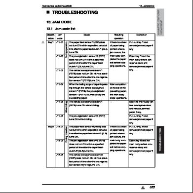
Troubleshooting Bizhub Pro 1050 4y2xf
November 2019 71
Parts Guide Manual Bizhub C552_bizhub C652 g471z
December 2019 147
Firmware Rewriting Bizhub 223 283 363 423 534xx
November 2021 0
Code Cc211 Bizhub 223_283_363_423 5t2g6g
March 2023 0
Troubleshooting Olivetti D-color Mf220_mf280_mf360 17s2c
November 2019 85