Tsci Mistral-air Plus Ma-1100 - Service Manual 2f6j3x
This document was ed by and they confirmed that they have the permission to share it. If you are author or own the copyright of this book, please report to us by using this report form. Report 3b7i
Overview 3e4r5l
& View Tsci Mistral-air Plus Ma-1100 - Service Manual as PDF for free.
More details w3441
- Words: 7,912
- Pages: 46
Technical Manual Mistral-Air® Plus Warming Unit MA1100-EU (220-240V~,50/60Hz) MA1100-US (110-120V~,60Hz) MA1100-JP (100-110V~,50/60Hz)
Beeldschermweg 6 F 3821 AH Amersfoort The Netherlands T: +31(0)33 450 7250 F: +31(0)33 450 7260 [email protected] www.tsci.nl INT/R298-EN/1-11/09
INT/R298-EN/1-11/09
2
Foreword ................................................................................................... 5 Disclaimer ................................................................................................. 5 1 Temperature Management ................................................................. 6 2 Forced Air Warming ........................................................................... 6 3 Description of Mistral-Air® Plus warming unit ................................. 7 3.1 The Appliance ........................................................................... 7 3.2 The Control ..................................................................... 8 3.2.1 Extra Options ..................................................................... 9 3.3 The Blankets ............................................................................. 9 4 Preparing the Mistral-Air® Plus warming unit for use.................... 10 5 Mounting the Mistral-Air® Plus warming unit ................................. 10 6 Instructions.............................................................................. 11 6.1 Connection to Power Supply ................................................... 11 6.2 Activate the Unit ...................................................................... 11 6.3 Connecting the Blanket ........................................................... 12 6.4 Warming up with the Mistral-Air Plus warming unit................ 12 6.4.1 Temperature settings ....................................................... 12 6.4.2 Temperature Selection..................................................... 12 6.5 Stop Warming ......................................................................... 13 7 Maintenance...................................................................................... 14 8 Storage and Cleaning....................................................................... 14 9 Warnings, Precautions and Symbols.............................................. 14 10 Contra-indications............................................................................ 14 11 Safety precautions ........................................................................... 15 12 Symbols ............................................................................................ 15 13 General Description of Hardware.................................................... 19 13.1 Housing ............................................................................... 19 13.2 Top Plate ............................................................................. 19 13.3 Heating System ................................................................... 19 13.4 Blower Motor ....................................................................... 19 13.5 Power Supply & Electronic Hardware .................................. 19 14 Safety Systems and Alarms............................................................. 20 14.1 General Alarms.................................................................... 20 14.2 Other Safety Features ......................................................... 21 15 Temperature & Temperature Alarm Calibration ............................. 21 15.1 Temperature Calibration ...................................................... 21 15.2 Temperature Alarm Calibration............................................ 23 16 Replacing the Filter .......................................................................... 24 17 Reset the Hour Meter ....................................................................... 25 18 Repair Procedures ........................................................................... 25 18.1 Routine Maintenance........................................................... 25 19 Troubleshooting ............................................................................... 26 20 Parts Replacement ........................................................................... 28 20.1 Replacing the Hose ............................................................. 28 20.2 Replacing the Fuses............................................................ 28 INT/R298-EN/1-11/09
3
21
22
23
24
25 26 27
20.3 Replacing the Fan ............................................................... 28 20.4 Replacing the Power Cord................................................... 29 20.5 Record findings at paragraph .............................................. 29 20.6 Replacing the Heater........................................................... 29 After Service Test Protocols............................................................ 30 21.1 Control board test ................................................................ 30 21.2 Set point temperature test ................................................... 30 21.3 Alarm tests .......................................................................... 31 21.4 Electrical safety test............................................................. 32 After Service Test Form ................................................................... 33 22.1 Control Board Test .............................................................. 33 22.2 Set point temperature check................................................ 33 22.3 Alarm tests .......................................................................... 33 22.4 Electrical Safety................................................................... 33 Electromagnetic Compatibility ........................................................ 34 23.1 Electromagnetic immunity.................................................... 34 23.2 Electromagnetic Emissions.................................................. 36 23.3 Recommended Separations Distances................................ 37 Illustrations ....................................................................................... 38 24.1 Disassembly of the Mistral-Air® Plus warming unit............... 38 24.2 Assembly of the Mistral-Air® Plus warming unit. .................. 41 24.3 The Power Controller Board (PCB)...................................... 42 24.4 Wiring Diagram.................................................................... 43 Spare Parts and Order List .............................................................. 44 Warranty............................................................................................ 45 Specifications ................................................................................... 46
INT/R298-EN/1-11/09
4
Foreword Congratulations on your purchase of the Mistral-Air® Plus Forced Air Warming Unit. This device was developed with and for s and was built in accordance to the latest safety standards. We wish you every success in preventing and controlling hypothermia and are sure the Mistral-Air Plus warming unit can help you to do so. Please read this manual carefully before using the Mistral-Air® Plus warming unit. If you identify any improvements and/or discover any other applications during the use of the Mistral-Air® products, please let us know. The Surgical Company International B.V. (TSCI)
Disclaimer All rights reserved. No part of this document may be reproduced or published, electronically, mechanically, in print, photographic print, on microfilm or by any other means whatsoever, without the explicit consent of TSCI. The content of this document has been compiled with the greatest possible care and this information can be regarded as reliable. Nevertheless, TSCI is not liable for any consequences arising from the use of the manual. TSCI reserves the right to make alterations and improvements to the device. These cannot yet be described in the instructions. TSCI B.V. cannot be held liable for the final outcome of the patients’ treatment. This document contains information that may not be published to third parties. This document may not be used without the explicit written consent of TSCI. These instructions are intended for personnel authorised to work with and/or service the medical device mentioned in this manual.
INT/R298-EN/1-11/09
5
1
Temperature Management
Hypothermia, an abnormal drop in body temperature, is a threat to human life. Hospital patients in particular run serious risks if their body temperature falls below 36 ºC. The risk of hypothermia is particularly high at moments when they are vulnerable, such as pre-, per-, and post-surgical interventions. Factors that can contribute to hypothermia include the duration of the surgical intervention, the location of the wound, the amount of blood loss, the surface area of the wound, the environmental temperature and the anaesthetic technique.
2
Forced Air Warming
Forced air warming is a widely used and clinically accepted intervention for the prevention of hypothermia and/or re-warming of the postoperative surgical patient. The principle of operation for forced air warming systems is an electrically powered unit consisting of a fan and heating element that propels warmed air via a flexible hose to a blanket draped over the patient. Some configurations allow for the patient to be placed on top of the blanket or surrounded by a warming tube. All of these forced air warming systems are intended to distribute warmed air to the patient in a manner that is safe and effective.
INT/R298-EN/1-11/09
6
3
Description of Mistral-Air® Plus warming unit
The Mistral-Air® Plus warming unit is a system which is intended for use in preventing patients from getting hypothermic. The Mistral-Air® Plus warming unit should be used with disposable Mistral-Air® blankets that are single patient use only.
3.1
The Appliance Handle, at top side
Control Hose towards patient/blanket
The Mistral-Air® Plus warming unit can be controlled by using the control at the front top of the unit. The clamp to fix the Mistral-Air® Plus warming unit to a stand is positioned at the back of the unit. Article number: - MA1100-EU (220-240V~,50/60Hz) - MA1100-US (110-120V~,60Hz) - MA1100-JP (100-110V~,50/60Hz)
INT/R298-EN/1-11/09
7
3.2
The Control
The control is located at the front top of the unit and can be controlled by pressure sensitive buttons. The Mistral-Air® Plus warming unit is very easy to use. All settings are visible on the control and you can select the preferred temperature by pressing the Temperature Selection button. In emergencies, an audible alarm will be activated and an L.E.D. will flash or glow solid red.
Fan / Ambient air Indicator
Stand-by button
Audible Alarm Suppression button
Temperature Selection Indicator
Temperature Selection button
Service Indicator
Under Temp Over Temp alarm alarm
Explanation of temperature alarm indications: Alarm: An audible alarm is activated and the L.E.D. flashes or glows red. - The primary alarm gives a flashing red L.E.D. - The secondary alarm gives a solid red L.E.D. Cause: There is an over temperature.
Alarm: The L.E.D. flashes red. Cause: There is an under temperature.
INT/R298-EN/1-11/09
8
3.2.1
Extra Options Alarm: The L.E.D. is solid red. Cause: The Mistral-Air® Plus warming unit has been used for ≥ 500 hours and routine maintenance is required. The audible alarm can be suppressed for 3 minutes by button. Audible alarm suppression is pressing the indicated by a solid orange L.E.D. After 3 minutes, the audible alarm will be activated again.
3.3
The Blankets Do not use the Mistral-Air® Plus warming unit with any forced air disposables other than Mistral-Air® blankets. Thermal Injury may result.
Mistral-Air® blankets come in a variety of designs and sizes to meet the customers’ needs for preventing and treating hypothermia. All Mistral-Air® blankets are: Latex free Made from non-woven polypropylene or polyethylene Manufactured to meet flammability standards MR Conditional Not obstructing x-ray Non-conductive Non-sterile, except for several dedicated blankets (ask your distributor) Packed including an insert in the main languages Single-patient use only Made from lightweight, soft materials that have been approved for skin Mistral-Air® blankets need to be used with the soft blue material towards the patient’s skin and the white or reflective layer away from the patient’s skin. The blue side provides the air distribution towards the patient. Never fold the blankets during use Thermal injury may occur if heat is applied to ischemic limbs.
INT/R298-EN/1-11/09
9
4
Preparing the Mistral-Air® Plus warming unit for use Before using the Mistral-Air® Plus warming unit, it should be attached to a stand or placed on a table. Prior to use, the needs to check that the MistralAir® Plus warming unit, the power cord and the hose are undamaged. In the event of damage do not use the Mistral-Air® Plus warming unit. Plug the Mistral-Air® Plus warming unit into an earthed socket.
If required, a safety test in accordance with the hospital protocol will follow.
5
Mounting the Mistral-Air® Plus warming unit
The Mistral-Air® Plus warming unit must be mounted securely before use. The Mistral-Air® Plus warming unit can be mounted onto the Mistral-Air® pole with basket (art. MA5100-B). The unit should be clamped onto the pole with the top of the clamp less than 80 cm above the floor to prevent tipping over. Avoid blocking the air inlet (bottom of unit) It is also possible to place the Mistral-Air® Plus warming unit on a table. Do not place the unit in the bed with the patient. ®
Mistral-Air pole with basket Art. MA5100-B
INT/R298-EN/1-11/09
10
6
Instructions
When using the Mistral-Air® Plus warming unit, the instructions below may be useful.
6.1
Connection to Power Supply
a
b
c
d
a. Make sure the power cord is secured by the cord anchor. b. Plug the unit into an earthed socket. c. The unit automatically switches to Stand-by mode, which is indicated by the orange Stand-by L.E.D. d. The Mistral-Air® Plus warming unit is now in Stand-by mode. To remove all power from the Mistral-Air® Plus warming unit, the mains power cord must be removed from the electrical receptacle.
6.2
Activate the Unit
a
b
c
a. Activate the Mistral-Air® Plus warming unit by pressing the Stand-by button. b. The Mistral-Air® Plus warming unit will now perform a self-test, which includes a flash of all the L.E.D’s and a short audible alarm. c. The Mistral-Air® Plus warming unit will start blowing air at the default temperature setting of 38 ˚C. Do not use the Mistral-Air® Plus warming unit without a Mistral-Air® blanket connected to it. INT/R298-EN/1-11/09
11
6.3
Connecting the Blanket
a
b
c
a. Take the blanket out of the (sterile) package and place it on the patient. b. Unfold the blanket over the patient. c. Insert the end of the flexible hose into the air inlet port of the Mistral-Air blanket. Make sure the hose is fully pushed in. Detailed instructions are mentioned on the inserts delivered with the Mistral-Air blankets.
6.4
Warming up with the Mistral-Air Plus warming unit
6.4.1
Temperature settings
The four settings are: Fan - Ambient air 32 ºC - Low temperature 38 ºC - Medium temperature 43 ºC - High temperature 6.4.2
Temperature Selection
The Mistral-Air® Plus warming unit will start up with the default temperature setting of 38 ºC. By pressing the “–“ button twice, the Mistral-Air® Plus will activate the unit to draw in room temperature air and deliver it to the patient via the blanket. The heater will not be activated. The temperature to the patient will depend on ambient conditions and possible heat from the blower motor. By pressing the “+” of the temperature selection button the Mistral-Air® Plus will activate the heater to deliver the set temperature: 32 ºC, 38 ºC or 43 ºC.
INT/R298-EN/1-11/09
12
By pressing the “+” of the temperature selecting button, the temperature setting increases. This is indicated by a green L.E.D.:
a
c
c
By pressing the “-” of the Temperature Selecting Button, the temperature setting decreases. This is indicated by a green L.E.D.:
a
b
c
After selecting the desired temperature, the L.E.D. below the Temperature Indicator will flash green. After reaching the set temperature (+ 2 ˚C) the flashing L.E.D. will light up permanently.
6.5
Stop Warming
a
b
c
a. Press the Stand-by button b. Disconnect the hose from the blanket c. If desired, leave the blanket on the patient
INT/R298-EN/1-11/09
13
7
Maintenance
The Mistral-Air Plus warming unit has no parts that can be maintained by s. s should not repair or open the Mistral-Air Plus warming unit in the event of a malfunction. This can damage the appliance and will invalidate the guarantee. The hospital service department or the local supplier should service the Mistral-Air® Plus warming unit when the service indicator is activated or at least once a year. Have the Mistral-Air Plus warming unit serial number ready when you the hospital service department or the local supplier for technical . The serial number is located on the bottom of the unit.
8
Storage and Cleaning
Store the Mistral-Air Plus warming unit and accessories in a cool and dry place when not in use. Clean the unit by wiping the outer surface (including the hose) with a soft cloth lightly dampened with a solution of water and mild detergent or a nonstaining hospital disinfectant. Wipe all excess detergent or disinfectant from the unit and allow to air dry. Do not use alcohol or acid base cleaner on the control . Disconnect from power when cleaning the Mistral-Air® Plus warming unit. Do not use dripping wet cloths and do not allow water to seep into electrical areas of the Mistral-Air Plus warming unit.
9
Warnings, Precautions and Symbols
Your Mistral-Air® Plus warming unit was designed and built with safety in mind. The unit should provide reliable service and high quality patient care. However, there is no replacement for care providers being attentive to their patients’ needs and equipment operation. Read and understand all warnings and precautions before using / prescribing the Mistral-Air® Plus warming unit
10
Contra-indications
Do not apply heat directly to open wounds. All patients’ wounds should be covered while using the warming system. Do not apply the warming system to ischemic limbs. Use caution and consider discontinuing use on patients during vascular surgery when an artery is clamped to an extremity (i.e. aortic cross-clamping). Use caution and monitor closely if used on patients with severe peripheral vascular disease. INT/R298-EN/1-11/09
14
11
Safety precautions Grounding reliability can be achieved only when the warming unit is connected to a suitable power outlet. Prevent the blanket material from coming into with a laser or an electrosurgical active electrode; rapid combustion could result. Using other power cords or replacement of parts for internal components than specified by TSCI may result in increased emission or decreased immunity of the Mistral-Air® Plus Warming Unit. When replacing the hose, do not touch the temperature sensors. If these sensors are touched in any way, the unit must be calibrated. (see image in paragraph 20.1) Portable and mobile RF communication equipment can affect the correct functioning of the Mistral-Air® Plus warming unit. The Mistral-Air® Plus warming unit is not suitable for use during magnetic resonance imaging (MRI) scanning. The warming system may affect the MRI image. The Mistral-Air® Plus warming unit is fitted with an air filter; however airborne contamination should be taken into consideration when using the warming system.
12
Symbols
IP21 Rx only
Protected against solid foreign objects of 12.5mm Ø and greater. Protected against vertically falling water drops (according to IEC 60529) Federal US law restricts this device to sale by or on order of a physician (MA1100-US only) With respect to electric shock, fire and mechanical hazards only. In accordance with UL 60601-1/CAN/CSA C22.2 No. 601.1 (MA1100-US only)
INT/R298-EN/1-11/09
15
®
Prior to use, the needs to check that the Mistral-Air Plus warming unit (including the power cord and the hose) is undamaged. In the event of damage do not use the Mistral-Air® Plus warming unit. Connect the Mistral-Air® Plus Warming Unit to an earthed socket only. Risk of electrical shock exists if the equipment is not connected to a properly grounded receptacle. No Free Hosing: do not warm a patient without a Mistral-Air® blanket connected to the unit.
Do not use the Mistral-Air® blankets when damaged. Use forced air warming on monitored patients only. Check patient’s temperature and skin condition at least every 15 minutes.
15 min.
Do not apply to patients with ischemic limbs.
43°C
!
Do not leave the patient unmonitored during forced air warming. Reduce temperature or discontinue therapy when therapeutic goal is reached or if vital signs instability occurs. Avoid blocking the air inlet at the bottom. Do not use Mistral-Air® Plus warming unit and blankets near flammable anaesthetics, to avoid the risk of explosion. Maintenance and repairs should be performed by qualified medical instrument technicians only. To keep the Mistral-Air® Plus warming unit stable, the wheelbase of the stand must be in a particular ratio to the clamp height. See paragraph 5 “. Do not immerse the Mistral-Air® Plus warming unit in fluid. Clean the appliance with standard cleaning agents. See paragraph 8.
INT/R298-EN/1-11/09
16
The Mistral-Air® Plus warming unit is certified according to IEC 60601-1-2 for electromagnetic interference. However, if nevertheless interference effects with different devices occur, the is encouraged to correct the interference by one or more of the following measures: Turn devices in the vicinity off and on to isolate the offending device. Reorient or relocate the other receiving device. Increase the distance between the interfering device and the Mistral-Air® Plus warming unit, use another power socket. If assistance is required, your local dealer. Using other power cords or replacement of parts for internal components than specified by TSCI may result in increased emission or decreased immunity of the unit The Mistral-Air® plus warming unit should not be used adjacent to or stacked with other equipment. Do not use dermal medication on the skin surface where forced air warming is used.
Do not use the Mistral-Air® Plus warming unit with any forced air disposables other than Mistral-Air® blankets. Thermal Injury may result. CE marking of conformity 0344 = identification number of KEMA Quality (Notified Body) (MA1100-EU only) Serial number Article number Sterile, method of sterilisation ethylene oxide Lot number Manufacturer Transport and storage ambient temperature range Transport and storage relative humidity range INT/R298-EN/1-11/09
17
Attention, see the Instructions for Use AC voltage ®
Electrical shock hazard. Do not disassemble the Mistral-Air Plus Warming Unit unless you are a qualified service technician. There are electrically live parts within the unit when it is connected to a power supply. Type BF equipment (according to IEC 60601-1) Equipotentiality
Expiry date, year/month
For single patient use only. Do not re-use.
Latex-free
Transformer fuses (250V 800 mA Fast Acting)
INT/R298-EN/1-11/09
18
13
General Description of Hardware
The Mistral-Air® Plus warming unit comprises plastic enclosure parts, a control , an internal heating element, a fan and electrical components. The unit may be mounted to an IV pole.
13.1
Housing
The Mistral-Air® Plus warming unit housing consists of 5 plastics enclosure parts and an internal steel top plate. To disassemble the unit, see paragraph 24.1
13.2
Top Plate
The Mistral-Air® Plus warming unit top plate frame is made of stainless steel. The top plate is used for fixations of the fan motor and to create an airtight fan space. A U-shaped, silicone profile is used to this function.
13.3
Heating System
The Mistral-Air® Plus warming unit uses a 1000 Watt coiled electric heating element to heat the air it delivers to a blanket.
13.4
Blower Motor
After assembly, the flow rate with a blanket attached is approximately 1.39 m3/min (49 cfm).
13.5
Power Supply & Electronic Hardware
The power cord is customized to country power supply specifications. It shall be fixed at the rear of the Mistral-Air® Plus warming unit. A schematic overview of the Mistral-Air® Plus warming unit is shown in paragraph 24 “Illustrations”.
INT/R298-EN/1-11/09
19
14
Safety Systems and Alarms
The Mistral-Air® Plus warming unit is equipped with visual and audible safety systems to protect against over temperature and under temperature conditions as well as to indicate that routine service is required.
14.1
General Alarms
If equipment emergencies occur, an audible alarm sounds and a led(s) on the control will turn red. These safety systems are described as follows: A. Primary over temperature This flashing red led indicates an over temperature condition of ≥ 46.5 ºC. The solid led will be accompanied by a triple beep with an interval of 25 seconds. These alarms will continue until the temperature falls below 46.5 ºC. Pressing the Audible Alarm Suppression button will suppress the audible alarm for 3 minutes. B. Secondary over temperature This solid red led indicates an over temperature condition of (T primary + 2) – 56.4 ºC. The red led will flash and a short audible alarm sounds. If this occurs, the heater and blower will shutdown and control of the unit will not be restored until the unit is powered off and the internal temperature senor has been cooled down. Pressing the Audible Alarm Suppression button will suppress the audible alarm for 3 minutes. C. Under temperature. This red led indicates an under temperature condition. It is set to activate at 6 ºC under the set temperature. Pressing the Audible Alarm Suppression button will suppress the audible alarm for 3 minutes.
INT/R298-EN/1-11/09
20
14.2
Other Safety Features D. Audible Alarm Suppression. The audible alarm can be suppressed for 3 minutes by pressing the Audible Alarm Suppression button. Audible alarm suppression is indicated by a solid orange led. After 3 minutes, the audible alarm will be activated again. E. Service alarm. When the red led next to the wrench turns red, the Mistral-Air® Plus warming unit has been used for ≥ 500 hours. Routine maintenance including filter replacement is required. After maintenance the meter can be reset (see paragraph 17).
15 15.1
Temperature & Temperature Alarm Calibration Temperature Calibration
The Mistral-Air® Plus warming unit has been calibrated from factory. However, if desired, the unit can be calibrated manually, by following the next few steps. After every adjustment the hose outlet temperature shall be measured/verified according paragraph: 21 After Service Test Protocols
+
+
+
2 sec. a
b
c
d INT/R298-EN/1-11/09
e 21
f
i
g
h
j
k
a) Start in Stand-by mode b) Press and hold simultaneously the “-“ and “+“ buttons followed by pressing the Stand-by button. c) Now the unit is in calibration mode, indicated by a solid green led of the Stand-by button, a flashing green led at the fan Temperature Selection Indicator and a flashing red led at the Service Indicator d) By repetitive pressing the “-“button, scrolling starts towards lower temperature set points e) By repetitive pressing the “+“ button, scrolling starts towards higher temperature set points f) Stop pressing the “-“ or “+“ button at the desired temperature set point and press the Audible Alarm Suppression button to confirm g) After reaching the selected temperature the green flashing led at the selected set point turns into a solid green led h) By pressing the “-“ button, the temperature decreases 0.2 ˚C per press; each 0.2 ˚C adjustment is indicated by a single beep. By pressing the “+“ button, the temperature increases 0.2 ˚C per press; each 0.2 ˚C adjustment is indicated by a single beep. i) By pressing the Audible Alarm Suppression button, another temperature set point can be selected and calibrated by repeating steps d-h. j) The temperature calibration has been completed successfully.
INT/R298-EN/1-11/09
22
15.2
Temperature Alarm Calibration
The Mistral-Air® Plus warming unit under temperature and primary over temperature have been calibrated from factory. However, if desired, these set points can be calibrated manually, by following the next few steps. After every adjustment the hose outlet temperature shall be measured/verified according paragraph 21 After Service Test Protocols
2 sec. a
b
c
d
e
i
INT/R298-EN/1-11/09
f
g
j
k
23
a) Start in Stand-by mode b) Press and hold simultaneously the “-“ and “+“ buttons and the Stand-by button. c) Now the unit is in calibration mode, indicated by a solid green led of the Stand-by button, a flashing green led at the fan Temperature Selection Indicator and a flashing red led at the Service Indicator d) By repetitive pressing the “+“button, scrolling starts towards higher temperature set points (reverse scrolling via the “-“button). Keep pressing till the red under temperature or over temperature alarm led is flashing. e) Stop pressing the “-“or “+“ button at the desired temperature alarm set points and press the Audible Alarm Suppression button to confirm f) The red flashing led at the selected temperature alarm turns into a solid red led g) By pressing the “-“ button, the temperature decreases 0.2 ˚C per press; each 0.2 ˚C adjustment is indicated by a single beep. By pressing the “+“ button, the temperature increases 0.2 ˚C per press; each 0.2 ˚C adjustment is indicated by a single beep. h) By pressing the Audible Alarm Suppression button, another alarm set point can be selected and calibrated by repeating steps d-h. i) The temperature alarm calibration has been completed successfully
16
Replacing the Filter
The accumulation of dust in the air filter can reduce the efficiency of the Mistral-Air® Plus warming unit. The filter should be replaced as alerted by the Service Indicator or when indicated by visual inspection. Only use parts provided by TSCI or your local dealer. 1. For disassembly follow steps 1-7 of paragraph 24.1 2. Insert the new filter with the black seal towards the fan 3. For assembly follow step 1-7 of paragraph 24.1 in reverse order 4. Reset the Hour Meter (see paragraph 17) 5. Execute “After service test protocols” (see paragraph 21) Do not return unit to service without the filter present. The Filter is the only part, which is allowed to be replaced without the need of a biomedical engineer.
INT/R298-EN/1-11/09
24
17
Reset the Hour Meter
The Mistral-Air® Plus warming unit is equipped with a built-in timer that will activate the “Service Indicator” after ≥ 500 hours of use. This is an indication that routine maintenance, including replacement of the filter, is required. After routine maintenance, follow below steps to reset the timer.
+ a
b
c
d
e
f
a) Start in Stand-by mode b) Press and hold simultaneously the “-”, “+“ buttons and the Audible Alarm Suppression button. c) While holding down the buttons, press the Stand-by button. d) Now the service alarm disappears and the unit returns to Stand-by mode e) The hour meter has been reset successfully
18
Repair Procedures
Call your local dealer or TSCI for replacement parts. If you wish to return the unit for examination and repair, please refer to the following section.
18.1
Routine Maintenance
Routine Maintenance should be performed on an annual base or after 500 working hours. At every service interval, please follow the next steps. a) Replace the filter See paragraph 16 b) Reset the hour meter See paragraph 17 c) Perform After Service Test Protocols See paragraph 21 d) Clean the unit if needed -
INT/R298-EN/1-11/09
25
19
Troubleshooting
Problem Possible Cause The unit does Unplugged or not turn on damaged power cord. No power to outlet Poor or loose wire connections.
Action Make sure power cord is plugged in and is undamaged. Replace cord if necessary. Confirm power to outlet. Ensure all connectors and terminals are secure.
Blown fuses at Replace fuse(s) PCB Over temp Poor or loose wire connections to PCB of the heater, alarm and connections. the temperature sensors (2x) and the warming unit inductor. stopped Faulty heater Check resistance of the heater connection to the PCB. Resistance should be 25 – 60 Ω Replace heater if necessary. Faulty temperature sensors
Check resistance of the temperature sensors connection to the PCB. Resistance should be 2.4 – 2.6 KΩ Consult with authorized representative. Faulty inductor Replace Inductor The unit heats Temperature Allow unit to cool from possible overbut turns off (heater/blower heat condition. If condition persists, before housing) maybe check continuity of each temperature reaching the out of calibration. sensor. Consult with authorized set representative. temperature Faulty PCB Consult with authorized representative . Faulty Check resistance of the temperature temperature sensors connection to the PCB. sensors Resistance should be 2.4 – 2.6 KΩ Consult with authorized representative. Obstructed Filter unit has adequate airflow (with or Blower wheel. new filter and blanket attached: 44.4 – 63.1 cfm. Replace filter if necessary and that blower fan spins freely.
INT/R298-EN/1-11/09
26
Problem The unit alarms at too low or too high temperature
Possible Cause Temperature (heater/blower housing) maybe out of calibration. Faulty temperature sensors
Faulty PCB
Action Calibrate the warming unit
Check resistance of the temperature sensors connection to the PCB. Resistance should be 2 – 3 KΩ (room temperature must be between 18-27 °C). Consult with authorized representative. Confirm unit is being used in ambient temperatures (see paragraph 27). Consult with authorized representative.
The unit turns Air inlet obstructed Remove filter and inspect for on but does obstructions. Clean out debris and not blow air replace filter if necessary. Blower wheel is obstructed.
Remove covers and that blower wheel spins freely.
Poor or loose wire Ensure all connectors and terminals are connections secure. Ensure power cord and the base wire harnesses are properly attached to terminal block Faulty PCB The unit turns Faulty or loose on but membrane switch temperature (switch s or settings header). cannot be selected. Faulty control board.
INT/R298-EN/1-11/09
Consult with authorized representative. Remove covers and inspect the membrane connection to the control board. Ensure red/white wire is located at the top. Consult with authorized representative.
27
20
Parts Replacement
The replacement procedures contained herein allow qualified medical equipment persons to repair the Mistral-Air® Plus warming unit. Be sure to your local dealer or TSCI for all your replacement part needs before servicing the unit. Service is available for this Mistral-Air® Plus warming unit: your local dealer or TSCI. High risk of accessible electrically live parts when removing the hose!
20.1
Replacing the Hose
Remove the screw securing the hose at the air outlet of the Mistral-Air® Plus warming unit. Twist the hose from the Mistral-Air® Plus warming unit. Apply the new hose by twisting it firmly into place and apply the screw to secure the hose. Note: when replacing the hose, do not touch the temperature sensors (see images). If these sensors are touched in any way, the unit must be calibrated.
Temperature sensors in hose
20.2
Replacing the Fuses
a) For disassembly follow steps 1-9 of paragraph 24.1 b) Replace fuses c) For assembly follow step 1-9 of paragraph 24.1 in reverse order d) Execute “After service test protocols” (see paragraph 21)
20.3
Replacing the Fan
a) For disassembly follow steps 1-17 of paragraph 24.1 b) Replace the fan c) For assembly follow step 1-17 of paragraph 24.1 in reverse order d) Execute “After service test protocols” (see paragraph 21)
INT/R298-EN/1-11/09
28
20.4
Replacing the Power Cord
a) Unplug the unit b) Remove power cord from back of unit by unlocking the cord anchor:
c) Insert the new power cord and press it firmly into place. d) Lock cord anchor:
20.5
Record findings at paragraph
a) For disassembly follow steps 1-15 of paragraph 24.1 b) Unlock temperature sensor connector from PCB c) Replace temperature sensor d) For assembly follow step 1-15 of paragraph 24.1 in reverse order e) Execute “After service test protocols”
20.6
Replacing the Heater
Due to the technical complexity associated with replacing the motor or the heater, the unit must be returned to your local dealer or TSCI for service.
INT/R298-EN/1-11/09
29
21
After Service Test Protocols
Test conditions: Tests should be executed in an ambient temperature of 22 ±1.5 ˚C. Test set-up Mistral-Air® Plus Warming Unit All tests should be executed by using the Mistral-Air® test equipment (MA2100). The test tube is representing a MA0220 Adult blanket.
The test tube has an own temperature measurement unit (check calibration date).
21.1
Control board test
1 2 3
Switch blower ON Check if all L.E.D.’S blink once and the audible alarm sounds once. Check if after this self-check procedure the blower is in the 38 ˚C heating mode, indicated by the blinking 38 ˚C led at the control ` Select different settings: FAN ONLY, 32, 38 and 43 °C via the control board buttons (5 seconds per temperature set point). Check if the buttons react within 0.5 seconds.
4
Record findings at paragraph 22.1
21.2
Set point temperature test
1 2
Switch blower ON Select 43 °C and wait for stable temperature. (Fluctuation within ±0.5 °C)
INT/R298-EN/1-11/09
30
3 4 5
Check if no low temperature alarm or primary over temperature alarm is enabled (alarm L.E.D. and buzzer) due to possible temperature overshoots Measure the temperature in the test tube (should between 41.5 and 44.5 °C). Repeat steps 3 and 4 at 38 °C and 32 °C (36.5 - 39.5 resp. 30.5 33.5 °C in test tube).
Record findings at paragraph 22.2
21.3
Alarm tests
Low temperature alarm test 1 2 3 4 5 °C. 6
Switch the stand-by button while the audible alarm pressed, and stay holding down the audible alarm button. The ventilator starts and you are able to select between the set points 32, 38 and 43 °C. Scroll via the “-“ or “+“ buttons to 32 °C. Press the audible alarm suppression button to confirm. The heater starts to control the temperature till the 43 °C set point is reached. Then heating is stopped. After + 30 seconds: check if the low temperature alarm is visually and audibly enabled. The tube temperature must be lower than 37 Exit this test mode by switching the blower OFF.
Record findings at paragraph 22.3 Primary over temperature test 1 2 3 4 5 6
Switch the stand-by button while the audible alarm pressed, and stay holding down the audible alarm suppression button. The ventilator starts and you are able to select between the set points 32, 38 and 43 °C. Scroll via the “-“ or “+“ buttons to 38 °C Press the audible alarm suppression button to confirm. The heater will control the temperature till the primary over temperature set point is reached. After few seconds: check if the primary over temperature alarm is visually and audibly enabled (blinking over temperature L.E.D.) Check if the primary temperature alarm is enabled between 46.5 °C and Tsecondary – 2.0 °C.
INT/R298-EN/1-11/09
31
7
Then, heating is stopped automatically till the temperature has dropped to the under temperature alarm value, followed by a second and third heating/cooling cycle. Check if the heater switches OFF after the third cycle. 8 After the test: press the audible alarm suppression button. Check if the audible alarm is disabled. Note: The secondary over temperature alarm shall not be enabled! Record findings at paragraph 22.3 Secondary over temperature test 1 2 3 4 5 6 7 8 9 10 11
Switch the stand-by button while the audible alarm pressed, and stay holding down the audible alarm button The ventilator starts and you are able to select between the set points 32, 38 and 43 °C. Scroll via the “-“ or “+“ buttons to 43 °C Press the audible alarm suppression button to confirm. The heater will control the temperature till the primary over temperature set point is reached. After few seconds: check if the primary over temperature alarm is visually and audibly enabled (blinking over temperature L.E.D.) The unit stays heating. Check if the secondary over temperature alarm is enabled between Tprimary + 2.0 and 56.4 °C (continuous beep, over temperature L.E.D. on). The ventilator and heater are switched off by the alarm circuit. Switch the unit OFF and ON, to go to normal operation. After the test: press at the audible alarm suppression button. Check if the audible alarm is disabled. Switch the blower OFF After cooling, switch the blower ON to check restarting 1.
Record findings at paragraph 22.3
21.4
Electrical safety test
Execute an electrical safety test conform IEC 60601-1, for a class I, BF device. Record findings at paragraph 22.4
INT/R298-EN/1-11/09
32
22
After Service Test Form Hospital Location Serial Number Date Test Engineer Signature
22.1
Control Board Test
L.E.D.’S blinking Audible alarm Switch on at set point 38 °C Button check
22.2
Temperature °C °C °C
Range (°C) 41.5 – 44.5 36.5 – 39.5 30.5 – 33.5
Alarm tests
Selected alarm Low temperature Primary over temperature Secondary over temperature Alarm suppression button
22.4
Fail Fail Fail Fail
Set point temperature check
Selected set point temperature (°C) 43 38 32 Fail Comment …
22.3
Temperature °C °C °C
Range (°C) < 37.0 ≥ 46.5 (Tprimary + 2.0) – 56.4
Electrical Safety
During the electrical safety test, allowable values of continuous leakage and patient auxiliary currents shall be measured, according the following table: Type Body Floating (BF) Allowable values [A] Measured Normal Single Fault Current [A] Condition (NC) Condition (SFC) Earth leakage Fail 500 1000 current general Cabinet Fail 100 500 leakage INT/R298-EN/1-11/09
33
23
Electromagnetic Compatibility
23.1
Electromagnetic immunity
Guidance and manufacture’s declaration - electromagnetic immunity The Mistral-Air® plus warming unit is intended to use in de electromagnetic environment specified below. The customer or the of the Mistral-Air® plus warming unit should assure that it is used in such an environment. Immunity test
IEC60601 test level
Compliance level
Electromagnetic environment guidance
Electromagnetic discharge (ESD)
±6 kV
±6 kV
±8 kV air
±8 kV air
Floors should be wood, concrete or ceramic tile. If floors are covered with synthetic material, the relative humidity should be at least 30%
Electrical fast transient / burst
±2 kV for power supply lines
±2 kV for power supply lines
IEC 61000-4-4
±1kV for input/output lines
±1kV for input/output lines
Surge
±1 kV differential mode
±1 kV differential mode
±2 kV common mode
±2 kV common mode
<5 % UT (>95 % dip in UT ) for 0.5 cycle
<5 % UT (>95 % dip in UT ) for 0.5 cycle
40 % UT (60 % dip in UT ) for 5 cycles
40 % UT (60 % dip in UT ) for 5 cycles
70 % UT (30 % dip in UT ) for 25 cycles
70 % UT (30 % dip in UT ) for 25 cycles
<5 % UT (>95 % dip in UT ) for 5 sec
<5 % UT (>95 % dip in UT ) for 5 sec
IEC 61000-4-2
IEC61000-4-5
Voltage dips, short interruptions and voltage variations on power supply input lines IEC 61000-4-11
INT/R298-EN/1-11/09
Mains power quality should be that of a typical commercial or hospital environment. Mains power quality should be that of a typical commercial or hospital environment. Mains power quality should be that of a typical commercial or hospital environment. If the of the Mistral-Air® plus warming unit requires continued operations during power mains interruptions, it is recommended that the Mistral-Air® plus warming unit be powered from an uninterruptible power supply or a backup battery system. 34
Power frequency (50/60 Hz) magnetic field
3 A/m
3 A/m
IEC 61000-4-8
Power frequency magnetic fields should be at levels characteristic of a typical location in a typical commercial or hospital environment.
NOTE: UT is the a.c. mains voltage prior to application of the test level. Portable and mobile RF communications equipment should not be used no closer to any part of the Mistral-Air® plus warming unit, including cables, than the recommended separation distance calculated from the equation applicable to the frequency of the transmitter. Recommended separation distance Conducted RF IEC61000-4-6
3 Vrms 150 kHz to 80 MHz
3 Vrms
d = 1.2 √ P
Radiated RF IEC61000-4-3
3 V/m 80 MHz to 2.5 GHz
3 V/m
d = 1.2 √ P 80 MHz to 800 MHz d = 2.3 √ P 800 MHz to 2.5 GHz where P is the maximum output power rating of the transmitter in watts (W) according to the transmitter manufacturer and d is the recommended separation distance in meters (m). Field strengths from
INT/R298-EN/1-11/09
35
fixed RF transmitters, as determined by an electromagnetic site surveya, should be less than the compliance level in each frequency b range . Interference may occur in the vicinity of equipment marked with the following symbol:
NOTE 1 At 80 MHz and 800 MHz, the higher frequency range applies. NOTE 2 These guidelines may not apply in all situations. Electromagnetic propagation is affected by absorption and reflection from structures, objects and people. a
Field strengths from fixed transmitters, such as base stations for radio (cellular/cordless) telephones and land mobile radios, amateur radio, AM and FM radio broadcast and TV broadcast cannot be predicted theoretically with accuracy. To assess the electromagnetic environment due to fixed RF transmitters, an electromagnetic site survey should be considered. If the measured filed strength in the location in which the Mistral-Air® plus warming unit is used exceeds the applicable RF compliance level above, the Mistral-Air® plus warming unit should be observed to normal operations. If abnormal performance is observed, additional measures may be necessary, such as reorienting or relocating the Mistral-Air® plus warming unit. b
Over the frequency range 150 kHz to 80 MHz, filed strengths should be less than 3 V/m
23.2
Electromagnetic Emissions
Guidance and manufacture’s declaration – electromagnetic emissions The Mistral-Air® plus warming unit is intended to use in de electromagnetic environment specified below. The customer or the of the Mistral-Air® plus warming unit should assure that it is used in such an environment. Emissions Test
INT/R298-EN/1-11/09
Compliance
Electromagnetic environment – guidance 36
RF emissions
Group 1
The Mistral-Air® plus uses RF energy only for its internal function. Therefore, its RF emissions are very low and are not likely to cause any interference in nearby electronic equipment
Class B
The Mistral-Air® plus is suitable for use in all establishments, including domestic establishments and those directly connected to the public low-voltage power supply network that supplies buildings used for domestic purposes.
CISPR 11
RF emissions CISPR 11 Harmonic emissions
Class A
IEC61000-3-2 Voltage fluctuations/ flicker emissions
Complies
IEC61000-3-3
23.3
Recommended Separations Distances
Guidance and manufacture’s declaration – electromagnetic emissions The Mistral-Air® plus warming unit is intended to use in de electromagnetic environment specified below. The customer or the of the Mistral-Air® plus warming unit should assure that it is used in such an environment. Emissions Test
Compliance
Electromagnetic environment – guidance
RF emissions
Group 1
The Mistral-Air® plus uses RF energy only for its internal function. Therefore, its RF emissions are very low and are not likely to cause any interference in nearby electronic equipment
Class B
The Mistral-Air® plus is suitable for use in all establishments, including domestic establishments and those directly connected to the public low-voltage power supply network that supplies buildings used for domestic purposes.
CISPR 11
RF emissions CISPR 11 Harmonic emissions
Class A
IEC61000-3-2 Voltage fluctuations/ flicker emissions
Complies
IEC61000-3-3 INT/R298-EN/1-11/09
37
24 24.1
Illustrations Disassembly of the Mistral-Air® Plus warming unit.
Step
Description
Image
1
Disconnect the unit from the power outlet
n.a.
2
Place the unit up side down
3
Remove hose screw
4
Twist off hose clockwise
5
Remove screws (3x) of filter screen
INT/R298-EN/1-11/09
38
6
Remove filter screen
7
Remove filter
8
Remove screws (6x) of bottom housing
9
Remove front cover by slightly pulling Note: front cover is made air tight with a silicone sealant, which must be applied when assembling the unit.
10
Place the unit upright
11
Remove screw from PCB
INT/R298-EN/1-11/09
n.a.
39
12 13 14
Disconnect the wiring of the interface Disconnect the wiring of the conductor Disconnect the wiring of the start capacitor
15
Lift upper housing and place beside the unit
See paragraph 0 See paragraph 0 See paragraph 0
For maintenance to the fan and interface please follow the next few steps. 16
Remove screws (6x) of spiral casing cover
17
Remove screws (4x) to release fan
18
Remove screws (7x) to access interface
19
When access to the temperature sensors is required, please ensure the plastic plug is sealed with a suitable sealant.
INT/R298-EN/1-11/09
40
24.2
Assembly of the Mistral-Air® Plus warming unit.
Follow the disassembly steps of paragraph 24.1 in reverse order. When placing back the front cover, below steps must be followed. -
-
Position the front cover as indicated in the picture below. whether the print and cable connectors have been connected correctly (top arrow) Apply a thin layer of silicone (type AA01133) on the border of the front . Only on the left, right and top side (indicated by the line) Place the front on the warming unit whether all 6 clamps (bottom arrow) are locked securely in the warming unit Remove any surplus of silicone with an alcohol swab.
INT/R298-EN/1-11/09
41
24.3
The Power Controller Board (PCB)
Legend: 1 2 3 4 5 6 7 8 9 10 11 12 13
- Keyboard - RS232 connector - Programmer connector main controller processor - Temperature sensor main controller - Programmer connector safety controller processor - Not connected - Temperature sensor safety controller - Not connected - Mains - Heater - Inductor - Start capacitor - Motor
INT/R298-EN/1-11/09
42
24.4
Wiring Diagram
INT/R298-EN/1-11/09
43
25
Spare Parts and Order List Qty.
INT/R298-EN/1-11/09
Part Number
Description
44
26
Warranty
TSCI (‘the manufacturer’) guarantees end-s that, for a period of 3 years from date of dispatch, every Mistral-Air® Plus warming unit will be free of material and finishing defects with normal use and maintenance. The guarantee does not apply to any item that is not produced or approved by the manufacturer, if this item is the cause of the malfunction. The manufacturer has no obligation under this guarantee to perform repairs or replacements resulting partially or in full from accidents, errors, or negligence on the part of the . This guarantee applies only to the use of the Mistral-Air® Plus warming unit in combination with the Mistral-Air® blankets. The use of the Mistral-Air® Plus warming unit in combination with blankets from other manufacturers is only allowed if the blanket manufacturer has proven that such a combination is safe. If this guarantee is utilised, the relevant part should be returned, properly packed, to the local supplier.
INT/R298-EN/1-11/09
45
27
Specifications
Article number GMDN-code and term Dimensions Weight Hose length Power cord length Filtration Voltage Frequency Current Peak power Average power Fuses
MA1100-EU MA1100-US MA1100-JP P 36954 (Heating pad control unit, air) P 36931 (Heating pad, air) 27.6 cm x 38.5 cm x 23.9 cm (l x w x h) + 6.0 kg 1.8 m 4.0 m HEPA, 0.3 µm, 99.99%, H13 conform EN 1822 220-240V~ 110-120V~ 100-110V~ 50/60Hz 60HZ 50/60HZ 3A 6A 8A 950 W 925 W 1000 W 525 W 550 W 625 W 10AT/125V~/ 12.5AT/125V~/ 6.3AT/250V~ 250V~ 250V~ < 50 microamperes
Current leakage Classification 93/42/EEC Class IIb & 2007/47/EC Classification IEC Class I, Body Floating (BF) 60601-1 Classification IEC 60529 IP21 Ground resistance < 0.2 ohm Set point temperature 32ºC, 38ºC or 43ºC Accuracy of temperature + 2ºC Low temperature limit 6 ºC below set point Primary high ≥ 46.5 ºC temperature Limit Secondary high (T primary + 2) – 56.4 ºC temperature Limit Environmental conditions Ambient temperature 10ºC to 40ºC Relative humidity 30 % to 75 % Atmospheric pressure 70 kPa to 106 kPa Transport and storage conditions Ambient temperature - 40ºC to 70ºC Relative humidity 10 % to 90 % (non condensing) Atmospheric pressure 50 kPa to 106 kPa
INT/R298-EN/1-11/09
46
Related Documents 3m3m1z

Tsci Mistral-air Plus Ma-1100 - Service Manual 2f6j3x
November 2019 58
Dataflex Plus Service Manual 9r6x
December 2019 111
Accutorr Plus - Service Manual 39w56
November 2019 53
Olivetti Pr2 Plus Service Manual 62f3o
December 2021 0
Faro Step Plus Service Manual 3t4w3
August 2021 0
St 6000 Plus Service Manual 1ch4v
August 2021 0More Documents from "Lucila Figueroa Gallo" 6f5m5k
Tecme Graphnet Ventilator - Service Manual (es) 6l2s70
April 2020 31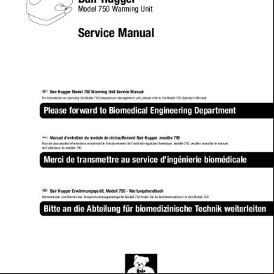
Bair Hugger Model 750 Service Manual English.pdf 5i16j
November 2019 50
Tsci Mistral-air Plus Ma-1100 - Service Manual 2f6j3x
November 2019 58
Manual Stryker Bed 4w2p2s
December 2019 52
Medical Equipment Managment Manual Duke 4972h
October 2021 0