Value Timing Diagram Of Four Stroke Cycle Diesel Engine 5g5z2e
This document was ed by and they confirmed that they have the permission to share it. If you are author or own the copyright of this book, please report to us by using this report form. Report 3b7i
Overview 3e4r5l
& View Value Timing Diagram Of Four Stroke Cycle Diesel Engine as PDF for free.
More details w3441
- Words: 946
- Pages: 5
ME6412
THERMAL ENGINEERING LABORATORY – I 2015
2. VALUE TIMING DIAGRAM OF FOUR STROKE CYCLE diesel ENGINE Exp. No. :
Date:
Aim :
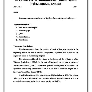
To draw the valve timing diagram of the given four stroke cycle diesel engine.
Apparatus Required : 1. Four stroke diesel engine 2. Measuring tape 3. Chalk 4. Piece of paper. 5. Polar Graph
Theory and Description :
The diagram which shows the position of crank of four stroke engine at the beginning and at the end of suction, compression, expansion and exhaust of the engine are called as valve timing diagram. The extreme position of the piston at the bottom of the cylinder is called “Bottom Dead Centre” [BDC]. In the case of horizontal engine, this is known as “Outer Dead Center”(ODC). The extreme position of the piston at the top of the cylinder is called “Top Dead Centre” (TDC). In the case of horizontal engine this is known as “Inner Dead Centre” (IDC). In an ideal engine, the inlet valve opens at TDC and close at BDC. The exhaust valve opens at BDC and close at TDC. The fuel is ignited when the piston is at TDC at the end of compression stroke. But in actual practice it will differ.
B1 PREPARED BY BIBIN.C and S.GOBINATH, AP/MECH, RMKCET
ME6412
THERMAL ENGINEERING LABORATORY – I 2015
B2 PREPARED BY BIBIN.C and S.GOBINATH, AP/MECH, RMKCET
ME6412
THERMAL ENGINEERING LABORATORY – I 2015
Inlet valve opening and closing : In an actual engine, the inlet valve begins to open 50 to 200 before the piston reaches the TDC during the exhaust stroke. This is necessary to ensure that the valve will be fully open when the piston reaches the TDC. If the inlet valve is allowed to close at BDC, the cylinder would receive less amount of air than its capacity and the pressure at the end of suction will be below, the atmosphere pressure. To avoid this, the inlet valve is kept open for 400 to 500 after the BDC.
Exhaust valve opening and closing : Complete clearing of the burned gases from the cylinder is necessary to take in more air into the cylinder. To achieve this the exhaust valve is open at 250 to 450 before BDC and closes at 100 to 200 after the TDC. It is clear from the diagram, for certain period both inlet valve and exhaust valve remains in open condition. The crank angles for which the both valves are open are called as overlapping period. This overlapping is more than the petrol engine.
Fuel valve opening and closing: The fuel valve opens at 10 to 15 before TDC and closes at 15 to 20 after TDC. This is because better evaporation and mixing fuel.
Procedure: 1. Remove the cylinder head cover and identify the inlet valve exhaust valve and piston of particular cylinder. 2. Mark the BDC and TDC position of flywheel. This is done by Rotating the crank in the usual direction of rotation and observe the position of the fly wheel. When the piston is moving downwards at which the piston, begins to move in opposite direction. i.e from down to upward direction. Make the mark on the flywheel with reference to fixed point on the body of the engine. That point is the BDC for that cylinder. Measure the circumstance of the flywheel and mark the point from BDC at a distance of half of the circumference. That point is TDC and is diametrically opposite to the BDC.
B3 PREPARED BY BIBIN.C and S.GOBINATH, AP/MECH, RMKCET
ME6412
THERMAL ENGINEERING LABORATORY – I 2015
Observation 1. Circumference of flywheel (X ) = ................. cm
Formula used: 1. Crank angle = Distance of flywheel 2. Time duration =
x 360 Circumference
of flywheel
Crank angle displacement 360 x Engine speed in sces
Tabulation:
S.No
Event
Position of crank w.r.to TDC or BDC
1
IVO
Before TDC
2
IVC
After BDC
3
EVO
Before BDC
4
EVC
After TDC
5
FVO
Before TDC
6
FVC
After TDC
Distance from their respective dead centres in „cm‟
Model calculation:
B4 PREPARED BY BIBIN.C and S.GOBINATH, AP/MECH, RMKCET
Angle in degrees
ME6412
THERMAL ENGINEERING LABORATORY – I 2015
3. Insert the paper in the tappet clearance of both inlet and exhaust valves. 4. Slowly rotate the crank until the paper in the tappet clearance of inlet valve is gripped. Make the mark on fly wheel against fixed reference. This position represent the inlet valve open (IVO). Measure the distance from TDC and tabulate the distance. 5. Rotate the crank further, till the paper is just free to move. Make the marking on the flywheel against the fixed reference. This position represent the inlet valve close (IVC). Measure the distance from BDC and tabulate the distance. 6. Rotate the crank further, till the paper in the tappet clearance of exhaust valve is gripped. Make the marking on the flywheel against fixed reference. This position represents the exhaust value open (EVO). Measure the distance from BDC and tabulate it. 7. Rotate the crank further, till the paper in the tappet clearance of exhaust valve is just free to move. Making the marking on the flywheel against fixed reference. This position represents the exhaust valve close (EVC). Measure the distance from TDC and tabulate it. 8. Then convert the measured distances into angle in degrees.
Result: The valve timing diagram for the given four stroke Diesel engine was drawn.
Duration of suction stroke
= ....................
Duration of compression stroke
= ....................
Duration of expansion stroke
= ....................
Duration of exhaust stroke
= ....................
Duration of valve overlap
= ....................
B5 PREPARED BY BIBIN.C and S.GOBINATH, AP/MECH, RMKCET
THERMAL ENGINEERING LABORATORY – I 2015
2. VALUE TIMING DIAGRAM OF FOUR STROKE CYCLE diesel ENGINE Exp. No. :
Date:
Aim :
To draw the valve timing diagram of the given four stroke cycle diesel engine.
Apparatus Required : 1. Four stroke diesel engine 2. Measuring tape 3. Chalk 4. Piece of paper. 5. Polar Graph
Theory and Description :
The diagram which shows the position of crank of four stroke engine at the beginning and at the end of suction, compression, expansion and exhaust of the engine are called as valve timing diagram. The extreme position of the piston at the bottom of the cylinder is called “Bottom Dead Centre” [BDC]. In the case of horizontal engine, this is known as “Outer Dead Center”(ODC). The extreme position of the piston at the top of the cylinder is called “Top Dead Centre” (TDC). In the case of horizontal engine this is known as “Inner Dead Centre” (IDC). In an ideal engine, the inlet valve opens at TDC and close at BDC. The exhaust valve opens at BDC and close at TDC. The fuel is ignited when the piston is at TDC at the end of compression stroke. But in actual practice it will differ.
B1 PREPARED BY BIBIN.C and S.GOBINATH, AP/MECH, RMKCET
ME6412
THERMAL ENGINEERING LABORATORY – I 2015
B2 PREPARED BY BIBIN.C and S.GOBINATH, AP/MECH, RMKCET
ME6412
THERMAL ENGINEERING LABORATORY – I 2015
Inlet valve opening and closing : In an actual engine, the inlet valve begins to open 50 to 200 before the piston reaches the TDC during the exhaust stroke. This is necessary to ensure that the valve will be fully open when the piston reaches the TDC. If the inlet valve is allowed to close at BDC, the cylinder would receive less amount of air than its capacity and the pressure at the end of suction will be below, the atmosphere pressure. To avoid this, the inlet valve is kept open for 400 to 500 after the BDC.
Exhaust valve opening and closing : Complete clearing of the burned gases from the cylinder is necessary to take in more air into the cylinder. To achieve this the exhaust valve is open at 250 to 450 before BDC and closes at 100 to 200 after the TDC. It is clear from the diagram, for certain period both inlet valve and exhaust valve remains in open condition. The crank angles for which the both valves are open are called as overlapping period. This overlapping is more than the petrol engine.
Fuel valve opening and closing: The fuel valve opens at 10 to 15 before TDC and closes at 15 to 20 after TDC. This is because better evaporation and mixing fuel.
Procedure: 1. Remove the cylinder head cover and identify the inlet valve exhaust valve and piston of particular cylinder. 2. Mark the BDC and TDC position of flywheel. This is done by Rotating the crank in the usual direction of rotation and observe the position of the fly wheel. When the piston is moving downwards at which the piston, begins to move in opposite direction. i.e from down to upward direction. Make the mark on the flywheel with reference to fixed point on the body of the engine. That point is the BDC for that cylinder. Measure the circumstance of the flywheel and mark the point from BDC at a distance of half of the circumference. That point is TDC and is diametrically opposite to the BDC.
B3 PREPARED BY BIBIN.C and S.GOBINATH, AP/MECH, RMKCET
ME6412
THERMAL ENGINEERING LABORATORY – I 2015
Observation 1. Circumference of flywheel (X ) = ................. cm
Formula used: 1. Crank angle = Distance of flywheel 2. Time duration =
x 360 Circumference
of flywheel
Crank angle displacement 360 x Engine speed in sces
Tabulation:
S.No
Event
Position of crank w.r.to TDC or BDC
1
IVO
Before TDC
2
IVC
After BDC
3
EVO
Before BDC
4
EVC
After TDC
5
FVO
Before TDC
6
FVC
After TDC
Distance from their respective dead centres in „cm‟
Model calculation:
B4 PREPARED BY BIBIN.C and S.GOBINATH, AP/MECH, RMKCET
Angle in degrees
ME6412
THERMAL ENGINEERING LABORATORY – I 2015
3. Insert the paper in the tappet clearance of both inlet and exhaust valves. 4. Slowly rotate the crank until the paper in the tappet clearance of inlet valve is gripped. Make the mark on fly wheel against fixed reference. This position represent the inlet valve open (IVO). Measure the distance from TDC and tabulate the distance. 5. Rotate the crank further, till the paper is just free to move. Make the marking on the flywheel against the fixed reference. This position represent the inlet valve close (IVC). Measure the distance from BDC and tabulate the distance. 6. Rotate the crank further, till the paper in the tappet clearance of exhaust valve is gripped. Make the marking on the flywheel against fixed reference. This position represents the exhaust value open (EVO). Measure the distance from BDC and tabulate it. 7. Rotate the crank further, till the paper in the tappet clearance of exhaust valve is just free to move. Making the marking on the flywheel against fixed reference. This position represents the exhaust valve close (EVC). Measure the distance from TDC and tabulate it. 8. Then convert the measured distances into angle in degrees.
Result: The valve timing diagram for the given four stroke Diesel engine was drawn.
Duration of suction stroke
= ....................
Duration of compression stroke
= ....................
Duration of expansion stroke
= ....................
Duration of exhaust stroke
= ....................
Duration of valve overlap
= ....................
B5 PREPARED BY BIBIN.C and S.GOBINATH, AP/MECH, RMKCET
Related Documents 3m3m1z
Value Timing Diagram Of Four Stroke Cycle Diesel Engine 5g5z2e
December 2019 98
Valve Timing Diagram Of Four Stroke Cycle Petrol Engine 5i725s
November 2019 109
Valve Timing Diagram On Four Stroke Diesel Engine Model 3x3772
December 2019 48
Port Timing Diagram Of Two Stroke Cycle Petrol Engine 3x446h
December 2019 68
Port Timing Diagram Of Two Stroke Cycle Pertrol Engine 6q6j40
November 2019 42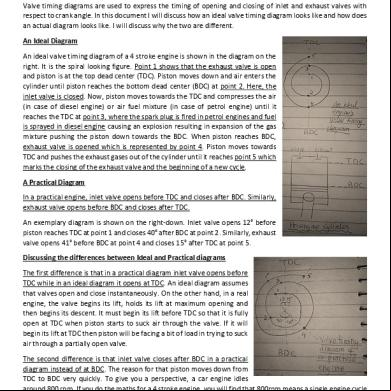
4 Stroke Ic Engine Valve Timing Diagram 1g403i
November 2019 61More Documents from "BIBIN CHIDAMBARANATHAN" 2375p
Value Timing Diagram Of Four Stroke Cycle Diesel Engine 5g5z2e
December 2019 98
Actual Indicator Diagram For A Four Stroke Cycle Diesel Engine.pdf 1i165j
December 2019 91
Me6301 Engineering Thermodynamics - Lecture Notes 5g5v6r
October 2019 71
6l6m1j
November 2019 52
Actual Indicator Diagram For A Two Stroke Cycle Petrol Engine 62c39
November 2019 58