4.1.3.5 Packet Tracer - Configuring Ipv4 And Ipv6 Interfaces Instructions - Ig.pdf 4b5t6h
This document was ed by and they confirmed that they have the permission to share it. If you are author or own the copyright of this book, please report to us by using this report form. Report 3b7i
Overview 3e4r5l
& View 4.1.3.5 Packet Tracer - Configuring Ipv4 And Ipv6 Interfaces Instructions - Ig.pdf as PDF for free.
More details w3441
- Words: 300
- Pages: 2
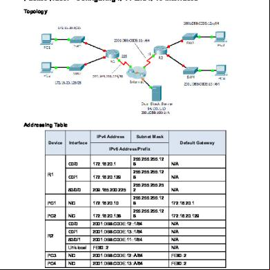
Packet Tracer - Configuring IPv4 and IPv6 Interfaces (Instructor Version) Instructor Note: Red font color or Gray highlights indicate text that appears in the instructor copy only.
Topology
Addressing Table IPv4 Address Device
Subnet Mask
Interface
Default Gateway IPv6 Address/Prefix
G0/0
172.16.20.1
255.255.255.128
N/A
G0/1
172.16.20.129
255.255.255.128
N/A
S0/0/0
209.165.200.225
255.255.255.252
N/A
PC1
NIC
172.16.20.10
255.255.255.128
172.16.20.1
PC2
NIC
172.16.20.138
255.255.255.128
172.16.20.129
G0/0
2001:DB8:C0DE:12::1/64
N/A
G0/1
2001:DB8:C0DE:13::1/64
N/A
S0/0/1
2001:DB8:C0DE:11::1/64
N/A
Link-local
FE80::2
N/A
PC3
NIC
2001:DB8:C0DE:12::A/64
FE80::2
PC4
NIC
2001:DB8:C0DE:13::A/64
FE80::2
R1
R2
Objectives Part 1: Configure IPv4 Addressing and Connectivity
© 2013 Cisco and/or its s. All rights reserved. This document is Cisco Public.
Page 1 of 2
Packet Tracer - Configure IPv4 and IPv6 Interfaces
Part 2: Configure IPv6 Addressing and Connectivity
Background Routers R1 and R2 each have two LANs. Your task is to configure the appropriate addressing on each device and connectivity between the LANs. Note: The EXEC is cisco. The privileged EXEC is class.
Part 1: Configure IPv4 Addressing and Connectivity Step 1: Assign IPv4 addresses to R1 and LAN devices. Referring to the Addressing Table, configure IP addressing for R1 LAN interfaces, PC1 and PC2. The serial interface has already configured.
Step 2: connectivity. PC1 and PC2 should be able to ping each other and the Dual Stack Server.
Part 2: Configure IPv6 Addressing and Connectivity Step 1: Assign IPv6 addresses to R2 and LAN devices. Referring to the Addressing Table, configure IP addressing for R2 LAN interfaces, PC3 and PC4. The serial interface is already configured.
Step 2: connectivity. PC3 and PC4 should be able to ping each other and the Dual Stack Server.
© 2013 Cisco and/or its s. All rights reserved. This document is Cisco Public.
Page 2 of 2
Related Documents 3m3m1z
1.1.3.5 Packet Tracer - Configuring Ipv4 And Ipv6 Interfaces Instructions 165u5i
December 2021 0
4.1.3.5 Packet Tracer - Configuring Ipv4 And Ipv6 Interfaces Instructions 2m2rh
November 2019 76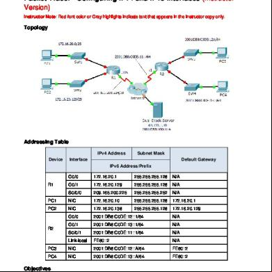
4.1.3.5 Packet Tracer - Configuring Ipv4 And Ipv6 Interfaces Instructions - Ig.pdf 4b5t6h
December 2019 89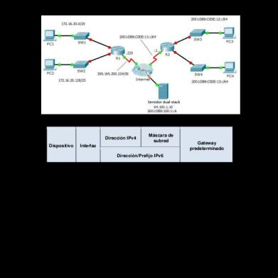
4.1.3.5 Packet Tracer - Configuring Ipv4 And Ipv6 Interfaces Instructions.docx 6l5k1n
September 2021 0
9.5.2.6 Packet Tracer - Configuring Ipv6 Acls Instructions 5u3d4r
April 2021 0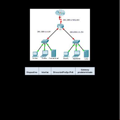
8.2.5.3 Packet Tracer - Configuring Ipv6 Addressing Instructions 2h4x1d
April 2021 0More Documents from "emerson" 5u1m6s

Decibeles-77.pdf j2111
December 2022 0
Servicios En Red Pdf 11243i
April 2023 0
Fundamentos De Computacion Para Ingenieros 525j2m
October 2019 205
Empresa Coaspa Sac Gcia Integral 1hp15
November 2019 81
Eco-ingenieria G2 1 5m1g3i
March 2021 0