Ahu Maintenance 3u4s5x
This document was ed by and they confirmed that they have the permission to share it. If you are author or own the copyright of this book, please report to us by using this report form. Report 3b7i
Overview 3e4r5l
& View Ahu Maintenance as PDF for free.
More details w3441
- Words: 1,982
- Pages: 8
STING – Compact Air Handling Unit Maintenance Instructions
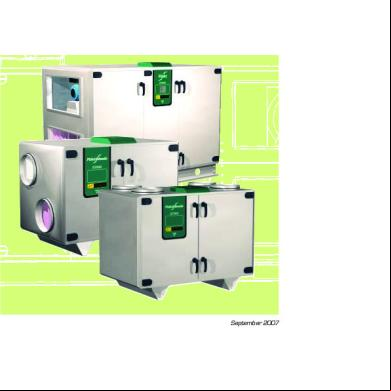
September 2007
STING Air Handling Unit
MAINTENANCE
Safety precautions – General maintenance instructions Service intervals Safety precautions
The service schedule lists the service work necessary for the unit sections that may be included in the air handling unit. The unit contains one or more of these unit sections. Delete from the service schedule the unit sections, which are not included in your particular unit. The date and the initials of the person carrying out the work should be entered on every service occasion. The intervals between service are based on the assumption that the unit is in operation for about 2000 hours per 12-month period in a normal comfort installation. If the supply or extract air has a high dust content, the unit should be serviced more frequently.
WARNING Any open air inlet or outlet unit connections must be fitted with a protective screen before the air handling unit is commissioned. All the electrotechnical and mechanical safety devices must also be installed before the air handling unit can be commissioned Before carrying out any work in the air handling unit, make sure that the power supply to the unit has been isolated. Note that the electric air heater, if installed, has a separate power supply that isn’t isolated across the main switch of the air handling unit. Take great care when opening the venting connections for hot water to the air heater. There is risk of water hammer or escaping steam. Switch off the main switch of the air handling unit before you open the inspection doors to carry out service work or an inspection. All the safety devices shall be refitted at their proper locations before you restart the unit. Open space (backing distance) must be provided in front of the electric air heater and electric equipment cubicle in accordance with local electrical safety regulations. Use the control terminal display when stopping the air handling unit. The inspection doors of the air handling unit are equipped with lockable handles. See to it that the air handling unit inspection doors are locked before you leave the unit and keep the keys inaccessible to unauthorised personnel The inspection doors of filter/fan sections must not be opened while the air handling unit is operating. The fans generate considerable pressure above atmospheric on the doors.
Fläkt Woods
4718 GB 07.10
2
Specifications are subject to alteration without notice
STING Air Handling Unit
MAINTENANCE
Service schedule Applies from 20 .. .. .. t. o. m. 20 .. .. .. 3-monthly / 9-monthly service Symbol
Service work
6-monthly service
Date
Service work Initials
Initials Filter
Check the pressure drop and change the filter, if necessary.
3
12-monthly service Date
Service work Initials
Check the pressure drop and change the filter, if necessary.
Check the pressure drop and change the filter, if necessary.
Clean the rotor
Clean the rotor. Check the monitoring and purging equipment
Carry out visual inspection
Clean the impeller, fan casing and unit casing. Check the bearings.
Date
9 Rotary heat exchanger
Carry out a visual inspection. Check the sealing strips.
3 9
Fan
Carry out visual inspection
3 9
Casing
Check the sealing strips in the doors. Clean the interior, if needed.
3-monthly / 9-monthly service Symbol
Service work
6-monthly service
Date
Service work Initials
Initials Damper
Check the damper performance.
3
12-monthly service Date
Service work Initials.
Check the damper performance.
Clean the damper. Check the damper performance.
Clean the finned coil body and electric heating rods.
Clean the finned coil body, electric heating rods, drip tray and casing
Date
9 Air heater Air cooler
Carry out visual inspection
3 9
Fläkt Woods
4718 GB 07.10
3
Specifications are subject to alteration without notice
STING Air Handling Unit
MAINTENANCE
General maintenance instructions Changing the sealing strip in the inspection door
To dismantle the inspection doors The doors can easily be dismantled by pulling out the pins, Item 3 in Fig. 3.
The sealing strip for the inspection doors is available as a spare part and, if required, must be changed to ensure that the unit is tight.
To adjust the hinges Release the hinge items 1 and 2, and adjust the gaps "A" so that they will be equally wide. Gap "B" should be max. 3 mm. Use a spacer of suitable thickness. Push Items 1 and 2 together and tighten the screws. If threads have been damaged, a blind rivet nut can be used to secure the screw. Check that the sealing strips around the inspection door seal tightly, and that the door is easy to open and close. Also check the operation of the lock.
Spare parts The spare parts and accessories for this air handling unit should be ordered from your nearest Fläkt Woods AB representative. When ordering spares, specify the product codes listed in the Spare Parts Catalogue
To remove individual s
3
2
1
Fig. 3
A
Screw
2 1
Plug Screw
B = max. 3 mm Fig. 1
Screw
To dismantle the Handle A Nut
Locking tongue Plastic washer
2
Rose
1 Bult Handle Lock with key Screw
Fig. 2 Fig. 4. Horizontal unit. Fläkt Woods
4718 GB 07.10
4
Specifications are subject to alteration without notice
STING Air Handling Unit
MAINTENANCE
General maintenance instructions Filter
Fitting new bag filters, sizes 40-85.
As dust is gradually collected in the filter, the flow resistance of the filter will increase accordingly and this will cause a reduction in the air flow. The filter must therefore be changed regularly, at intervals determined by the dust concentration in the air. The maximum permissible pressure drop increase for the class F7 (EU 7) filters supplied with the STING air handling units is 100 Pa.
1) 3)
Indication of when the filter should be changed can be provided by the ETAZ-31 manometer or by an electric impulse from the STYZ-28 filter monitor, for example. The manometer scale should preferably be provided with a red marking at the final pressure drop at which changing of the filter is recommended. Aset of replacement filters should be available for every installation. Replacement filters and spare parts can be ordered from your nearest Fläkt Woods representative.
2)
1)
Fig. 5
Fitting new filters, sizes 10-35.
Press in the lever, 1, of the off-centre locking mechanism, 2, to release the filter cassette. Withdraw the fouled filter. Wipe the surfaces inside the filter space clean. Check that the rubber sealing strips, 3, are undamaged before you fit new filters. No sealing strip is necessary between the cassettes. Carefully insert the new filter cassettes so as not to damage the filter bags. Filter size Fig. 6
Size
Number of filter inserts
Length of the filter inserts
When fitting the filter cassettes, make sure that their rear edge is properly seated in the sealing rail. Insert the filter as indicated by the arrow
Fitting new ultra compact filter, STING Top sizes 20-35.
10
One 592 + 287 mm
300
20
One 392 x 792
360
30, 35
One 892 x 490
547 (360)*
40
Two 592 x 592
547
50
Two 592 x 592 + One 387 x 592
547
65
Three 592 x 592 + Three 287 x 592
547
80, 85
Eight 592 x 592
547
* The filter of an AHU with an air inlet on top is shorter than the filter of an AHU with an end connection frame inlet.
Fig. 7
Fläkt Woods
Place the filter cassettes in the rails. 4718 GB 07.10
5
Specifications are subject to alteration without notice
STING Air Handling Unit
MAINTENANCE
Rotary heat exchanger Rotary heat exchanger
• Supply air fan, right-hand unit/lower level: The rotor rotates downward. Applicable to sizes: 10–85 20–85
• Supply air fan, left-hand unit/upper level: The rotor shall rotate upward. Applicable to sizes: 10–85 20–85 20–35
The rotary heat exchanger is extremely important for the performance and economy of the air handling unit. It is therefore important to keep it clean and in proper working order. The rotor is normally self-cleaning due to the continuously reversing airflow through the rotor as it es into and out of the intermediate plane. The rotor is also equipped with a purging sector that prevents the extract air from being carried over to the supply air as the rotor rotates. It is important for the purging operation that the air pressure in the extract air section is lower (higher subatmospheric pressure) than the air pressure in the supply air section. There should be 0-20 Pa greater sub-atmospheric pressure on the extract air side. This directs the air leakage and the purging air flow toward the extract air and extract air transfer to the supply air can be avoided. Throttling plates located upstream of the extract air filter are utilised for adjusting the pressure differential between the upper and lower levels inside the unit. The direction of rotation of the heat exchanger rotor must also be correct in relation to the location of the supply air fan in the STING air handling unit.
• Supply air fan, left-hand unit/lower level: The rotor shall rotate downward Applicable to sizes 20–85.
• Supply air fan, right-hand unit/upper level: The rotor shall rotate upward. Applicable to sizes: 10–85 20–85 20–35
• Supply air fan, right-hand verticalunit/upper level: The rotor shall rotate right-hand. Applicable to sizes 10–20.
• Supply air fan, left-hand vertical unit/lower level: The rotor shall rotate left-hand. Applicable to sizes10–20.
Fläkt Woods
4718 GB 07.10
6
Specifications are subject to alteration without notice
STING Air Handling Unit
MAINTENANCE
Rotary heat exchanger Sealing strip
The performance of the rotor drive motor should be checked at least once every 6 months. The drive transmission has been lubricated to last throughout its useful life. The rotor shaft bearings are permanently lubricated. Therefore, no subsequent lubrication is necessary. Check that to make sure that the drive belt isn’t slipping or that it hasn’t slipped off the rotor or pulley.
The rotary heat exchanger is equipped with a sealing strip around its periphery and against its intermediate plane for minimising air leakage between the supply air and the extract air sides. Check to make sure that the sealing strip is not damaged along its entire length. Replace if necessary.
To change the drive belt
Face surfaces
Due to wear, it may be necessary to change the drive belt. The original belt has a welded t. The replacement belt is ted together by means of the pin supplied with it. Make sure that the belt has the correct length according to the table below.
Check that the rotor surfaces are not coated with dust. If necessary, clean by vacuum-cleaning or blowing with compressed air from the clean side towards the dust-coated side. If vacuum-cleaning or blowing with compressed air proves inadequate, (if the dust is greasy), clean the rotor surfaces as follows: Spray a degreasing agent [products marked with a SWAN or BRA MILJÖVAL (Good Eco-Choice) are recommended] by hand onto the dust coated-surface of the rotor, and then blow clean with compressed air from the opposite side. As an alternative, the rotor can be cleaned with lowpressure steam or flushed with water if facilities are available for collecting the water. When using a highpressure nozzle to clean the rotor, the jet of water must be aimed at right angles to the rotor structure. The spray nozzle should preferably be held approx. 50 mm from the rotor surface. Suitable pressure: up to 80 bar.
Size
Lenght, mm
10
2036
20
2720
30, 35
3222
40
3928
50
4880
65
5660
80, 85
7540
Caution! Never use acetone or other similarly aggressive liquids
Fläkt Woods
4718 GB 07.10
7
Specifications are subject to alteration without notice
FWG-Sting-GB 2007.09-4718 © Copyright 2006 Fläkt Woods Group Condesign Infocom AB +46 36 30 83 80
Fläkt Woods AB, SE-551 84 Jönköping, Sweden t +46 (0)36-19 30 00 f +46 (0)36-19 36 20 w www.flaktwoods.com
Related Documents 3m3m1z
Ahu Maintenance 3u4s5x
October 2022 0
October 2021 0

Ahu 5w5h4h
February 2021 0
Mcquay Ahu 55q5z
October 2019 48
Ahu Isolation 1d1i5v
February 2022 0
Skm-ahu 6b2x5w
December 2021 0More Documents from "Prakash Mallick" 3bt1k
Ahu Maintenance 3u4s5x
October 2022 0
Siddhar Korakkar's 7 Medical Writings 3mc16
November 2021 0
Astm E 186.pdf 4p4248
December 2019 106
Prodex-tech-en.pdf 2d5d2f
July 2022 0
Gost 380-2005 2cw
November 2019 98