This document was ed by and they confirmed that they have the permission to share it. If you are author or own the copyright of this book, please report to us by using this report form. Report 3b7i
Overview 3e4r5l
& View Maintenance & Troubleshoot Ahu as PDF for free.
More details w3441
- Words: 2,873
- Pages: 11
MAINTENANCE GENERAL REQUIREMENTS
MAINTENANCE PLAN
The maintenance requirements for AHUs are shown below. The procedure is in the left-hand column, and the minimum required frequency is marked is described in the right-hand column.
The following table ( see Table 1) gives recommended maintenance intervals for the air handling unit. Intervals are base upon normal running conditions, in a moderate climate, and assuming 24 hour running. Units operating outside these guideline may require shorter or longer maintenance intervals.
Refer to ANSI/ASHRAE Standard 62.12010 for startup and maintenance practices related to achieving acceptable indoor air quality. This documented program for regular publication of including procedures for timely, documented, consensus action on requests for change to any part of the standard. STANDARD OPERATIONAL PROCEDURES All maintenance and repair process implemented according to prescribed procedures and SOPs : Ø Always coordinative with the leadership in order to generate jobs as efficiently as possible, Ø The scheduled maintenance, schedule equipment and inspection equipment specifications prepared so effective as needed. Ø Completeness of materials that will be used: materials cleaning fluid, cleaning cloth; if necessary, air compressor, inspected and sorted according to the treatment procedure. Ø disassembly tools and measuring devices needed examined in order to work properly and safely
The maintenance interval periods are stated, guidelines only. Any large deviations in the pattern of usage may necessitate further maintenance attention. WARNING Disconnect electrical power and allow rotating parts to stop before servicing the unit. Exercise caution if unit must be on for test or maintenance procedures. Failure to do so may result in injury or death from electrical shock or moving part
WARNING Disconnect electrical power prior to access into fan or ductwork. Even when locked out electrically, fans may cause injury or damage if the impeller is subject to "windmilling". The impeller should be secured to physically restrict rotational movement can cause severe personal injury or death.
PERIODIC MAINTENANCE Checklist The following checklist describes the suggested maintenance schedule to maintain proper operation of the unit. Detailed procedures for owneroperator maintenance checks are given after this checklist After 48 Hours Operation □ Fan and Direct drive Motor their permanent tight. Readjust if not but dont overtighten. Weekly □ Observe unit weekly for any change in running condition and any unusual noise. Every Month Or Weekly □ Check air filters. Clean or replace if clogged or dirty. Change bag filters when pressure drop is till final resistance value. Every Three to Six Months □ Check pulley on fan and motor. □ Tighten electrical connection. □ lnspect coils for dirt build-up or coil freeze up Every Year □ lnspect the unit casing for corrosion. lf damage is found, clean and repaint the surface with a rust-resistant primer and vinyl chlorinated lacquer. □ Clean the fan wheels and fan shaft. Remove rust with emery cloth and apply a coat of LPS#3 or an equivalent. □ lnspect the condensate drain pan and drain line, remove sludge or foreign materials that might obstruct proper drainage. Remove obstacles.
□ Check damper linkages, set-screws and
blade adjustment for proper damper operation. □ lnspect the control and power box wiring for secure connections and insulation. □ Rotate the fan wheel and check for obstruction in the fan housing. The wheel should not rub on the fan housing. Adjust the center if necessary and tighten wheel setscrews to the proper torque. □ Check condition of gasketing and insulation around unit, door and damper. □ Examine flex connections for cracks or leaks. Repair or replace damage material. MAINTENANCE PLAN The following table (see Table 1) gives recommended maintenance intervals for the air handling unit. Intervals are base upon normal running conditions, in a moderate climate, and assuming 24 hour running. Units operating outside these guideline may require shorter or longer maintenance intervals.
Tabel 1 - Recommended Maintenance Intervals Component
Fan and Motor
Filter
Coil
Heater Damper Inlet/outlet drainage quantity of outdoor air in the AHUs Control
Check the following Fan in general Connection Pulley fan Motor in general Pulley motor Clean/ replace Pre filter Check the medium filter Clean/ replace medium filter* Check the Hepa filter Clean/ replace Hepa filter* Visually inspect coils for cleanliness and microbial growth. Fin block/fin bundle Frost Drainage Heater Wiring Damper Hood fresh air Louver Piping drain Drain pans Aiflow Microbial contamination* Control box and wiring Sensor
Weekly
Mounthly
3–6 Mounthly
Annual
*Minimum frequencies may be increased or decreased from what is indicated in this table.
INSPECT PARTS
Hoods And Louvers
Inspect the following parts for damage, dirt and debris.
Inspect the air hoods and louvers for damage and debris. Remove debris as needed.
Cabinet Clean the exterior of the AHU with a mild, environmental safe detergent and highpressure water at 2000 psi.
Fan If Unit not daily operation Fan motors must be operated for at least 2 hours every month to prevent possible fan set failure. The fan infrequently to dirty because material fan is C-pro of Alumunium . Door Hardware Inspect the doors, handles, latches and hinges for proper operation, and the door for damage and if they are properly sealed. Secure any loose parts.
Check for soiling, damage, corrosion, and any tendency to bind. Clean as necessary. Check that the flexible connection are securely fixed. Check the function of all antivibration mounts. Check for any obstructions or blockages of the air intakes and discharges. Check the traps for leaks or blockages and prime as necessary.
s Inspect the s for damage. If the s show signs of excessive pressure change, they will appear to bulge inward or outward. Refer to Troubleshooting on page 78 regarding excessive static pressure. If the needs to be replaced, use the instructions later in this section. If using EC fans, it is possible to reverse these using the designated input signal to
the fan set (view unit specific wiring diagram). The fans will operate as per the 0 – 10 V input signal. To move as much debris as possible, it is advisable to run the fans at the maximum speed the application noise level will allow. For what this voltage will be, with respect to the unit noise level please us for representative. The fans do not need to operate in reverse for longer than 2 minutes to move large debris and some lightly applied particles on the fin surface. Heavier fouling must be removed using a pressure water/steam jet washer (Max pressure 3bar) against direction of airflow, at a distance of 300 to 400mm using a neutral cleaning agent if required. The spray should be even across the coil face and as with a brush, applied in a longitudinal direction across the fins. Motor lnspect periodically for excessive vibration or temperature. Operating conditions will vary the frequency of inspection and lubrication. Dirty motor run hot when thick dirt insulates the frame and clogs cooling air ages. ( motor exterior should be periodically cleaned to remove contaminants that can affect heat dissipation from the motor. Check for signs of corrosion. Lubricate the bearings only when scheduled or if they are noisy or running heat. Do not overl lubricate. Excessive grease and oil captures dirt and can damage bearing. Feel the motor frame and bearing for excessive heat or vibration. Listen for abnormal noise that may indicate a potential motor failure. Promptly identity and eliminate the source of the heat, noise or vibration. that belt and motor drive guards are securely fastened so as not to cause vibration and noise and possible damage to equipment and personnel.
Motor protection is PTC thermistor temperature sensors are predominantly used for thermistor motor protection devices (alarm or shutdown) for motors. These thermistors are generally integrated in the winding overhang. As a consequence, the stator windingis directly protected. The temperature difference between alarm and shutdown (trip) is 10K. When a limit temperature is reached (nominal trippingtemperature), the resistance of PTC thermistors will have a step change. This is evaluated by atrippinunit and can be sued to open auxiliary circuits Dirty motors run hot when thick dirt insulates the frame and clogs cooling air ages. Motor exterior should be periodically cleaned to remove contaminants that can affect heat dissipation from the motor. Check for signs of corrosion : Lubricate the bearings only when scheduled or if they are noisy or running hot. Do not overlubricate. Excessive grease and oil captures dirt and can damage bearings. Feel the motor frame and bearings for excessive heat or vibration. Listen for abnormal noise that may indicate a potential motor failure. Promptly identify and eliminate the source of the heat, noise, or vibration. Air Filters Every month, check the cleanliness of the filters, and if necessary, replace them. Filters should be replaced when the pressure drop, measured by a manometer, reaches the prescribed limits for the installation. Filter types pre filter, medium filter and HEPA filter are the typical filter types as shown in Figure. If your AHU has HEPA
filters, the filter frames, bulkheads and segment s are factory sealed, and must remain sealed for NO air by.
gaskets are normally found filter frame end covers.
on inside of
5. Slide the correct size new filters into tracks. 7. Airflow arrows must point downstream (in direction ofthe airflow). 8.Install all pleated filters with pleats positioned vertically. 9.Reinstall the filter frame end cover.
Fig.1 Prefilter
To clean permanent filters wash under a stream of water to remove dirt and lint. Remove oil filter (aluminum or grease filter) with a wash of mild alkali solution. Rinse in clean, hot water and allow to dry. Coat both sides of the filter by immersing or spraying it with Air Maze Filter Lote W or equivalent. Allow to drain and dry for about 12 hours.
Fig.2 Medium filter Coil Segment Cleaning Coils, whether for heating, dehumidifying, should be internally and externally, and heat transfer should be undamaged.
Fig.3 Hepa filter 1. Check filter sizes anquantities. Refer to the filter label located oneach filter segment. 2. Remove filter frame end cover as shown in Figure 66 on page 66and Figure 67 on page 66. 3. Remove old filters, if present. 4. Make sure gaskets at both ends of the side load filter tracks are in place.The
cooling, or clean both the fins for intact and
Typically, coils (especially cooling coils) are externally cleaned once a year, as this side of the coil receives the most dirt (from the air stream). Coils may be periodically pressure tested for leaks. Control valves wear out over time due to constant modulation. These valves should be included in a regularly scheduled maintenance program. By treating heating steam and heat transfer water, tubes of coils should remain clean, and heat transfer capability should remain high for a number of years.
Steam, hot water and chilled water coils should be kept clean to maintain maximum performance. lf fins become dirty, clean with steam and detergent, hot water spray and detergent, or one of the commercially available chemical coil cleaners. Rinse coils throughly after cleaning.
Direct expansion coils
Never use hot water or steam to clean these coils. During normal opeartion, the fin block must not ice up. If this occurs, check the refrigeration system.
If cleaning coil by periodically, clean dirty coil with water and detergent because just dust and mildew on coil, but if coil have slag slould clean with chemical cleanser. WARNING Follow all directions provided with chemical cleaners to avoid personal injury and/or coil damage. Commercially available chemical cleaners may contain caustic or hazardous agents In the event of coils being out of commission for some time, it is advisable to completely drain down the coil. On each occasion when refilling is undertaken, check that the coil is effectively vented. Periodic cleaning of the coils is required. Dirty coils have increased airside pressure drops and reduced heat transfer,thus unbalancing the cooling or heating system. Cleaning In the event that fin edges have been bent, they can be straightened with the aid of a coil comb. The cleaning is carried out with the unit intact using a powerful vacuum cleaner on the dust-contamainated side. If the unit is very dirty it will need to be removed and wet cleaned. If required, soft cleaning brushes may be used ensuring that the heat exchanger fin are not damaged.
For direct expansion coils, do not use hot water or steam to clean these coils. During normal operation, the fin block must not be ice up. If this occurs, check the refrigeration system. Check that drain pan and drain trap are free from blockage and water accumulation at pan. Refrigerant coils should be kept clean to maintain maximum performance. If fins become dirty, clean with cold water and detergent or one of the commercially available chemicals coil cleaners. Rinse coils thoroughly after cleaning WARNING Never use steam or hot water to clean a refrigerant coil. Dangerous pressures may be built up by improper application of heat resulting in equipment damage oe personal injury.
Damper Prior to occupancy, test ventilation system to ensure that outdoor air dampers operate properly in accordance with the system design.
Check for dirt accumulation, damage and sign of corrosion. Clean with cloth or high pressure air. Check damper blade turning manually or central control for smooth operation. Cleaning procedure Cleaning of dampers should be performed before operation is hindered in any way. Maintenance personnel must determine when cleaning is necessary based on observation and operation. Electric Heater Check for dirt accumulation and clean if necessary with a soft brush. Check the safety control, cables and connections operation. Heat Wheel & Heat Pipe The unit should be maintained in line with the manufacturer recommendation.
TROUBLE SHOOTING Use the table 5 to assist in trouble-shoot the malfunction in Air Handling Unit operation. Table 5 – Trouble Shooting Analysis Symptom
Probable Cause
Motor Fail Start
a) Blown fuse or open circuit a) Replace fuse or reset circuit breaker breaker. b) Improper wiring. b) Check wiring with diagram supplied. c) Mechanical Failure. c) Check motor & drive rotate freely & bearing lubricant. a) Overloaded motor a) Reduce load or replace larger motor. b) Motor Fan dirty/ damage. b) Clean/ replace motor fan.
Motor overheats
Fan does work
Recommended Action
a) No Power Supply / power Failure b) Fan capacitor faulty
a) Check Power supply
c) Fan motor faulty d) Switch faulty
c) Operate when power supply resume d) Replace motor fan / clean
e) Start trip
e) Local dealer
b) Change switch
f) Fuse blown in power switch or operating unit Low air volume after a) Fan rotating in wrong direction. start up b) Air damper not properly set.
a) Reverse any two phase connection at motor terminal. b) Ensure system correctly balance & set. c) Pressure drop by filter above c) Change filters – (complete recommended level. bank). d) Motor fan is clogged with dirt d) Remove fan cover, clean fan preventing proper ventilation and replace cover e) Reduce load or replace with larger motor Air Conditioner works a) thermostat setting too high a) Rest Thermostat but cooling not b) Doors and/or windows not b) Close doors and/or windows satisfactory closed c) Condenser coil dirty c) local dealer d) Some objects blocking the inlet d). Remove the object and/or outlet of the unit e) Indufficient refrigerant charge e) local dealer Note: The table is intended as a diagnostic aid.
Symptom
Probable Cause
Water present in cooling a) Drain trap clog. coil drain pan or b) Incorrect hydraulic trapping overflow Filter collapsing
a) Clean & clear clog.
b) Air velocity too high.
b) Resize trap and check air break arrangement a) Replace at advised dirty condition. b) Check unit running conditions.
Blade bent
Repair or replace blade
Spindle or mechanism loose
Tighting lever fixings
Actuator loose
Refit actuator correctly
a) Filter block with dirt.
Damper seizing
Recommended Action
Low coil capacity Air is by ing coil (Chilled Water) Coil tubes are blocked Incorrect airflow (CFM) Incorrect water flow rate (GPM)
Prevent by with block-off Clean and unblock tubes Check water pumps, valves and lines for obstructions Provide proper water temperature
Incorrect water temperature Low coil (Refrigerant)
capacity Air is by ing coil Coil tubes are blocked
Clean and unblock tubes
Incorrect airflow
Check fan-operating conditions
Expansion valve not operating
Check sensing bulb location and TXV operation Check for blockage in distributor and tube Repair damaged part
Poor refrigerant distribution Leaking Coil
Header / exposed pipe damage Cracks in ts due to strain of pipework on headers Swelling of ts due to frost (Water-hammer Steam Coils)
Drain pan overflow
Wet interior insulation
Prevent bying with block-off
Blockage in trap
Check and alignment of pipework and rectify Check frost protection method and correct, improve Trapping of steaam supply Resize / fit trap and check air break arrangement Clean trap and refit
Plugged Drain Line
Clean drain line
Unit not level
Level unit
Coil face velcity too high
Reduce fan speed
Improper trap design Drain pan leaks / overflows
Design trap per unit installation instructions Repair leaks
Condensation on surfaces
Insulate surfaces
Incorrect hydraulic trapping
Note: The table is intended as a diagnostic aid.
Related Documents 3m3m1z

October 2021 0
Ahu Maintenance 3u4s5x
October 2022 0
Ahu 5w5h4h
February 2021 0
Vmware Troubleshoot 5q2i3x
November 2019 92
Troubleshoot Motor 21363e
April 2020 11
Adfs Troubleshoot 26412z
November 2022 0More Documents from "Eva Sulistiany" 1l273x
October 2021 0
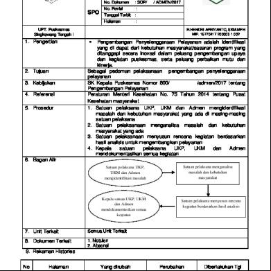
1.1.3. Ep. 1 Sop Penngembangan Dalam Penyelenggaraan Upaya Puskesmas (repaired) k1d2g
April 2020 40
Ethiopian Higher Education Proclamation Pdf 646w2h
January 2022 0
Kerangka Acuan 6p3j3a
December 2020 0
1.1.3.1sop-pengembangan-pelayanan.doc 1c2t15
December 2020 0