Appendix A 65665d
This document was ed by and they confirmed that they have the permission to share it. If you are author or own the copyright of this book, please report to us by using this report form. Report 3b7i
Overview 3e4r5l
& View Appendix A as PDF for free.
More details w3441
- Words: 8,441
- Pages: 42
Hamilton West-Harbour Re-development Designer:_D.Huang, M.Morco_Date:___Jan16th ,2012 :____J. Xing, Y,Liu__ Date:__Feb 23rd,2012
Reference
Appendix A: Sample Calculations Design of Slab: Floor finish 0.08 kPa Ceiling 0.20 kPa Ducts/pipes/wiring 0.25 kPa Non-structural partition 1.10 kPa ---------------------------------------------------------Dead Load 1.63 kPa Live Load (Office) Specified load
= LL +
2.40
kPa
DL = 2.40 +
* 1.63 = 3.8 kPa
The selected composite deck is CD75 - 200 (Galvanneal) Base Steel = 0.914 mm Depth = 130 mm, Maximum specified load = 7.2 kPa> 3.8 kPa Okay Check deflection: DP DC L (beam spacing) Wd =
= 155 kN*m = 360 = 3,200 mm
= 13.14 kPa > 3.8 kPa Okay
Self weight of composite slab = 1.98 kPa
A-1
Agwaymetal INC. Technical data sheet of composite decks www.agway metals.com
Hamilton West-Harbour Re-development Designer:_D.Huang, M.Morco_Date:___Jan16th ,2012 :____J. Xing, Y,Liu__ Date:__Feb 23rd,2012
Snow load Assume flat roof without penthouse S = Is * [Ss(CbCwCsCa) + Sr] Is = 1.0 (Importance factor for snow load) Ss = 0.9 (Ground Snow Load) Sr = 0.4 (1-in-50 year associated rain load) Cb = 0.8 (basic roof snow load factor) Cw = 1.0 (wind exposure factor) Cs = 1.0 (slope factor) Ca = 1.0 (shape factor) S = 1 * (0.9*0.8*1*1*1+0.4) = 1.12kPa
NBCC 2010 – Clause 4.1.6.2 NBCC 2010 Appendix C
Wind uplift NBCC 2010 – Clause 4.1.7.1
Use dead load factor = 0.85 for wind uplift i =0 (For roof) Design roof height = 12.0 m Dead load on the roof, Roof finish 0.15 kPa Steel concrete composite slab 1.98 kPa Insulation 0.10 kPa Steel deck 0.10 kPa Ceiling 0.20 kPa Mechnical system 0.20 kPa Green roof 0.68 kPa ---------------------------------------------------------Dead Load 3.41 kPa
Iw q1/50 Ce Cg
= 1.0 (important factor for wind load) = 0.46 KPa = 0.9 * (h/10)0.2 = 0.93 > 0.9 open terrain ( exposure factor) = 2.0 Building as a whole ( gust effect factor)
H/D = 12/19.8 = 0.606 < 1 Wind Pressure P = Iw (q Ce Cg) 0.46 [ 1.04 * 2 * (-1) ] = 0.46 [ 1.04 * 2 * (-0.5) ] =
Interior Zone : = -0.5 ; End Zone: = -1.0
-0.9542 -0.4771
kPa kPa A-2
Exterior Interior
Hamilton West-Harbour Re-development Designer:_D.Huang, M.Morco_Date:___Jan16th ,2012 :____J. Xing, Y,Liu__ Date:__Feb 23rd,2012
Beam 1 detail design Location: on Axis A from Axis 3 to Axis 6 on the roof Beam spacing = 3.2 m Beam Length = 6.6 m Elasticity of steel = 2.00 E +08 kPa Tributary area = 3.2/2*6.6 = 10.56 m2 Live Load = 1*3.2/2 = 1.6 kN/m Assumed self weight of beam = 0.207 kN/m ( trails done by Excel ) Dead Load = 3.41 * 3.2 /2 +0.207 = 5.66 kN/m Snow Load = 1.12 * 3.2 /2 = 1.79 kN/m Load Combination = 1.25 D + 1.5 S + 0.5 L = 1.25 * 5.66 + 1.5 * 1.79 + 0.5 * 1.6 = 10.56 kN/m
CISC Steel Handbook Pg 5-98
Max shear = 10.56 * 6.6 /2 = 34.9 kN Max moment = 10.56 * 6.6 2/8 = 57.5 kN.m Selection (moment governing ): W310 X 21 Mr = 89.1 kN.m Vr = 303 kN Self weight = 0.207 kN/m Ix = 3.7E+07 mm4
CISC Steel Handbook Pg 5-146
Max deflection due to Live Load : = 5wl4/(384 E Ix) = 5 * 1.6 * 66004 / (384 * 2.00 E +08 * 3.7E+07) *1000 = 5.34 mm < 22 mm ok
A-3
Hamilton West-Harbour Re-development Designer:_D.Huang, M.Morco_Date:___Jan16th ,2012 :____J. Xing, Y,Liu__ Date:__Feb 23rd,2012
Beam 2 detail design Location: on Axis D from Axis 6 to Axis 8 on the roof Beam spacing = 3.2 m Beam Length = 6.6 m Elasticity of steel = 2.00 E +08 kPa Tributary area = 3.2*6.6 = 21.12 m2 LLRF = 0.3 + √ = 0.981 Live Load = 1*3.2 *0.981= 3.14 kN/m Assumed self weight of beam = 0.278 kN/m ( trails done by Excel ) Dead Load = 3.41 * 3.2 +0.278 = 11.19 kN/m Snow Load = 1.12 * 3.2 = 3.58 kN/m
CISC Steel Handbook Pg 5-98
Load Combination = 1.25 D + 1.5 S + 0.5 L = 1.25 * 11.19 + 1.5 * 3.58 + 0.5 * 3.14 = 20.93 kN/m Max shear = 20.93* 6.6 /2 = 69.1 kN Max moment = 20.93 * 6.6 2/8 = 114 kN.m Selection (moment governing ): W310 X 28 CISC Steel Handbook Pg 5-146
Mr = 126 kN.m Vr = 380 kN Self weight = 0.278 kN/m Ix = 5.43E+07 mm4 Max deflection due to Live Load : = 5wl4/(384 E Ix) = 5 * 3.14 * 66004 / (384 * 2.00 E +08 *5.43E+07) *1000 = 7.1 mm < 22 mm ok
A-4
Hamilton West-Harbour Re-development Designer:_D.Huang, M.Morco_Date:___Jan16th ,2012 :____J. Xing, Y,Liu__ Date:__Feb 23rd,2012
Beam 3 detail design Location: on Axis D from Axis 6 to Axis 8 on the 3rd floor slab Beam spacing = 3.2 m Beam Length = 6.6 m Elasticity of steel = 2.00 E +08 kPa Tributary area = 3.2*6.6 = 21.12 m2 LLRF = 0.3 + √ = 0.981 Live Load = 1.9 *3.2 *0.981= 5.97 kN/m Assumed self weight of beam = 0.321 kN/m ( trails done by Excel ) Dead Load = 3.61 * 3.2 +0.321 = 11.87 kN/m Load Combination = 1.25 D + 1.5 L = 1.25 * 11.87 + 1.5 * 5.97 = 23.79 kN/m
CISC Steel Handbook Pg 5-98
Max shear = 23.79* 6.6 /2 = 78.5 kN Max moment = 23.79 * 6.6 2/8 = 129.5 kN.m Selection (moment governing ): W360 X33 Mr = 168 kN.m Vr = 396 kN Self weight = 0.321 kN/m Ix = 8.27E+07 mm4
CISC Steel Handbook Pg 5-146
Max deflection due to Live Load : = 5wl4/(384 E Ix) = 5 * 5.97 * 66004 / (384 * 2.00 E +08 *8.27E+07) *1000 = 8.91 mm < 22 mm ok
A-5
Hamilton West-Harbour Re-development Designer:_D.Huang, M.Morco_Date:___Jan16th ,2012 :____J. Xing, Y,Liu__ Date:__Feb 23rd,2012
Beam 4 detail design Location: on Axis G from Axis 6 to Axis 8 on the 3rd floor slab Beam spacing = 3.2 m Beam Length = 6.6 m Elasticity of steel = 2.00 E +08 kPa Tributary area = 3.2*6.6 = 21.12 m2 LLRF = 0.3 + √ = 0.981 Live Load = (1.9+4.8)/2 *3.2 *0.981= 10.52 kN/m Assumed self weight of beam = 0.321 kN/m ( trails done by Excel ) Dead Load = 3.61 * 3.2 +0.321 = 11.87 kN/m Load Combination = 1.25 D + 1.5 L = 1.25 * 11.87 + 1.5 * 10.52 = 30.62 kN/m
CISC Steel Handbook Pg 5-98
Max shear = 30.62* 6.6 /2 = 101 kN Max moment = 30.62 * 6.6 2/8 = 167 kN.m Selection (moment governing ): W360 X33 Mr = 168 kN.m Vr = 396 kN Self weight = 0.321 kN/m Ix = 8.27E+07 mm4
CISC Steel Handbook Pg 5-146
Max deflection due to Live Load : = 5wl4/(384 E Ix) = 5 * 10.52 * 66004 / (384 * 2.00 E +08 *8.27E+07) *1000 = 15.71 mm < 22 mm ok
A-6
Hamilton West-Harbour Re-development Designer:_D.Huang, M.Morco_Date:___Jan16th ,2012 :____J. Xing, Y,Liu__ Date:__Feb 23rd,2012
Beam 5 detail design Location: on Axis I from Axis 6 to Axis 8 on the 3rd floor slab Beam spacing = 3.2 m Beam Length = 6.6 m Elasticity of steel = 2.00 E +08 kPa Tributary area = 3.2*6.6 = 21.12 m2 LLRF = 0.3 + √ = 0.981 Live Load = 4.8 *3.2 *0.981= 15.07 kN/m Assumed self weight of beam = 0.385 kN/m ( trails done by Excel ) Dead Load = 3.61 * 3.2 +0.385 = 11.94 kN/m Load Combination = 1.25 D + 1.5 L = 1.25 * 11.94 + 1.5 * 15.07 = 37.53 kN/m
CISC Steel Handbook Pg 5-98
Max shear = 37.53* 6.6 /2 = 124 kN Max moment = 37.53 * 6.6 2/8 = 204 kN.m Selection (moment governing ): W410 X39 CISC Steel Handbook Pg 5-146
Mr = 227 kN.m Vr = 480 kN Self weight = 0.385 kN/m Ix = 1.27E+08 mm4 Max deflection due to Live Load : = 5wl4/(384 E Ix) = 5 * 15.07 * 66004 / (384 * 2.00 E +08 *1.27E+08) *1000 = 14.66 mm < 22 mm ok
A-7
Hamilton West-Harbour Re-development Designer:_D.Huang, M.Morco_Date:___Jan16th ,2012 :____J. Xing, Y,Liu__ Date:__Feb 23rd,2012
Beam 6 detail design Location: on Axis A from Axis 3 to Axis 6 on the 3rd floor slab Beam spacing = 3.2 m Beam Length = 6.6 m Elasticity of steel = 2.00 E +08 kPa Tributary area = 3.2*6.6/2 = 10.56 Live Load = 4.8 *3.2 /2= 7.68 kN/m
m2
Assumed self weight of beam = 0.278 kN/m ( trails done by Excel ) Dead Load = 3.61 * 3.2/2 +0.278 = 6.05 kN/m Load Combination = 1.25 D + 1.5 L = 1.25 * 6.05 + 1.5 * 7.68 = 19.09 kN/m
CISC Steel Handbook Pg 5-98
Max shear = 19.09* 6.6 /2 = 63 kN Max moment = 19.09 * 6.6 2/8 = 104 kN.m Selection (moment governing ): W310 X28 Mr = 126 kN.m Vr = 380 kN Self weight = 0.278 kN/m Ix = 5.43E+07 mm4
CISC Steel Handbook Pg 5-146
Max deflection due to Live Load : = 5wl4/(384 E Ix) = 5 * 7.68 * 66004 / (384 * 2.00 E +08 *5.43E+07) *1000 = 17.47 mm < 22 mm ok
A-8
Hamilton West-Harbour Re-development Designer:_D.Huang, M.Morco_Date:___Jan16th ,2012 :____J. Xing, Y,Liu__ Date:__Feb 23rd,2012
Beam 7 detail design Location: on Axis D from Axis 6 to Axis 8 on the 2nd floor slab Beam spacing = 3.2 m Beam Length = 6.6 m Elasticity of steel = 2.00 E +08 kPa Tributary area = 3.2*6.6 = 21.12 m2 LLRF = 0.3 + √ = 0.981 Live Load = 2.4 *3.2 *0.981= 7.54 kN/m Assumed self weight of beam = 0.321 kN/m ( trails done by Excel ) Dead Load = 3.61 * 3.2 +0.321 = 11.87 kN/m Load Combination = 1.25 D + 1.5 L = 1.25 * 11.87 + 1.5 *7.54 = 26.14 kN/m
CISC Steel Handbook Pg 5-98
Max shear = 26.14* 6.6 /2 = 86.3 kN Max moment = 26.14 * 6.6 2/8 = 142.4 kN.m Selection (moment governing ): W360 X33 Mr = 168 kN.m Vr = 396 kN Self weight = 0.321 kN/m Ix = 8.27E+07 mm4 Max deflection due to Live Load : = 5wl4/(384 E Ix) = 5 * 7.54 * 66004 / (384 * 2.00 E +08 *8.27E+07) *1000 = 11.26 mm < 22 mm ok
A-9
CISC Steel Handbook Pg 5-146
Hamilton West-Harbour Re-development Designer:_D.Huang, M.Morco_Date:___Jan16th ,2012 :____J. Xing, Y,Liu__ Date:__Feb 23rd,2012
Beam 8 detail design Location: on Axis G from Axis 6 to Axis 8 on the 2nd floor slab Beam spacing = 3.2 m Beam Length = 6.6 m Elasticity of steel = 2.00 E +08 kPa Tributary area = 3.2*6.6 = 21.12 m2 LLRF = 0.3 + √ = 0.981 Live Load = (2.4+4.8)/2 *3.2 *0.981= 11.3 kN/m Assumed self weight of beam = 0.385 kN/m ( trails done by Excel ) Dead Load = 3.61 * 3.2 +0.385 = 11.94 kN/m Load Combination = 1.25 D + 1.5 L = 1.25 * 11.94 + 1.5 * 11.3 =31.88 kN/m
CISC Steel Handbook Pg 5-98
Max shear = 31.88* 6.6 /2 = 105 kN Max moment = 31.88 * 6.6 2/8 = 174 kN.m Selection (moment governing ): W410 X39 Mr = 227 kN.m Vr = 480 kN Self weight = 0.385 kN/m Ix = 1.27E+08 mm4
CISC Steel Handbook Pg 5-146
Max deflection due to Live Load : = 5wl4/(384 E Ix) = 5 * 11.3 * 66004 / (384 * 2.00 E +08 *1.27E+08) *1000 = 10.99 mm < 22 mm ok
A-10
Hamilton West-Harbour Re-development Designer:_D.Huang, M.Morco_Date:___Jan16th ,2012 :____J. Xing, Y,Liu__ Date:__Feb 23rd,2012
Beam9 detail design Location: on Axis I from Axis 6 to Axis 8 on the 2nd floor slab Tributary area = 6.6 * 1.6 + 6.6 * 1.6 = 21.12 m2 LLRF = 0.3 + √ = 0.981 Live Load = 0.981 * 4.8 * 3.2 = 15.07 kN/m Assume self-weight = 0.385 kN/m ( trails done by excel) Dead Load = 3.2 * 3.5 + 0.385 = 11.94 kN/m Load combination = 1.25 * 11.94 + 1.5 * 15.07 = 37.53
kN/m
Vmax = (wL)/2 = 6.6 * 37.53 / 2 = 124 kN Mmax = (wL2)/2 = 37.53 * 6.62 / 8 = 204 kN*m Selection (moment governing ): W410 X39
CISC Steel Handbook Pg 5-98
Mr = 227 kN.m Vr = 480 kN Self weight = 0.385 kN/m Ix = 1.27E+08 mm4 Deflection: Acceptable deflection = Span / 300 = 6,600 / 300 = 22 mm
CISC Steel Handbook Pg 5-146
Maximum deflection = = 5 * 15.07 * 6,6004 / (384 * 200,000 * 1.27 * 108) = 14.66 mm ok
A-11
Hamilton West-Harbour Re-development Designer:_D.Huang, M.Morco_Date:___Jan16th ,2012 :____J. Xing, Y,Liu__ Date:__Feb 23rd,2012
Beam 10 detail design Location: on Axis A from Axis 3 to Axis 6 on the 2nd floor slab Beam spacing = 3.2 m Beam Length = 6.6 m Elasticity of steel = 2.00 E +08 kPa Tributary area = 3.2*6.6/2 = 10.56 Live Load = 4.8 *3.2 /2= 7.68 kN/m
m2
Assumed self weight of beam = 0.278 kN/m ( trails done by Excel ) Dead Load = 3.61 * 3.2/2 +0.278 = 6.05 kN/m Load Combination = 1.25 D + 1.5 L = 1.25 * 6.05 + 1.5 * 7.68 = 19.09 kN/m CISC Steel Handbook Pg 5-98
Max shear = 19.09* 6.6 /2 = 63 kN Max moment = 19.09 * 6.6 2/8 = 104 kN.m Selection (moment governing ): W310 X28 Mr = 126 kN.m Vr = 380 kN Self weight = 0.278 kN/m Ix = 5.43E+07 mm4 Max deflection due to Live Load : = 5wl4/(384 E Ix) = 5 * 7.68 * 66004 / (384 * 2.00 E +08 *5.43E+07) *1000 = 17.47 mm < 22 mm ok
A-12
CISC Steel Handbook Pg 5-146
Hamilton West-Harbour Re-development Designer:_D.Huang, M.Morco_Date:___Jan16th ,2012 :____J. Xing, Y,Liu__ Date:__Feb 23rd,2012
Girder 1 detail design Location: on Axis 8 from Axis G to Axis J on the roof Girder Length = 3.2 *3 =9.6 m Elasticity of steel = 2.00 E +08 kPa Tributary area = 9.6 *6.6 /2 = 31.68 m2 Transferred Load from Beam to Girder: Concentrated Live Load = 1* 3.2 /2 * 6.6 =10.6 kN Concentrated Dead Load= 3.41 * 3.2 /2 *6.6= 36 kN Concentrated Snow Load = 1.12 * 3.2 /2 *6.6 = 11.83 kN Due to Live Load: Max shear = 10.6 kN Max moment = 10.6 * 3.2 = 33.8 kN.m Due to Dead Load: Assume self weight of girder = 0.454 kN/m ( trails done by excel ) Max shear = ( 0.454 *9.6 + 36 +36)/2 = 38.2 kN Max moment = 0.454*9.62/8+36 * 3.2 = 120.5 kN.m Due to Snow Load: Max shear = 11.83 kN Max moment = 11.83 * 3.2 = 37.8 kN.m Load combination : Max shear = 1.25 D + 1.5 S + 0.5 L = 1.25 * 38.2 + 1.5 * 11.83 + 0.5 * 10.6 = 70.76 kN Max moment = 1.25 D + 1.5 S + 0.5 L = 1.25 * 120.5 + 1.5 * 37.8 + 0.5 * 33.8 = 224.2 kN.m Selection (moment governing ): W410 X 46 Mr= 275 kN.m, Vr= 578 kN, Self weight = 0.454 kN/m Ix = 1.56E+08 mm4 Maximum deflection
=
+
a= 3.2 m , L= 9.6m
=12.24 mm < 32 mm ok
A-13
Hamilton West-Harbour Re-development Designer:_D.Huang, M.Morco_Date:___Jan16th ,2012 :____J. Xing, Y,Liu__ Date:__Feb 23rd,2012
Girder 2 detail design Location: on Axis 6 from Axis G to Axis J on the roof Girder Length = 3.2 *3 =9.6 m Elasticity of steel = 2.00 E +08 kPa Tributary area = 9.6 *6.6 = 63.36 m2 Transferred Load from Beam to Girder: Concentrated Live Load = 1* 3.2 * 6.6 =21.1 kN Concentrated Dead Load= 3.41 * 3.2 *6.6= 72 kN Concentrated Snow Load = 1.12 * 3.2 *6.6 = 23.7 kN Due to Live Load: Max shear = 21.1 kN Max moment = 21.1* 3.2 = 67.6 kN.m Due to Dead Load: Assume self weight of girder = 0.645 kN/m ( trails done by excel ) Max shear = ( 0.645 *9.6 + 72 +72)/2 = 75.1 kN Max moment = 0.645*9.62/8+72* 3.2 = 237.9 kN.m Due to Snow Load: Max shear = 23.7 kN Max moment = 23.7 * 3.2 =75.7 kN.m Load combination : Max shear = 1.25 D + 1.5 S + 0.5 L = 1.25 * 75.1 + 1.5 * 23.7 + 0.5 * 21.1 = 140 kN Max moment = 1.25 D + 1.5 S + 0.5 L = 1.25 * 237.9 + 1.5 * 75.7 + 0.5 * 67.6 = 445 kN.m Selection (moment governing ): W530 X 66 Mr= 484 kN.m, Vr= 928 kN, Self weight = 0.645 kN/m Ix = 3.51E+08 mm4 Maximum deflection
=
+
a= 3.2 m , L= 9.6m
=10.46 mm < 32 mm ok
A-14
Hamilton West-Harbour Re-development Designer:_D.Huang, M.Morco_Date:___Jan16th ,2012 :____J. Xing, Y,Liu__ Date:__Feb 23rd,2012
Girder 3 detail design Location: on Axis 6 from Axis G to Axis J on the 3rd floor slab Girder Length = 3.2 *3 =9.6 m Elasticity of steel = 2.00 E +08 kPa Tributary area = 9.6 *6.6 = 63.36 m2 Transferred Load from Beam to Girder: Concentrated Live Load = 4.8* 3.2 * 6.6 =101.4 kN Concentrated Dead Load= (3.61*3.2+0.385)*6.6= 78.8 kN Due to Live Load: Max shear = 101.4 kN Max moment = 101.4* 3.2 = 324.4 kN.m Due to Dead Load: Assume self weight of girder = 0.997 kN/m ( trails done by excel ) Max shear = ( 0.997 *9.6 + 78.8 +78.8)/2 = 83.6 kN Max moment = 0.997*9.62/8+78.8* 3.2 = 263.6 kN.m Load combination : Max shear = 1.25 D + 1.5 L = 1.25 * 83.6 + 1.5 * 101.4 = 257 kN Max moment = 1.25 D + 1.5 L = 1.25 * 263.6 + 1.5 *324.4 = 816 kN.m Selection (moment governing ): W610 X 101 Mr= 900 kN.m, Vr= 1300 kN, Self weight = 0.997 kN/m Ix = 7.64E+08 mm4 Maximum deflection
=
+
a= 3.2 m , L= 9.6m
=21.56 mm < 32 mm ok
A-15
Hamilton West-Harbour Re-development Designer:_D.Huang, M.Morco_Date:___Jan16th ,2012 :____J. Xing, Y,Liu__ Date:__Feb 23rd,2012
Girder 4 detail design Location: on Axis 8 from Axis G to Axis J on the 3rd floor slab Girder Length = 3.2 *3 =9.6 m Elasticity of steel = 2.00 E +08 kPa Tributary area = 9.6 *6.6 /2 = 31.68 m2 Transferred Load from Beam to Girder: Concentrated Live Load = (4.8* 3.2 /2 * 6.6/2)+ (1.9* 3.2 /2 * 6.6/2)=35.4 kN Concentrated Dead Load= (3.61*3.2+0.321) *6.6/2 = 39.2 kN Due to Live Load: Max shear = 35.4 kN Max moment = 35.4 * 3.2 = 113.2 kN.m Due to Dead Load: Assume self weight of girder = 0.510 kN/m ( trails done by excel ) Max shear = ( 0.510 *9.6 + 39.2 +39.2)/2 = 41.6 kN Max moment = 0.510*9.62/8+39.2 * 3.2 = 131.3kN.m Load combination : Max shear = 1.25 D + 1.5 L = 1.25 * 41.6 + 1.5 * 35.4 = 105 kN Max moment = 1.25 D + 1.5 L = 1.25 * 131.3 + 1.5 * 113.2 = 334 kN.m Selection (moment governing ): W460 X 52 Mr= 338 kN.m, Vr= 680 kN, Self weight = 0.51 kN/m Ix = 2.12E+08 mm4 Maximum deflection
=
+
a= 3.2 m , L= 9.6m
=27.53 mm < 32 mm ok
A-16
Hamilton West-Harbour Re-development Designer:_D.Huang, M.Morco_Date:___Jan16th ,2012 :____J. Xing, Y,Liu__ Date:__Feb 23rd,2012
Girder 5 detail design Location: on Axis 6 from Axis G to Axis J on the 2nd floor slab
Steel Handbook CISC section 6 Pg6-48
Girder Length = 3.2 *3 =9.6 m Elasticity of steel = 2.00 E +08 kPa Tributary area = 9.6 *6.6 = 63.36 m2 Transferred Load from Beam to Girder: Concentrated Live Load = 4.8* 3.2 * 6.6 =101.4 kN Concentrated Dead Load= (3.61*3.2+0.385)*6.6= 78.8 kN Due to Live Load: Max shear = 101.4 kN Max moment = 101.4* 3.2 = 324.4 kN.m Due to Dead Load: Assume self weight of girder = 0.997 kN/m ( trails done by excel ) Max shear = ( 0.997 *9.6 + 78.8 +78.8)/2 = 83.6 kN Max moment = 0.997*9.62/8+78.8* 3.2 = 263.6 kN.m Load combination : Max shear = 1.25 D + 1.5 L = 1.25 * 83.6 + 1.5 * 101.4 = 257 kN Max moment = 1.25 D + 1.5 L = 1.25 * 263.6 + 1.5 *324.4 = 816 kN.m Selection (moment governing ): W610 X 101 Mr= 900 kN.m, Vr= 1300 kN, Self weight = 0.997 kN/m Ix = 7.64E+08 mm4 Maximum deflection
=
+
a= 3.2 m , L= 9.6m
=21.56 mm < 32 mm ok
A-17
Steel Handbook CISC Table D1 Pg 1-134
Hamilton West-Harbour Re-development Designer:_D.Huang, M.Morco_Date:___Jan16th ,2012 :____J. Xing, Y,Liu__ Date:__Feb 23rd,2012
Girder 6 detail design Location: on Axis 8 from Axis G to Axis J on the 2nd floor slab Girder Length = 3.2 *3 =9.6 m Elasticity of steel = 2.00 E +08 kPa Tributary area = 9.6 *6.6 /2 = 31.68 m2 Transferred Load from Beam to Girder: Concentrated Live Load = 2.4* 3.2 * 6.6/2=25.3 kN Concentrated Dead Load= (3.61*3.2+0.321) *6.6/2 = 39.2 kN Due to Live Load: Max shear = 25.3 kN Max moment = 25.3 * 3.2 = 81.1 kN.m Due to Dead Load: Assume self weight of girder = 0.510 kN/m ( trails done by excel ) Max shear = ( 0.510 *9.6 + 39.2 +39.2)/2 = 41.6 kN Max moment = 0.510*9.62/8+39.2 * 3.2 = 131.3kN.m Load combination : Max shear = 1.25 D + 1.5 L = 1.25 * 41.6 + 1.5 * 25.3 = 90.1 kN Max moment = 1.25 D + 1.5 L = 1.25 * 131.3 + 1.5 * 81.1 = 286 kN.m Selection (moment governing ): W460 X 52 Mr= 338 kN.m, Vr= 680 kN, Self weight = 0.51 kN/m Ix = 2.12E+08 mm4 Maximum deflection
=
+
a= 3.2 m , L= 9.6m
=20.1 mm < 32 mm ok
A-18
Hamilton West-Harbour Re-development Designer:_D.Huang, M.Morco_Date:___Jan16th ,2012 :____J. Xing, Y,Liu__ Date:__Feb 23rd,2012
Column 1 detail design Location: at intersection of Axis G and Axis 6 On each floor, two girders and two beams are sitting on , but only half of each member bearing load are transferred to the column Tributary Area = 63.36 m2 LLRF = 0.693 Roof: LL= 43.9 kN DL = 224.1 kN SL= 71 kN Load combination =1.25 D+1.5 S + 0.5 L= 408.5 kN 3rd Floor: LL= 189.6 kN DL= 240.6 kN Load combination =1.25 D+1.5 L=585.2 kN 2nd Floor LL= 184.5 kN DL= 240.8 kN Load combination =1.25 D+1.5 L= 577.79 kN Total Cf = 408.5+ 585.2 + 577.79= 1570 kN Selection: W250X73 KL = 5000 mm Cr = 1680 kN > Cf ok
A-19
Steel Handbook CISC pg 426
Hamilton West-Harbour Re-development Designer:_D.Huang, M.Morco_Date:___Jan16th ,2012 :____J. Xing, Y,Liu__ Date:__Feb 23rd,2012
Column 2 detail design Location: at intersection of Axis G and Axis 8 On each floor, two girders and one beam are sitting on , but only half of each member bearing load are transferred to the column Tributary Area = 31.68 m2 LLRF = 0.856 Roof: LL= 27.1 kN DL = 113.3 kN SL= 35.5 kN Load combination =1.25 D+1.5 S +0.5 L= 208.42 kN 3rd Floor: LL= 104 kN DL= 121 kN Load combination =1.25 D+1.5 L=307.2 kN 2nd Floor LL= 97.6 kN DL= 121.2 kN Load combination =1.25 D+1.5 L= 297.94 kN Total Cf = 208.42+ 307.2 +297.94 = 813 kN Selection: W200X52 KL = 5000 mm Cr = 928 kN > Cf ok
A-20
Steel Handbook CISC pg 426
Hamilton West-Harbour Re-development Designer:_D.Huang, M.Morco_Date:___Jan16th ,2012 :____J. Xing, Y,Liu__ Date:__Feb 23rd,2012
Wind Load Height = 12 m, Width = 48 m p = Iw×q×Ce×Cg× where Iw= 1, q1/50= 0.46 kPa, q1/10 = 0.36, Ce = (H/10)0.2 = 1.037 i = -1 (End Zone) or -0.5 (Interior Zone) Cg = 1.15 – (-1) = 2.15 (End Zone) Cg = 0.75 – (-0.5) = 1.25 (Interior Zone) Wind Pressure (1) Ultimate Limit State End Zone: p = 1×0.46 ×1.037×2.15= 1.026 kPa Interior Zone: p = 1×0.46×1.037×1.25 = 0.596 kPa (2) Serviceability Limit State End Zone: p = 1×0.36 ×1.037×2.15 = 0.803 kPa Interior Zone: p = 1×0.36 ×1.037×1.25 = 0.467 kPa
NBCC 2010 Cl4.1.7.1 Table 4.1.7.1 Appendix C
Wind Surface y = End Zone Width = 0.2×48 = 9.6 m Eccentricity = 48/2 – 9.6/2 = 19.2 m
NBCC Commentary I Figure I-7
Factored Wind Load – End Zone Height of 2nd floor, 3rd floor, and roof 2nd Floor: (5 + 3.5)/2 = 4.25 m 3rd Floor: (3.5 + 3.5)/2 =3.5 m Roof: 3.5 / 2 = 1.75 m Distribution of Lateral Forces (αw = 1.4, load factor for wind load) αw×P1/50 = 1.5 × 1.026 = 1.436 kPa (End Zone) αw×P1/50 = 1.5 × 0.596 = 0.835 kPa (Interior Zone) Sample Calculation for Table 12 wind load summary: At Roof level, At = Total Wind Surface Area = 48 × 1.75 = 84 (m2) Ae = End Zone Surface Area = 9.6 × 1.75 = 16.8 (m2) 0.895 * At = Force in the entire area = 0.835 × 84 = 70.1 (m2) (1.539 – 0.895) * Ae = Additional Force in End Zone = 0.601 × 16.8 =10.1 (m2) Factored Wind Load = 70.1 + 10.1 = 80.2 (kN) Factored Torsion = 10.1 × 19.2 = 193.9 (kN)
A-21
NBCC Commentary I Figure I-7
Hamilton West-Harbour Re-development Designer:_D.Huang, M.Morco_Date:___Jan16th ,2012 :____J. Xing, Y,Liu__ Date:__Feb 23rd,2012
Sample Calculation for Table 13 and Table 14: d = distance between bracing frame to center of rigidity F = Floor force in x or y-direction e = Eccentricity T = Torsion K = relative frame stiffness m = number of frames parallel to F n = number of frames perpendicular to F
i) Bracing frame 3, along grid G3-4, 3rd floor, Wind in South-North Direction The bracing frame is taking both lateral force and torsional force since it is in the same direction as wind load in this case. P = 160.5×1/(1+1) + 387.8×0.095/4.8 = 87.92 kN ii) Bracing frame 3, along G3-4, 3rd floor, Wind in West-East Direction The bracing frame is taking torsional force since it is perpendicular to the direction of wind load in this case. P = 387.8× 0.095/4.8 = 7.69 kN
A-22
Hamilton West-Harbour Re-development Designer:_D.Huang, M.Morco_Date:___Jan16th ,2012 :____J. Xing, Y,Liu__ Date:__Feb 23rd,2012
Mass of each floor Ground level(retails) Interior wall(100 mm hollow block, 5m high) Total horizontal wall length = 70.2 m Total vertical wall length = 97 m
Exterior wall(100 mm hollow block, 5m high) Total horizontal wall length = 47.7 m Total vertical wall length = 24 m
*Note that half of weights from walls in ground level are counted as mass of 2nd level. 2nd level(Office) Slab dead load Floor Finish concrete cover slab and steel deck drop ceiling ducts/pipes/wiring Total
kPa 0.08
Weight(KN) 76
1.98
1881
0.2 0.25 2.51
190 237.5 2384.5
Beams: Grade W310X28 W360X33 W410X39 Total
Quantity(#) Self Weight(kN/m) 6 0.278 24 0.321 18 0.385 48
Length(m) Weight(kN) 6.6 11.01 6.6 50.84 6.6 45.738 108
Girders: Grade W460X52 W610X101 Total
Quantity(#) Self Weight(kN/m) 9 0.510 11 0.997 20
Length(m) Weight(kN) 9.6 44.064 9.6 105.28 149
Columns: Grade W250X73 Total
Quantity(#) Self Weight(kN/m) 24 0.715 24
Length(m) Weight(kN) 3.5 72.93 72.93
A-23
Hamilton West-Harbour Re-development Designer:_D.Huang, M.Morco_Date:___Jan16th ,2012 :____J. Xing, Y,Liu__ Date:__Feb 23rd,2012
Interior walls: 100mm Hollow block
Length(m)
Thickness(m)
Height(m)
Horizontal wall 126.6 0.1 Vertical wall 173.4 0.1 Total 300 Wall density = 1.1 Kpa ( CISC steel handbook pg 7-41) (126.6m*3.5m*1.1kPa)/2+(70.2m*5m*1.1kPa)/2=436.75 kN Exterior walls: 100mm Hollow block Horizontal wall Vertical wall Total
Length(m) 54 24.6 78.6
3.5 3.5
weight( kN) 436.75 600.54 1037
Thickness(m) 0.1 0.1
Height(m) Weight(kN) 3.5 235.13 3.5 113.36 348
Length(m) 0.9 1
Height(m) Weight(kN) 2 17.82 2 3.6 21.42
Length(m) 1.5 1.5
Height(m) Weight(KN) 2 29.4 2 10.5 39.9
Doors: Quantity(#) Hinged Door 33 Sliding Door 6 Total 39 Assumed door density =0.3 kPa Windows: North-south side East-west side Total
Quantity(#) 28 10 38
Total Dead load =2384.5 + 108 +149 + 72.93 + 1037 +348 + 21.42+39.9 =4161 kN Live Load: kPa 2.4 4.8 Total
Tributary Area( m2 ) 570.24 380.16 950
kN 1368.57 1824.76 3193
Total Live Load= 2.4*570.24+4.8*380.16= 3193 kN Seismic weight(D+25%S) = 4161 +0 = 4161kN Total(1.25D+1.5L+0.5S) = 1.25 *4161+1.5*3191+0= 9992 kN A-24
Hamilton West-Harbour Re-development Designer:_D.Huang, M.Morco_Date:___Jan16th ,2012 :____J. Xing, Y,Liu__ Date:__Feb 23rd,2012
Earthquake Load and Effects Equivalent Static Force Procedure IEFaS(0.2) < 0.35 IE = 1.0 (Importance Category - Normal) Fa = 1.0 Sa(0.2) = 0.32 Ta = 0.025hn = 0.30s Sa(0.2) = 0.32, Sa(0.5) = 0.17 By linear interpolation Sa(0.30) = 0.27
Table 4.1.8.5
V = S(Ta)MvIEW/(RdRo) Mv = Higher mode factor (1.0) IE = 1.0 Rd = 3.0 (Moderately ductile concentrically braced frame) Ro = 1.3 W = Total lumped mass from each floor V
NBCC 2010 - Division B Section 4.1.8
= 0.27 * 1.0 * 1.0 * 12,997 / (3 * 1.3) = 900 kN
Table C-2 --Hamilton
Table 4.1.8.9
Distribute the base shear over the height of the structure Fx
= (V-Ft)Wxhx/(∑Wihi)
Ft may be taken as zero when the fundamental period is less than 0.7s For instance, Froof = 900 * 4,537 * 12 / 111,788= 438 kN Accidental Torsion eX = distance between the centre of mass and the centre of rigidity DNX = plan dimension of building at level x perpendicular to the direction of seismic load i) TX = FX * (eX + 0.10 * DNX), and ii) TX = FX * (eX + 0.10 * DNX) For instance, level 3 T3 = Froof * (e3 + 0.10 * DN3) = 438 * ( 0 + 0.10 * 48) = 2,103 kN ii) T3 = FX * (eX - 0.10 * DNX) = 438 * ( 0 - 0.10 * 48) = -2,103 kN i)
A-25
NBCC 4.1.8.11 (10)
Hamilton West-Harbour Re-development Designer:_D.Huang, M.Morco_Date:___Jan16th ,2012 :____J. Xing, Y,Liu__ Date:__Feb 23rd,2012
Torsion Shear A 100kN force was applied at each different level of both the outside and the inside bracing frame on SAP2000.The deflections resulting from each simulation is presented in the table below.
5 L1
10 2X
2X
2X
W460X52 L1 0 52 -1 X 19
10 2
10 2
X1 9-
X1 9-
10
10
W460X52
X L1
0 -1
52
Z
19
Z
2X
10
10
2X 1
2X
9-
5 L1
10
W250X73
5 L1
10 2X
0 -1 19
W250X73
W410X46 L1 52 X
100.00
X
X
BF1 & 4
BF 2 & 3
Ratios
Ratios
u1 (mm)
u1 (mm)
u1/u1
u1/u1
2.0196
2.6888
0.751
1.331
Roof
Force (kN) 100
3rd
100
1.2671
1.5762
0.804
1.244
2nd
100
0.7612
0.9417
0.808
1.237
Level
Since deflection is inversely proportional to rigidity, the ratios obtained from these simulations will be used in the torsion shear calculation. Sample torsion shear calculation for BF1 at roof level: Masonry Structures Behaviour and Design, P-474 Vyir = [xiRyi/Σ(xi2Ryi+yi2Rxi)]exVy Vout = [youtRout/(2xin2Rin+2yout2Rout)]M Since Rin = 0.751 Rout Therfore, VBF1 = -[9.9Rout/(2*4.82*0.751*Rout+2*9.92.Rout)]*2103 VBF1 = -90.27 kN A-26
Hamilton West-Harbour Re-development Designer:_D.Huang, M.Morco_Date:___Jan16th ,2012 :____J. Xing, Y,Liu__ Date:__Feb 23rd,2012
Beam to Girder Connection Girder: W610X101 w=10.5 mm d - 2t = 573 mm
Beam 5: W410X39 w=6.4 mm d - 2t = 381 mm
Bolted to beam web and bolted to both sides of ing member, ed beams not coped, bearing-type.
Web-Framing Legs, Maximum shear for beam W410X39 = 123.8 kN Table 3-37 CISC S16-09
Vertical line with two bolts provides a capacity of: 350 kN> 123.8 kN Okay Web thickness, based on bearing, required for steels with Fu=450 MPa = 8.1 * 123.8 / 350 = 2.87 mm < 6.4 mm Okay Angle thickness required: = 7.7 * 123.8 / 350 = 2.72 mm Minimum Angle length required = 150 mm < 381 mm Okay
Outstanding Legs, Total reaction on girder web is 2 * 123.8 = 247.6 kN For beams connected to both sides of ing member, the bolt capacity is double: 2 * 350 = 700 > 247.6 kN Okay For angle L = 150 mm, W = 76 or 89 mm, two M20 A325M bolts (Bearing-type connections, threads included) per vertical line, the girder web thickness is: 10.5 mm > 8.1 mm Okay Use: 89x89x7.9 connection angles, 150 mm long, two M20 A325M bolts per vertical line in both web-framing and outstanding legs
A-27
Table 3-37 CISC S16-09
Hamilton West-Harbour Re-development Designer:_D.Huang, M.Morco_Date:___Jan16th ,2012 :____J. Xing, Y,Liu__ Date:__Feb 23rd,2012
Check minimum number of bolts Beam: 2 shear planes 1) Shear Resistance of a single bolt. Vr = 0.60ΦbnmAbFu = 0.6 × 0.8 × 1 × 2 × 261 = 250.56 kN
Cl 13.12.1.2(c), Table 3-1
2) Bearing resistance Angle thickness 2t = 2 * 7.94 = 15.88 mm Beam web thickness = 6.4 Governs Br = 3ΦbrntdFu = 3 * 0.8 * 1 * 6.4 *20 * 450 = 138.24 kN 3) Number of bolts = 123.8 / 138.24 = 0.9 < 2 bolts
Cl 13.12.1.2(a)
= Vf / smaller of Brand Vr Okay
Girder: 2 shear planes 4) Shear Resistance of a single bolt. Vr = 0.60ΦbnmAbFu = 0.6 × 0.8 × 1 × 2 × 261 = 250.56 kN 5) Bearing resistance Angle thickness 2t = 2 * 7.94 = 15.88 mm Girder web thickness = 10.5 mm Governs
Cl 13.12.1.2(c), Table 3-1
Br = 3ΦbrntdFu = 3 * 0.8 * 1 * 10.5 *20 * 450 = 226.8 kN 6) Number of bolts = 247.6 / 226.8 = 1. 09 < 4 bolts
= 2* Vf / smaller of Brand Vr Okay
Check tension and shear failure An = [(89 - 60) - 0.5 * (20 + 2) ] * 7.94 = 143 mm2 Agv = (80+35) * 7.94 = 913 mm2 A-28
Cl 13.12.1.2(a)
Hamilton West-Harbour Re-development Designer:_D.Huang, M.Morco_Date:___Jan16th ,2012 :____J. Xing, Y,Liu__ Date:__Feb 23rd,2012
Tr
= Φu[UtAnFu + 0.6Agv(Fy + Fu) / 2] = 0.75(0.6 * 143 * 450 + 0.6 * 913(300 + 450) / 2) = 183 kN> 123.8 kN Okay
Agv
= (80+35 * 2) * 7.94 = 1191 mm2
For one angle
Vr
= Φu[0.6Agv(Fy + Fu) / 2] = 0.75(0.6 * 1191(300 + 450) / 2) = 201 kN> 123.8 kN
Okay
Cl 13.11
Beam to Column Connection Column: W250X73 w=8.6 mm d - 2t = 225 mm
Beam 9: W410X39 w=6.4 mm d - 2t = 381 mm
Bolted to beam web and bolted to both sides of ing member, ed beams not coped, bearing-type. Web-Framing Legs, Maximum shear for beam W410X39 = 123.8 kN
Table 3-37 CISC S16-09
Vertical line with two bolts provides a capacity of: 350 kN> 123.8 kN Okay Web thickness, based on bearing, required for steels with Fu=450 MPa = 8.1 * 123.8 / 350 = 2.87 mm < 6.4 mm Okay Angle thickness required: = 7.7 * 123.8 / 350 = 2.72 mm Minimum Angle length required = 150 mm < 381 mm Okay Outstanding Legs, Total reaction on column web is 2 * 123.8 = 247.6 kN For beams connected to both sides of ing member, the bolt capacity is double: 2 * 350 = 700 > 247.6 kN Okay A-29
Table 3-37 CISC S16-09
Hamilton West-Harbour Re-development Designer:_D.Huang, M.Morco_Date:___Jan16th ,2012 :____J. Xing, Y,Liu__ Date:__Feb 23rd,2012
For angle L = 150 mm, W = 76 or 89 mm, two M20 A325M bolts (Bearing-type connections, threads included) per vertical line, the girder web thickness is: 10.5 mm > 8.1 mm Okay Use: 89x89x7.9 connection angles, 150 mm long, two M20 A325M bolts per vertical line in both web-framing and outstanding legs 88.9 * 2 + 6.4 = 184.2 mm < 225 mm
Okay
Checking, Beam: 2 shear planes 1) Shear Resistance of a single bolt. Cl 13.12.1.2(c), Table 3-1
Vr = 0.60ΦbnmAbFu = 0.6 × 0.8 × 1 × 2 × 261 = 250.56 kN 2) Bearing resistance Angle thickness 2t = 2 * 7.94 = 15.88 mm Beam web thickness = 6.4 Governs
Cl 13.12.1.2(a)
Br = 3ΦbrntdFu = 3 * 0.8 * 1 * 6.4 *20 * 450 = 138.24 kN 3) Number of bolts = 123.8 / 138.24 = 0.9 < 2 bolts
= Vf / smaller of Brand Vr Okay
Column: 2 shear planes 4) Shear Resistance of a single bolt. Vr = 0.60ΦbnmAbFu = 0.6 × 0.8 × 1 × 2 × 261 = 250.56 kN
Cl 13.12.1.2(c), Table 3-1
5) Bearing resistance Angle thickness 2t = 2 * 7.94 = 15.88 mm Column web thickness = 8.6 mm Governs A-30
Hamilton West-Harbour Re-development Designer:_D.Huang, M.Morco_Date:___Jan16th ,2012 :____J. Xing, Y,Liu__ Date:__Feb 23rd,2012
Br = 3ΦbrntdFu = 3 * 0.8 * 1 * 8.6 *20 * 450 = 185.76 kN 6) Number of bolts = 247.6 / 185.76 = 1.33 < 4 bolts
Cl 13.12.1.2(a)
= 2* Vf / smaller of Brand Vr Okay
Check tension and shear failure An = [(89 - 60) - 0.5 * (20 + 2) ] * 7.94 = 143 mm2 Agv = (80+35) * 7.94 = 913 mm2 Tr
= Φu[UtAnFu + 0.6Agv(Fy + Fu) / 2] = 0.75(0.6 * 143 * 450 + 0.6 * 913(300 + 450) / 2) = 183 kN> 123.8 kN Okay
Agv
= (80+35 * 2) * 7.94 = 1191 mm2
Vr
= Φu[0.6Agv(Fy + Fu) / 2] = 0.75(0.6 * 1191(300 + 450) / 2) = 201 kN> 123.8 kN
For one angle Cl 13.11
Okay
Girder to Column Connection Column: W250X73 tf=14.2 mm d - 2t = 225 mm
Girder 9: W610X101 w=10.5 mm d - 2t = 573 mm
Bolted to beam web and bolted to both sides of ing member, ed beams not coped, bearing-type. Web-Framing Legs, Table 3-37 CISC S16-09
Maximum shear for girder W610X101 = 256.5 kN Vertical line with two bolts provides a capacity of: 350 kN> 256.5 kN Okay Web thickness, based on bearing, required for steels with Fu=450 MPa = 8.1 * 256.5 / 350 = 5.94 mm < 10.5 mm Okay A-31
Hamilton West-Harbour Re-development Designer:_D.Huang, M.Morco_Date:___Jan16th ,2012 :____J. Xing, Y,Liu__ Date:__Feb 23rd,2012
Angle thickness required: = 7.7 * 256.5 / 350 = 5.64 mm Minimum Angle length required = 150 mm < 573 mm Okay Outstanding Legs, For girders connected to column flange, the bolt capacity is: 350 > 256.5 kN Okay
Table 3-37 CISC S16-09
For angle L = 150 mm, W = 76 or 89 mm, two M20 A325M bolts (Bearing-type connections, threads included) per vertical line, the column flange thickness is: 14.2 mm > 8.1 mm Okay Use: 89x89x13 connection angles, 150 mm long, two M20 A325M bolts per vertical line in both web-framing and outstanding legs
Check minimum number of bolts Girder: 2 shear planes 1) Shear Resistance of a single bolt. Cl 13.12.1.2(c), Table 3-1
Vr = 0.60ΦbnmAbFu = 0.6 × 0.8 × 1 × 2 × 261 = 250.56 kN 2) Bearing resistance Angle thickness 2t = 2 * 12.7 = 25.4 mm Girder web thickness = 10.5 Governs
Cl 13.12.1.2(a)
Br = 3ΦbrntdFu = 3 * 0.8 * 1 * 10.5 *20 * 450 = 226.8 kN 3) Number of bolts = 256.5 / 226.8 = 1.13 < 2 bolts
= Vf / smaller of Brand Vr Okay
Column: 1 shear plane 4) Shear Resistance of a single bolt. A-32
Hamilton West-Harbour Re-development Designer:_D.Huang, M.Morco_Date:___Jan16th ,2012 :____J. Xing, Y,Liu__ Date:__Feb 23rd,2012
Vr = 0.60ΦbnmAbFu = 0.6 × 0.8 × 1 × 1 × 261 = 125.28 kN Cl 13.12.1.2(c), Table 3-1
5) Bearing resistance Angle thickness t = 12.7 mm Governs Column flange thickness = 14.2 mm Br = 3ΦbrntdFu = 3 * 0.8 * 1 * 12.7 *20 * 450 = 274 kN 6) Number of bolts = 256.5 / 125.28 = 2.05 < 4 bolts
Cl 13.12.1.2(a)
= Vf / smaller of Brand Vr Okay
Check tension and shear failure An = [(89 - 60) - 0.5 * (20 + 2)] * 12.7 = 228.6 mm2 Agv = (80+35) * 12.7 = 1460.5 mm2 Tr
= Φu[UtAnFu + 0.6Agv(Fy + Fu) / 2] = 0.75(0.6 * 228.6 * 450 + 0.6 * 1460.5(300 + 450) / 2) = 292.8 kN> 256.5 kN Okay
Agv
= (80+35 * 2) * 12.7 = 1905 mm2
Vr
= Φu[0.6Agv(Fy + Fu) / 2] = 0.75(0.6 * 1905(300 + 450) / 2) = 321.5 kN> 256.5 kN
For one angle
Cl 13.11 Okay
A-33
Hamilton West-Harbour Re-development Designer:_D.Huang, M.Morco_Date:___Jan16th ,2012 :____J. Xing, Y,Liu__ Date:__Feb 23rd,2012
Slab to Beam Connection Composite Slab Selection: CD75-200(Galvanneal)1 Base steel = 0.914 mm, slab depth= 130mm. be yc
CISC, Cl.17.4.1
= 0.25 * 6600 = 1650 mm = (фs Asfy) / (0.85 фcf’c be) фs = 0.85 As = 4990 mm2 fy = 350 MPa фc = 0.65 f’c = 25 MPa yc
CISC P6-48
= (0.9 * 4990 * 350) / 0.85 * 0.65 * 25 * 1650 = 69.0 mm
Ycis less than the depth of the concrete 130 mm, therefore the neutral axis lies in concrete Qr = Nqrs N = (0.85 фcf’c b yc * 40%) / qrs qrs N
Spacing:
= 32.3 kN - ( 12.7 mm)
CISC TABLE 5-2
= (0.85 * 0.65 * 25 * 1650 * 69 *0.4) / 32300 = 20 studs S = 6600 / (20 / 2) = 660 mm ( Two studs per row )
1
Retrieved from Agway Metals Inc.http://www.agwaymetals.com/products_decking.asp
A-34
Hamilton West-Harbour Re-development Designer:_D.Huang, M.Morco_Date:___Jan16th ,2012 :____J. Xing, Y,Liu__ Date:__Feb 23rd,2012
Lateral Bracing System Connections Factored shear resistance of bolt: Vr = 0.60фbnmAbFu Since Vf = 522kN 522,000N = 0.60 x 0.8 x 2 x2xAbx830MPa Ab = 328 mm2 Therefore, structural bolt M22 is chosen with an Ab of 380 mm2
CISC CSA S16-09, Cl.13.12.1.2 (c)
Factored bearing resistance at bolt holes: Br = 3фbrntdFu Br = 3x0.8x2x10x22x450MPa = 475kN< 522kN Therefore, structural bolt M27 is chosen instead of M22. Br = 3x0.8x2x10x27x450MPa = 583 kN
CISC CSA S16-09, Table 3-1 CISC CSA S16-09, Cl.13.12.1.2 (a)
Factored tensile resistance: Double angle: Tr = фuAneFu Tr = 0.75x[19x(152-(2x27))]x450 = 628kN 2 angles x 628kN = 1256 kN> 428kN
CISC CSA S16-09, Cl.13.2
Double angle: Tr = фu[UtAnFu+0.6Agv(Fy+Fu)/2] Tr = 0.75[0.6x76x19x450+0.6x150x19(350+450)/2] = 805 kN 2 angles x 805 kN = 1610 kN> 428kN
CISC CSA S16-09, Cl.13.11
Plate: Tr = фu[UtAnFu+0.6Agv(Fy+Fu)/2] Tr = 0.75[1x75x10x450+0.6x75x10(350+450)/2] = 388 kN> 428*0.707 =300 kN Therefore, double angle L152x102x16 with two structural bolts M27 at each beam or column connection is sufficient to resist the factored loads.
A-35
Hamilton West-Harbour Re-development Designer:_D.Huang, M.Morco_Date:___Jan16th ,2012 :____J. Xing, Y,Liu__ Date:__Feb 23rd,2012
Column to Column Connections Use 20M A325M bolts d = 20mm, Ab = 314mm2 Bearing Capacity Girder W610X101, Column 250X73 Br = 3ΦbntdFu = 3×0.8×2×14.9×20×450 = 644 kN
CSA S16-09 Table 3-1
Shear Resistance of a single bolt Vr = 0.6ΦbnmAbFu = 0.6×0.8×2×1×261 = 250.56 kN (governs) Max axial load on Column = 585.2 kN ( page A-19 Column 1 design) # of bolts required = 585.2 / 250.56 = 2.3 bolts
Cl 13.12.1.2 (a) CL 13.12.1.2 (c)
Use 4 bolts ( 2 per row) for construction purpose Spacing: Min. pitch (center to center) = 2.7×20 = 54 mm Min. edge distance = 34 mm Max. edge distance = 12 × thickness of the outside connected part BUT LESS THAN 150mm Cl 22.3.1 Cl 22.3.2 Table 6 – shared edge)
A-36
Hamilton West-Harbour Re-development Designer:_D.Huang, M.Morco_Date:___Jan16th ,2012 :____J. Xing, Y,Liu__ Date:__Feb 23rd,2012
Green Roof Load Calculation: Roof Area: Calculation uses loose soil, which has approximately 1000 kg/m3 Soil volume for green roof: 623.5 m2(0.3m) = 187.1 m3 Total soil weight: 187.1m3(1000kg/m3) =18710 kg. Expected yield of bell pepper per acre is approximately 12000 lb/acre, or 5443 kg/acre. With addition of roots and above soil plant material: 3500 kg/acre. Three storey total plant biomass: (3500kg/acre)*(623.5m2)/(4046.9m2/acre)=539.4 kg. Local Hamilton Solar Supplier:Westinghouse Weight per : 20.7 kg Total weight of s = 36 s x 20.7kg = 745.2 kg. Estimation of Roofing membrane, insulation, ing structures, and filter membrane: 50 kg/m2 Estimate of uniform distributed load on roof (Solar s are incorporated with total area). Total area = 811.1 m2 Total distributed load: 69.3 kg/m2 =0.68 kPa
A-37
Oklahoma State University, J.E. Motes , 2005, Pepper Production.
Hamilton West-Harbour Re-development Designer:_D.Huang, M.Morco_Date:___Jan16th ,2012 :____J. Xing, Y,Liu__ Date:__Feb 23rd,2012
Green Roof Water Capture: Assumption: Porosity of soil is 0.4 Height of soil: 30 cm. Annual rainfall: 764.8 mm Annual rainfall to storage tank: Vegetation (interception and evaporation are neglected): =623.5m2(0.85)(0.7648m) =405.3m2 Pervious Walk Path: =137.1m2(0.9)(0.7648m) =94.4m2 Solar s: Assume all rain dropped from solar s surface fall into pervious pavement: =50.5m2(0.9)(0.7648m) =34.8m2 Total annual rainwater collection = 405.3m2 + 94.4m2 + 34.8m2 = 534,500 Litres
Toilet/Urinal Annual Consumption: Toilet water usage per flush: 6 Litres Urinal water usage per flush: 3.8 Litres Sample: Commercial floor – 8 toilets – 4 Urinals Number of flush per toilet per day: 30 Number of flush per Urinal per day: 200 Annual Water Consumption for toilet: (8 toilets)(6 Litres per flush)(30 Flushes per day)(365 days per year) = 525,600 Litres Annual Water Consumption for Urinals: (4 Urinals)(3.8 Litres per flush)(200 Flushes per day)(365 days per year) = 1,109,600 Litres Total Water Consumption for commercial floor = 525,600 + 1,109,600 = 1,635,200 Litres
A-38
Hamilton West-Harbour Re-development Designer:_D.Huang, M.Morco_Date:___Jan16th ,2012 :____J. Xing, Y,Liu__ Date:__Feb 23rd,2012
Porous pavements Calculations- Full Exfiltration Minimum Depth Method 1. Calculate ΔQc – additional runoff from contributing areas Assuming no additional runoff from contributing areas: ΔQc = 0 m2 2. Calculate dp (Base Depth) dp =
Δ
P f T Vr
= design storm rainfall depth (m) =1m = final infiltration rate (m/hr) = 30 mm/hr = 0.03 m/hr = effective filling time of base/sub bass (hr) According to our design, 15 cm sub bass = 5 hrs = void ratio (typically 0.4)
dp = 1 – 0.03 * 5 / 0.4 = 0.625 m 3. Calculate dmax dmax = fTs / Vr Ts = max allowable storage time (hr) (typically 24 - 48 hrs, assuming 24 for our case) dmax = 0.03 * 24 / 0.4 = 1.8 m > dp 4. If dp fails increase area of permeable pavement or add underdrains 5. Check structural thickness 6. Check the bottom of the subbase is at least 1 m above seasonal high groundwater table
A-39
Hamilton West-Harbour Re-development Designer:_D.Huang, M.Morco_Date:___Jan16th ,2012 :____J. Xing, Y,Liu__ Date:__Feb 23rd,2012
Foundation Design: Column Base Plate Design: For W250x73, b = 254 mm, d = 253 mm
CISC CSA S16 P 6-52
Maximum factored axial load = Cf = 1571 kN (obtained from previous calculations) f'c = 25 MPa Area of plate required = Cf/Br = Cf/(0.85ϕcf’c) A = 1571/(0.85x0.65x25/103) = 113738 mm2 B = C = √A =338 mm B = C = 350 mm will be chosen, A = 122500 mm2
CISC CSA S16 P 4-148
Determine m and n 0.95d = 0.95x253 = 240 mm, therefore, m = (350 - 240)/2 = 55 0.80b = 0.80x254 = 203 mm, therefore, n = (350 - 203)/2 = 73.5 Use n for design Plate thickness required = √ [(2xCfxn2)/(BCϕFy)] tp = √[(2x1571x73.52)/(350x350x0.9x300/103) = 22.7 mm n/5 = 73.5/5 = 14.7 mm < 22.7 mm - OK Therefore, use 25 mm.
CISC CSA S16 Cl.25.3.2.1
Anchor Rod Design: Anchor rod tensile resistance: Tr = ϕarAnFu Tf = 591 kN 4 Anchor rods will be used 591000/4 = 0.67xAnx450 An = 490 mm2 d = 2x√(An/π) = 25 mm Therefore, use 1 inch anchor rod with a hole diameter of 34 mm.
CISC CSA S16 P-4-153
CISC CSA S1609 Cl.25.3.3.3
Anchor rod shear resistance: Vr = 0.60ϕarAarFu Vr = 0.60x0.67x π x (25.4/2)2 x450 = 91.6 kN Vr = 91.7 kN x 4 = 366 kN > 362 kN
A-40
Hamilton West-Harbour Re-development Designer:_D.Huang, M.Morco_Date:___Jan16th ,2012 :____J. Xing, Y,Liu__ Date:__Feb 23rd,2012
Bearing Capacity: ϕ = 28.4o, γsat = 18 kN/m3 (typical values are assumed; site related values are usually acquired from the geotechnical investigation report) Bearing capacity numbers, shape and depth factors: Assume, L/B = L’/B’ = 1; that is, B/L = B’/L’= 1, and B = B’ = 2m. (ϕ’p)ps = 9/8(ϕ’p)tr = 9/8x28.4o = 32o Nq = eπtan32 tan2(45+32o/2) = 23.2 Nq-1 = 23.2-1 = 22.2
Soil Mechanics and Foundations P-356
Assume rough footing. Nγ = 0.1054exp(9.6ϕ`p) = 0.1054exp(9.6x32xπ/180) = 22.5 sq = 1 + B’/L’tanϕ’p = 1 + tan32o = 1.62 sγ = 1 - 0.4B’/L’ = 0.6 dq = 1+2tanϕ’p(1-sinϕ’p)2tan-1Df/B’ = 1+2tan32o(1-sin32o)2[tan-1(1.25/2xπ/180)] = 1. dγ = 1.17 qu = γDf(Nq-1)sqdq+0.5γB’Nγsγdγ =18x1.25x22.2x1.62x1.17+0.5x18x2x22.5x0.6x1=1190 kPa qa = qu/FS + γDf = 1190/3 + 18x1.25 = 419 kPa σmax = Applied load/Area = 1571/2x2 = 393 kPa Allowable Bearing Capacity with an Inclined Load Calculate the inclination factors and depth factors B=B’; ω=21o n=nB=(2+B’/L’)/(1+B’/L’)=(2+1)/(1+1)=1.5 iq = (1-H/Vn)n = (1-tanω)n = (1-tan21)1.5 = 0.48 iγ = (1-H/Vn)n-1 = (1-tanω)n+1 = (1-tan21o)1.5+1 = 0.30 Calculate the ultimate net bearing capacity qu = γDf(Nq-1)iq+0.5γB’Nγiγ =18x1.25x22.2x0.48+0.5x18x2x22.5x0.30 = 361 kPa Concrete Design Handbook P-9-22
A-41
Hamilton West-Harbour Re-development Designer:_D.Huang, M.Morco_Date:___Jan16th ,2012 :____J. Xing, Y,Liu__ Date:__Feb 23rd,2012
Footing Design: 1. Compute factored reaction: qsf = 1571/22 = 393kPa 2. Minimum effective shear depth - one way shear: ab = (2-0.5)/2 = 0.75m From Table 9.1, dv = 275mm, thus d = dv/0.9 = 297mm 3. Minimum depth - two way shear: From Table 9.4 establish d/he based on Af/Ac Af/Ac = 22/0.52 = 16 From interpolation d/he = 0.7, resulting in dave = hc(0.7) = 350mm. Since 3dave = 3(0.350)= 1.05m > ab = 0.75m, Cl.13.3.4.4 is not applicable. Thus two-way shear governs. 4. Total footing depth assuming 20M bars in both directions: tf = 350+75+20 =445mm Use tf = 450mm (rounding it up to the next 25mm) Note that the dave will be used for calculating the flexural reinforcement in both directions. 5. Flexural reinforcement: Check deep beam action in accordance with Cl.10.7.1 ab/d = 0.75/(0.450-0.075-0.02) = 0.75/0.355 = 2.1 > 2, therefore no deep beam action qsfab2 = 221 kN, from table 9.7a As = 950mm2/m Thus the total reinforcement is: As = 2(950) = 1900 mm2 > As, min = 0.002(2000)(450) = 1800mm2 6. Find maximum bar size that can be developed in distance ab-0.075 = 0.675m From equation 9.7 max db = √f’c(ab-0.075)1000/(0.45k1k2k3k4fy) = 20M Number of bars = 1900/300 = 6.33 - 20M bars, thus Use: 7-20M bars BEW (bottom each way)
A-42
Related Documents 3m3m1z

Appendix A 65665d
April 2020 26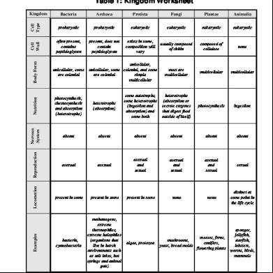
Appendix A 65665d
November 2019 51
Appendix A Final Draft 545h26
November 2022 0
Appendix 4g1e1q
September 2020 0
Appendix 4g1e1q
February 2023 0