Assignment Shaft Design o172c
This document was ed by and they confirmed that they have the permission to share it. If you are author or own the copyright of this book, please report to us by using this report form. Report 3b7i
Overview 3e4r5l
& View Assignment Shaft Design as PDF for free.
More details w3441
- Words: 905
- Pages: 4
Assignment Shaft Design Due date/ time: Wednesday,
2nd April, 2014 at the Start of the Class (first lecture)
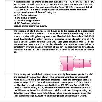
A shaft is loaded in bending and torsion such that Ma = 70 N · m, Ta = 45 N · m, Mm = 55 N · m, and Tm = 35 N · m. For the shaft, Su = 700 MPa and Sy = 560 MPa, and a fully corrected endurance limit of Se = 210 MPa is assumed. Let Kf = 2.2 and Kf s = 1.8. With a design factor of 2.0 determine the minimum acceptable diameter of the shaft using the (a) DE-Gerber criterion. (b) DE-elliptic criterion. (c) DE-Soderberg criterion. (d) DE-Goodman criterion. Discuss and compare the results. The section of shaft shown in the figure is to be designed to approximate relative sizes of d = 0.75D and r = D/20 with diameter d conforming to that of standard metric rolling-bearing bore sizes. The shaft is to be made of SAE 2340 steel, heat-treated to obtain minimum strengths in the shoulder area of 175 kpsi ultimate tensile strength and 160 kpsi yield strength with a Brinell hardness not less than 370. At the shoulder the shaft is subjected to a completely reversed bending moment of 600 lbf · in, accompanied by a steady torsion of 400 lbf · in. Use a design factor of 2.5 and size the shaft for an infinite life.
The rotating solid steel shaft is simply ed by bearings at points B and C and is driven by a gear (not shown) which meshes with the spur gear at D, which has a 150-mm pitch diameter. The force F from the drive gear acts at a pressure angle of 20°. The shaft transmits a torque to point A of TA = 340 N · m. The shaft is machined from steel with Sy = 420 MPa and Sut = 560 MPa. Using a factor of safety of 2.5, determine the minimum allowable diameter of the 250-mm section of the shaft based on (a) a static yield analysis using the distortion energy theory and (b) a fatigue-failure analysis. Assume sharp fillet radii at the bearing shoulders for estimating stress-concentration factors.
A geared industrial roll shown in the figure is driven at 300 rev/min by a force F acting on a 3-in-diameter pitch circle as shown. The roll exerts a normal force of 30 lbf/in of roll length on the material being pulled through. The material es under the roll. The coefficient of friction is 0.40. Develop the moment and shear diagrams for the shaft modeling the roll force as (a) a concentrated force at the center of the roll, and (b) a uniformly distributed force along the roll. These diagrams will appear on two orthogonal planes.
In the double-reduction gear train shown, shaft a is driven by a motor attached by a flexible coupling attached to the overhang. The motor provides a torque of 2500 lbf · in at a speed of 1200 rpm. The gears have 20° pressure angles, with diameters shown on the figure. Use an AISI 1020 cold-drawn steel. Design one of the shafts (as specified by the instructor) with a design factor of 1.5 by performing the following tasks. (a) Sketch a general shaft layout, including means to locate the gears and bearings, and to transmit the torque. (b) Perform a force analysis to find the bearing reaction forces, and generate shear and bending moment diagrams. (c) Determine potential critical locations for stress design. (d) Determine critical diameters of the shaft based on fatigue and static
stresses at the critical locations. (e) Make any other dimensional decisions necessary to specify all diameters and axial dimensions. Sketch the shaft to scale, showing all proposed dimensions. ( f ) Check the deflection at the gear, and the slopes at the gear and the bearings for satisfaction of the recommended limits in Table 7–2. (g) If any of the deflections exceed the recommended limits, make appropriate changes to bring them all within the limits.
In the figure is a proposed shaft design to be used for the input shaft a in Prob. 7–17. A ball bearing is planned for the left bearing, and a cylindrical roller bearing for the right. (a) Determine the minimum fatigue factor of safety by evaluating at any critical locations. Use a fatigue failure criteria that is considered to be typical of the failure data, rather than one that is considered conservative. Also ensure that the shaft does not yield in the first load cycle. (b) Check the design for adequacy with respect to deformation, according to the recommendations in Table 7–2.
The shaft shown in the figure carries a 18-lbf gear on the left and a 32-lbf gear on the right. Estimate the first critical speed due to the loads, the shaft’s critical speed without the loads, and the critical speed of the combination.
A 25-mm-diameter uniform steel shaft is 600 mm long between bearings. (a) Find the lowest critical speed of the shaft. (b) If the goal is to double the critical speed, find the new diameter. (c) A half-size model of the original shaft has what critical speed? The shaft shown in the figure carries a 18-lbf gear on the left and a 32-lbf gear on the right. Estimate the first critical speed due to the loads, the shaft’s critical speed without the loads, and the critical speed of the combination.
2nd April, 2014 at the Start of the Class (first lecture)
A shaft is loaded in bending and torsion such that Ma = 70 N · m, Ta = 45 N · m, Mm = 55 N · m, and Tm = 35 N · m. For the shaft, Su = 700 MPa and Sy = 560 MPa, and a fully corrected endurance limit of Se = 210 MPa is assumed. Let Kf = 2.2 and Kf s = 1.8. With a design factor of 2.0 determine the minimum acceptable diameter of the shaft using the (a) DE-Gerber criterion. (b) DE-elliptic criterion. (c) DE-Soderberg criterion. (d) DE-Goodman criterion. Discuss and compare the results. The section of shaft shown in the figure is to be designed to approximate relative sizes of d = 0.75D and r = D/20 with diameter d conforming to that of standard metric rolling-bearing bore sizes. The shaft is to be made of SAE 2340 steel, heat-treated to obtain minimum strengths in the shoulder area of 175 kpsi ultimate tensile strength and 160 kpsi yield strength with a Brinell hardness not less than 370. At the shoulder the shaft is subjected to a completely reversed bending moment of 600 lbf · in, accompanied by a steady torsion of 400 lbf · in. Use a design factor of 2.5 and size the shaft for an infinite life.
The rotating solid steel shaft is simply ed by bearings at points B and C and is driven by a gear (not shown) which meshes with the spur gear at D, which has a 150-mm pitch diameter. The force F from the drive gear acts at a pressure angle of 20°. The shaft transmits a torque to point A of TA = 340 N · m. The shaft is machined from steel with Sy = 420 MPa and Sut = 560 MPa. Using a factor of safety of 2.5, determine the minimum allowable diameter of the 250-mm section of the shaft based on (a) a static yield analysis using the distortion energy theory and (b) a fatigue-failure analysis. Assume sharp fillet radii at the bearing shoulders for estimating stress-concentration factors.
A geared industrial roll shown in the figure is driven at 300 rev/min by a force F acting on a 3-in-diameter pitch circle as shown. The roll exerts a normal force of 30 lbf/in of roll length on the material being pulled through. The material es under the roll. The coefficient of friction is 0.40. Develop the moment and shear diagrams for the shaft modeling the roll force as (a) a concentrated force at the center of the roll, and (b) a uniformly distributed force along the roll. These diagrams will appear on two orthogonal planes.
In the double-reduction gear train shown, shaft a is driven by a motor attached by a flexible coupling attached to the overhang. The motor provides a torque of 2500 lbf · in at a speed of 1200 rpm. The gears have 20° pressure angles, with diameters shown on the figure. Use an AISI 1020 cold-drawn steel. Design one of the shafts (as specified by the instructor) with a design factor of 1.5 by performing the following tasks. (a) Sketch a general shaft layout, including means to locate the gears and bearings, and to transmit the torque. (b) Perform a force analysis to find the bearing reaction forces, and generate shear and bending moment diagrams. (c) Determine potential critical locations for stress design. (d) Determine critical diameters of the shaft based on fatigue and static
stresses at the critical locations. (e) Make any other dimensional decisions necessary to specify all diameters and axial dimensions. Sketch the shaft to scale, showing all proposed dimensions. ( f ) Check the deflection at the gear, and the slopes at the gear and the bearings for satisfaction of the recommended limits in Table 7–2. (g) If any of the deflections exceed the recommended limits, make appropriate changes to bring them all within the limits.
In the figure is a proposed shaft design to be used for the input shaft a in Prob. 7–17. A ball bearing is planned for the left bearing, and a cylindrical roller bearing for the right. (a) Determine the minimum fatigue factor of safety by evaluating at any critical locations. Use a fatigue failure criteria that is considered to be typical of the failure data, rather than one that is considered conservative. Also ensure that the shaft does not yield in the first load cycle. (b) Check the design for adequacy with respect to deformation, according to the recommendations in Table 7–2.
The shaft shown in the figure carries a 18-lbf gear on the left and a 32-lbf gear on the right. Estimate the first critical speed due to the loads, the shaft’s critical speed without the loads, and the critical speed of the combination.
A 25-mm-diameter uniform steel shaft is 600 mm long between bearings. (a) Find the lowest critical speed of the shaft. (b) If the goal is to double the critical speed, find the new diameter. (c) A half-size model of the original shaft has what critical speed? The shaft shown in the figure carries a 18-lbf gear on the left and a 32-lbf gear on the right. Estimate the first critical speed due to the loads, the shaft’s critical speed without the loads, and the critical speed of the combination.
Related Documents 3m3m1z
Assignment Shaft Design o172c
November 2019 27
Rear Axle Shaft Design 19134x
November 2019 63
Design And Calculation Shaft 3o6s4l
July 2020 0
Shaft Design Project 5u1dh
October 2019 76
Design Of Circular Shaft 4w6j2g
January 2022 0
Shaft Design Procedure 47s2f
December 2019 26More Documents from "Hasham Mehmood" 5h1zj
Assignment Shaft Design o172c
November 2019 27
Seed_oil_extraction_unit_cotton_seed.pdf 3m6p16
December 2019 57
Companies Emails 35r1b
December 2020 0
Acca P7 Revision Mock June 2012 Answers Version 4 Final At 5th May 2012 591i4
November 2019 55
Coca- Cola Internship Report 5073s
October 2019 57