Autosar Diagnostic 3s496x
This document was ed by and they confirmed that they have the permission to share it. If you are author or own the copyright of this book, please report to us by using this report form. Report 3b7i
Overview 3e4r5l
& View Autosar Diagnostic as PDF for free.
More details w3441
- Words: 2,488
- Pages: 28
AUTOSAR Diagnostic Overview
and Definitions Diagnostic service information exchange initiated by a client in order to require diagnostic information from a server and/or to modify its behavior for diagnostic purposes
Server function that is part of an electronic control unit and that provides the diagnostic services
Tester system that controls functions such as test, inspection, monitoring or diagnosis of an on-vehicle electronic control unit and which may be dedicated to a specific type of operator (e.g. a scan tool dedicated to garage mechanics or a test tool dedicated to assembly plant agents)
Diagnostic data data that is located in the memory of an electronic control unit which may be inspected and/or possibly modified by the tester (diagnostic data includes analogue inputs and outputs, digital inputs and outputs, intermediate values and various status information)
Architecture – Contents of Software Layer •
•
•
•
•
•
The Debugging module s debugging of the AUTOSAR BSW. It interfaces to ECU internal modules and to an external host system via communication . The Diagnostic Event Manager is responsible for processing and storing diagnostic events (errors) and associated FreezeFrame data. The module Diagnostic Log and Trace s logging and tracing of applications. It collects defined log messages and converts them into a standardized format. The Diagnostic Communication Manager provides a common API for diagnostic services The Function Inhibition Manager is responsible for providing a control mechanism for software components and the functionality The Network layer part of
Why DCM?
The functionality of the DCM module is used by external diagnostic tools during the development, manufacturing or service The DCM module ensures diagnostic data flow and manages the diagnostic states, especially diagnostic sessions and security states The DCM module checks if the diagnostic service request is ed and if the service may be executed in the current session according to the diagnostic states.
Overview of the communication between the external diagnostic tools and the onboard AUTOSAR Application
DCM Overview with AUTOSAR In the AUTOSAR architecture, the Diagnostic Communication Manager module is located in a ‘Communication services’ (Service Layer). The Dcm Interfaces with communication modules to transfer information from an ECU to an off-board Tester and viceversa. UDS Service This refers to a UDS Service as defined in ISO14229-1 Note: All UDS Service defined in ISO14229-1 is not ed by the Dcm module OBD Service This refers to an OBD Service as defined in ISO15031-5 Note: All UDS OBD Service as defined in ISO15031-5 is not ed by the Dcm module
Diagnostics Communication Manager The functionality of Dcm module is used by external diagnostic tools e.g. in the development, manufacturing or service Diagnostic services include functions such as test, inspection, monitoring or diagnosis of on-board vehicle servers (ECU). The information transferred might consist of ECU fault information, parameter reporting, control routines, calibration values and other types of data used in performing ECU diagnostics. The Dcm module is network independent. All the network specific functionality (the Specifics of networks like CAN, LIN, FlexRay or MOST) is handled outside of the Dcm. The PDU Router (PduR) module provides a networkindependent interface to the DCM module. The Dcm requests data or functional state from SW-Cs via port interfaces or from other BSW modules through direct function calls if any of the data elements or functional states
Unified diagnostic services (UDS) – ed (R4.0.3)
The DSP provides the following diagnostic UDS services: o o o o o o o o o o o o o o o o o o o o o o
DiagnosticSessionControl (0x10) ECUReset (0x11) SecurityAccess (0x27) CommunicationControl(0x28) TesterPresent (0x3E) ControlDTCSetting (0x85) ResponseOnEvent (0x86) LinkControl (0x87) ReadDataByIdentifier (0x22) ReemoryByAddress (0x23) ReadScalingDataByIdentifier (0x24) ReadDataByPeriodicIdentifier (0x2A) DynamicallyDefineDataIdentifier (0x2C) WriteDataByIdentifier (0x2E) ClearDiagnosticInformation (0x14) ReadDTCInformation (0x19) InputOutputControlByIdentifier (0x2F) RoutineControl (0x31) Request (0x34 hex) Request (0x35) TransferData (0x36 hex) RequestTransferExit (0x37)
OBD service ed – ed (R4.0.3)
The DSP provides the following diagnostic OBD services: o Relevant OBD Service Identifier o Request current powertrain diagnostic data ($01) o Request current powertrain freeze frame data ($02) o Request confirmed emission related DTCs ($03) o Clear/Reset emission related diagnostic information ($04) o Request monitoring test results for specific monitored systems ($06) o Request pending emission related DTCs ($07) o Request control of on-board system, test or component ($08) o Request vehicle information and IUMPR ($09) o Request emission-related DTCs with permanent status ($0A)
Diagnostics Event Manager The Diagnostic Event Manager (Dem) handles and stores the events detected by diagnostic monitors in both Software Components (SW-Cs) and Basic software (BSW) modules The stored event information is available via an interface to other BSW modules or SW-Cs The Dem module uses the EventId to manage the status of the ´Diagnostic Event´ of a system and performs the required actions for individual test results E.g. stores the freeze frame(If qualified as Failed) The Dem module shall represent each Diagnostic Event by an EventId and the related EventName. All monitors and BSW modules use the EventId as a symbolic EventName. The EventId and the related EventName shall be unique per Dem module represented by the ECU configuration
Diagnostic Log and Trace Each application software component (SW-C) can report errors to the Dlt Collects log messages and converts them into a standardized format. The Dlt forwards the data to the Dcm or a CDD which uses a serial interface for example Logging logging of errors, warnings and info messages from AUTOSAR SW-Cs, providing a standardized AUTOSAR interface gathering all log and trace messages from all AUTOSAR SW-Cs in a centralized AUTOSAR service component (Dlt) in the BSW logging of messages from Det and logging of messages from Dem Tracing RTE activities Control individual log and trace messages can be enabled/disabled and Log levels can be controlled individually by back channel Generic Dlt is available during development and production phase access over standard diagnosis or platform specific test interface is possible and
Diagnostic Log and Trace
Debugging Module To a (system integrator or BSW developer) during development, in case the basic software does not behave as expected Collects as much information as possible about the runtime behavior of the systems without halting the processor Data is transmitted to an external host system via communication, to enable the to identify the source of a problem An internal buffer is provided to decouple data collection from Main tasks of the Debugging Module are to data transmission Collect and store data for tracing purposes Collect and immediately transmit data to host Modify data in target memory on host request Transmit stored data to host Accept commands to change the behavior of the Debugging Module
Tracing Principles Debugging Module use cases Tracing means collecting information from running software. To perform tracing, the software is not halted Tracing of variables Cyclically on event Tracing of functions In order to implement tracing of functions, the code has to be instrumented with calls to Collect Function Tracing Information (function entry) API when the function is entered and calls to Collect Function Tracing Information (function exit) API before leaving the function Tracing of SW-C The debugging module offers functions to the RTE to trace information from the following RTE events signal transmission signal reception COM callback start runnable
AUTOSAR DEM Overview
DEM – Diagnostics Event Manager The service component Diagnostic Event Manager (Dem) is responsible for processing and storing diagnostic events (errors) and its associated data The Dem offers interfaces to the application layer and to other BSW modules to make the stored event information available Dem provides fault information to the Dcm
Diagnostics Event A ´Diagnostic Event´ defines the atomic unit that can be handled by the Dem module The status of a ´Diagnostic Event´ represents the result of a monitor The Dem receives the result of a monitor from SW-C via the RTE or other BSW modules The Dem module uses the EventId to manage the status of the ´Diagnostic Event´ of a system and performs the required actions for individual test results
Elements of Diagnostics Event Event priority It is defined as a ranking of events based upon level of importance It is used to determine which fault entries may be removed from the event memory in the case of the number of stored events exceeds the maximum number of memory entries A priority value of 1 is the highest priority. Larger priority value shall define lower importance Event occurrence The Dem module provides an occurrence counter per event memory entry The Dem module increments the occurrence counter by one if the related event is already stored in the event memory and the UDS DTC status bit 0 (TestFailed) changes from 0 to 1 If the configuration parameter DemOccurrenceCounterProcessing (in container DemGeneral) is DEM_PROCESS_OCCCTR_CDTC, the Dem module only increments the occurrence counter if the fault confirmation has been successfully finished
Elements of Diagnostics Event Event kind There are two different types of events: – BSW-related events (reported via C-API – Dem_ReportErrorStatus) – SW-C-related events (reported via RTE operation – SetEventStatus) Event significance There are two different significance levels of events: – “fault”: classifies a failure, which relates to the component/ECU itself (and requires for example a repair action) – “occurrence”: classifies an issue, which indicates additional information concerning insufficient system behavior (and relates for example to a condition out of the ECU’s control) Event destination The configuration parameter DemEventDestination
Diagostic monitor
Diagostic monitor A diagnostic monitor is a routine entity determining the proper functionality of a component The monitoring function identifies a specific fault type (e.g. short to ground, open load, etc.) for a monitoring path A monitoring path represents the physical system or a circuit, that is being monitored (e.g. sensor input). Each monitoring path is associated to exactly one diagnostic event. If the monitor debounces on its own, the reporting API is called only after a qualified result (ed or failed) is available If the monitor uses Dem-internal debouncing mechanism, the reporting API is called whenever the code with the functional check is executed
DTC & DTC groups Diagnostic trouble code There are two different kinds of DTCs: – non OBD-relevant DTCs (UDS DTCs) – OBD-relevant DTCs DTC groups The following DTC groups are provided: • emission-related DTC group (optional, fixed value = 0x000000) • powertrain DTC group (optional, configurable value) • chassis DTC group (optional, configurable value) • body DTC group (optional, configurable value) • network communication DTC group (optional, configurable value) • further -defined DTC groups (optional, configurable value) • ‘all DTCs’ DTC group (mandatory, fixed value = 0xFFFFFF)
Operation cycle management The Dem module uses different operation cycles The cycles could either be provided by other BSW modules and SW-C or generated by the Dem module itself Examples of operation cycles are: • - driving cycle • - engine warm up cycle • - ignition on/off cycle • - power up/power down cycle • - operation active/ive cycle - accumulated operating time The operation cycle management of the Dem module uses the reported state (DEM_CYCLE_STATE_START / DEM_CYCLE_STATE_END) of the API Dem_SetOperationCycleState (refer to chapter 8.3.3.6) to set the Dem specific operation cycle state (started / ended)
Event status management The ´Event Status Management´ is the Dem’s ability to record and retain events, event status and associated data The Dem module provides the capability to report the status of an event through the API Dem_SetEventStatus allowing a diagnostic monitor to inform the Dem about the result of the internal diagnostic test The Dem module provides the capability to reset the failed status of an event without reporting a ed result through the API Dem_ResetEventStatus The Dem module provides the capability to retrieve the current UDS DTC status byte of a specific event through the API Dem_GetEventStatus The Dem module provides the current event failed status through the API Dem_GetEventFailed The Dem module provides the current event tested status through the API Dem_GetEventTested
Status bit update In case a qualified diagnostic event (ed / failed) is reported to the Dem module, the Dem performs the event status transition immediately for the bits being relevant for fault reactions • Bit 0 TestFailed • Bit 1 TestFailedThisOperationCycle • Bit 4 TestNotCompletedSinceLastClear • Bit 5 TestFailedSinceLastClear • Bit 6 TestNotCompletedThisOperationCycle Notification of status bit changes The Dem module triggers the event-specific callback-function EvenStatusChanged on each event status change The configuration container DemCallbackEventStatusChanged is used to specify one or more ports/c-callbacks per event
Debouncing of diagnostic events If the Dem module is configured to implement the debounce algorithm for a specific event, one of the following debounce algorithms are to be performed Dem-internally Counter based debounce algorithm Time based debounce algorithm Further specific debounce algorithms Monitor internal debounce algorithm The Dem module s the event-specific configuration of debounce algorithms by using the configuration container DemDebounceAlgorithmClass
Counter based debounce algorithm The Dem module calculates the fault detection counter (-128 …+127 according to UDS) based on the value and range of the internal debounce counter to map the internal counter values linearly to the external values DemDebounceCounterFailedThreshold defines the event-specific limit indicating the failed status (active) DemDebounceCounteredThreshold defines the event-specific limit indicating the ed status (ive) The Dem module increments the internal debounce counter with its configured step-size (DemDebounceCounterIncrementStepSize), when the monitor reports DEM_EVENT_STATUS_PREFAILED The Dem module decrements the internal debounce counter with its configured step-size (DemDebounceCounterDecrementStepSize), when the monitor reports DEM_EVENT_STATUS_PREED If the monitor reports DEM_EVENT_STATUS_FAILED, the Dem module sets the internal debounce counter value to its configured threshold being the failed criteria If the monitor reports DEM_EVENT_STATUS_ED, the Dem module sets the internal debounce counter value to its configured threshold being the ed criteria
Counter based debounce algorithm contd.
The Dem module provides the configuration parameter DemDebounceCounterJumpDown for activating or deactivating the jump down behavior If the jump down behavior is active, the Dem module provides the configuration parameter DemDebounceCounterJumpDownValue defining the new internal debounce counter init value if the counting direction changes from incrementing to decrementing The Dem module provides the configuration parameter DemDebounceCounterJumpUp for activating or deactivating the jump up behavior If the jump up behavior is active, the Dem module provides the configuration parameter DemDebounceCounterJumpUpValue defining the new internal debounce counter init value if the counting direction changes from decrementing to incrementing
Counter based debounce algorithm Example
Related Documents 3m3m1z
Autosar Diagnostic 3s496x
July 2021 0
Autosar Wiki 1q1932
November 2019 56
Autosar Methodology 1u1345
December 2019 48
Embedded Coder Autosar h6461
December 2021 0
Targetlink Autosar Guidelines 4ji5l
December 2019 51
Autosar Sws Adcdriver 2596
November 2022 0More Documents from "Santosh" 73611f
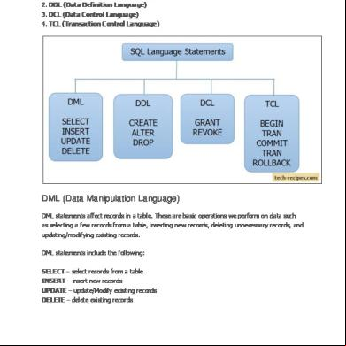
The Four Main Categories Of Sql Statements Are As Follows 6p213y
November 2019 79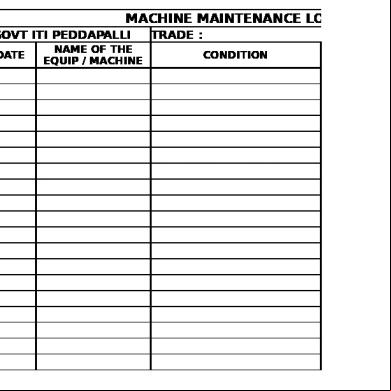
Machine Maintenance Log Book z252d
December 2019 296
Autosar Diagnostic 3s496x
July 2021 0
39677614 Power Builder Training 704n8
June 2022 0
Arcsight Esm Image Viewer Tutorial 595j24
April 2021 0