Arcsight Esm Image Viewer Tutorial 595j24
This document was ed by and they confirmed that they have the permission to share it. If you are author or own the copyright of this book, please report to us by using this report form. Report 3b7i
Overview 3e4r5l
& View Arcsight Esm Image Viewer Tutorial as PDF for free.
More details w3441
- Words: 1,336
- Pages: 18
Using Visio 2003 to Create ESM Image Viewer Gary Freeman ArcSight Geek Canada
Agenda Visio For Power s Reference Material Tutorial #1: Creating a Visio Image for ESM Tutorial #2: Using ESM Image Editor
Visio For Power s
Most Used Short-Cuts Ctrl-S: Save! Ctrl-D: Cloning Ctrl-1: Pointer Tool Ctrl-2: Text Tool Ctrl-Shift-F: Bring To Front Ctrl-Shift-B: Send To Back
Reference Material
Visio 2003 Quick Guide PDF Stencils / Templates www.visiocafe.com Visio Guy www.visguy.com MS Visio Help Online http://office.microsoft.com/enus/visio/FX100649221033.aspx?CTT=96&Origin=CL10063631103 3 Visio 2007 Viewer http://www.microsoft.com/s/details.aspx?FamilyId=D88 E4542-B174-4198-AE31-6884E9EDD524&displaylang=en Visio 2003 / 2007 Feature Comparison http://office.microsoft.com/en-us/visio/fx101759431033.aspx VSDfx 3D Isometric Shapes http://www.visiocafe.com/s/vsdfx/VSDfx-3D.zip Tutorial #1 finished drawing
Reference Material: Visio Shortcuts
Tutorial #1: Creating a Visio Image for ESM
Scope: Create image from scratch for logical Device Category monitor and import into ESM Image Editor Tools: Visio 2003 Difficulty: Moderate Skills Learned: Shortcuts
Tutorial #1: Creating a Visio Image for ESM 1.
2.
3.
Create a new drawing with landscape orientation and metric units Create a rectangle 254 mm x 130 mm (approx) and select “Shapes > Center Drawing” and “Shapes > Align” and center horizontally / vertically and choose “Create guide and glue shapes to it” Select the shape and select the “Fill Color” tool and select Gray50%
Tutorial #1: Creating a Visio Image for ESM 4.
5.
6.
7.
Create a smaller 242 mm wide x 10 mm high rectangle shape on the grid above the existing rectangle Right-mouse click and select “Format > Fill” and select the Pattern drop-down and select “30:” (ramp up) and Pattern Color “16:” and click Ok Double click on the new box and type “Device Categories” and change the font size to 14 Move the box down so it becomes the header for the larger rectangle.
Tutorial #1: Creating a Visio Image for ESM 8. 9.
10.
11.
12.
13.
Select heading object and press Ctrl-D to duplicate it Resize the new cloned object to 115mm x 48mm and place in upper left quadrant of the drawing Now select the object and right-mouse click and select “Format > Text” and then change the “Text Block” alignment to “Top” and click Ok. Double-click on the new object and change the text to “Security Devices” Duplicate the new object three more times and change the text to “Network Devices”, “Operating Systems” and “Applications” Create additional guides to align the shapes and the spacing between the shapes
Tutorial #1: Creating a Visio Image for ESM 14.
15.
16.
17.
18.
19.
Add additional boxes inside each of the device quadrants and add ramped fills (lighter gray than outside box with ramp in opposite direction). Use either the default Visio stencils or the VSDfx stencils (link above) to add icons relative to the device categories. Select all of objects (CtrlA) and then group them (Ctrl-Shift-G) and save the drawing. Finally, export the drawing as a JPG by selecting “Save As” and clicking the drop-down for “Save as type” and select “JPG File Interchange Format (JPG)”, click Save. In the save dialog adjust “Quality” to 100% and select “Resolution > Custom” and change from 96x96 pixels to 110x110. Click Ok.
Tutorial #2: Using ESM Image Editor
Overview Enable Image Editor in console by editing .ast file Start Image Editor and Import image Associate chart objects with filters Save and run Image Viewer What’s not covered: Creation of the filters used by the image viewer
Tutorial #2: Using ESM Image Editor 1. 2.
Close any instance of the ArcSight Console. Locate the file ARCSIGHT_HOME\Console\Current \.ast (or whatever name is being used to access ESM) where the ArcSight Console is installed and open the file in a text editor and add the following line (and then save):
console.ui.imageEditor=true 3.
4.
Start the console and with the “” and click on the Views file menu option and select Image Editor. You will now have access to the image editor with an empty palette. Click on the “Magnetic Grid” icon and select “Activated and Visible”, change grid spacing to “10” and select ‘Display Lines” and click Ok (the dialog will not go away and you’ll have to close it manually).
Tutorial #2: Using ESM Image Editor 4.
Within the Image Editor, select the New Image Entry icon on the top of the left-hand tool list and click anywhere on the palette to bring up the open file dialog and select the image you saved in the first tutorial.
Tutorial #2: Using ESM Image Editor 5.
6.
7.
Next, click the vertical bar chart object on the toolbar and click the area within the “Security Devices” quadrant. A dialogue will be displayed requiring input. Enter the following details: Node Name: SecurityDevices Node Label: SecurityDevices Assoc. Filter: (I created one that uses Express Firewall, VPN and AV filters) Drill Down: Grid Table Viewer Name: SecurityDevices Viewer Params: (auto-populated) Click Ok. Once saved the chart object will have to be adjusted manually using the anchors to be centered and sized correctly within the drawing quadrant. Use the magnetic grid to assist in placing.
Tutorial #2: Using ESM Image Editor 8.
9.
Once you have created the first object, select the chart and click on the Copy and then the Paste toolbar icons. A copy will be pasted that will have reverted to the default chart size. Use the first chart object you have formatted as a reference and manually resize the pasted object (the Image Editor does not have any guides or sizing tools apart from selecting the anchors). Once you have copied and pasted the remaining three chart objects, right click on each and select Copy Paste “Properties” and rename all of the Nodes Names, Node Labels and Viewer Names with the names of each device type. Select the correct filters for each type. When you are done the properties for each chart object will be:
Tutorial #2: Using ESM Image Editor 10.
11.
Now the Image Viewer is complete. Save it by clicking the Save icon on the toolbar and when prompted name the ArcSight Image Viewer “DeviceMonitor” and select “Default Viewer” and “Ok”. Next, start the Replay Agent and start sending demo events to ESM. Open the “Live” channel and select the “Select Channel Viewer Type: icon on the bottom right corner of the channel window and select “Image Viewer > DeviceMonitor” to display the new image.
Tutorial #2: Finished Product
Disclaimer: The content provided in this instructional presentation is not ed as official ArcSight training material and is not ed by ArcSight. Moreover, the content is intended to familiarize the audience with advanced features that are usually performed by ArcSight Professional Services. If the content you have created as a result of this tutorial does not work or causes unexpected results ArcSight is in no way liable as this instructional content was provided as is and is not official ArcSight ratified content.
Caveats: While the ArcSight ESM Image Viewer is aesthetically pleasing as a custom dashboard, special consideration must be used in planning the number of chart objects and filters used in the creation of this project since the 4.x version of ArcSight ESM uses a separate Active Channel to populate the chart objects. As an example, if you have a global map depicting chart objects for 15 different countries, you are essentially opening 15 consecutive Active Channels to populate the objects on the map.
Finally: Gary Freeman is the sole creator of this content and does not represent ArcSight with this content nor does this content reflect the views or best practices of ArcSight, Inc. Should you have any questions or concerns please [email protected]. However, please note, this content is provided “as is” and I can not guarantee the effectiveness of the material nor be held able for any mishaps resulting in damages, service interruptions, outages or any other synonym for “unexpected loss of service”.
www.arcsight.com
© 2009 ArcSight Confidential
18
Related Documents 3m3m1z
Arcsight Esm Image Viewer Tutorial 595j24
April 2021 0
Arcsight Apis Sdk Service-oriented Architecture Esm 5i3a5k
December 2019 25
Exif.regex.info-jeffreys Image Metadata Viewer t1438
November 2019 91
Tutorial Pepakura Viewer 3g1u2p
February 2021 0
Oasis Montaj Viewer Tutorial 4c376l
April 2020 25
Tutorial Canon Image Gateway 6w1n1p
August 2021 0More Documents from "santosh" 3h241
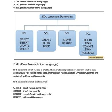
The Four Main Categories Of Sql Statements Are As Follows 6p213y
November 2019 79
Machine Maintenance Log Book z252d
December 2019 296
Autosar Diagnostic 3s496x
July 2021 0
39677614 Power Builder Training 704n8
June 2022 0
Arcsight Esm Image Viewer Tutorial 595j24
April 2021 0