Dma Controller 8257 73405l
This document was ed by and they confirmed that they have the permission to share it. If you are author or own the copyright of this book, please report to us by using this report form. Report 3b7i
Overview 3e4r5l
& View Dma Controller 8257 as PDF for free.
More details w3441
- Words: 813
- Pages: 14
DMA CONTROLLER 8257 SUBMITTED BY :KOPAL AGRWAL
It is a device to transfer the data directly between IO device and memory without through the U. So it performs a high-speed data transfer between memory and I/O device.
The features of 8257 is, •The 8257 has four channels and so it can be used to provide DMA to four I/O devices •Each channel can be independently programmable to transfer up to 64kb of data by DMA. •Each channel can be independently perform read transfer, write transfer and transfer.
It is a 40 pin IC The functional blocks of 8257 are data bus buffer, read/write logic, control logic, priority resolver and four numbers of DMA channels.
PIN DIAGRAM OF 8257 DMA CONTROLLER
FUNCTIONAL BLOCK DIAGRAM OF 8257
INTERNAL ARCHITECTURE OF 8257
Operating modes of 8257 •Each channel of 8257 Block diagram has two programmable 16-bit s named as address and count . •Address is used to store the starting address of memory location for DMA data transfer. •The address in the address is automatically incremented after every read/write/ transfer. •The count is used to count the number of byte or word transferred by DMA. The format of count is,
•14-bits B0-B13 is used to count value and a 2-bits is used for •indicate the type of DMA transfer (Read/Write/Veri1 transfer). • In read transfer the data is transferred from memory to I/O device. •In write transfer the data is transferred from I/O device to memory. •Verification operations generate the DMA addresses without • generating the DMA memory and I/O control signals. •The 8257 has two eight bit s called mode set and •status . The format of mode set is,
The use of mode set is, 1. Enable/disable a channel. 2. Fixed/rotating priority 3. Stop DMA on terminal count. 4.Extended/normal write time. 5. Auto reloading of channel-2. •The bits B0, B1, B2, and B3 of mode set are used to enable/disable channel -0, 1, 2 and 3 respectively. A one in these Position will enable a particular channel and a zero will disable it. •If the bit B4 is set to one, then the channels will have rotating priority and if it zero then the channels wilt have fixed priority. 1.In rotating priority after servicing a channel its priority is made as lowest. 2. In fixed priority the channel-0 has highest priority and channel-2 has lowest priority. If the bit B5 is set to one, then the timing of low write signals (MEMW and IOW) will be extended.
•If the bit B6 is set to one then the DMA operation is stopped at the terminal count. • The bit B7 is used to select the auto load feature for DMA channel-2. •When bit B7 is set to one, then the content of channel-3 count and address s are loaded in channel-2 count and address s respectively whenever the channel-2 reaches terminal count. When this mode is activated the number of channels available for DMA reduces from four to three. • The format of status of 8257 is shown in fig.
The bit B0, B1, B2, and B3 of status indicates the terminal count status of channel-0, 1,2 and 3 respectively. A one in these bit positions indicates that the particular channel has reached terminal count. •These status bits are cleared after a read operation by microprocessor. •The bit B4 of status is called update flag and a one in this bit position indicates that the channel-2 has been reloaded from channel-3 s in the auto load mode of operation. •The internal addresses of the s of 8257 are listed in table.
INTERFACING OF DMA 8257 WITH 8085 A simple schematic for interfacing the 8257 with 8085 processor is shown.
The 8257 can be either memory mapped or I/O mapped in the system. •In the scheatic shown in figure is I/O mapped in the • system. •Using a 3-to-8 decoder generates the chip select signals • for I/O mapped devices. •The address lines A4, A5 and A6 are decoded to generate • eight chip select signals (IOCS-0 to IOCS-7) and in this •the chip select signal IOCS-6 is used to select 8257. •The address line A7 and the control signal IO/M (low) are • used as enable for decoder. •The output clock of 8085 processor should be inverted and supplied to 8257 clock input for proper operation. The HRQ output of 8257 is connected to HOLD input of 8085 in order to make a HOLD request to the processor. The HLDA output of 8085 is connected to HLDA input of 8257, in order to receive the acknowledge signal from the processor once the HOLD request is accepted
•The RESET OUT of 8085 processor is connected to RESET of 8257. •The I/O addresses of the internal s of 8257 are listed in table.
Related Documents 3m3m1z

Dma Controller 8257 73405l
August 2021 0
Dma Controller 8257 73405l
December 2019 41
Programmable+dma+controller+8257 522g2k
November 2019 31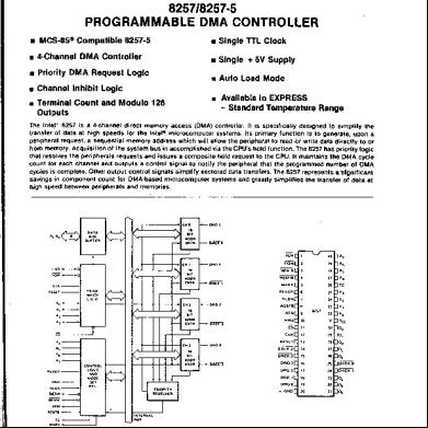
Intel 8257 Programmable Dma Controller 73151o
November 2019 46
Dma 8257 1hx3w
August 2021 0
1521348160000_8237 Dma Controller 1z4r73
December 2019 29More Documents from "Sreekanth Pagadapalli" 2h2q5v
Dma Controller 8257 73405l
August 2021 0
8096 5c5g
November 2021 0
6l6m1j
December 2019 67
Sudarshana Maha Mantra.pdf 2p4q6d
October 2019 375
How To Share Internet From A Pc Via A Usb Cable To An Android Phone - Quora 3k4x2e
November 2019 68