Flo Control 4j1l8
This document was ed by and they confirmed that they have the permission to share it. If you are author or own the copyright of this book, please report to us by using this report form. Report 3b7i
Overview 3e4r5l
& View Flo Control as PDF for free.
More details w3441
- Words: 10,576
- Pages: 24
Check Valves Transition, Compression & Repair Fittings April 2010
R
Over 20 years ago, NDS began producing plastic drainage and landscape products. From the beginning, our commitment to leading the industry has been unwavering, leading to remarkable innovations and state-of-the-art products that fit every environment, every schedule, every need. Today, our commitment to providing one-source solutions has led to the development of superior quality drainage products, landscape products, fittings, valve and meter boxes, and drip and micro irrigation products. No product is added to our line without meeting exhaustive testing and extensive research requirements. Plus, NDS is uniquely able to offer our complete inventory of products from regional warehouses in the US. Our goal: one-business-day delivery. Our track record: outstanding. Take a moment to look through this catalog, noting the depth of our product offering. If you have any questions or to place an order, just call 1-800-726-1994 from 5 a.m. to 5 p.m. PST. and let us offer the best solution for you.
TABLE OF CONTENTS
COMPRESSION FITTINGS EXPANSION REPAIR COUPLINGS FLO-LOCK™ TRANSITION FITTINGS SCREENS TO MAKE FOOT VALVES
2-3 4 4-6 7
SPRING CHECK VALVES
7-10
SWING CHECK VALVES
10-12
CHECKMATE / SUMP PUMP CHECK VALVES
12
POOL VALVES
12
BALL VALVES
13
UNIONS
14
FIRE HYDRANT CAP
14
FLO-TAP™ & CLAMP IT™ SADDLES
14-16
TECHNICAL DATA & INSTALLATION GUIDE
17-20
MARKETING MATERIALS
21
FLOW VELOCITY CHART
22
WARRANTY AND
Back Cover 1
For customer service, please send your fax to: 1-800-726-1998 or call 1-800-726-1994.
COMPRESSION FITTINGS IPS COUPLINGS, TEES & ADAPTERS – SERIES 100
Couplings — PVC
Couplings — VC
Threaded Tee
Slip Tee
Reducing Tee w/ Threaded Outlet
PVC Male Adapter
2
Rated @ 200 PSI Static Pressure @ 72˚F
Part No.
IPS Size UC Connection
Body Length
Color
Pkg. Qty.
Case (lbs.)
Product Class
110-05 110-07 110-10 110-12 110-15 110-20 110-25 110-30 110-40 110-60
⁄2” ⁄4” 1” 11⁄4” 11⁄2” 2” 21⁄2” 3” 4” 6”
4” 41⁄4” 41⁄2” 5” 51⁄2” 6” 8” 9” 10” 10”
White White White White White White White White White White
28 24 15 10 16 12 3 3 3 1
8.5 9.0 7.5 7.5 15.5 15.5 6.0 9.9 13.5 7.0
41CF 41CF 41CF 41CF 41CF 41CF 41CF 41CF 41CF 41CF
PVC NSF/ANSI 61, ANNEX G UPC
310-05 310-07
1
⁄2” ⁄4”
4” 41⁄4”
Tan Tan
28 24
9.0 10.5
41CF 41CF
VC
Part No.
IPS Size UC Connection
IPS Branch
Body Size
Color
Pkg. Qty.
Case (lbs.)
Product Class
120-05 120-07 120-10 120-12 120-15 120-20
⁄2” ⁄4” 1” 11⁄4” 11⁄2” 2”
⁄2” FPT ⁄4” FPT 1” FPT 11⁄4” FPT 11⁄2” FPT 2” FPT
4” 41⁄4” 41⁄2” 5” 51⁄2” 6”
White White White White White White
24 20 15 15 12 10
7.5 9.0 9.0 13.5 13.5 14.5
41CF 41CF 41CF 41CF 41CF 41CF
PVC NSF/ANSI 61, ANNEX G
121-05 121-07 121-10 121-12 121-15 121-20
⁄2” ⁄4” 1” 11⁄4” 11⁄2” 2”
⁄2” S ⁄4” S 1” S 11⁄4” S 11⁄2” S 2” S
4” 41⁄4” 41⁄2” 5” 51⁄2” 6”
White White White White White White
24 20 15 15 12 10
7.5 8.5 8.5 12.5 12.5 14.0
41CF 41CF 41CF 41CF 41CF 41CF
PVC NSF/ANSI 61, ANNEX G UPC
122-75 122-15
3
⁄4” 11⁄2”
1
⁄2” FPT ⁄4” FPT
41⁄4” 51⁄2”
White White
20 12
8.0 12.5
41CF 41CF
PVC NSF/ANSI 61, ANNEX G
Part No.
IPS Size UC Connection
IPS Size MPT Connection
Color
Pkg. Qty.
Case (lbs.)
Product Class
Specifications
130-05 130-07 130-10 130-12 130-15 130-20
⁄2” ⁄4” 1” 11⁄4” 11⁄2” 2”
⁄2” MPT ⁄4” MPT 1” MPT 11⁄4” MPT 11⁄2” MPT 2” MPT
White White White White White White
25 20 30 20 16 12
4.0 4.0 9.0 8.0 8.0 8.5
41CF 41CF 41CF 41CF 41CF 41CF
1 3
3
1 3
1 3
1 3
1 3
1 3
3
1 3
Specifications
Specifications
PVC NSF/ANSI 61, ANNEX G UPC
Note: All dimensions are nominal. All weights are for shipping purposes only. Price (U.S. Dollars) and availability are subject to change. For customer service, please send your fax to: 1-800-726-1998 or call 1-800-726-1994.
COMPRESSION FITTINGS CTS COUPLINGS, TEES & ADAPTERS – SERIES 200
Rated @ 200 PSI Static Pressure @ 72˚F
Part No.
CTS size
Body Length
Color
Pkg. Qty.
210-05 210-07 210-10 210-12 210-15 210-20
⁄2 ” UC ⁄4” UC 1” UC 11⁄4 ” UC 1 1⁄2 ” UC 2” UC
4” 4” 41⁄4 ” 4 1⁄ 2 ” 5” 6”
White White White White White White
25 28 24 15 10 12
4.0 8.0 9.5 8.0 8.0 14.0
41CF 41CF 41CF 41CF 41CF 41CF
PVC NSF/ANSI 61, ANNEX G UPC
410-05 410-07 410-10
⁄2 ” UC ⁄4” UC 1” UC
4” 4” 4 1⁄ 2 ”
Tan Tan Tan
25 28 24
4.4 8.0 10.0
41CF 41CF 41CF
VC
3
Part No.
CTS Size
IPS Branch
Body Length
Color
Pkg. Qty.
Case (lbs.)
Product Class
⁄2 ” UC ⁄4 ” UC 1” UC 1 1⁄4 ” UC 1 1⁄2 ” UC 2” UC
⁄2 ” FPT ⁄4 ” FPT 1” FPT 1 1 ⁄4 ” FPT 1 1⁄2 ” FPT 2” FPT
4” 4” 41⁄4” 4 1⁄ 2 ” 5” 6”
White White White White White White
36 24 18 12 15 10
7.5 7.5 9.0 8.5 14.5 14.0
41CF 41CF 41CF 41CF 41CF 41CF
PVC NSF/ANSI 61, ANNEX G
⁄2 ” UC ⁄4 ” UC
2 1⁄2 ” FPT 2 3⁄4 ” FPT
4” 4”
Tan Tan
36 24
8.0 8.8
41CF 41CF
VC
CTS Size
Color
Pkg. Qty.
Case (lbs.)
Product Class
⁄2” S x 3⁄8” Tube
White
50
Part No.
For Use with IPS Compression Size
Color
Pkg. Qty.
Aluminum Wrenches
W00-25 W00-30 W00-40 W00-60
2 ⁄2 ” 3” 4” 6”
Strap Wrenches (adjustable)
BOA-104 BOA-106
1
PVC Couplings
VC Couplings
PVC Threaded Tee
VC Threaded Tee
3
1
220-05 220-07 220-10 220-12 220-15 220-20
1
420-05 420-07
1
Part No. PVC Spigot Adapter
1
1137-35
3
3
1 3
1
Case (lbs.)
10.0
Product Class
41FL
Specifications
Specifications
Specifications Adapter converts 1⁄2” CTS valves to accept 3⁄8” supply tube. Not rated.
WRENCHES
1
⁄2 ” - 4” ⁄2 ” - 6”
1
Aluminum Aluminum Aluminum Aluminum
Case (lbs.)
Product Class
Specifications
1 1 1 1
41CF 41CF 41CF 41CF
Aluminum
Bulk Bulk
41CF 41CF
Plastic Handle Rubber Strap
Note: All dimensions are nominal. All weights are for shipping purposes only. Price (U.S. Dollars) and availability are subject to change. For customer service, please send your fax to: 1-800-726-1998 or call 1-800-726-1994.
3
EXPANSION REPAIR COUPLINGS
Pro-Span™ — Non Union
Flo-Span™ — With Union
Rated @ 200 PSI Static Pressure @ 72˚F
Part No.
IPS Size (SxSpg)
Body Length
Color
Pkg. Qty.
118-05 118-07 118-10 118-12 118-15 118-20 118-25 118-30 118-40
⁄2” ⁄4” 1” 11⁄4” 11⁄2” 2” 21⁄2” 3” 4”
51⁄2” 53⁄4” 67⁄8” 77⁄8” 91⁄2” 97⁄8” 133⁄8” 151⁄4” 163⁄4”
White White White White White White White White White
28 24 15 10 16 12 3 3 3
6.5 8.0 8.8 8.0 19.0 18.5 10.0 13.0 20.5
41XC 41XC 41XC 41XC 41XC 41XC 41XC 41XC 41XC
PVC 118-05 Thru 25: NSF/ANSI 14 UPC
117-05 117-07 117-10 117-12 117-15 117-20
⁄2” ⁄4” 1” 11⁄4” 11⁄2” 2”
53⁄4” 6 3⁄4” 7 3⁄4” 9” 10” 101⁄2”
White White White White White White
28 24 15 10 16 12
9.0 10.7 12.0 11.0 21.8 21.5
41XC 41XC 41XC 41XC 41XC 41XC
PVC
1 3
1 3
Case (lbs.)
Product Class
Specifications
FLO-LOCK™ TUBE SIZE SIDR-7 COUPLINGS & ADAPTERS – SERIES 800 Part No.
810-07 810-10 * 810-12
Coupling
Tube Size
Connection Size
Length (inches)
Color
Pkg. Qty.
Case (lbs.)
Product Class
⁄4” 1” 11⁄4”
3
⁄4” x 3⁄4” TS 1” x 1” TS 11⁄4” x 11⁄4” TS
41⁄ 2 ” 41⁄ 2 ” 5”
White White White
24 15 10
9.5 8.2 7.7
41FL 41FL 41FL
For use on Polyethylene Tube size SIDR-7 160 & 200 PSI ASTM D-2239 PVC NSF/ANSI 61, ANNEX G UPC
3
*Inset stifffener supplied–must be used with this fitting
Specifications
Male Adapter
830-07 830-10 830-12 830-71 830-121
3 ⁄4” 1” 11⁄4” 3 ⁄4” x1” 1”x11⁄4”
3 ⁄4” MPT x 3⁄4” TS 1” MPT x 1” TS 11⁄4” MPT x 11⁄4” TS 3 ⁄4” MPT x 1” TS 1” MPT x 11⁄4” TS
25⁄8” 27⁄8” 31⁄2” 27⁄8” 3”
White White White White White
20 28 16 18 12
4.5 9.0 7.3 4.0 4.3
41FL 41FL 41FL 41FL 41FL
For use on Polyethylene Tube size SIDR-7 160 & 200 PSI ASTM D-2239 PVC NSF/ANSI 61, ANNEX G 830-07 thru 12: UPC
Female Adapter
831-07 831-10
3
⁄4” 1”
3 ⁄4” FPT x 3⁄4” TS 1” FPT x 1” TS
2 5⁄8” 2 7⁄8”
White White
20 28
6.0 10.0
41FL 41FL
For use on Polyethylene Tube size SIDR-7 160 & 200 PSI ASTM D-2239 PVC NSF/ANSI 61, ANNEX G
Spigot Adapter
833-07 833-71 833-10
⁄4” ⁄4” 1”
IPS Spg x 3⁄4” TS IPS Spg x 1” TS IPS Spg x 1” TS
3” 3” 3”
White White White
20 20 28
4.5 5.0 9.0
41FL 41FL 41FL
For use on Polyethylene Tube size SIDR-7 160 & 200 PSI ASTM D-2239 PVC NSF/ANSI 61, ANNEX G UPC
4
3 3
Note: All dimensions are nominal. All weights are for shipping purposes only. Price (U.S. Dollars) and availability are subject to change. For customer service, please send your fax to: 1-800-726-1998 or call 1-800-726-1994.
FLO-LOCK™ TUBE SIZE SDR-13.5 IPS COUPLINGS & ADAPTERS – SERIES 500 Part No.
Tube Size
Connection Size
Coupling
510-10
1”
1” TS x 1” TS
Male Adapter
530-10
1”
Spigot Adapter
533-10
1”
Length (inches)
Color
Pkg. Qty.
Case (lbs.)
Product Class Specifications
41⁄2”
White
24
9.0
41FL
For use on Polyethylene Tube size SDR-13.5 ASTM D 3035 PVC NSF/ANSI 61, ANNEX G UPC
1” MPT x 1” TS
2 7 ⁄8 ”
White
18
3.5
41FL
For use on Polyethylene Tube size SDR-13.5 ASTM D 3035 PVC NSF/ANSI 61, ANNEX G UPC
1” Spg x 1” TS
2 7 ⁄8 ”
White
18
3.5
41FL
For use on Polyethylene Tube size SDR-13.5 ASTM D 3035 PVC NSF/ANSI 61, ANNEX G UPC
TUBE SIZE SDR-9 CTS COUPLINGS & ADAPTERS – SERIES 700 Part No.
Tube Size
Connection Size
Length (inches)
Color
Pkg. Qty.
Case (lbs.)
Product Class Specifications
Coupling
3 3 710-07 ⁄4” ⁄4” x 3⁄4” TS 4” 710-10 1” 1” x 1” TS 4 1⁄ 2 ” 710-17 1” 1” SDR-9 x 3⁄4” SDR-11 4” 1 710-12 1 ⁄4 ” 1 1⁄4” x 1 1⁄4” TS 5” = 710-15 11⁄2 ” 11⁄2” x 11⁄2” TS 5” = 710-20 2” 2” x 2” TS 51⁄2 ” 710-17-9 1” 1” x 3⁄4” SDR 9 4” = Insert stiffeners supplied must be used with this fitting
White White White White White White White
35 24 36 15 16 12 36
10.0 8.8 12.0 7.0 9.5 10.0 2.0
41FL 41FL 41FL 41FL 41FL 41FL 41FL
For use on Polyethylene Tube size SDR-9 160-200 PSI ASTM D-2737 PVC NSF/ANSI 61, ANNEX G UPC
Male Adapter
3 3 730-07 ⁄4” ⁄4” MPT x 3⁄4” TS 2 5⁄8” 3 3 730-71 ⁄4” x 1” ⁄4” MPT x 1” TS 2 7⁄8” 730-10 1” 1” MPT x 1” TS 2 7⁄8” 1 730-12-10 1” x 1 ⁄4” 1” MPT x 1 1⁄4” TS 3 1⁄2” 730-12 11⁄4” 1 1⁄4” MPT x 1 1⁄4” TS 3 1⁄2” 730-15 11⁄2” 11⁄2” MPT x 11⁄2” TS 3 1⁄2” = 730-20 2” 2” MPT x 2” TS 4” = Insert stiffeners supplied must be used with this fitting
White White White White White White White
25 18 18 12 12 18 12
4.0 4.0 4.0 5.0 5.0 8.0 8.8
41FL 41FL 41FL 41FL 41FL 41FL 41FL
For use on Polyethylene Tube size SDR-9 160-200 PSI ASTM D2737 PVC UPC except 730-12-10
Female Adapter
3 3 731-07 ⁄4” ⁄4” FPT x 3⁄4” TS 2 5 ⁄8 ” 3 3 731-71 ⁄4” x 1” ⁄4” FPT x 1” TS 2 7 ⁄8 ” 731-10 1” 1” FPT x 1” TS 3 1⁄ 2 ” 731-12 11⁄4” 11⁄4” FPTx 11⁄4” TS 3 1⁄ 2 ” 731-12-10 1” x 11⁄4” 1” FPT x 11⁄4” TS 3 1⁄ 2 ” 731-15 11⁄2 ” 11⁄ 2 ” FPT x 11⁄2 ” TS 4 1⁄ 2 ” = 731-20 2” 2” FPT x 2” TS 2 7⁄8” = Insert stiffeners supplied must be used with this fitting
White White White White White White White
25 15 15 12 12 18 12
4.5 4.2 4.2 5.3 5.3 9.0 9.5
41FL 41FL 41FL 41FL 41FL 41FL 41FL
For use on Polyethylene Tube size SDR-9 160-200 PSI ASTM D2737 PVC NSF/ANSI 61, ANNEX G
Spigot Adapter
3 3 733-07 ⁄4” ⁄4” IPS Spg x 3⁄4” TS 2 7⁄8” 3 3 733-71 ⁄4” ⁄4” IPS Spg x 1” TS 2 7⁄8” 733-10 1” 1” IPS Spg x 1” TS 31⁄2” 733-12 11⁄4” 11⁄4” IPS Spg x 1 1⁄4” TS 31⁄2” 733-15 11⁄2” 11⁄ 2 ” IPS Spg x 1 1⁄2” TS 31⁄2” = 733-20 2” 2” IPS Spg x 2” TS 31⁄2” = Insert stiffeners supplied must be used with this fitting
White White White White White White
18 18 18 12 18 12
4.0 4.0 4.0 5.0 8.0 8.8
41FL 41FL 41FL 41FL 41FL 41FL
For use on Polyethylene Tube size SDR-9 160-200 PSI ASTM D2737 PVC NSF/ANSI 61, ANNEX G UPC
Note: All dimensions are nominal. All weights are for shipping purposes only. Price (U.S. Dollars) and availability are subject to change. For customer service, please send your fax to: 1-800-726-1998 or call 1-800-726-1994.
5
FLO-LOCK™ COUPLINGS & ADAPTERS – SERIES 100 Part No. PVC IPS Coupling with Flo-Lock
112-05 112-07 112-10 112-12 112-15 112-20 Part No.
IPS Size
Body Length (inches)
Color
Pkg. Qty.
⁄2” ⁄4” 1” 11⁄4” 11⁄2” 2”
4” 41⁄4” 41⁄2” 5” 51⁄2” 6”
White White White White White White
28 24 15 10 16 12
IPS Size
IPS Connection
Color
Pkg. Qty.
Case (lbs.)
Product Class
⁄2” ⁄4” 1” 11⁄4” 11⁄2” 2”
1
3
3
⁄2” MPT ⁄4” MPT 1” MPT 11⁄4” MPT 11⁄2” MPT 2” MPT
White White White White White White
25 20 30 20 16 12
4.0 4.0 9.0 8.0 8.0 8.5
41FL 41FL 41FL 41FL 41FL 41FL
For use on IPS sizes Rated 160 PSI @ 72° F NSF/ANSI 61, ANNEX G UPC
⁄2” ⁄4” 1” 11⁄4” 11⁄2” 2”
⁄2” FPT ⁄4” FPT 1” FPT 11⁄4” FPT 11⁄2” FPT 2” FPT
White White White White White White
25 20 14 18 16 10
4.5 5.0 4.5 8.5 9.0 7.5
41FL 41FL 41FL 41FL 41FL 41FL
For use on IPS sizes Rated 160 PSI @ 72° F NSF/ANSI 61, ANNEX G
1 3
PVC IPS Male Adapter with Flo-Lock
135-05 135-07 135-10 135-12 135-15 135-20
1
PVC IPS Female Adapter with Flo-Lock
136-05 136-07 136-10 136-12 136-15 136-20
1
1
3
3
ADAPTERS – SERIES 200, 400 AND 900 Part No.
Case (lbs.)
8.5 9.5 7.5 8.0 16.5 15.0
Product Class
41FL 41FL 41FL 41FL 41FL 41FL
Specifications For use on IPS sizes Rated 160 PSI @ 72° F
Specifications
Rated @ 160 PSI Static Pressure @ 72˚F
— For use on CTS sizeS
CTS Size
Connection (inches)
Color
Pkg. Qty.
Case (lbs.)
Product Class
⁄2” MPT ⁄4” MPT 1” MPT 11⁄4” MPT 11⁄2” MPT 2” MPT
White White White White White White
50 25 18 24 20 12
4.5 4.0 3.5 7.5 8.5 7.5
41FL 41FL 41FL 41FL 41FL 41FL
For use with CTS pipe Rated 160 PSI @ 72° F NSF/ANSI 61, ANNEX G UPC Except 235-20
⁄2” x 1⁄2” MPT ⁄4” x 3⁄4” MPT
Tan Tan
4.8 50 4.0 25
41FL 41FL
For use with CTS pipe Rated 160 PSI @ 72° F
Specifications
PVC CTS Male Adapter with Flo-Lock
235-05 235-07 235-10 235-12 235-15 235-20
1
⁄2” ⁄4” 1” 11⁄4” 11⁄2” 2”
1
3
3
VC CTS Male Adapter with Flo-Lock
435-05 435-07
1
⁄2” ⁄4”
1
3
3
Part No.
CTS Size
IPS Connection
Body Length
Color
935-07 935-10 935-12 935-125 935-15 935-20
⁄4” 1” 11⁄4” 11⁄4” 11⁄2” 2”
⁄4” Spg 1” Spg 11⁄4” Socket 11⁄2” Socket 11⁄2” Socket 2” Socket
2 ⁄8” 2 7⁄8” 3 5⁄16” 3 5⁄16” 4” 5”
White White White White White White
PVC CTS Female Adapter with Flo-Lock
Rated @ 160 PSI Static Pressure @ 72˚F
— For use on IPS sizeS
3
3
7
Pkg. Qty.
Case (lbs.)
Product Class
20 20 25 20 20 12
4.5 4.5 8.0 8.0 11.0 8.0
41CV 41CV 41CV 41CV 41CV 41CV
Specifications
For use with CTS pipe Rated 160 PSI @ 72° F ASTM B88
As cap is tightened, pressure causes the gripper ring to bite into the pipe helping to eliminate pull out. Pressure ring to control o-ring pressure Stainless steel collar on female pipe thread fittings assures lock-proof connection to metal pipe threads
Built in stiffner Stainless steel gripper ring for “controlled grip” on tubing or pipe
6
Buna N o-ring seal
Note: All dimensions are nominal. All weights are for shipping purposes only. Price (U.S. Dollars) and availability are subject to change. For customer service, please send your fax to: 1-800-726-1998 or call 1-800-726-1994.
VALVE SCREENS TO MAKE FOOT VALVES
Foot Valve Screens
Part No.
IPS Size
Body Length
Color
1800-05 1800-07 1800-10 1800-12 1800-15 1800-20
⁄2” ⁄4” 1” 11⁄4” 11⁄2” 2”
2 ⁄2” 2 2⁄ 5” 2 4⁄ 5” 31⁄2” 3 2⁄ 5” 34⁄ 5”
Black Black Black Black Black Black
1 3
1
Pkg. Qty.
Case (lbs.)
Bulk Bulk Bulk Bulk Bulk Bulk
Product Class
41CV 41CV 41CV 41CV 41CV 41CV
Specifications Material: Polyethylene 100 mesh
SPRING CHECK VALVES SPRING CHECK VALVES– PVC – SERIES 1001, 1002, 1011, 1012 Part No. FPT x FTP EPDM Gasket
SxS EPDM Gasket
SxS Clear PVC EPDM Gasket
Case (lbs.)
Rated @ 200 PSI Static Pressure @ 72˚F
Spring Tension
IPS Size Connection
Body Length
Color
Pkg. Qty.
Product Class
⁄2” ⁄4” 1” 11⁄4” 11⁄2” 2” 21⁄2” 3”
41⁄8” 41⁄8” 5 1⁄4” 6 3⁄16” 6 3⁄16” 7” 8 5⁄8” 8 5⁄8”
White White White White White White White White
20 20 20 15 15 10 8 8
4.5 4.5 8.5 12.0 13.0 15.5 26.0 26.0
41CV 41CV 41CV 41CV 41CV 41CV 41CV 41CV
1001-05 1001-07 1001-10 1001-12 1001-15 1001-20 1001-25 1001-30
1
⁄2 lb. ⁄2 lb. 1 ⁄2 lb. 1 ⁄2 lb. 1 ⁄2 lb. 1 ⁄2 lb. 1 ⁄2 lb. 1 ⁄2 lb.
1
1
3
1002-05 1002-07 1002-10 1002-12 1002-15 1002-20 1002-25 1002-30
2 lb. 2 lb. 2 lb. 2 lb. 2 lb. 2 lb. 2 lb. 2 lb.
1
⁄2 ” ⁄4 1” 11⁄4” 11⁄2” 2” 21⁄2” 3”
41⁄8” 41⁄8” 51⁄4” 6 3⁄16” 6 3⁄16” 7” 85⁄8” 85⁄8”
White White White White White White White White
20 20 20 15 15 10 8 8
4.5 4.5 8.5 12.0 13.0 15.5 26.0 26.0
41CV 41CV 41CV 41CV 41CV 41CV 41CV 41CV
1011-05-025 1011-07-025 1011-05 1011-07 1011-10 1011-12 1011-15 1011-20 1011-25 1011-30
1
⁄4 lb. ⁄4 lb. 1 ⁄2 lb. 1 ⁄2 lb. 1 ⁄2 lb. 1 ⁄2 lb. 1 ⁄2 lb. 1 ⁄2 lb. 1 ⁄2 lb. 1 ⁄2 lb.
⁄2” ⁄4” 1 ⁄2” 3 ⁄4” 1” 1 1⁄4” 11⁄2” 2” 21⁄2” 3”
41⁄8” 41⁄8” 41⁄8” 41⁄8” 51⁄4” 6 3⁄16” 6 3⁄16” 7” 8 5⁄8” 8 5⁄8”
White White White White White White White White White White
20 20 20 20 20 15 15 10 8 8
4.0 4.5 4.0 4.5 8.5 12.0 13.5 16.0 26.0 26.0
41CV 41CV 41CV 41CV 41CV 41CV 41CV 41CV 41CV 41CV
1012-05 1012-07 1012-10 1012-12 1012-15 1012-20 1012-25 1012-30 1015-25 1015-30
2 lb. 2 lb. 2 lb. 2 lb. 2 lb. 2 lb. 2 lb. 2 lb. 5 lb. 5 lb.
⁄2” ⁄4” 1” 11⁄4” 11⁄2” 2” 21⁄2” 3” 21⁄2” 3”
41⁄8” 41⁄8” 51⁄4” 6 3⁄16” 6 3⁄16” 7” 8 5⁄8” 8 5⁄8” 8 5⁄8” 8 5⁄8”
White White White White White White White White White White
20 20 20 15 15 10 8 8 8 8
4 4.5 8.5 12.0 13.5 16.0 26.0 26.0 26.0 26.0
41CV 41CV 41CV 41CV 41CV 41CV 41CV 41CV 41CV 41CV
1011C10 1011C12 1011C15 1011C20
1
⁄2 lb. ⁄2 lb. 1 ⁄2 lb. 1 ⁄2 lb.
1” 11⁄4” 11⁄2” 2”
51⁄4” 6 3⁄16” 6 3⁄16” 7”
Clear Clear Clear Clear
20 15 15 10
8.5 12.0 13.5 16.0
41CV 41CV 41CV 41CV
1012C12 1012C15 1012C20 1012C25
2 lb. 2 lb. 2 lb. 2 lb.
11⁄4” 11⁄2” 2” 2 1⁄2”
6 3⁄16” 6 3⁄16” 7” 8 5⁄8”
Clear Clear Clear Clear
15 15 10 8
12.0 13.5 16.0 26.0
41CV 41CV 41CV 41CV
1
1
3
1 3
1 3
Specifications PVC NSF/ANSI 61, ANNEX G
PVC NSF/ANSI 61, ANNEX G
Clear PVC
Note: All dimensions are nominal. All weights are for shipping purposes only. Price (U.S. Dollars) and availability are subject to change. For customer service, please send your fax to: 1-800-726-1998 or call 1-800-726-1994.
7
SPRING CHECK VALVES Part No.
Spring Tension
– SERIES 1700, 1090, 1136
IPS Size & Connection
Color
Pkg. Qty.
6.12” 6.83” 8.345” 9.735”
White White White White
20 20 12 12
Case (lbs.)
Product Class
Specifications
9.8 14.0 19.8 22.9
41CV 41CV 41CV 41CV
Rated @ 200 PSI static pressure @ 72°F 1700-07 thru 20: NSF/ANSI 61, ANNEX G
1700-07 1700-10 1700-15 1700-20
1
⁄2 lb. ⁄2 lb. 1 ⁄2 lb. 1 ⁄2 lb.
3 ⁄4” 1” 11⁄2” 2”
1702-07 1702-10 1702-15 1702-20
2 lb. 2 lb. 2 lb. 2 lb.
3 ⁄4” S x S 1” S x S 11⁄22” S x S 2” S x S
6.12” 6.83” 8.35” 9.74”
White White White White
20 20 12 12
9.8 14.0 19.8 22.9
41CV 41CV 41CV 41CV
1700C07 1700C10 1700C15 1700C20 1700C25 1700C30 1702C15 1702C20
⁄2 lb. ⁄2 lb. 1 ⁄2 lb. 1 ⁄2 lb. 1 ⁄2 lb. 1 ⁄2 lb. 2 lb. 2 lb.
3 ⁄4” 1” 11⁄2” 2” 21⁄2” 3” 11⁄2” 2”
6.12” 6.83” 8.345” 9.735” 12.625” 12.625” 8.35” 9.74”
Clear Clear Clear Clear Clear Clear Clear Clear
20 20 12 12 6 6 12 12
9.8 14.0 19.8 22.9 33.7 33.7 19.8 22.9
41CV 41CV 41CV 41CV 41CV 41CV 41CV 41CV
Compact White PVC True Union
1790-15 1790-20
1
⁄2 lb. ⁄2 lb.
11⁄2” S x S 2” S x S
6.540” 7.350”
White White
15 10
14.0 13.0
41CV 41CV
Compact Clear PVC True Union
1790C15 1790C20 1795C20
1
⁄2 lb. ⁄2 lb. 5 lb.
11⁄2” S x S 2” S x S 2” S x S
6.540” 7.350” 7.350”
Clear Clear Clear
15 10 10
14.5 14.5 14.5
22.54 30.71 30.71
41CV 41CV 41CV
VC 90°
1901-15 1903-15 1901-20 1903-20
1 lb. 3 lb. 1 lb. 3 lb.
11⁄2” 11⁄2” 2” 2”
5” 5” 51⁄2” 51⁄2”
Tan Tan Tan Tan
12 12 12 12
9 9 14 14
42.82 42.82 42.82 42.82
41CV 41CV 41CV 41CV
White PVC True Union
Clear PVC True Union
1
1 1
1
1
SxS SxS SxS SxS
Body Length
SxS SxS SxS SxS SxS SxS SxS SxS
SxS SxS S x 21⁄2” Spg S x 21⁄2” Spg
Clear body with white nut and tailpiece Rated @ 200 PSI static pressure @ 72°F
Rated@ 200 PSI static pressure @ 72°F, Clear body with white nut and tail-piece
ED ROV ign P M I s t De Quie
In-Line Valve and By Valve
1091-20 1095-20
1 ⁄2 lb. 5 lb.
2” S x S 2” S x S
Hose Thread (EPDM Gasket)
1136-07 1136-07-05 1136-07-10
1
⁄2 lb. 5 lb. 10 lb.
3
5” 5”
⁄4” MHT x FHT 4 1⁄8” ⁄4” MHT x FHT 4 1⁄8” 3 ⁄4” MHT x FHT 4 1⁄8” 3
White White
12 12
6.9 6.9
17.31 17.31
White White White
20 20 20
4.5 4.5 4.5
41CV 41CV 41CV
41CV 41CV
41⁄8” Female Hose Thread ⁄4” Male Hose Thread
3
8
Note: All dimensions are nominal. All weights are for shipping purposes only. Price (U.S. Dollars) and availability are subject to change. For customer service, please send your fax to: 1-800-726-1998 or call 1-800-726-1994.
Non-Adjustable EPDM Seal Rated @ 200 PSI static pressure at 72°F, NSF/ANSI 61, ANNEX G Rated @ 200 PSI static pressure at 72°F, NSF/ANSI 61, ANNEX G
SPRING CHECK VALVES SPA SPRING CHECK VALVES
Versa Drain
Spa Check Valve
Clear Spa Check Valve
Part No.
Body Length
1070-15GR 1070-15BK 1070-15CL 1071GH
4” 4” 4” 2.94”
Case (lbs.)
Product Class
12 12 12 1
7.6 7.6 7.6 —
41CV 41CV 41CV 41CV
Color
Pkg. Qty.
Case (lbs.)
Product Class
Gray Black Clear Garden Hose Adpt.
IPS Size & Connection
1047-10 1047-32M 1050-10 1050-20 1055-20
⁄7 lb. ⁄7 lb. 1 ⁄4 lb. 1 ⁄4 lb. 5 lb.
1” S x 11⁄4” Spg 32mm 1” S x 11⁄4” Spg 11⁄2” S x 2” Spg 11⁄2” S x 2” Spg
3 3⁄8” 3 3⁄8” 3 3⁄8” 51⁄8” 51⁄8”
White White White White White
20 20 20 12 12
5.0 5.0 5.0 7.4 8.0
41CV 41CV 41CV 41CV 41CV
1/4 lb. for air blowers Rated@ 200 PSI static pressure @ 72°F
1050C10 1050C20 1050C20-05 1050C20-10 1050C20-12 1050C20-15 1052C20 1055C20
⁄4 lb. ⁄4 lb. 1 ⁄2 lb. 10 lb. 12 lb. 15 lb. 2 lb. 5 lb.
1” S x 11⁄4” Spg 11⁄2” S x 2” Spg 11⁄2” S x 2” Spg 11⁄2” S x 2” Spg 11⁄2” S x 2” Spg 11⁄2” S x 2” Spg 11⁄2” S x 2” Spg 11⁄2” S x 2” Spg
3 3⁄8” 51⁄8” 51⁄8” 51⁄8” 51⁄8” 51⁄8” 51⁄8” 51⁄8”
Clear Clear Clear Clear Clear Clear Clear Clear
20 12 12 12 12 12 12 12
5.0 7.4 7.4 7.4 7.4 7.4 7.5 8.0
41CV 41CV 41CV 41CV 41CV 41CV 41CV 41CV
Clear PVC, 1/4 lb. for air blowers Rated@ 200 PSI static pressure @ 72°F
11⁄2” S x 2” Spg 11⁄2” S x 2” Spg 11⁄2” S x 2” Spg 11⁄2” S x 2” Spg
4” 4” 4” 4”
Clear Clear Clear Clear
12 12 12 12
6 6 6 6
41CV 41CV 41CV 41CV
Clear PVC, 1/4 lb. for air blowers Rated@ 200 PSI static pressure @ 72°F
1
1 1
ADJUSTABLE SPRING CHECK VALVES — SERIES 1200
White PVC FPT x FPT
Factory Set at 5 lb.
White PVC SxS
Drain for portable spa
Spring Tension 1
Body Length
Specifications
Part No.
S1050C20 1⁄4 lb. S1050C20-05 1⁄2 lb. S1052C20 2 lb. S1057C20 7 lb.
Clear Compact
Pkg. Qty.
Color
Part No.
Spring Tension
IPS Size & Connection
Body Length
Color
Pkg. Qty.
⁄2” ⁄4” 1” 11⁄4” 11⁄2” 2”
1
1205-05 1205-07 1205-10 1205-12 1205-15 1205-20
2 - 5 lb. 21⁄2 -5 lb. 41⁄8 -17 lb. 4 - 50 lb. 3 1⁄2 - 50 lb. 1 3⁄4 - 14 1⁄2 lb.
4 ⁄8” 41⁄8” 51⁄4” 6 3⁄16” 6 3⁄16” 9 3⁄4”
White White White White White White
20 20 20 15 15 10
1201-05 1203-05 1205-07-20 1205V07
1 lb. 3 lb. 20 lb. 5 lb.
1
⁄2” ⁄2” 3 ⁄4” 3 ⁄4” w/ VITON
41⁄8” 41⁄8” 41⁄8” 41⁄8”
White White White White
1225-07 1225-10 1225-15 1225-20 1228-15
21⁄2 - 5 lb. 41⁄4 - 17 lb. 31⁄2 - 50 lb. 13⁄4 -141⁄2 lb. 30 lb.
3 ⁄4” 1” 11⁄2 ” 2” 11⁄2 ” w/ VITON
41⁄8” 51⁄4” 6 3⁄16” 9 3⁄4” 6 3⁄16”
White White White White White
1 3
1
Specifications
Rated @ 200 PSI Static Pressure @ 72˚F Case (lbs.)
Product Class
Specifications
4.5 4.5 8.5 12.5 13.5 14.5
41CV 41CV 41CV 41CV 41CV 41CV
Rated @ 200 PSI static pressure @ 72°F Adjusting nut 11/2 turn = 1 lb. force. 1205-05 thru 20 & 1205-07-20: NSF/ANSI 61, ANNEX G
20 20 20 20
4.5 4.5 4.5 4.5
41CV 41CV 41CV 41CV
20 20 15 10 15
4.5 8.5 13.5 17.0 12.5
41CV 41CV 41CV 41CV 41CV
Rated @ 200 PSI static pressure @ 72°F Adjusting nut 11/2 turn = 1 lb. force.
Factory Set at 5 lb.
Note: All dimensions are nominal. All weights are for shipping purposes only. Price (U.S. Dollars) and availability are subject to change. For customer service, please send your fax to: 1-800-726-1998 or call 1-800-726-1994.
9
SPRING CHECK VALVES Body Length
Color
Pkg. Qty.
Case (lbs.)
Product Class
2 - 41⁄2 lb. 1⁄2” 21⁄2 - 5 lb. 3⁄4” 41⁄4 - 17 lb. 1” 1 ⁄2” 30 lb. 1 1 lb. ⁄2”
4 1⁄8” 4 1⁄8” 51⁄4” 4 1⁄8” 4 1⁄8”
White White White White White
20 20 20 20 20
4.5 4.5 8.5 4.5 4.5
41CV 41CV 41CV 41CV 41CV
PVC Adjusting nut 11/2 turn = 1 lb. force. All 1235-xx-xx NSF/ANSI 61, ANNEX G
1750-20 1753-20
1 - 14 lb. 2” 15 - 30 lb. 2”
93⁄4” 93⁄4”
White White
10 10
19.0 19.0
41CV 41CV
PVC Adjusting nut 11/2 turn = 1 lb. force.
Vacuum Relief Valve
1171V57
1
⁄2 lb.
1
⁄2” S x 3⁄4” MPT
4 1⁄8”
Black
20
19.0
41CV
Adjusting nut 11/2 turn = 1 lb. force. Polypropylene w/cap and Viton Seals Not yet rated
Inline Adjustable
1101-05 1101-07 1101-10
2-14 lb. 2-14 lb. 2-14 lb.
1 3
⁄2” ⁄4” 1”
MPT x FPT MPT x FPT MPT x FPT
Gray Gray Gray
30 25 20
3.2 3.5 4.2
41CV 41CV 41CV
1100-05 1100-07 1100-10 1102-07
2-14 lb. 2-14 lb. 2-14 lb. 2-14 v
1
⁄2” ⁄4” 1” 3 ⁄4”
FPT x FPT FPT x FPT FPT x MPT FPT x MPT
Gray Gray Gray Gray
30 25 20 25
3.2 3.5 4.2 3.5
41CV 41CV 41CV 41CV
Preset @ approx. 5 lb with EPDM Seal Adjusting nut 11/2 turn = 1 lb. force.
Pkg. Qty.
Case (lbs.)
Product Class
Specifications
41CV 41CV
Rated @ 150 PSI static pressure @ 72°F
White PVC FPT x MPT
Part No.
Spring Tension
1235-05 1235-07 1235-10 1235-05-30 1231-05
IPS Size
Factory Set at 5 lb.
White PVC True Union
Specifications
Factory Set at 5 lb.
3
Factory Set at 5 lb.
BREAKAWAY COUPLING VALVES Part No. Flo-Check Breakaway 1010-05-O Coupling — Cal Trans Orange 1010-07-O
Spring Tension
IPS Size & Connection
Color
— —
1
⁄2” FPT x ⁄2” FPT ⁄4” FPT x 3⁄4” FPT
Orange Orange
1
3
3 4
30 25
To be used on galvanized or iron pipe only.
10
Note: All dimensions are nominal. All weights are for shipping purposes only. Price (U.S. Dollars) and availability are subject to change. For customer service, please send your fax to: 1-800-726-1998 or call 1-800-726-1994.
SWING CHECK VALVES SWING CHECK VALVES – SERIES 1500 Part No.
IPS Size & Connection
Body Length
Color
Pkg. Qty.
White PVC Compression
1500-12 1500-15 1500-20 1500-30
1 ⁄4” UC x UC 11⁄2 ” UC x UC 2” UC x UC 3” UC x UC
1
7 ⁄2 ” 71⁄2 ” 9 3⁄4” 14”
White White White White
12 12 12 2
5.6 6.3 16.0 10.0
41CV 41CV 41CV 41CV
Rated @ 125 PSI static pressure @ 75°F NSF/ANSI 61, ANNEX G
Clear PVC Compression
1500C15 1500C20
11⁄2 ” UC x UC 2” UC x UC
71⁄2 ” 9 3⁄4”
Clear Clear
12 12
6.3 16.0
41CV 41CV
Clear PVC
White PVC Threaded
1520-05F 1520-07F 1520-10F 1520-12F 1520-15F 1520-20F 1520-20ST
⁄2 ” FPT x FPT ⁄4” FPT x FPT 1” FPT x FPT 11⁄4” FPT x FPT 11⁄2 ” FPT x FPT 2” FPT x FPT 2” FPT x S
31⁄2 ” 31⁄2 ” 51⁄8” 51⁄4” 5 3⁄4” 6” 6”
White White White White White White White
20 25 25 12 12 12 12
4.0 5.0 10.0 6.9 7.0 13.0 13.0
41CV 41CV 41CV 41CV 41CV 41CV 41CV
PVC NSF/ANSI 61, ANNEX G
1520-05 1520-07 1520-10 1520-12 1520-15 1520-20 1520-30 1520-40 1520-20V
⁄2” S x S ⁄4” S x S 1” S x S 11⁄4” S x S 11⁄2” S x S 2” S x S 3” S x S 4” S x S 2” S x S w/Viton seal
31⁄2 ” 31⁄2 ” 51⁄8” 51⁄4” 5 3⁄4” 6” 9” 91⁄2 ” 6”
White White White White White White White White White
20 25 25 12 12 12 4 1 12
4.0 5.0 10.0 6.9 7.0 13.0 11.0 3.2 13.0
41CV 41CV 41CV 41CV 41CV 41CV 41CV 41CV 41CV
PVC NSF/ANSI 61, ANNEX G
VC
1520H10 1520H15 1520H20 1520H30 1520H40
1” S x S 11⁄2 ” S x S 2” S x S 3” S x S 4” S x S
51⁄8” 5 3⁄4” 6” 9” 91⁄2”
Gray Gray Gray Gray Gray
25 12 12 4 1
10 7 13 11 3.2
41CV 41CV 41CV 41CV 41CV
VC
Clear PVC Threaded
1520C05F 1520C07F 1520C10F 1520C15F 1520C20F
⁄2” FPT x FPT ⁄4” FPT x FPT 1” FPT x FPT 11⁄2” FPT x FPT 2” FPT x FPT
31⁄2” 31⁄2” 51 ⁄ 8 ” 5 3⁄4” 6”
Clear Clear Clear Clear Clear
20 25 25 12 12
4.0 5.0 10.0 7.0 13.0
41CV 41CV 41CV 41CV 41CV
Clear PVC
1520C05 1520C07 1520C10 1520C12 1520C15 1520C20 1520C30 1520C40 1520C10V 1520C15V 1520C20V
⁄2 ” S x S ⁄4” S x S 1” S x S 11⁄4” S x S 11⁄2” S x S 2” S x S 3” S x S 4” S x S 1” S x S 11⁄2” S x S w/ Viton seal 2” S x S w/ Viton seal
31⁄2” 31⁄2” 51 ⁄ 8 ” 51⁄4” 5 3⁄4” 6” 9” 91⁄2” 51 ⁄ 8 ” 53⁄4” 6”
Clear Clear Clear Clear Clear Clear Clear Clear Clear Clear Clear
20 25 25 12 12 12 4 1 25 12 12
4.0 5.0 10.0 6.9 7.0 13.0 11.0 3.2 10.0 7.0 13.0
41CV 41CV 41CV 41CV 41CV 41CV 41CV 41CV 41CV 41CV 41CV
Clear PVC
White PVC S x S
Clear PVC S x S
1
1 3
1 3
1 3
1 3
Case (lbs.)
Product Class
Specifications
Note: All dimensions are nominal. All weights are for shipping purposes only. Price (U.S. Dollars) and availability are subject to change. For customer service, please send your fax to: 1-800-726-1998 or call 1-800-726-1994.
11
SWING CHECK VALVES TRUE UNION CHECK VALVES
Rated @ 125 PSI Static Pressure @ 72˚F
Part No.
IPS Size & Connection
Body Length
Color
Pkg. Qty.
Case (lbs.)
List Price (EA)
White PVC
1720-07 1720-10 1720-15 1720-20 1720-30
3
⁄4” U x U 1” U x U 11⁄2” U x U 2” U x U 3” U x U
5 ⁄2” 67⁄8” 8” 95⁄8” 125⁄8”
White White White White White
20 20 12 12 6
9.0 14.5 13.5 23.7 33.5
41CV 41CV 41CV 41CV 41CV
PVC
Clear PVC
1720C07 1720C10 1720C15 1720C20 1720C30
⁄4” U x U 1” U x U 11⁄2” U x U 2” U x U 3” U x U
51⁄2” 67⁄8” 8” 95⁄8” 125⁄8”
Clear Clear Clear Clear Clear
20 20 12 12 6
9.0 14.5 13.5 23.7 33.5
41CV 41CV 41CV 41CV 41CV
PVC Clearbody with white nuts and tailpieces
1
3
SWING CHECK VALVES WITH SPRING ASSIST Part No. Spring Loaded Swing Check Valve
1580-15 1580-20 1780-15 1780-20 1580C15 1580C20 1780C15 1780C20 1989H22
Rated @ 125 PSI Static Pressure @ 72˚F
Spring Tension
IPS Size & Connection
Body Length
Color
Pkg. Qty.
⁄2 lb. ⁄2 lb. 1 ⁄2 lb. 1 ⁄2 lb. 1 ⁄2 lb. 1 ⁄2 lb. 1 ⁄2 lb. 1 ⁄2 lb. 1 ⁄2 lb.
11⁄2” SxS 2” SxS 11⁄2” UxU 2” UxU 11⁄2” SxS 2” SxS 11⁄2” UxU 2” UxU 2” SxS
5 3/4” 6” 8” 99⁄16 ” 5 3/4” 6” 8” 99⁄16 ” 11⁄2”
White White White White Clear Clear Clear Clear Black
12 12 12 12 12 12 12 12 20
1 1
Specifications
Case (lbs.)
Product Class
7.0 13.0 13.5 23.7 7.0 13.0 13.5 23.7 29.6
41CV 41CV 41CV 41CV 41CV 41CV 41CV 41CV 41PV
Specifications PVC See “Color”
ASUMP PUMP VALVES / CHECKMATE
Sump Pump Valve
Part No.
IPS Size & Connection
Body Length
Check Valve Pkg. Color Qty.
Case (lbs.)
Product Class
1400-15
1 ⁄4” or 1 ⁄2” UC
5 ⁄4”
White
12
7.0
41CV
Rated @ 125 PSI Static @ 72°F. Buna “N” Gaskets are included in both 11⁄4” and 11⁄2” size applications.
8” 8” 10 3⁄4” 10 1⁄2” 93⁄8” 93⁄8” 123⁄8” 12 5⁄16” 12 3⁄8”
White Clear White White White Clear Clear White White
12 12 12 12 12 12 12 12 12
20.8 20.8 25.9 25 30 30 36.2 37.5 36.2
41BV 41BV 41BV 41BV 41BV 41BV 41BV 41BV 41BV
2200-xx has “swing check”. †2280C20 has clear check body with spring/swing check valve
101⁄8” 131⁄8”
Clear Clear
12 12
32 36.8
41BV 41BV
1
1
1
Motor Discharge Pipe Check Valve or Checkmate
Checkmate
UxS
UxU
2200-15 2200C15 2200-15UC 2200-15TU 2200-20 2200C20 2200C20TU 2200-20UC 2200-20TU
11⁄2” U x S 11⁄2” U x S 11⁄2” UC 11⁄2” U x U 2” U x S 2” U x S 2” U x U 2” UC 2” U x U
†2280C20 2” U x S 2280C20TU 2” U x U UC
12
Specifications
r Ch Clea
Note: All dimensions are nominal. All weights are for shipping purposes only. Price (U.S. Dollars) and availability are subject to change. For customer service, please send your fax to: 1-800-726-1998 or call 1-800-726-1994.
e NEW Valv eck
POOL DIVERTER VALVES
VC Three-Way Diverter Valve
Part No.
IPS Size & Connection
Color
Pkg. Qty.
Case (lbs.)
Product Class
1930-15 1930-20
1 ⁄2” 2” S & 21⁄2” Spg
Tan Tan
1 1
16.8 19.4
41PV 41PV
1928H22 1938H22
2” S x 2 1/2” Spg 2-port Straight Valve 2” S x 21⁄2” Spg 3-port Diverting Valve
Black Black
1930-15-15
Fits 11⁄2” & 2”
Tan
1
1
1.575 1.685
41PV 41PV
1.5
41PV
Specifications
SERVICEABLE BALL VALVES IPS Size & Connection
Body Length
Color
5 ⁄8” 6” 5 3⁄4” 4 1⁄8” 51⁄4”
White White White White White
13.0 11.0 8.0 13.0 11.0
12 6 1 12 6
41BV 41BV 41BV 41BV 41BV
Serviceable on cap side
1350-20 1350-30 1351-15 1351-20
1 ⁄2” S x S 2” S x S 3” S x S 11⁄2” FPT x FPT 2” FPT x FPT
1
1360-15
11⁄2” S x S
53⁄4”
White
15.0 12
41BV
Serviceable between both cap sides
Part No. PVC Single Union Serviceable 1350-15
PVC True Union Serviceable
1
Pkg. Qty.
Case (lbs.)
Product Class
Specifications
Note: All dimensions are nominal. All weights are for shipping purposes only. Price (U.S. Dollars) and availability are subject to change. For customer service, please send your fax to: 1-800-726-1998 or call 1-800-726-1994.
13
NON-SERVICEABLE BALL VALVES Part No. MIP Non-Serviceable
PVC Non-Serviceable
Body Length
Color
Pkg. Qty.
Case (lbs.)
Product Class
⁄2” S x S ⁄4” S x S 1” S x S 11⁄4” S x S 11⁄2” S x S 2” S x S
1
3 ⁄4” 3 3⁄4” 41⁄4” 41⁄2” 51⁄4” 5 3⁄4”
White White White White White White
36 18 25 12 12 6
6.5 5.9 12.4 7.6 11.6 9.6
41BV 41BV 41BV 41BV 41BV 41BV
⁄2” FPT x FPT ⁄4” FPT x FPT 1” FPT x FPT 11⁄4” FPT x FPT 11⁄2” FPT x FPT 2” FPT x FPT
31⁄4” 31⁄4” 41⁄4” 41⁄4” 51⁄2” 5 3⁄4”
White White White White White White
36 18 25 12 12 6
6.7 6.1 13.0 8.0 12.0 10.0
41BV 41BV 41BV 41BV 41BV 41BV
⁄2” S x S ⁄4” S x S 1” S x S
2 5⁄8” 31⁄4” 31⁄2”
White White White
36 18 25
7.0 3.5 9.0
41BV 41BV 41BV
EPDM O-Ring Rated @ 150 PSI static pressure @72°F
CTS Size & Connection
Color
Pkg. Qty.
Case (lbs.)
Product Class
Specifications
⁄2” S x S ⁄4” S x S
Tan Tan
36 8
5 4
41BV 41BV
Color
Pkg. Qty.
Case (lbs.)
Product Class
E1310-05 E1310-07 E1310-10 E1310-12 E1310-15 E1310-20
1
E1320-05 E1320-07 E1320-10 E1320-12 E1320-15 E1320-20
1
1300-05 1300-07 1300-10
1
Part No. VC Non-Serviceable
IPS Size & Connection
1115-05 1117-07
3
3
3
1 3
Specifications EPDM O-Ring Rated @ 150 PSI static pressure @72°F
UNIONS Part No. Unions — Schedule 80
Unions — Schedule 40
14
IPS Size & Connection
Body Length
1680-05F 1680-07F 1680-10F 1680-12F 1680-15F 1680-20F
1
⁄2” FPT x FPT ⁄4” FPT x FPT 1” FPT x FPT 11⁄4” FPT x FPT 1 ⁄2” FPT x FPT 2 FPT x FPT
Gray Gray Gray Gray Gray Gray
12 12 12 6 6 6
1680-05 1680-07 1680-10 1680-12 1680-15 1680-20
⁄2” S x S ⁄4” S x S 1” S x S 11⁄4” S x S 11⁄2” S x S 2” S x S
Gray Gray Gray Gray Gray Gray
1600-10 1600-12 1600-15 1600-20 1600-25 1600-30 1600B15 1600B20
1” S x S 11⁄4” S x S 11⁄2” S x 2” Spg 2” S x 21⁄2” Spg 21⁄2” S x S 3” S x S 11⁄2 ” S x 2” Spg 2” S x 21⁄2” Spg
White White White White White White Black Black
3
1 3
2.5” 3” 3.87” 4.39” 4.8” 4.53” 3.87” 4.39”
8.0 8.0 13.0 16.5
41UN 41UN 41UN 41UN 41UN 41UN
12 12 12 6 6 6
8.0 8.0 13.0 16.5
41UN 41UN 41UN 41UN 41UN 41UN
30 20 24 20 18 14 24 20
8.0 8.0 13.0 16.5 28.0 20.0 13.0 16.5
41UN 41UN 41UN 41UN 41UN 41UN 41UN 41UN
Specifications PVC
PVC
Note: All dimensions are nominal. All weights are for shipping purposes only. Price (U.S. Dollars) and availability are subject to change. For customer service, please send your fax to: 1-800-726-1998 or call 1-800-726-1994.
NEW
FIRE HYDRANT CAP & SEWER CLEANOUT
Cap
Part No.
IPS Size
Color
Pkg. Qty.
Case (lbs.)
Product Class
23-25T
21⁄2” FPT x 3⁄4” FPT
Gray
15
8.0
41UN
22-040
4” Sewer cleanout
Black
6
10.0
41UN
Specifications
SADDLES FLO-TAP™ HOT/WET TAPS FOR PVC PIPE
For PVC Pipes 3 /4” and 1” Service Lines
For PVC Pipes 1 1/2” and 2” Service Lines
Rated @ 200 PSI Static Pressure @ 72˚F
Part No.
Pipe Size
Branch Size & Connection
Color
Pkg. Qty.
3115 3120 3125 3130 3140 3160
11⁄2” 2” 2 1⁄2” 3” 4” 6”
3
/4” S x 1” Spg /4” S x 1” Spg 3 /4” S x 1” Spg 3 /4” S x 1” Spg 3 /4” S x 1” Spg 3 /4” S x 1” Spg
Gray Gray Gray Gray Gray Gray
5 5 5 5 5 5
Part No.
Pipe Size
Branch Size & Connection
Color
Pkg. Qty.
3220 3225 3230 3240 3260 3280
2” 21⁄2” 3” 4” 6” 8”
11⁄2” S x 2” Spg 11⁄2” S x 2” Spg 11⁄2” S x 2” Spg 11⁄2” S x 2” Spg 11⁄2” S x 2” Spg 11⁄2” S x 2” Spg
Gray Gray Gray Gray Gray Gray
5 5 5 5 5 5
3
Case (lbs.)
5.5 6.0 6.0 11.0 11.0 13.0
Case (lbs.)
9.5 9.5 15.0 14.0 20.0 25.0
Product Class
41FS 41FS 41FS 41FS 41FS 41FS
Product Class
41FS 41FS 41FS 41FS 41FS 41FS
Specifications PVC Type ll
Specifications PVC Type ll
Note: All dimensions are nominal. All weights are for shipping purposes only. Price (U.S. Dollars) and availability are subject to change. For customer service, please send your fax to: 1-800-726-1998 or call 1-800-726-1994.
15
SADDLES CLAMP-IT™ SADDLES For Poly Pipe — PE Pipe-IPS Fixed Outlet
For IPS Pipe Sizes — PVC-IPS Fixed Outlet
16
Part No.
Pipe Size
IPS Tap Size & Connection
Color
Pkg. Qty.
321507P 321510P 325010P 322010P 331510P 332007P 332010P 335010P 343010P 344007P 344010P 353010P 421507 421510 422007 422010 422012 422015 422507 422510 422515 422520 432007 432010 432012 432015 432510 432515 432520 443007 443010 443012 443015 443020 444007 444010 444012 444015 444020 446007 446010 446012 446015 446020 448007 448010 448015 448020 453007 453010 453012 453015 453020 454007 454010 454015 454020 456007 456010 456015 456020 458010 458015 458020
1 ⁄2” 11⁄2” 21⁄2” 2” 11⁄2” 2” 2” 21⁄2” 3” 4” 4” 3” 11⁄2” 11⁄2” 2” 2” 2” 2” 21⁄2” 21⁄2” 21⁄2” 21⁄2” 2” 2” 2” 2” 21⁄2” 21⁄2” 21⁄2” 3” 3” 3” 3” 3” 4” 4” 4” 4” 4” 6” 6” 6” 6” 6” 8” 8” 8” 8” 3” 3” 3” 3” 3” 4” 4” 4” 4” 6” 6” 6” 6” 8” 8” 8”
⁄4” FPT 1” FPT 1” FPT 1” FPT 1” S 3 ⁄4” S 1” S 1” S 1” FPT 3 ⁄4” FPT 1” FPT 1” S 3 ⁄4” FPT 1” FPT 3 ⁄4” FPT 1” FPT 11⁄4” FPT 11⁄2” FPT 3 ⁄4” FPT 1” FPT 11⁄2” FPT 2” FPT 3 ⁄4” S 1” S 11⁄4” S 11⁄2” S 1” S 11⁄2” S 2” S 3 ⁄4” FPT 1” FPT 11⁄4” FPT 11⁄2” FPT 2” FPT 3 ⁄4” FPT 1” FPT 11⁄4” FPT 11⁄2” FPT 2” FPT 3 ⁄4” FPT 1” FPT 11⁄4” FPT 11⁄2” FPT 2” FPT 3 ⁄4” FPT 1” FPT 11⁄2” FPT 2” FPT 3 ⁄4” S 1” S 11⁄4” S 11⁄2” S 2” S 3 ⁄4” S 1” S 11⁄2” S 2” S 3 ⁄4” S 1” S 11⁄2” S 2” S 1” S 11⁄2” S 2” S
Gray Gray Gray Gray Gray Gray Gray Gray Gray Gray Gray Gray Gray Gray Gray Gray Gray Gray Gray Gray Gray Gray Gray Gray Gray Gray Gray Gray Gray Gray Gray Gray Gray Gray Gray Gray Gray Gray Gray Gray Gray Gray Gray Gray Gray Gray Gray Gray Gray Gray Gray Gray Gray Gray Gray Gray Gray Gray Gray Gray Gray Gray Gray Gray
25 25 25 25 25 25 25 25 15 15 15 15 5 5 5 5 5 5 5 5 5 5 5 5 5 5 5 5 5 5 5 5 5 5 5 5 5 5 5 5 5 5 5 5 5 5 5 5 5 5 5 5 5 5 5 5 5 5 5 5 5 5 5 5
1
3
Case (lbs.)
9.0 9.0 11.0 9.0 9.0 9.0 9.0 11.0 8.0 8.0 10.0 10.0 4.0 4.5 4.5 4.5 5.0 5.0 5.0 5.0 5.0 5.0 4.5 4.5 4.5 5.0 5.0 5.0 5.0 8.0 8.0 8.5 8.5 8.5 9.5 9.5 10.0 10.0 10.0 12.0 12.0 12.0 12.5 12.5 17.0 17.0 17.0 17.0 8.0 8.0 8.0 8.5 8.5 9.5 9.5 9.5 9.5 11.5 11.5 12.0 12.0 17.0 17.0 17.0
Product Class
41FS 41FS 41FS 41FS 41FS 41FS 41FS 41FS 41FS 41FS 41FS 41FS 41FS 41FS 41FS 41FS 41FS 41FS 41FS 41FS 41FS 41FS 41FS 41FS 41FS 41FS 41FS 41FS 41FS 41FS 41FS 41FS 41FS 41FS 41FS 41FS 41FS 41FS 41FS 41FS 41FS 41FS 41FS 41FS 41FS 41FS 41FS 41FS 41FS 41FS 41FS 41FS 41FS 41FS 41FS 41FS 41FS 41FS 41FS 41FS 41FS 41FS 41FS 41FS
Specifications For polyethylene tubing main line Pressure Rated @ 125 PSI @ 72°F NSF/ANSI 61, ANNEX G PVC Type ll
For PVC pipe main line Pressure Rated @ 200 PSI @ 72°F NSF/ANSI 61, ANNEX G PVC Type ll
Note: All dimensions are nominal. All weights are for shipping purposes only. Price (U.S. Dollars) and availability are subject to change. For customer service, please send your fax to: 1-800-726-1998 or call 1-800-726-1994.
TECHNICAL DATA & INSTALLATION INFORMATION
TEMPERATURE VARIATION AND WORKING PRESSURE CHART
RECOMMENDED WORKING PRESSURES
UPC #6-7068660
70
OPERATING TEMPTURES IN DEGREES F° 80 90 100 110 120
130
140
200
150
100
50
CHART C - FOR ALL PVC FITTINGS
IMPORTANT
Non shock valves manufactured from PVC Type 1 material WATER HAMMER – NDS requires that all PVC plastic piping systems be designed and constructed to AVOID EXCESSIVE WATER HAMMER. Water hammer can cause damage, and failure to pipe, valves, and fittings within the piping system. Not recommended in any shock applications.
NDS will not accept responsibility for damage or impairment of its products, or other consequential or incidental damages caused by misapplication, incorrect assembly, and/or exposure to harmful substances or conditions. See warranty on back cover.
NDS DOES NOT RECOMMEND the use of thermoplastic piping products for systems to transport or store compressed air or gases, or the testing of thermoplastic piping systems with compressed air or gases in above and below ground locations. The use of our product in exposed, compressed air or gas systems automatically voids our warranty for such products and its use against our recommendations is entirely the responsibility and liability of the installer.
Check valves are suitable for usage on grinder pump systems as long as the grinder pump is inspected for proper usage, and is on a preventative maintenance schedule. NDS does not recommend using a FPT (female) PVC fitting with a MPT (male) metal fitting; ASTM F1498. Unless the female PVC fitting is used with a metal reinforcement ring, it may expand beyond its strength around a metal fitting, which can result in cracks and leaks.
CLAMP IT™ / FLO-TAP SADDLES CLAMP-IT SADDLE DRILL SIZES OUTLET SIZE OVER 21⁄2” PIPE DRILL SIZE 3 3 ⁄4” IPS S & FPT ⁄4” 1” IPS S & FPT 1” 11⁄4” 11⁄4” IPS S & FPT 13⁄8” 11⁄2” IPS S & FPT 2” IPS S & FPT 2” For 21⁄2” IPS Saddle with a 2” outlet – 1 Drill Size must be 1 ⁄2” due to pipe restriction
FLO-TAP™ HOT/WET TAP SADDLES
For 3⁄4” and 1”: To drive cutter use a standard 3⁄8” ratchet with a 6” extension. TAP Cuts .750” hole.
For 11⁄2” and 2”: To drive cutter use a standard 1⁄2” ratchet with a 6” extension. TAP Cuts 1.250” hole. Captures Coupon – No pipe chips in water system. CAUTION: Do not tap any PVC pipes with wall thickness exceeding .540” (8”C – 900 SDR 18, CLASS 150.) Refer to temperature variation and working pressure chart on page 26 for maximum pressure vs. maximum temperature. NOT FOR USE WITH COMPRESSED AIR OR NATURAL GAS LINES.
17 For customer service, please send your fax to: 1-800-726-1998 or call 1-800-726-1994.
TECHNICAL DATA & INSTALLATION TECHNICAL DATA
NDS requires that the local and state plumbing codes be reviewed and understood prior to installing any of Flo Control’s products. These codes will provide proper installation procedures. 1. PVC MATERIAL SPECIFICATION PVC Type I, Grade I, Cell Class 12454-B meeting requirements of ASTM D-1784-03 is used in the manufacturing of all fittings recommended for use of potable cold water (see chart C for temperature vs. pressure). Not recommended for use on systems exceeding 100 psi at 120 degrees F. 2. VC MATERIAL SPECIFICATION VC Type IV, Grade I, Cell Class 23447-B meeting requirements of ASTM D-1784-03 is used in the manufacturing of all fittings recommended for use on potable Hot Water Systems in accordance with ASTM D-2846-73. Not recommended for use on systems that will exceed 100 psi at 180 degrees F. 3. BUNA-N SEALS are in accordance with ASTM D-2000. It is generally resistant to many hydrocarbons, fats, oils, greases, hydraulic fluids and chemicals. It is generally attacked by Ozone, Ketones, Esters, Aldehydes, chlorinated and nitro hydrocarbons. Reference chemical resistance under NBR (Nitrile) Elastomers for specific listings. 4. EPDM O-RINGS The o-ring material is made of high quality EPDM (Ethylene Propylene Copolymer) which is in accordance with ASTM D-2000. EPDM has exceptionally good weather aging and ozone resistance, excellent water and chemical resistance, and excellent aging resistance for most applications. EPDM is a polymer where oil and solvent resistance is poor. However, it is fairly good in ketones and alcohols. Reference chemical resistance under EPDM, EPT, or EPR Elastomers for specific listings. 5. DOUBLE SEAL of standard compression fitting. A compressive action is created as the cap is tightened squeezing the Buna-N seals into the tapered recessed areas of the cap and body. This process creates a highly concentrated pressure at the two “double seal” points, thus providing positive protection against leakage. (See Figure A) 6. ACME THREAD General purpose 10 pitch and 5 pitch Acme thread on Compression Cap section, eliminates the possibility of cross threading. This smooth running design prevents binding or galling as is often experienced in standard tapered threads. 7. SPRINGS Series 300 Stainless Steel.
18
Note: All dimensions are nominal. All weights are for shipping purposes only. Price (U.S. Dollars) and availability are subject to change. For customer service, please send your fax to: 1-800-726-1998 or call 1-800-726-1994.
TECHNICAL DATA & INSTALLATION INSTALLATION INSTRUCTIONS
NOTE: NDS does not recommend using a FPT (female) PVC fitting with a MPT (male) metal fitting; ASTM F1498. Unless the female PVC fitting is used with a metal reinforcement ring, it may expand beyond its strength around a metal fitting, which can result in cracks and leaks. 1. COMPRESSION FITTINGS Compression cap should be drawn up hand tight to insure proper alignment and seating of gasket, then tighten 3⁄4 to 1 turn with a Flo Spanner Wrench or strap wrench. Average torque should be approximately 25 foot pounds on 1⁄2” through 2” IPS, and 35 foot pounds on 21⁄2” and larger IPS. Compression fittings are not for use on compressed air lines or natural gas lines. When installing the Standard Compression Seal fittings the pipe line must be restrained from lateral movement by thorough soil compaction on straight runs and thrust blocking at change of direction or reduction in size. Not for use on pipe lines suspended on hangers. 2. PIPE THREADS Use teflon tape on all IPS thread connections. IPS thread connection should be made hand tight plus 1⁄2 to 3⁄4 turn with a wrench. 3. FLO LOCK ADAPTERS for use on pipe with wall thickness of SDR-26, Class 160 or greater and copper tubing. Not recommended for use on galvanized pipe unless surface is sanded smooth. (See Figure B) 4. SOLVENT WELDING – NDS requires that all parts that are to be solvent cemented are clean of any and all foreign materials. Solvent cement manufacturers include installation instructions on the container. It is important to follow correct cementing instructions to avoid problems. Excessive cement or the incorrect type of cement can cause failures in thermoplastic products.
19 For customer service, please send your fax to: 1-800-726-1998 or call 1-800-726-1994.
TECHNICAL DATA & INSTALLATION PIPE SIZE LEGEND
PIPE & TUBE DIMENSIONS
Abbreviation
Description
CTS IPS
Copper Tube Size Iron Pipe Size (same as Sched 40 OD) PE Tubing Size PE Tubing Size PE Tube Size
ASTM D2239
SDR SIDR TS
11⁄4” 11⁄2” 2”
D2239
2”
Description D2737
Spg MPT FPT S U UxU UC FHT MHT MIP
Spigot Male Pipe Taper Thread Female Pipe Taper Thread Slip Union fitting with Slip connection True Union — Slip connection w/ Union on each end Union fitting with Compression connection Female Hose Thread Male Hose Thread Male Iron Pipe
SIDR-9 3 ⁄4” 1”
11⁄4” 11⁄2”
CONNECTION TYPE LEGEND Abbreviation
SIDR-7 3 ⁄4” 1”
SDR-9 3 ⁄4” 1”
11⁄4” 11⁄2” 2” SDR-11 D2737
⁄4”
3
1”
11⁄4” SDR-13.5 D3035
⁄4”
3
1”
11⁄4” 11⁄2” 2” SCH 40 D1785
⁄2” 3 ⁄4” 1
1” SCH 40 FITTINGS D2466
11⁄4” 11⁄2” 2”
21⁄2” SCH 80 D1785
⁄2” 3 ⁄4” 1
1” SCH 80 FITTINGS D2467
11⁄4” 11⁄2” 2”
21⁄2” CTS TYPE L
B88
⁄2” ⁄8” 3 ⁄4” 1 5
1” 11⁄4” 11⁄2” 2” 21⁄2” 3”
20
OD 1.060 1.349 1.774 2.070 2.657
ID 0.824 1.049 1.380 1.610 2.067
Wall 0.118 0.150 0.197 0.230 0.295
OD 1.008 1.283 1.686 1.968 2.527
ID 0.824 1.049 1.380 1.610 2.067
Wall 0.092 0.117 0.153 0.179 0.230
OD 0.875 1.125 1.375 1.625 2.125
ID 0.681 0.875 1.069 1.263 1.653
Wall 0.097 0.125 0.153 0.181 0.236
OD 0.875 1.125 1.686
ID 0.715 0.921 1.436
Wall 0.080 0.102 0.125
OD 1.050 1.315 1.660 1.900 2.375
ID 0.874 1.101 1.394 1.598 2.002
Wall 0.078 0.097 0.123 0.141 0.176
OD 0.840 1.050 1.315 1.660 1.900 2.375 2.875
ID 0.622 0.824 1.049 1.380 1.610 2.067 2.469
Wall 0.109 0.113 0.133 0.140 0.145 0.154 0.203
OD 0.840 1.050 1.315 1.660 1.900 2.375 2.875
ID 0.546 0.742 0.957 1.278 1.500 1.939 2.323
Wall 0.147 0.154 0.179 0.191 0.200 0.218 0.276
OD 0.625 0.750 0.875 1.125 1.375 1.625 2.125 2.625 3.125
ID 0.545 0.666 0.785 1.025 1.265 1.505 1.985 2.465 2.945
Wall 0.040
Note: All dimensions are nominal. All weights are for shipping purposes only. Price (U.S. Dollars) and availability are subject to change. For customer service, please send your fax to: 1-800-726-1998 or call 1-800-726-1994.
0.042 0.045 0.050 0.055 0.060 0.070 0.080 0.090
FLO CONTROL, INC
MAXIMUM RECOMMENDED FLOW VELOCITIES THROUGH FLO CONTROL PLASTIC VALVES 1/2”
3/4”
1”
1 1/4”
1 1/2”
2”
2 1/2”
3”
4”
6”
VELOCITY F.P.S.
VELOCITY F.P.S.
VELOCITY F.P.S.
VELOCITY F.P.S.
VELOCITY F.P.S.
VELOCITY F.P.S.
VELOCITY F.P.S.
VELOCITY F.P.S.
VELOCITY F.P.S.
VELOCITY F.P.S.
FLOW G.P.M
FLOW G.P.M
VALVE SIZES 1
1.05
0.06
0.37
2
2.11
1.20
0.74
0.43
3
3.17
1.80
1.11
0.64
0.47
3
4
4.22
2.41
1.48
0.86
0.63
4
5
5.28
3.01
1.86
1.07
0.79
6
6.33
3.61
2.23
1.29
0.95
0.57
8
8.44
4.81
2.97
1.72
1.26
0.76
0.54
10
10.55
6.02
3.71
2.15
1.58
0.96
0.67
9.02
5.57
3.22
2.36
1.43
1.01
0.65
15
7.42
4.29
3.15
1.91
1.34
0.87
20
25
9.28
5.36
3.94
2.39
1.67
1.08
25
30
11.14
6.33
4.73
2.87
2.01
1.30
35
7.51
5.62
3.35
2.35
1.52
0.88
35
40
8.58
6.30
3.82
2.64
1.73
1.01
40
45
9.65
7.09
4.30
3.01
1.95
1.13
45
50
10.72
7.88
4.78
3.35
2.17
1.26
50
60
9.46
5.74
4.02
2.60
1.51
60
70
11.03
15 20
1 2
5 6 8 10
30
6.69
4.69
3.04
1.76
70
80
7.65
5.36
3.47
2.02
80
90
8.60
6.03
3.91
2.27
90
100
9.56
6.70
4.34
2.52
1.11
100
125
11.95
8.38
5.42
3.15
1.39
125
10.05
6.51
3.78
1.67
150
150 175
7.59
4.41
1.94
175
200
8.68
5.04
2.22
200
225
9.76
5.67
2.50
225
250
10.85
6.30
2.78
250
275
6.93
3.05
275
300
7.56
3.33
300
325
8.19
3.61
325
350
8.82
3.89
350
375
9.45
4.17
375
400
10.08
4.44
400
425
4.72
425
450
5.00
450
475 500 550
NOTE: FLO CONTROL DOES NOT RECOMMEND THE USE OF ANY PLASTIC PIPE SYSTEM WITH FLOW VELOCITIES EXCEEDING 5.00 FEET PER SECOND (F.P.S.). FLOW VELOCITIES ABOVE 5.00 F.P.S. ARE SHOWN IN SHADED AREA.
600
5.28
475
5.55
500
6.11
550
6.67
600
21 For customer service, please send your fax to: 1-800-726-1998 or call 1-800-726-1994.
FLOC
07-10
AND CONDITIONS OF SALE : Standard are 2% NET 10 days. A 1 1/2% per month (18% per annum) service charge will be added to all past due s. All invoices are to be paid in US Currency. Title and risk of loss to buyer upon shipment. Freight Allowance: Freight prepaid on orders of $1000.00 NET or more. Prepaid freight levels are based on shipments to one location only. It is the responsibility of the customer to determine if his purchase order meets the minimum freight allowance required. NDS reserves the right to select the carrier and point of shipment. Canadian Orders: Freight prepaid on orders of $1,500.00 (US$) NET or more. Custom DuraCast only orders freight prepaid on orders of $2500.00 (US$) NET or more. The above freight policies apply to the continental US and Canada only. For other areas please NDS. Errors & Claims: All claims for shortage in shipment or damaged material must be noted on the “Bill of Lading” and a written request for credit submitted to NDS within 15 days of shipment. NDS responsibility ceases upon delivery to the carrier. Returned Goods: Returned goods will be accepted only after written approval and shipping instructions are received from NDS. A return goods authorization number is required and must be on all cartons, documents, and correspondence. All returns are subject to a 25% restocking charge, freight cost of returned goods (plus “out freight if applicable”). A higher restocking charge may be assessed against any return requiring extraordinary handling costs. Minimum Order: $50.00 minimum order net billing. A 15% broken box charge will be added for other than full box quantities. Limited One Year Warranty: The liabilities of NDS are limited solely and exclusively to replacement as set forth in our standard “Statement of Warranty”, alone and do not include any liability for incidental, consequential or other damage of any kind whatsoever, whether any claim is based upon theories of contract, warranty, negligence or tort and without any limitations and do not include shipping charges, labor, installation or any other losses or expenses incurred in operation of any replacement specialty item or fitting. NDS drainage products are designed to be used for exterior surface drainage only.
• Catch Basins & Grates • Channel Drains • Dura Slope™ Pre-Sloped Trench Drain Systems
Limited Lifetime Warranty: NDS warrants to the original owner of its NDS catch basins, grates, channel and Pro Series valve boxes, subject to the conditions set forth in this warranty, that NDS catch basins, grates, channel and Pro Series valve boxes will remain free from manufacturing defects. All NDS products are guaranteed against defects resulting from faulty workmanship or materials. Claims for labor costs and other expenses required to replace defective products or repair of any damage resulting from the use thereof will not be allowed by NDS. Our liability is limited to replacement of products acknowledged by NDS to be defective. Exclusive Warranties and Remedies: The FOREGOING REMEDIES ARE EXCLUSIVE AND ARE GIVEN AND ACCEPTED IN LIEU OF (I) ANY AND ALL OTHER WARRANTIES, EXPRESSED OR IMPLIED, INCLUDING WITHOUT LIMITATION THE IMPLIED WARRANTIES OF MERCHANTABILITY AND FITNESS FOR PARTICULAR PURPOSE; AND (II) ANY OBLIGATION, LIABILITY, RIGHT, CLAIM OR REMEDY IN CONTRACT OR TORT, WHETHER OR NOT ARISING FROM NDS, INC.'S NEGLIGENCE, ACTUAL OR IMPUTED. The remedies of customer shall be limited to those provided herein to the exclusion of any and all other remedies including, without limitation, incidental or consequential damages. No agreement varying or extending the foregoing warranties or these limitations will be binding on NDS, Inc., unless such is signed in writing by an authorized officer of NDS, Inc. The liability of NDS, Inc., hereunder shall be limited to restoring to good working order, provided that NDS, Inc., is not required to restore the product to good working order when such failure is due to causes beyond NDS, Inc.'s control, including but not limited to, acts of God, acts of civil or military authority, priorities, strikes, floods, epidemics, war, riots, and other causes that are beyond the manufacturers control. These provisions are complete and exclusive statements of all and conditions between NDS, Inc., and the consumer. These provisions may not be varied, supplemented, qualified or interpreted by any prior course of dealings, written or oral or by trade usage. No NDS, Inc. agent, officer or employee has authority to make any representation, promise or warranty concerning these provisions.
• Flo Control™ Check Valves • Flo Control™ Transition, Compression & Repair Fittings • Backwater & Diverter Valves
• EZflow Gravel Free French Drain
• Sewer & Drain Fittings
• Flo-Well® Manufactured Dry Well
• Permeable Pavers
• Flo Control™ Ball Valves
• Root Barriers
• Valve Boxes • Meter Boxes • Flexible Couplings • Flexible Saddles • Agrifim™ Drip Irrigation
PARTIAL CLIENT LIST The White House Los Angeles Country Club Pebble Beach Cypress Point Spyglass Hill PGA West Stadium Golf Course Princeville Golf Course Ritz Carlton Santa Barbara Zoo
Sheraton Hotels Sherwood Country Club Soldier Field Del Webb & Sun City Country Clubs Westin Hotels Riviera Country Club Buchart Gardens Disney World Disneyland
Florida University Harbortown Golf Links Hyatt Grand Champions La Quinta Resort Marriott Hotels MGM Grand Hotel & Theme Park Mirage Hotel Jack La Lane Athletic Clubs Olympic Training Center
Regional Warehouses:
Address/Telephone P.O. Box 339 • 851 N. Harvard Avenue Lindsay, CA 93247 Phone: 800-726-1994 Fax: 800-726-1998 International Phone: 559-562-9888 International Fax: 559-562-4488 e-mail: [email protected]
www.ndspro.com
• • • • • •
Lynnwood, WA Mineola, TX Philadelphia, PA Powder Springs, GA Visalia, CA Fresno, CA
FOR TECHNICAL INFORMATION, :
Technical Services (888) 825-4716 [email protected]
Related Documents 3m3m1z

Flo Control 4j1l8
November 2022 0
El Flo 2o716d
February 2023 0
Sello 4c Flo 3b624d
July 2021 0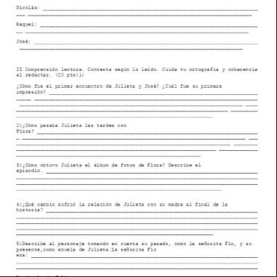
Prueba Encuentro Con Flo 4b1j1j
April 2020 24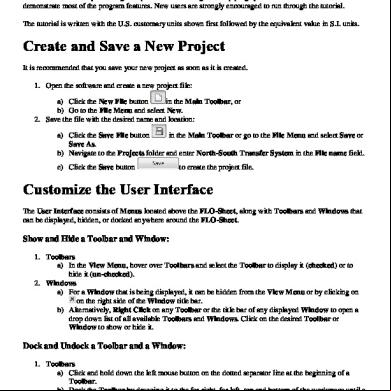
Pipe Flo Tutorial 4ae2m
November 2019 31
Flo Rida - Whistle 372z2g
November 2019 33More Documents from "Rob Zel" 374p1b
Flo Control 4j1l8
November 2022 0
Dell Vostr 3470 Sffi5s41tw10p1w (7v63k) (1) 1sv
April 2022 0
Nowoczesna Rehabilitacja Poudarowa 2es1n
November 2019 31
Clp-360 Service Manual c2p2h
October 2019 72
Intro Geroglificos Mayas 4r6s5t
April 2020 19