Lennox 6x6v5y
This document was ed by and they confirmed that they have the permission to share it. If you are author or own the copyright of this book, please report to us by using this report form. Report 3b7i
Overview 3e4r5l
& View Lennox as PDF for free.
More details w3441
- Words: 11,198
- Pages: 32
PA C KA G E D H E AT P U M P
KH
Landmark™ Rooftop Units 50 HZ
E N G I N E E R I N G D ATA
Bulletin No. 490149 December 2009
52.8 and 70.3 kW (15 and 20 Tons) Net Cooling Capacity − 46.0 to 57.7 kW (157 000 to 197 000 Btuh) Net Heating Capacity − 46.6 to 57.1 kW (159 000 to 196 000 Btuh) Optional Electric Heat - 10.4 to 62.5 kW MODEL NUMBER IDENTIFICATION K H A 240 S 4 B N 1 M Voltage M = 380/420V-3 phase-50hz
Brand/Family K = Landmark™ Unit Type H = Packaged Heat Pump Major Design Sequence A = 1st Generation Nominal Cooling Capacity - kW 180 = 52.8 kW 240 = 70.3 kW Cooling Efficiency S = Standard Efficiency
Minor Design Sequence 1 = 1st Revision 2 = 2nd Revision 3 = 3rd Revision Factory Installed Electric Heat N = No Heat E = 10.4 kW Electric Heat J = 20.8 kW Electric Heat K = 31.2 kW Electric Heat L = 41.6 kW Electric Heat P = 62.5 kW Electric Heat Blower Type B = Belt Drive Refrigerant Type 4 = R-410A
FEATURES AND BENEFITS
H L N
K G
M
D
C
J F I B
E
K
Landmark™ rooftop units from Lennox are the new standard for reliable, efficient rooftop units built for long-lasting performance that can significantly improve indoor and outdoor environments. Landmark rooftop units feature: • • • • • • • • • • •
R-410A Refrigerant - Environmentally friendly Scroll Compressors - Single speed scroll compressors are furnished on all models. Crankcase Heaters - Protect compressors from refrigerant liquid migration in the off cycle improving product reliability. High Pressure Switches - Protect compressor. Isolated Compressor Compartment - Allows performance check during normal compressor operation without disrupting airflow. Independent Motor Mounts - Allows for easy and efficient service access without removing the top . Downflow Airflow - Horizontal airflow with optional horizontal curb. Two Fork Lift Slots on Three Sides - Easy to pick up and transport units from almost any angle. Corrosion-Resistant Removable, Drain Pan - Provides application flexibility, durability and improved serviceability. Thermostatic Check/Expansion Valves - Provide peak cooling performance across the entire application range. MERV 8 or MERV 13 Filters - Available as field installed option, provide an enhanced level of indoor air quality, and can help the building qualify for additional Leadership in Energy and Environmental Design (LEED) credits.
Landmark™ Packaged Heat Pump 52.8 to 70.3 kW 50hz / Page 2
FEATURES AND BENEFITS Contents Accessory Dimensions . . . . . . . . . . . . . . . . . . . . . . . . . . . 23 Blower Data . . . . . . . . . . . . . . . . . . . . . . . . . . . . . . . . 14 Dimensions . . . . . . . . . . . . . . . . . . . . . . . . . . . . . . . . . 22 Electrical/Electric Heat Data . . . . . . . . . . . . . . . . . . . . . . . . 18 Electric Heat Capacities . . . . . . . . . . . . . . . . . . . . . . . . . . 18 Features And Benefits . . . . . . . . . . . . . . . . . . . . . . . . . . . . 2 Optional Conventional Temperature Control Systems . . . . . . . . . . . 20 Options / Accessories . . . . . . . . . . . . . . . . . . . . . . . . . . . . 8 Outdoor Sound Data . . . . . . . . . . . . . . . . . . . . . . . . . . . . 20 Ratings . . . . . . . . . . . . . . . . . . . . . . . . . . . . . . . . . . . 12 Specifications . . . . . . . . . . . . . . . . . . . . . . . . . . . . . . . .11 Unit Clearances . . . . . . . . . . . . . . . . . . . . . . . . . . . . . . 19 Weight Data . . . . . . . . . . . . . . . . . . . . . . . . . . . . . . . . 21
Defrost Control Provides a defrost cycle, if needed, every 30 or 60 or 90 minutes (adjustable) of compressor “on” time at outdoor coil temperature below 2°C. Pressure switch mounted on outdoor coil vapor line terminates defrost cycle.
E Reversing Valves 4-way interchange reversing valve effects a rapid change in direction of refrigerant flow resulting in quick changeover from cooling to heating and vice versa. Freezestats
PERFORMANCE/QUALITY Components bonded for grounding to meet safety standards for servicing required by Underwriters Laboratories (UL) and the International Electrotechnical Commission (IEC). Cooling performance is rated at test conditions included in Air-Conditioning, Heating and Refrigeration (AHRI) Standard 340/360-2007 while operating at rated voltage and air volumes. International Organization for Standardization (ISO) 9001 ed Manufacturing Quality System.
COOLING / HEATING SYSTEM Designed to maximize sensible and latent cooling performance at design conditions. System can operate in the cooling mode from –1°C to 52°C without any additional controls. R-410A Refrigerant Non-chlorine based, ozone friendly, R-410A.
Protects the indoor coil from damaging ice build-up due to conditions such as low/no airflow, or low refrigerant charge.
F Coil Construction Copper tube construction, enhanced rippled-edge aluminum fins, flared shoulder tubing connections, silver soldered construction for improved heat transfer. Factory leak tested. Indoor Coil
B Scroll Compressors Scroll compressors on all models for high performance, reliability and quiet operation. Resiliently mounted on rubber grommets for quiet operation. Compressor Crankcase Heaters Protects against refrigerant migration that can occur during low ambient operation.
C Check/Thermal Expansion Valves
Assures optimal performance throughout the application range. Removable element head.
D Filter/Driers High capacity bi-flow filter/drier protects the system from dirt and moisture. High Pressure Switches
Cross row circuiting with rifled copper tubing optimizes both sensible and latent cooling capacity. Outdoor Coil Two independent formed coils allows separation for cleaning. Condensate Drain Pan Plastic pan, sloped to meet drainage requirements of ASHRAE 62.1. Side or bottom drain connections.
G Outdoor Coil Fan Motors Thermal overload protected, totally enclosed, permanently lubricated ball bearings, shaft up, wire basket mount. Outdoor Coil Fans Polyvinyl Chloride (PVC) coated fan guard furnished.
Protects the compressor from overload conditions such as dirty condenser coils, blocked refrigerant flow, or loss of outdoor fan operation. Landmark™ Packaged Heat Pump 52.8 to 70.3 kW 50hz / Page 3
FEATURES AND BENEFITS COOLING / HEATING SYSTEM CONTINUED) REQUIRED SELECTIONS Cooling Capacity Specify nominal cooling capacity of the unit OPTIONS/ACCESSORIES Field Installed Condensate Drain Trap Available in copper or Polyvinyl Chloride (PVC). Low Ambient Kit Cycles the outdoor fan while allowing compressor operation in the cooling cycle. This intermittent fan operation allows the system to operate without icing the indoor coil and losing capacity. Designed for use in ambient temperatures no lower than –17°C. CABINET H Construction Heavy-gauge steel s and full perimeter heavy-gauge galvanized steel base rail provides structural integrity for transportation, handling, and installation. Base rails have rigging holes. Three sides of the base rail have forklift slots. Raised edges around duct and power entry openings in the bottom of the unit provide additional protection against water entering the building. Airflow Choice Units are available in downflow (vertical) or horizontal return air flow configuration. Horizontal air flow requires Horizontal Roof Curb. Horizontal Return Air Kit is also required if converting a downflow configured unit to horizontal air flow. Power Entry Electrical lines can be brought through the unit base or through horizontal access knock-outs
Exterior s
Horizontal Return Air Kit
Constructed of heavy-gauge, galvanized steel with a two-layer enamel paint finish.
Required for horizontal applications with Horizontal Roof Curb, contains with return air opening for field replacement of existing unit and to cover bottom return air opening in unit, see dimension drawings.
Insulation All s adjacent to conditioned air are fully insulated with nonhygroscopic fiberglass insulation. Unit base is fully insulated. The insulation also serves as an air seal to the roof curb, eliminating the need to add a seal during installation.
I BLOWER A wide selection of supply air blower options are available to meet a variety of airflow requirements.
Access s
Motor
Access s are provided for the economizer/filter section, heating/blower section, and the compressor/controls section.
Overload protected, equipped with ball bearings. Belt drive motors are offered on all models and are available in several different sizes to maximize air performance.
OPTIONS/ACCESSORIES Factory Installed Corrosion Protection A completely flexible immersed coating with an electrodeposited dry film process. (AST ElectroFin E-Coat) Meets Mil Spec MIL-P-53084, ASTM B117 Standard Method Salt Spray Testing, ASTM 1153 Standard Specification for Methyl Isobutyl Ketone. Hinged Access s Hinged access s for the filter section, the blower section and compressor/controls section. All hinged s have seals and quarter-turn latching handles to provide a tight air and water seal. Field Installed Coil Guards Painted, galvanized steel wire guards to protect outdoor coil. Not used with Hail Guards. Hail Guards Constructed of heavy gauge steel, painted to match cabinet, helps protect outdoor coils from hail damage. Not used with Coil Guards.
Landmark™ Packaged Heat Pump 52.8 to 70.3 kW 50hz / Page 4
Supply Air Blower Forward curved blades, double inlet, blower wheel is statically and dynamically balanced. Equipped with ball bearings and adjustable pulley (allows speed change),. Blower assembly slides out of unit for servicing. REQUIRED SELECTIONS Order blower motor horsepower and drive kit number required when base unit is ordered, see Drive Kit Specifications Table.
FEATURES AND BENEFITS CONTROLS J Unit Control All control voltage is provided via a 24V (secondary) transformer with built-in circuit breaker protection.
ELECTRICAL All units include terminal block and fuse block in power entry junction box for single power entry application.
Heat/Cool Staging - Capable of up to 2 heat / 2 cool staging with a third party DDC control system or thermostat.
REQUIRED SELECTIONS Voltage Choice
Low Voltage Terminal Block Provides screw terminal connections for thermostat or controller wiring.
OPTIONS/ACCESSORIES Field Installed
Night Setback Mode - Saves energy by closing outdoor air dampers and operating supply fan on thermostat demand only. OPTIONS/ACCESSORIES Field Installed
Specify when ordering base unit.
K Electric Heat Helix wound nichrome elements, individual element limit controls, wiring harness. Unit fuse block is furnished as standard. See Options / Accessories tables for ordering information
INDOOR AIR QUALITY L Air Filters Disposable 51 mm filters furnished as standard. OPTIONS/ACCESSORIES Field Installed High Efficiency Air Filters Disposable MERV 8 or MERV 13 (Minimum Efficiency Reporting Value based on ASHRAE 52.2) efficiency 51 mm pleated filters. Healthy Climate® UVC Germicidal Lamps
Smoke Detector Photoelectric type, installed in supply air section, return air section or both sections. Available with power board and single sensor (supply or return) or power board and two sensors (supply and return). Power board located in unit control compartment. Thermostats Control system and thermostat options. Aftermarket unit controller options. See page 20.
Germicidal lamps emit ultra-violet (UV-C) energy, which has been proven to be effective in reducing microbes such as viruses, bacteria, yeasts, and molds. This process either destroys the organism or controls its ability to reproduce. UV-C energy greatly reduces the growth and proliferation of mold and other bioaerosols (bacteria and viruses) on illuminated surfaces (particularly coil and drain pan). Lamps are field installed in the blower/evaporator coil section. All necessary hardware for installation is included. Lamps operate on 220V singlephase power supply. Step-down transformer may be ordered separately for 380/420V primary to 220V secondary units. Alternately, 220V power supply may be used to directly power the UVC ballast(s). Indoor Air Quality (CO2) Sensors
Monitors CO2 levels, reports to the Unit Controller which adjusts economizer dampers as needed.
Landmark™ Packaged Heat Pump 52.8 to 70.3 kW 50hz / Page 5
FEATURES AND BENEFITS SERVICEABILITY Designed to streamline general maintenance and decrease troubleshooting time. Marked & Color-Coded Wiring All electrical wiring is color-coded and marked to identify which components it is connecting. Electrical Plugs Positive connection electrical plugs are used to connect common accessories or maintenance parts for easy removal or installation. Access s Large access s are provided for quick and easy access to maintenance areas.
Standard Components A large number of common maintenance parts are standard throughout the entire range of sizes, reducing the need to carry a lot of different parts to the job or maintain in inventory. Compressor Compartment Compressors are located near the perimeter of the unit for easier access. Compressors are isolated from the condenser airflow allowing system operation checks to be done without changing the airflow across the outdoor coils.
Blower Access Supply air blower parts are located near the access door for easy servicing and adjustment. Check/Thermal Expansion Valve Access Check/Thermal expansion valves are located near the perimeter of the unit for easier access. Removable element head allows change out of element and bulb without removing the TXV. Coil Cleaning Independently formed condenser coils allow separation for easier cleaning.
Landmark™ Packaged Heat Pump 52.8 to 70.3 kW 50hz / Page 6
OPTIONS / ACCESSORIES
M ECONOMIZER/EXHAUST OPTIONS Factory or Field Installed
whichever has lower enthalpy. Horizontal Barometric Relief Dampers With Exhaust Hood
Economizer - Downflow or Horizontal With Outdoor Air Hood
For use when unit is configured for horizontal applications requiring an economizer.
Parallel gear-driven action return air and outdoor air dampers, plug-in connections to unit, nylon bearings, neoprene seals, 24-volt, fully-modulating, spring return motor, adjustable minimum damper position. Outdoor air hood is furnished.
Allows relief of excess air
Single sensible control is furnished with economizer. Outdoor air temperature sensor enables economizer if the outdoor temperature is less than the setpoint of the control. Outdoor Air Hood is included when economizer is factory installed and is furnished with economizer when ordered for field installation.
N Downflow Barometric Relief Dampers
Allows relief of excess air Aluminum blade dampers prevent blow back and outdoor air infiltration during off cycle. NOTE - When Downflow Barometric Relief Dampers are factory installed the Exhaust Hood must be ordered separately for field installation. When Downflow Barometric Relief Dampers are ordered for field installation the Exhaust Hood is furnished with the dampers. See Optional Accessories table. Field Installed
Aluminum blade dampers prevent blow back and outdoor air infiltration during off cycle. Field installed in return air duct. Exhaust hood with bird screen is furnished.
O Power Exhaust Fan Installs internal to unit for downflow applications only with economizer option. Provides exhaust air pressure relief. Interlocked to run when supply air blower is operating, fan runs when outdoor air dampers are 50% open (adjustable), motor is overload protected. Requires Economizer with Outdoor Air Hood and Downflow Barometric Relief Dampers. Dual fans are 508 mm diameter with 5 blades with (2) 224 W motors. OUTDOOR AIR OPTIONS Factory or Field Installed Outdoor Air Damper - Downflow or Horizontal With Air Hood Linked mechanical dampers, 0 to 25% (fixed) outdoor air adjustable, installs in unit. Includes outdoor air hood. Automatic model features fully modulating spring return damper motor with plug-in connection.
Single Economizer Enthalpy Control
Manual model features parallel blade, gear-driven dampers with adjustable fixed position.
Enthalpy sensor enables the economizer when the outdoor air enthalpy is below the configured setpoint.
Outdoor Air Hood is included when damper is factory installed and is furnished with damper when ordered for field installation.
Differential (Dual) Economizer Enthalpy Control
ROOF CURBS Nailer strip furnished, mates to unit, US National Roofing Contractors Approved, shipped knocked down. Downflow Clip Curbs - Uses interlocking tabs to fasten corners together. No tools required. Standard Curbs - Curb corners fasten together with furnished hardware. Adjustable Pitched Curb - Curbs are regionally sourced. Dimensions will vary based upon the source. your Lennox sales representative for a detailed cut sheet with applicable dimensions. Horizontal Converts unit from downflow to horizontal (side) air flow, return air is on unit, supply air is on curb, see dimension drawings. Curbs for rooftop applications meet National Roofing Code requirements. Requires Horizontal Return Air Kit. Available in 660, 762, 940 and 1041 mm heights. Optional Insulation Kit is available to help prevent sweating. CEILING DIFFS Ceiling Diffs (Flush or Step-Down) Aluminum grilles, large center grille, insulated diff box with flanges, hanging rings furnished, interior transition (even air flow), internally sealed (prevents recirculation), adapts to T-bar ceiling grids or plaster ceilings. Transitions (Supply and Return) Used with diffs, installs in roof curb, galvanized steel construction, flanges furnished for duct connection to diffs, fully insulated.
Order two single, enthalpy control kits. One is field installed in the return air section, the other in the outdoor air section. Allows the economizer control board to select between outdoor air or return air, Landmark™ Packaged Heat Pump 52.8 to 70.3 kW 50hz / Page 7
OPTIONS / ACCESSORIES Model Number
Item Description
Catalog Number
180
240
76M18
X
X
COOLING SYSTEM Condensate Drain Trap
Polyvinyl Chloride (PVC) - LTACDKP09/36
76M19
X
X
Corrosion Protection
Factory
O
O
Efficiency
Standard
O
O
Copper - LTACDKC09/36
55W73
X
X
R-410A
O
O
Belt Drive - 2.2 kW
Factory
O
Belt Drive - 3.7 kW
Factory
O
O
Belt Drive - 5.6 kW
Factory
O
O
Belt Drive - 7.5 kW
Factory
Drive Kits
Kit #1 446-604 rev/min
Factory
O
See Blower Data Tables for usage and selection
Kit #2 571-721 rev/min
Factory
O
Kit #3 571-721 rev/min
Factory
O
O
Kit #4 708-871 rev/min
Factory
O
O
Kit #5 788-988 rev/min
Factory
O
O
Kit #6 708-871 rev/min
Factory
O
O
Kit #7 788-988 rev/min
Factory
O
O
Kit #8 871-1071 rev/min
Factory
O
O
Low Ambient Kit
K1SNSR33CS1
Refrigerant Type BLOWER - SUPPLY AIR Motors
O
Kit #10 871-1071 rev/min
Factory
O
Kit #11 945-1138 rev/min
Factory
O
Coil Guards
C1GARD20C-1-
88K55
X
X
Hail Guards
C1GARD10C-1-
88K28
X
X
Smoke Detector - Supply or Return (Power board and one sensor)
C1SNSR44C-1
53W82
X
X
Smoke Detector - Supply and Return (Power board and two sensors)
C1SNSR43C-1
53W83
X
X
CABINET
CONTROLS
INDOOR AIR QUALITY Air Filters MERV 8 - C1FLTR15C-1-
54W67
X
X
MERV 13 - C1FLTR40C-1-
52W40
X
X
C1FLTR30C-1-
44N61
X
X
Sensor - Wall-mount, off-white plastic cover with LCD display
C0SNSR50AE1L
77N39
X
X
Sensor - Wall-mount, off-white plastic cover, no display
C0SNSR52AE1L
87N53
X
X
Sensor - Black plastic case with LCD display, rated for plenum mounting
C0SNSR51AE1L
87N52
X
X
C0MISC19AE1
87N54
X
X
C0MISC19AE1-
85L43
X
X
C0MISC16AE1-
90N43
X
X
C1UVCL10C-1
54W65
X
X
Healthy Climate® High Efficiency Air Filters 610 x 610 x 51 mm (Order 6 per unit) Replacement Media Filter With Metal Mesh Frame (includes non-pleated filter media) Indoor Air Quality (CO2) Sensors
Sensor - Wall-mount, black plastic case, no display, rated for plenum mounting CO2 Sensor Duct Mounting Kit - for downflow applications
Aspiration Box - for duct mounting non-plenum rated CO2 sensors (87N53 or 77N39) UVC Germicidal Light Kit
1
Healthy Climate® UVC Light Kit (220V-1ph)
Lamps operate on 220V single-phase power supply. Step-down transformer may be ordered separately for 380/420V primary to 220V secondary units. Alternately, 220V power supply may be used to directly power the UVC ballast(s).
1
NOTE - Catalog and model numbers shown are for ordering field installed accessories. OX - Configure To Order (Factory Installed) or Field Installed O = Configure To Order (Factory Installed) X = Field Installed
Landmark™ Packaged Heat Pump 52.8 to 70.3 kW 50hz / Page 8
OPTIONS / ACCESSORIES Model Number
Catalog Number
180
240
208/230V - 3 phase
Factory
O
O
460V - 3 phase
Factory
O
O
575V - 3 phase
Factory
O
O
10.4 kW
380/420V-3ph - C1EH0150C-1M
53W85
X
X
20.8 kW
380/420V-3ph - C1EH0300C21M
53W93
X
X
31.2 kW
380/420V-3ph - C1EH0450C21M
54W01
X
X
41.6 kW
380/420V-3ph - C1EH0600C21M
54W09
X
X
62.5 kW
380/420V-3ph - C1EH0900C-1M
54W13
K1ECON20C-1
54W77
OX
OX
Order 2 - C1SNSR64FF1
53W64
X
X
C1SNSR64FF1
53W64
X
X
C1DAMP50C
54W78
OX
OX
C1HOOD20C-1
85M26
X
X
LAGEDH18/24
16K99
X
X
Motorized Dampers with Outdoor Air Hood
K1DAMP20C-1
58W62
OX
OX
Manual Dampers With Outdoor Air Hood
C1DAMP10C-1
54W76
OX
OX
380/420V - C1PWRE10C-1M
54W73
X
X
Item Description ELECTRICAL Voltage 60 hz
ELECTRIC HEAT
X
ECONOMIZER Economizer Economizer - Downflow or Horizontal (Outdoor Air Hood furnished) Economizer Controls Differential Enthalpy Single Enthalpy Downflow Barometric Relief Dampers Barometric Relief Dampers with Field Installed Exhaust Hood Exhaust Hood for Factory Installed Downflow Barometric Relief Dampers Horizontal Barometric Relief Dampers Barometric Relief Dampers with Exhaust Hood OUTDOOR AIR Outdoor Air Dampers
POWER EXHAUST Standard Static 1
hen Downflow Barometric Relief Dampers are factory installed the Exhaust Hood (85M26) must be ordered separately for field installation. W When Downflow Barometric Relief Dampers are ordered for field installation the Exhaust Hood is furnished with the dampers.
NOTE - Catalog and model numbers shown are for ordering field installed accessories. OX - Configure To Order (Factory Installed) or Field Installed O = Configure To Order (Factory Installed) X = Field Installed
Landmark™ Packaged Heat Pump 52.8 to 70.3 kW 50hz / Page 9
OPTIONS / ACCESSORIES Item Description
Model Number
Catalog Number
180
240
ROOF CURBS - DOWNFLOW Clip Curb 203 mm height
C1CURB40CD1
26W32
X
X
356 mm height
LARMF18/30S-14
33K44
X
X
457 mm height
LARMF18/30S-18
33K45
X
X
610 mm height
LARMF18/30S-24
33K46
X
X
203 mm height
LARMF18/36-14
16K87
X
X
610 mm height
LARMF18/36-24
16K88
X
X
L1CURB55C
43W26
X
X
Standard
Adjustable Pitched Curb 203 mm height
ROOF CURBS - HORIZONTAL (REQUIRES HORIZONTAL RETURN AIR KIT) Clip Curb 660 mm height
LARMFH18/24S-26
33K47
X
X
940 mm height
LARMFH18/24S-37
45K70
X
X
660 mm height - rooftop applications
LARMFH18/24-26
97J33
X
X
940 mm height - slab applications
LARMFH18/24-37
38K53
X
X
for LARMFH18/24-26
C1INSU11C-1-
73K32
X
X
for LARMFH18/24-37
C1INSU13C-1-
73K34
X
X
C1HRAP10C-1-
87M00
X
X
RTD11-185
29G06
X
RTD11-275-R
29G07
FD11-185
29G10
FD11-275-R
29G11
LASRT18
19K01
LASRT21/24
19K02
Standard
Insulation Kit For Standard Horizontal Curbs
Horizontal Return Air Kit Required for Horizontal Applications with Roof Curb CEILING DIFFS Step-Down - Order one Flush - Order one Transitions (Supply and Return) - Order one NOTE - Catalog and model numbers shown are for ordering field installed accessories. OX - Configure To Order (Factory Installed) or Field Installed O = Configure To Order (Factory Installed) X = Field Installed
Landmark™ Packaged Heat Pump 52.8 to 70.3 kW 50hz / Page 10
X X X X X
SPECIFICATIONS General Data
Nominal kW (Tons) Model Number Efficiency Type Blower Type
Cooling Performance
Gross Cooling Capacity - kW (Btuh) 1 Net Cooling Capacity - kW (Btuh) AHRI Rated Air Flow - L/s (cfm) Total Unit Power - kW 1 EER (Btuh/Watt) 2 IEER (Btuh/Watt) Refrigerant Type Refrigerant Charge Circuit 1 Furnished Circuit 2 1 Heating Total High Heat Capacity - kW (Btuh) Performance Total Unit Power - kW 1 Coefficient of Performance 1 Total Low Heat Capacity - kW (Btuh) Total Unit Power (kW) 1 Coefficient of Performance Electric Heat Available - See page 9 Compressor Type (number) Outdoor Net face area (total) - m2 (sq. ft.) Coils Tube diameter - mm (in.) Number of rows Fins per m (Fins per inch) Outdoor Coil Motor - (No.) W (HP) Fans Motor rev/min Total Motor watts Diameter - (No.) mm (in.) Number of blades Total Air volume - L/s (cfm) Indoor Coils Net face area (total) - m2 (sq. ft.) Tube diameter - mm (in.) Number of rows Fins per m (Fins per inch) Drain connection - No. and size Expansion device type 3 Indoor Nominal Motor kW (HP) Blower Maximum usable motor kW (HP) and Kit # (rev/min range) Drive Selection Nominal Motor kW (HP) Maximum usable motor kW (HP) Kit # (rev/min range) Nominal Motor kW (HP) Maximum usable motor kW (HP) Kit # (rev/min range) Blower wheel nominal diameter x width - mm (in.) Filters Type of filter Number and size - mm (in.) Electrical characteristics
52.8 (15) 70.3 (20) KHA180S4B KHA240S4B Standard Standard Constant Air Constant Air Volume CAV Volume CAV 47.5 (162 000) 60.1 (205 000) 46.0 (157 000) 57.7 (197 000) 2830 (6000) 3540 (7500) 14.6 18.3 10.8 10.8 10.7 10.7 R-410A R-410A 9.53 kg (21 lbs. 0 oz.) 11.79 kg (26 lbs. 0 oz.) 9.53 kg (21 lbs. 0 oz.) 11.79 kg (26 lbs. 0 oz.) 46.6 (159 000) 57.1 (196 000) 13.7 17.0 3.4 3.4 27.0 (92 000) 33.1 (113 000) 12.8 15.8 2.1 2.1 10.4, 20.8, 31.2, 41.6 kW 10.4, 20.8, 31.2, 41.6, 62.5 kW Scroll (2) Scroll (2) 5.3 (57.0) 5.3 (57.0) 9.5 (3/8) 9.5 (3/8) 1.66 2 20 20 (4) 250 (1/3) (4) 250 (1/3) 896 896 1146 1146 (4) 610 (24) (4) 610 (24) 3 3 6275 (13 300) 6275 (13 300) 1.99 (21.4) 1.99 (21.4) 9.5 (3/8) 9.5 (3/8) 3 551 (14) 551 (14) (1) 1 in. FPT (1) 1 in. FPT Balance port TXV, removable head 2.2 (3) 3.7 (5) 2.6 (3.45) 4.3 (5.75) Kit 1 (446-604) Kit 3 (571-721) Kit 2 (571-721 Kit 4 (708-871) Kit 5 (788-988) 3.7 (5) 5.6 (7.5) 4.3 (5.75) 6.4 (8.6) Kit 3 (571-721) Kit 6 (708-871) Kit 4 (708-871) Kit 7 (788-988) Kit 5 (788-988) Kit 8 (871-1071) 5.6 (7.5) 7.5 (10) 6.4 (8.6) 8.6 (11.5) Kit 6 (708-871) Kit 7 (788-988) Kit 7 (788-988) Kit 10 (871-1071) Kit 8 (871-1071) Kit 11 (945-1138) (2) 381 x 381 (15 x 15) Fiberglass, disposable (6) 610 x 610 x 51 (24 x 24 x 2) 380/420V - 50 hertz - 3 phase with neutral
NOTE - Net capacity includes evaporator blower motor heat deduction. Gross capacity does not include evaporator blower motor heat deduction. 1 Tested at conditions included in the ULE certification program, which is based on AHRI Standard 340/360 while operating at rated voltage and air volumes: Cooling Ratings − 35°C (95°F) outdoor air temperature and 27°C (80°F) db/19°C (67°F) wb entering indoor coil air. High Temperature Heating Ratings − 8°C (47°F) db/6°C (43°F) wb outdoor air temperature and 21°C (70°F) entering indoor coil air. Low Temperature Heating Ratings − -8°C (17°F) db/-9°C (15°F) wb outdoor air temperature and 21°C (70°F) entering indoor coil air. 2 Integrated Energy Efficiency Ratio tested at conditions included in AHRI Standard 340/360 while operating at rated voltage and air volumes. 3 Using total air volume and system static pressure requirements determine from blower performance tables rev/min and motor output required. Maximum usable output of motors furnished are shown. If motors of comparable output are used, be sure to keep within the service factor limitations outlined on the motor nameplate. 4 Standard motor and drive kit furnished with unit.
Landmark™ Packaged Heat Pump 52.8 to 70.3 kW 50hz / Page 11
RATINGS NOTE − For Temperatures and Capacities not shown in tables, see bulletin − Cooling Unit Rating Table Correction Factor Data in Miscellaneous Engineering Data section.
52.8 KW STANDARD EFFICIENCY KHA180S4 (1ST STAGE) Entering Total Wet Air Total Bulb Volume Cool TemperCap. ature L/s kW 2265 25.1 17°C 2830 26.2 3400 27.1 2265 26.4 19°C 3400 27.6 3400 28.5 2265 27.7 22°C 2830 29.0 3400 29.9
18°C Comp. Sensible To Total Total Ratio (S/T) Motor Cool Input Cap. Dry Bulb kW 24°C 27°C 29°C kW 4.29 .72 .85 .97 24.1 4.36 .77 .92 1.00 25.2 4.40 .82 .98 1.00 26.1 4.37 .58 .70 .82 25.4 4.43 .60 .75 .89 26.6 4.49 .63 .80 .95 27.4 4.44 .44 .56 .68 26.7 4.51 .45 .59 .73 27.9 4.57 .46 .62 .78 28.7
Outdoor Air Temperature Entering Outdoor Coil 24°C 29°C Comp. Sensible To Total Total Comp. Sensible To Total Total Ratio (S/T) Ratio (S/T) Motor Cool Motor Cool Input Cap. Input Cap. Dry Bulb Dry Bulb kW 24°C 27°C 29°C kW kW 24°C 27°C 29°C kW 4.76 .73 .87 .99 23.2 5.29 .75 .89 1.00 22.0 4.82 .78 .94 1.00 24.1 5.34 .80 .96 1.00 22.9 4.88 .83 .99 1.00 25.0 5.40 .85 1.00 1.00 23.9 4.83 .58 .71 .84 24.4 5.36 .59 .72 .85 23.2 4.90 .61 .76 .91 25.4 5.42 .62 .78 .93 24.2 4.95 .64 .81 .97 26.2 5.47 .65 .83 .99 24.8 4.91 .44 .57 .69 25.6 5.43 .45 .57 .70 24.4 4.98 .46 .60 .74 26.7 5.50 .46 .61 .76 25.4 5.04 .47 .63 .79 27.5 5.55 .47 .65 .81 26.1
Comp. Motor Input kW 5.88 5.95 6.00 5.96 6.02 6.07 6.04 6.10 6.15
35°C Sensible To Total Ratio (S/T) Dry Bulb 24°C 27°C 29°C .76 .91 1.00 .82 .98 1.00 .88 1.00 1.00 .60 .74 .88 .63 .80 .95 .67 .86 1.00 .45 .58 .72 .46 .62 .78 .48 .66 .84
Comp. Motor Input kW 16.44 16.59 16.71 16.57 16.68 16.75 16.72 16.82 16.91
52°C Sensible To Total Ratio (S/T) Dry Bulb 24°C 27°C 29°C .83 .98 1.00 .90 1.00 1.00 .97 1.00 1.00 .64 .81 .96 .69 .88 1.00 .73 .95 1.00 .47 .63 .79 .49 .68 .86 .51 .73 .93
52.8 KW STANDARD EFFICIENCY KHA180S4 (2ND STAGE) Entering Total Wet Air Total Bulb Volume Cool TemperCap. ature L/s kW 2265 46.5 17°C 2830 48.6 3400 50.2 2265 49.0 19°C 3400 51.2 3400 52.8 2265 51.4 22°C 2830 53.7 3400 55.3
27°C Comp. Sensible To Total Total Ratio (S/T) Motor Cool Input Cap. Dry Bulb kW 24°C 27°C 29°C kW 9.95 .73 .87 .98 43.3 10.08 .79 .94 1.00 45.2 10.17 .84 .99 1.00 46.9 10.10 .58 .71 .84 45.6 10.23 .61 .76 .91 47.5 10.33 .64 .82 .97 48.9 10.24 .44 .57 .69 47.9 10.39 .46 .60 .74 49.9 10.49 .47 .63 .80 51.3
Outdoor Air Temperature Entering Outdoor Coil 35°C 43°C Comp. Sensible To Total Total Comp. Sensible To Total Total Ratio (S/T) Ratio (S/T) Motor Cool Motor Cool Input Cap. Input Cap. Dry Bulb Dry Bulb kW 24°C 27°C 29°C kW kW 24°C 27°C 29°C kW 11.68 .76 .90 1.00 39.6 13.78 .79 .94 1.00 35.4 11.79 .81 .97 1.00 41.5 13.91 .85 .99 1.00 37.4 11.90 .87 1.00 1.00 43.3 14.03 .91 1.00 1.00 39.0 11.82 .60 .73 .87 41.9 13.94 .61 .76 .91 37.3 11.94 .63 .79 .95 43.5 14.05 .65 .83 .98 38.6 12.04 .66 .85 .99 44.6 14.13 .69 .89 1.00 39.6 11.97 .45 .58 .71 44.0 14.08 .46 .60 .74 39.3 12.10 .46 .62 .77 45.7 14.21 .47 .64 .81 40.6 12.20 .48 .66 .83 46.9 14.29 .49 .68 .87 41.6
52.8 KW STANDARD EFFICIENCY KHA180S4 - HEATING CAPACITY Indoor Coil Air Volume 21°C Dry Bulb L/s 2265 2830 3400
18°C
Air Temperature Entering Outdoor Coil -4°C
7°C
-15°C
-28°C
Total Heating Capacity
Comp. Motor Input
Total Heating Capacity
Comp. Motor Input
Total Heating Capacity
Comp. Motor Input
Total Heating Capacity
Comp. Motor Input
Total Heating Capacity
Comp. Motor Input
kW 54.6 55.3 56.1
kW 11.5 11.0 10.6
kW 44.9 45.6 46.4
kW 10.8 10.3 10.0
kW 29.1 29.8 30.4
kW 10.1 9.5 9.2
kW 21.0 21.7 22.2
kW 8.8 8.3 8.0
kW 10.2 10.8 11.3
kW 6.5 6.0 5.7
Landmark™ Packaged Heat Pump 52.8 to 70.3 kW 50hz / Page 12
RATINGS NOTE − For Temperatures and Capacities not shown in tables, see bulletin − Cooling Unit Rating Table Correction Factor Data in Miscellaneous Engineering Data section.
70.3 KW STANDARD EFFICIENCY KHA240S4 (1ST STAGE) Entering Total Wet Air Total Bulb Volume Cool TemperCap. ature L/s kW 3020 32.6 17°C 3775 34.2 4530 35.5 3020 34.6 19°C 4530 36.2 4530 37.3 3020 36.5 22°C 3775 38.2 4530 39.3
18°C Comp. Sensible To Total Total Ratio (S/T) Motor Cool Input Cap. Dry Bulb kW 24°C 27°C 29°C kW 5.14 .72 .85 .97 31.4 5.22 .77 .92 1.00 32.8 5.29 .82 .98 1.00 34.0 5.24 .57 .69 .81 33.3 5.33 .60 .75 .88 34.7 5.40 .63 .80 .95 35.8 5.34 .44 .55 .67 35.1 5.44 .45 .58 .72 36.5 5.51 .46 .62 .77 37.7
Outdoor Air Temperature Entering Outdoor Coil 24°C 29°C Comp. Sensible To Total Total Comp. Sensible To Total Total Ratio (S/T) Ratio (S/T) Motor Cool Motor Cool Input Cap. Input Cap. Dry Bulb Dry Bulb kW 24°C 27°C 29°C kW kW 24°C 27°C 29°C kW 5.75 .73 .86 .99 30.0 6.44 .74 .88 1.00 28.5 5.82 .78 .93 1.00 31.4 6.51 .80 .96 1.00 29.8 5.90 .83 .99 1.00 32.6 6.57 .85 1.00 1.00 31.1 5.86 .58 .71 .83 31.8 6.54 .58 .72 .85 30.3 5.93 .61 .76 .91 33.1 6.60 .62 .77 .92 31.6 6.00 .64 .81 .97 34.2 6.66 .65 .83 .99 32.3 5.95 .44 .56 .68 33.6 6.63 .44 .57 .69 32.0 6.04 .45 .59 .73 34.9 6.71 .45 .60 .75 33.2 6.12 .46 .63 .79 36.0 6.78 .47 .64 .81 34.2
Comp. Motor Input kW 7.20 7.28 7.34 7.31 7.38 7.42 7.41 7.48 7.53
35°C Sensible To Total Ratio (S/T) Dry Bulb 24°C 27°C 29°C .76 .90 1.00 .82 .98 1.00 .87 1.00 1.00 .60 .73 .87 .63 .80 .95 .67 .86 1.00 .44 .58 .71 .46 .62 .77 .48 .66 .83
Comp. Motor Input kW 20.66 20.86 20.99 20.81 20.92 21.00 21.00 21.12 21.19
52°C Sensible To Total Ratio (S/T) Dry Bulb 24°C 27°C 29°C .85 1.00 1.00 .93 1.00 1.00 .99 1.00 1.00 .65 .83 .99 .71 .91 1.00 .76 .98 1.00 .48 .64 .81 .50 .70 .89 .52 .75 .96
70.3 KW STANDARD EFFICIENCY KHA240S4 (2ND STAGE) Entering Total Wet Air Total Bulb Volume Cool TemperCap. ature L/s kW 3020 59.5 17°C 3775 62.1 4530 64.4 3020 63.0 19°C 4530 65.7 4530 67.6 3020 66.5 22°C 3775 69.2 4530 71.1
27°C Comp. Sensible To Total Total Ratio (S/T) Motor Cool Input Cap. Dry Bulb kW 24°C 27°C 29°C kW 12.24 .75 .89 1.00 55.2 12.39 .81 .96 1.00 57.7 12.53 .86 1.00 1.00 60.2 12.44 .60 .73 .86 58.6 12.60 .63 .79 .93 60.8 12.71 .66 .84 .99 62.5 12.66 .45 .58 .70 61.8 12.83 .46 .62 .76 64.2 12.96 .47 .65 .82 65.9
Outdoor Air Temperature Entering Outdoor Coil 35°C 43°C Comp. Sensible To Total Total Comp. Sensible To Total Total Ratio (S/T) Ratio (S/T) Motor Cool Motor Cool Input Cap. Input Cap. Dry Bulb Dry Bulb kW 24°C 27°C 29°C kW kW 24°C 27°C 29°C kW 14.49 .77 .92 1.00 50.6 17.23 .81 .96 1.00 44.9 14.64 .84 .99 1.00 53.1 17.38 .87 1.00 1.00 47.7 14.78 .89 1.00 1.00 55.4 17.56 .94 1.00 1.00 49.6 14.69 .60 .75 .89 53.5 17.42 .62 .78 .93 47.2 14.82 .65 .82 .97 55.3 17.54 .67 .85 1.00 48.9 14.93 .68 .88 1.00 56.8 17.64 .71 .92 1.00 50.0 14.88 .45 .59 .73 56.4 17.62 .46 .61 .76 50.0 15.04 .47 .63 .79 58.4 17.76 .48 .66 .83 51.5 15.17 .48 .67 .85 59.8 17.85 .50 .71 .90 52.5
70.3 KW STANDARD EFFICIENCY KHA240S4 - HEATING CAPACITY Indoor Coil Air Volume 21°C Dry Bulb L/s 3020 3775 4530
18°C
Air Temperature Entering Outdoor Coil -4°C
7°C
-15°C
-28°C
Total Heating Capacity
Comp. Motor Input
Total Heating Capacity
Comp. Motor Input
Total Heating Capacity
Comp. Motor Input
Total Heating Capacity
Comp. Motor Input
Total Heating Capacity
Comp. Motor Input
kW 67.3 68.9 70.2
kW 13.9 13.2 12.7
kW 54.9 56.5 57.8
kW 13.0 12.3 11.8
kW 35.9 36.8 37.9
kW 12.2 11.4 10.9
kW 25.1 26.5 27.5
kW 10.7 9.9 9.5
kW 12.0 13.3 14.4
kW 8.0 7.2 6.8
Landmark™ Packaged Heat Pump 52.8 to 70.3 kW 50hz / Page 13
BLOWER DATA BLOWER TABLE INCLUDES RESISTANCE FOR BASE UNIT ONLY WITH DRY INDOOR COIL & AIR FILTERS IN PLACE FOR ALL UNITS ADD: 1 - Wet indoor coil air resistance of selected unit. 2 - Any factory installed options air resistance (electric heat, economizer, etc.) 3 - Any field installed accessories air resistance (electric heat, duct resistance, diff, etc.) Then determine from blower table blower motor output and drive required. See page 16 for wet coil and option/accessory air resistance data. See page 16 for factory installed drive kit specifications. MINIMUM AIR VOLUME REQUIRED FOR USE WITH OPTIONAL ELECTRIC HEAT All units require 2830 L/s (6000 cfm) minimum air with electric heat. Air Volume
L/s
cfm
TOTAL STATIC PRESSURE - Pa (Inches Water Gauge) 100 (0.40) rev/ min
150 (0.60)
kW BHP rev/ min
kW BHP
200 (0.80) rev/ min
kW BHP
250 (1.00) rev/ min
kW BHP
300 (1.20) rev/ min
kW
BHP
350 (1.40) rev/ min
kW
BHP
2240
4750
575 0.82 1.10 660 1.08 1.45
740
1.34 1.80
810
1.60 2.15
870
1.86
2.50
930
2.13
2.85
2360
5000
585 0.93 1.25 670 1.19 1.60
750
1.45 1.95
815
1.72 2.30
880
2.01
2.70
940
2.27
3.05
2480
5250
595 1.01 1.35 680 1.27 1.70
755
1.57 2.10
825
1.86 2.50
890
2.16
2.90
945
2.42
3.25
2595
5500
605 1.08 1.45 690 1.38 1.85
765
1.68 2.25
835
1.98 2.65
895
2.27
3.05
955
2.57
3.45
2715
5750
615 1.19 1.60 700 1.49 2.00
775
1.83 2.45
840
2.13 2.85
905
2.42
3.25
960
2.72
3.65
2830
6000
630 1.30 1.75 710 1.60 2.15
785
1.94 2.60
850
2.27 3.05
910
2.57
3.45
970
2.91
3.90
2950
6250
640 1.42 1.90 720 1.75 2.35
795
2.09 2.80
860
2.42 3.25
920
2.76
3.70
975
3.09
4.15
3070
6500
650 1.53 2.05 730 1.86 2.50
805
2.24 3.00
870
2.57 3.45
930
2.95
3.95
985
3.28
4.40
3185
6750
665 1.64 2.20 745 2.01 2.70
815
2.39 3.20
880
2.76 3.70
940
3.13
4.20
995
3.47
4.65
3305
7000
675 1.75 2.35 755 2.16 2.90
825
2.54 3.40
890
2.95 3.95
950
3.32
4.45
1005 3.69
4.95
3420
7250
690 1.94 2.60 765 2.31 3.10
835
2.72 3.65
900
3.09 4.15
955
3.47
4.65
1015 3.91
5.25
3540
7500
700 2.05 2.75 775 2.46 3.30
845
2.87 3.85
910
3.32 4.45
965
3.69
4.95
1020 4.10
5.50
3660
7750
715 2.24 3.00 790 2.65 3.55
855
3.06 4.10
920
3.50 4.70
975
3.91
5.25
1030 4.33
5.80
3775
8000
725 2.39 3.20 800 2.83 3.80
865
3.24 4.35
930
3.69 4.95
985
4.10
5.50
1040 4.55
6.10
995
3895
8250
740 2.54 3.40 810 2.98 4.00
880
3.47 4.65
940
3.91 5.25
4.36
5.85
1050 4.81
6.45
4010
8500
750 2.72 3.65 825 3.21 4.30
890
3.65 4.90
950
4.14 5.55 1005 4.59
6.15
1060 5.07
6.80
4130
8750
765 2.91 3.90 835 3.39 4.55
900
3.88 5.20
960
4.36 5.85 1015 4.81
6.45
1070 5.33
7.15
4250
9000
780 3.13 4.20 850 3.62 4.85
910
4.10 5.50
970
4.59 6.15 1025 5.07
6.80
1080 5.59
7.50
4365
9250
790 3.32 4.45 860 3.84 5.15
925
4.36 5.85
985
4.88 6.55 1040 5.37
7.20
1090 5.85
7.85
4485
9500
805 3.54 4.75 875 4.06 5.45
935
4.59 6.15
995
5.15 6.90 1050 5.67
7.60
1100 6.15
8.25
4600
9750
820 3.77 5.05 885 4.29 5.75
950
4.88 6.55 1005 5.37 7.20 1060 5.93
7.95
1110 6.45
8.65
4720 10 000 835 4.03 5.40 900 4.59 6.15
960
5.11 6.85 1015 5.67 7.60 1070 6.23
8.35
1120 6.75
9.05 9.55
4835 10 250 845 4.21 5.65 910 4.81 6.45
970
5.37 7.20 1030 5.97 8.00 1080 6.52
8.75
1135 7.12
4955 10 500 860 4.47 6.00 925 5.11 6.85
985
5.70 7.65 1040 6.26 8.40 1095 6.86
9.20
1145 7.46 10.00
5075 10 750 875 4.77 6.40 940 5.41 7.25 1000 6.00 8.05 1055 6.60 8.85 1105 7.20
9.65
1155 7.79 10.45
5190
11 000
890 5.07 6.80 950 5.67 7.60 1010 6.30 8.45 1065 6.94 9.30 1115 7.49 10.05 1165 8.13 10.90 CONTINUED ON NEXT PAGE
Landmark™ Packaged Heat Pump 52.8 to 70.3 kW 50hz / Page 14
BLOWER DATA BLOWER TABLE INCLUDES RESISTANCE FOR BASE UNIT ONLY WITH DRY INDOOR COIL & AIR FILTERS IN PLACE FOR ALL UNITS ADD: 1 - Wet indoor coil air resistance of selected unit. 2 - Any factory installed options air resistance (electric heat, economizer, etc.) 3 - Any field installed accessories air resistance (electric heat, duct resistance, diff, etc.) Then determine from blower table blower motor output and drive required. See page 16 for wet coil and option/accessory air resistance data. See page 16 for factory installed drive kit specifications. MINIMUM AIR VOLUME REQUIRED FOR USE WITH OPTIONAL ELECTRIC HEAT All units require 2830 L/s (6000 cfm) minimum air with electric heat. Air Volume
TOTAL STATIC PRESSURE - Pa (Inches Water Gauge) 400 (1.60) kW
BHP
450 (1.80) rev/ min
kW
BHP
500 (2.00) rev/ min
kW
550 (2.20)
BHP
rev/ min
kW
BHP
600 (2.40) rev/ min
kW
BHP
650 (2.60)
L/s
cfm
rev/ min
rev/ min
kW
BHP
2240
4750
985 2.39 3.20
1040 2.65 3.55
1085 2.91 3.90
1135 3.17 4.25
1180 3.47 4.65
1225 3.73 5.00
2360
5000
995 2.54 3.40
1045 2.83 3.80
1095 3.09 4.15
1140 3.36 4.50
1185 3.65 4.90
1230 3.95 5.30
2480
5250
1000 2.72 3.65
1050 2.98 4.00
1100 3.28 4.40
1150 3.58 4.80
1195 3.88 5.20
1235 4.18 5.60
2595
5500
1010 2.87 3.85
1060 3.17 4.25
1110 3.50 4.70
1155 3.80 5.10
1200 4.10 5.50
1240 4.40 5.90
2715
5750
1015 3.06 4.10
1065 3.36 4.50
1115 3.69 4.95
1160 3.99 5.35
1205 4.33 5.80
1250 4.66 6.25
2830
6000
1025 3.24 4.35
1075 3.58 4.80
1120 3.88 5.20
1170 4.21 5.65
1215 4.55 6.10
1255 4.88 6.55
2950
6250
1030 3.43 4.60
1080 3.77 5.05
1130 4.10 5.50
1175 4.44 5.95
1220 4.81 6.45
1265 5.15 6.90
3070
6500
1040 3.62 4.85
1090 3.99 5.35
1140 4.36 5.85
1185 4.70 6.30
1225 5.03 6.75
1270 5.41 7.25
3185
6750
1045 3.80 5.10
1095 4.18 5.60
1145 4.55 6.10
1190 4.92 6.60
1235 5.29 7.10
1275 5.67 7.60
3305
7000
1055 4.03 5.40
1105 4.44 5.95
1155 4.81 6.45
1200 5.18 6.95
1240 5.56 7.45
1285 5.97 8.00
3420
7250
1065 4.29 5.75
1115 4.66 6.25
1160 5.03 6.75
1205 5.44 7.30
1250 5.85 7.85
1290 6.23 8.35
3540
7500
1075 4.51 6.05
1125 4.92 6.60
1170 5.33 7.15
1215 5.70 7.65
1260 6.15 8.25
1300 6.52 8.75
3660
7750
1080 4.74 6.35
1130 5.15 6.90
1180 5.59 7.50
1225 6.00 8.05
1265 6.41 8.60
1305 6.82 9.15
3775
8000
1090 5.00 6.70
1140 5.41 7.25
1185 5.85 7.85
1230 6.26 8.40
1275 6.71 9.00
1315 7.16 9.60
3895
8250
1100 5.26 7.05
1150 5.70 7.65
1195 6.15 8.25
1240 6.60 8.85
1280 7.01 9.40
1325 7.49 10.05
4010
8500
1110 5.52 7.40
1160 6.00 8.05
1205 6.45 8.65
1250 6.90 9.25
1290 7.35 9.85
1330 7.79 10.45
4130
8750
1120 5.78 7.75
1165 6.23 8.35
1215 6.75 9.05
1255 7.20 9.65
1300 7.68 10.30 1340 8.13 10.90
4250
9000
1130 6.08 8.15
1175 6.52 8.75
1220 7.01 9.40
1265 7.53 10.10 1310 8.05 10.80 1350 8.50 11.40
4365
9250
1140 6.38 8.55
1185 6.86 9.20
1230 7.35 9.85
1275 7.87 10.55 1315 8.35 11.20
4485
9500
1150 6.67 8.95
1195 7.16 9.60
1240 7.68 10.30 1285 8.24 11.05
4600
9750
1160 7.01 9.40
4720 10 000 1170 7.31 9.80
---
---
---
---
---
---
---
---
---
1205 7.49 10.05 1250 8.05 10.80 1295 8.58 11.50
---
---
---
---
---
---
1215 7.83 10.50 1260 8.39 11.25
---
---
---
---
---
---
---
---
---
4835 10 250 1180 7.64 10.25 1225 8.20 11.00
---
---
---
---
---
---
---
---
---
---
---
---
4955 10 500 1190 7.98 10.70 1235 8.54 11.45
---
---
---
---
---
---
---
---
---
---
---
---
5075 10 750 1200 8.35 11.20
---
---
---
---
---
---
---
---
---
---
---
---
---
---
---
5190 11 000
---
---
---
---
---
---
---
---
---
---
---
---
---
---
---
---
---
---
Landmark™ Packaged Heat Pump 52.8 to 70.3 kW 50hz / Page 15
BLOWER DATA FACTORY INSTALLED BELT DRIVE KIT SPECIFICATIONS Nominal kW
Nominal hp
Maximum kW
Maximum hp
Drive Kit Number
Rev/min Range
2.2
3
2.6
3.45
1
446 - 604
2.2
3
2.6
3.45
2
571 - 721
3.7
5
4.3
5.75
3
571 - 721
3.7
5
4.3
5.75
4
708 - 871
3.7
5
4.3
5.75
5
788 - 988
5.6
7.5
6.4
8.63
6
708 - 871
5.6
7.5
6.4
8.63
7
788 - 988
5.6
7.5
6.4
8.63
8
871 - 1071
7.5
10
8.6
11.50
7
788 - 988
7.5
10
8.6
11.50
10
871 - 1071
7.5
10
8.6
11.50
11
945 - 1138
NOTE - Using total air volume and system static pressure requirements determine from blower performance tables rev/min and motor output required. Maximum usable output of motors furnished are shown. If motors of comparable output are used, be sure to keep within the service factor limitations outlined on the motor nameplate.
FACTORY INSTALLED OPTIONS/FIELD INSTALLED ACCESSORY AIR RESISTANCE Wet Indoor Coil Air Volume L/s
cfm
180 Pa
in. w.g.
240 Pa
in. w.g.
Filters Electric Heat Pa
in. w.g.
Economizer
Pa
in. w.g.
MERV 8 Pa
in. w.g.
MERV 13 Pa
in. w.g.
Horizontal Roof Curb Pa
in. w.g.
1890
4000
5
0.02
10
0.04
---
---
---
---
10
0.04
15
0.06
15
0.06
2005
4250
5
0.02
10
0.04
---
---
---
---
10
0.04
15
0.06
17
0.07
2125
4500
5
0.02
12
0.05
---
---
---
---
10
0.04
17
0.07
17
0.07
2240
4750
5
0.02
12
0.05
---
---
---
---
10
0.04
17
0.07
20
0.08
2360
5000
5
0.02
12
0.05
---
---
---
---
12
0.05
17
0.07
20
0.08
2475
5250
5
0.02
15
0.06
---
---
---
---
12
0.05
17
0.07
22
0.09
2595
5500
5
0.02
17
0.07
---
---
---
---
12
0.05
17
0.07
25
0.10
2715
5750
7
0.03
17
0.07
---
---
---
---
12
0.05
20
0.08
27
0.11
2830
6000
7
0.03
20
0.08
2
.01
---
---
12
0.05
20
0.08
27
0.11
2950
6250
7
0.03
20
0.08
2
.01
2
0.01
12
0.05
20
0.08
30
0.12
3065
6500
7
0.03
22
0.09
2
.01
5
0.02
12
0.05
20
0.08
32
0.13
3185
6750
10
0.04
25
0.10
2
.01
7
0.03
12
0.05
20
0.08
35
0.14
3305
7000
10
0.04
25
0.10
2
.01
10
0.04
15
0.06
20
0.08
37
0.15
3420
7250
10
0.04
27
0.11
2
.01
12
0.05
15
0.06
22
0.09
40
0.16
3540
7500
12
0.05
30
0.12
2
.01
15
0.06
15
0.06
22
0.09
42
0.17
3775
8000
12
0.05
32
0.13
5
.02
22
0.09
15
0.06
22
0.09
47
0.19
4010
8500
15
0.06
37
0.15
5
.02
27
0.11
15
0.06
22
0.09
52
0.21
4245
9000
17
0.07
40
0.16
10
.04
35
0.14
17
0.07
25
0.10
60
0.24
4485
9500
20
0.08
45
0.18
12
.05
40
0.16
17
0.07
25
0.10
65
0.26
4720
10 000
20
0.08
50
0.20
15
.06
47
0.19
17
0.07
27
0.11
72
0.29
4955
10 500
22
0.09
55
0.22
22
.09
55
0.22
17
0.07
27
0.11
77
0.31
5191
11 000
27
0.11
60
0.24
27
.11
62
0.25
20
0.08
27
0.11
85
0.34
Landmark™ Packaged Heat Pump 52.8 to 70.3 kW 50hz / Page 16
BLOWER DATA POWER EXHAUST FAN PERFORMANCE Return Air System Static Pressure Pa in. w.g. 0 0.00 12 0.05 25 0.10 37 0.15 50 0.20 62 0.25 75 0.30 87 0.35 100 0.40 112 0.45 125 0.50
CEILING DIFF AIR RESISTANCE Air Volume L/s cfm 2360 5000 2455 5200 2550 5400 2645 5600 2735 5800 2830 6000 2925 6200 3020 6400 3065 6500 3115 6600 3210 6800 3305 7000 3400 7200 3490 7400 3540 7500 3585 7600 3775 8000 4010 8500 4245 9000 4485 9500 4720 10 000 4955 10 500 5190 11 000
RTD11-185 1 Side/2 Ends 2 Ends Open Open Pa in. w.g. Pa in. w.g. 127 0.51 109 0.44 139 0.56 119 0.48 152 0.61 129 0.52 164 0.66 139 0.56 177 0.71 147 0.59 189 0.76 157 0.63 199 0.80 169 0.68 214 0.86 179 0.72 --------229 0.92 191 0.77 246 0.99 206 0.83 256 1.03 216 0.87 271 1.09 229 0.92 286 1.15 241 0.97 --------298 1.20 254 1.02 ---------------------------------------------------------
Step-Down Diff
Flush Diff
RTD11-275 All Ends & 1 Side/2 Ends 2 Ends Open Sides Open Open Pa in. w.g. Pa in. w.g. Pa in. w.g. 97 0.39 - - ------104 0.42 - - ------112 0.45 - - ------119 0.48 - - ------127 0.51 - - ------137 0.55 90 0.36 77 0.31 147 0.59 - - ------157 0.63 - - --------- - - 104 0.42 90 0.36 167 0.67 - - ------179 0.72 - - ------189 0.76 122 0.49 102 0.41 199 0.80 - - ------209 0.84 - - --------- - - 127 0.51 114 0.46 219 0.88 - - --------- - - 147 0.59 122 0.49 --- - - 172 0.69 144 0.58 --- - - 196 0.79 167 0.67 --- - - 221 0.89 186 0.75 --- - - 249 1.00 209 0.84 --- - - 274 1.10 229 0.92 --- - - 301 1.21 251 1.01
CEILING DIFF AIR THROW DATA Air Volume
Model No.
180
L/s
cfm
2645 2735 2830 2925 3020 3115
5600 5800 6000 6200 6400 6600
Effective Throw Range RTD11-185 FD11-185 Step-Down Flush m ft. m ft. 12 - 15 39 - 49 9 - 11 28 - 37 13 - 16 42 - 51 9 - 12 29 - 38 13 - 16 44 - 54 12 - 15 40 - 50 14 - 17 45 - 55 13 - 16 42 - 51 14 - 17 46 - 55 13 - 16 43 - 52 14 - 17 47 - 56 14 - 17 45 - 56
All Ends & Sides Open Pa in. w.g. --------------------67 0.27 --------77 0.31 --------90 0.36 --------102 0.41 ----107 0.43 124 0.50 144 0.58 162 0.65 182 0.73 199 0.80 219 0.88
Air Volume
1
Throw is the horizontal or vertical distance an airstream travels on leaving the outletor diff before the maximum velocity is reduced to 15 m (50 ft.) per minute. Four sides open.
1
Air Volume Exhausted L/s cfm 3395 7195 3230 6845 3040 6440 2795 5925 2545 5395 2275 4820 1990 4215 1690 3580 1380 2925 1055 2235 725 1535
Model No.
240
L/s
cfm
3400 3490 3585 3680 3775 3870 3965 4060 4155
7200 7400 7600 7800 8000 8200 8400 8600 8800
FD11-185
FD11-275
Pa in. w.g. 67 0.27 75 0.30 82 0.33 90 0.36 97 0.39 104 0.42 114 0.46 124 0.50 ----134 0.54 144 0.58 154 0.62 164 0.66 174 0.70 ----184 0.74 -----------------------------
Pa in. w.g. --------------------72 0.29 --------85 0.34 --------99 0.40 --------112 0.45 ----124 0.50 142 0.57 164 0.66 184 0.74 201 0.81 221 0.89 239 0.96
Effective Throw Range RTD11-185 FD11-185 Step-Down Flush m ft. m ft. 10 - 12 33 - 38 8 - 11 26 - 35 11 - 12 35 - 40 9 - 11 28 - 37 11 - 12 36 - 41 9 - 11 29 - 38 12 - 13 38 - 43 12 - 15 40 - 50 12 - 13 39 - 44 13 - 16 42 - 51 12 - 14 41 - 46 13 - 16 43 - 52 13 - 15 43 - 49 13 - 16 44 - 54 13 - 15 44 - 50 14 - 17 46 - 57 14 - 17 47 - 55 15 - 18 48 - 59 1
Landmark™ Packaged Heat Pump 52.8 to 70.3 kW 50hz / Page 17
ELECTRICAL/ELECTRIC HEAT DATA 1
Voltage - 50hz 3 Phase with neutral
Compressor 1 Compressor 2 Outdoor Fan Motors
Maximum Overcurrent Protection
Rated Load Amps
12.2
16.7
101
111
Rated Load Amps
12.2
16.7
Locked Rotor Amps
101
111
4
4
Full Load Amps
1.3
1.3
(total) Full Load Amps
(5.2) 1.3
(5.2) 1.3
(total)
(2.6)
(2.6)
kW
2.2
3.7
5.6
3.7
5.6
7.5
Full Load Amps
5
7.8
11.8
7.8
11.8
15.2
Unit Only
45
50
50
60
70
70
With (2) 0.25 kW (0.33 HP)
50
50
50
60
70
70
Power Exhaust Unit Only
38
41
45
51
55
58
With (2) 0.25 kW (0.33 HP)
41
44
48
54
58
61
Electric Heat Voltage
420
420
420
420
420
420
Unit+
10.4 kW
60
70
70
80
80
90
Electric Heat
20.8 kW
80
80
90
100
100
100
31.2 kW
100
100
110
110
125
125
41.6 kW
110
110
110
125
125
125
62.5 kW
---
---
---
150
150
175
Unit+
10.4 kW
58
61
65
71
75
78
Electric Heat
20.8 kW
78
80
84
91
95
98
31.2 kW
97
100
104
110
114
118
41.6 kW
101
104
108
114
118
122
62.5 kW
---
---
---
146
150
153
1
Minimum Circuit Ampacity
2
ELECTRIC HEAT DATA Maximum Overcurrent Protection
Power Exhaust
1
3
Minimum Circuit Ampacity
2
3
Maximum Overcurrent Protection
Unit+
10.4 kW
60
70
70
80
80
90
Electric Heat
20.8 kW
80
90
90
100
100
110
and (2) 0.25 kW (0.33 HP)
31.2 kW
100
110
110
125
125
125
41.6 kW
110
110
125
125
125
125
1
3
Power Exhaust Minimum Circuit Ampacity
KHA240S4 380/420V
Locked Rotor Amps
Number of motors
Power Exhaust With (2) 0.25 kW (0.33 HP) Indoor Blower Motor
KHA180S4 380/420V
62.5 kW
---
---
---
150
175
175
Unit+
10.4 kW
60
63
67
73
77
81
Electric Heat
20.8 kW
80
83
87
93
97
101
and(2) 0.25 kW (0.33 HP)
31.2 kW
100
103
107
113
117
120
41.6 kW
104
107
111
117
121
124
62.5 kW
---
---
---
148
152
156
31.2 kW Btuh No. of Output Stages
kW Input
2
3
Power Exhaust
NOTE - Extremes of operating range are plus and minus 10% of line voltage. 1 Heating / Air Conditioning / Refrigeration (HACR) type breaker or fuse. 2 Refer to local codes to determine wire, fuse and disconnect size requirements. 3 Nominal kW based on 400V-3ph-50hz.
ELECTRIC HEAT CAPACITIES Volts Input 380 400 420
kW Input 9.4
10.4 11.5
10.4 kW Btuh No. of Output Stages
32 100 35 600 39 200
1 1 1
kW Input
18.8 20.8 23.0
20.8 kW Btuh No. of Output Stages
64 200 71 100 78 400
1 1 1
kW Input
28.2 96 300 31.2 106 700 34.4 117 600
Landmark™ Packaged Heat Pump 52.8 to 70.3 kW 50hz / Page 18
2 2 2
41.6 kW Btuh No. of Output Stages
37.6 128 400 41.6 142 200 45.9 156 800
2 2 2
kW Input
62.5 kW Btuh No. of Output Stages
56.4 192 500 62.5 213 200 68.9 235 100
2 2 2
UNIT CLEARANCES - MM (INCHES)
Unit With Economizer C
OUTDOOR AIR HOOD
D
B
A
1
Unit Clearance
A mm
B in.
mm
C in.
mm
D in.
mm
in.
Service Clearance
1524
60
914
36
914
36
1676
66
Minimum Operation Clearance
1143
45
914
36
914
36
1041
41
Top Clearance Unobstructed
NOTE - Entire perimeter of unit base requires when elevated above the mounting surface. 1 Service Clearance - Required for removal of serviceable parts. Minimum Operation Clearance - Required clearance for proper unit operation.
Landmark™ Packaged Heat Pump 52.8 to 70.3 kW 50hz / Page 19
OPTIONAL CONVENTIONAL TEMPERATURE CONTROL SYSTEMS - FIELD INSTALLED COMMERCIAL TOUCHSCREEN THERMOSTAT Intuitive Touchscreen Interface - Two Stage Heating / Two Stage Cooling Conventional or Heat Pump - Seven Day Programmable - Four Time Periods/ Day - Economizer Output - Title 24 Compliant - ENERGY STAR® Qualified Backlit Display - Automatic Changeover
C0STAT02AE1L (14W81)
Sensors For Touchscreen Thermostat 1
Remote non-adjustable wall mount 20k temperature sensor..........................
C0SNZN01AE2-
1
Remote non-adjustable wall mount 10k averaging temperature sensor.........
C0SNZN73AE1-
1
Remote non-adjustable duct mount temperature sensor................................
C0SNDC00AE1-
Outdoor temperature sensor.............................................................................
C0SNSR03AE1-
(47W36) (47W37) (19L22) (X4148) Accessories For Touchscreen Thermostat Locking cover (clear).........................................................................................
C0MISC15AE1(39P21)
1
Remote sensors for C0STAT02AE1L can be applied in the following combinations: (1) C0SNZN01AE1-, (2) C0SNZN73AE1-, (2) C0SNZN01AE1- and (1) C0SNZN73AE1-, (4) C0SNZN01AE1-, (3) C0SNZN01AE1- and (2) C0SNZN73AE1.
DIGITAL NON-PROGRAMMABLE THERMOSTATS Intuitive Interface - Automatic Changeover - Simple Up and Down Temperature Control Two-stage heating / cooling conventional systems........................................
C0STAT10AE1L (13K98)
Sensor For Digital Non-Programmable Thermostats Above Remote wall mounted temperature sensor.......................................................
C0SNZN00AE1(26K57)
Intuitive Interface - Automatic Changeover - Backlit Display - Simple Up and Down Temperature Control One-stage heating / cooling conventional systems...........................................
C0STAT12AE1L (51M32)
Sensor For Digital Non-Programmable Thermostats Above Outdoor temperature sensor.............................................................................
C0SNSR04AE1(X2658)
Accessories For Digital Non-Programmable Thermostats Above Optional wall mounting plate.............................................................................
C0MISC17AE1(X2659)
OUTDOOR SOUND DATA Unit Model Number
Octave Band Sound Power Levels dBA, re 10-12 Watts Center Frequency - HZ 125
250
500
1000
2000
4000
8000
Sound Rating Number (dB)
KHA180 Cooling
75
81
87
89
86
81
69
93
KHA180 Heating
76
81
87
89
87
81
70
93
KHA240 Cooling
77
81
87
89
86
80
67
93
KHA240 Heating
78
81
88
89
87
81
67
93
Note - The octave sound power data does not include tonal corrections. 1 Sound Rating Number according to AHRI Standard 370-2001.
Landmark™ Packaged Heat Pump 52.8 to 70.3 kW 50hz / Page 20
1
WEIGHT DATA Model Number
Net
lbs. 1950
kg 975
Shipping
180 Base Unit
kg 885
lbs. 2150
180 Max. Unit
1030
2270
1120
2470
240 Base Unit
975
2150
1066
2350
240 Max. Unit
1125
2480
1216
2680
OPTIONS / ACCESSORIES Shipping Weight
Description
kg
lbs.
RTD11-185 RTD11-275
178 183
392 403
FD11-185 FD11-275
131 165
289 363
LASRT18 LASRT21/24
36 34
80 75
K1ECON20C-1 C1DAMP50C LAGEDH18/24
39 14 9
86 30 20
E1DAMP20C-1 C1DAMP10C-1
24 22 29 28
52 49 65 62
27 27 34 34 38
59 59 76 76 84
C1CURB40CD1 LARMF18/30S-14 LARMF18/30S-18 LARMF18/30S-24
60 74 85 101
132 164 187 222
LARMFH18/24S-26 LARMFH18/24S-37
152 202
335 445
LARMF18/36-14 LARMF18/36-24
73 100
160 220
LARMFH18/24-26 LARMFH18/24-37
191 263
420 580
141
310
CEILING DIFFS Step-Down
Flush
Transitions
ECONOMIZER / OUTDOOR AIR / EXHAUST Economizer Economizer Dampers Barometric Relief Dampers (downflow) Barometric Relief Dampers (horizontal) Outdoor Air Dampers Outdoor Air Damper Section (downflow) - Automatic Outdoor Air Damper Section (downflow) - Manual Outdoor Air Damper Hood (downflow) Power Exhaust ELECTRIC HEAT 10.4 kW 20.8 kW 31.2 kW 41.6 kW 62.5 kW ROOF CURBS - CLIP CURB Downflow 203 mm height 356 mm height 457 mm height 610 mm height Horizontal 660 mm height 940 mm height ROOF CURBS - STANDARD Downflow 14 in. height 24 in. height Horizontal 26 in. height 37 in. height PACKAGING LTL Packaging (less than truck load)
Landmark™ Packaged Heat Pump 52.8 to 70.3 kW 50hz / Page 21
DIMENSIONS - MM (INCHES) CORNER WEIGHTS Model No. KHA180 Base Unit KHA180 Max. Unit KHA240 Base Unit KHA240 Max. Unit
AA kg 182 232 199 253
BB lbs. 385 492 423 536
kg 220 258 235 274
CC lbs. 466 548 497 580
kg 284 306 314 335
DD lbs. 602 648 665 709
kg 235 275 267 309
lbs. 497 582 565 655
CENTER OF GRAVITY EE FF mm in. mm in. 1499 59 1010 39-3/4 1441 56-3/4 1060 41-3/4 1480 58-1/4 991 39 1422 56 1041 41
Base Unit - The unit with NO INTERNAL OPTIONS. Max. Unit - The unit with ALL INTERNAL OPTIONS Installed. (Economizer, Standard Static Power Exhaust Fans, Controls, etc.). Does not include accessories external to unit or high static power exhaust.
108 (4-1/4)
AA
BB
314 (12-3/8)
1537 (60-1/2) 381 (15) BOTTOM RETURN AIR OPENING BOTTOM SUPPLY AIR OPENINGS 457 (18)
314 (12-1/8)
711 (28) 508 (20)
114 (4-1/2)
711 (28)
508 (20)
EE CENTER OF GRAVITY
FF
102 (4)
DD
CC
102 (4)
BOTTOM POWER ENTRY 127 X 203 mm (5 X 8 in.)
TOP VIEW
3264 (128-1/2)
2289 (90-1/8)
1378 (54-1/4) CONDENSATE DRAIN
13 (1/2)
137 (5-3/8) 743 (29-1/4)
SIDE ELECTRICAL INLETS 2315 (91-1/8) BASE
OUTDOOR COILS
1295 (51)
83 (3-1/4)
END VIEW
Landmark™ Packaged Heat Pump 52.8 to 70.3 kW 50hz / Page 22
LIFTING HOLES (For Rigging Front and Back)
FORKLIFT SLOTS (Front and Left Sides Only) 3289 (129-1/2) BASE
SIDE VIEW
ACCESSORY DIMENSIONS - MM (INCHES)
OPTIONAL OUTDOOR AIR HOOD DETAIL WITH STANDARD STATIC POWER EXHAUST FANS 406 (16)
OPTIONAL OUTDOOR AIR HOOD (Factory or Field Installed) Required with Economizer or Outdoor Air Damper
1 OPTIONAL STANDARD STATIC POWER EXHAUST FANS HOOD (Field Installed)
1
Field Installed in Return Air Duct for Horizontal Applications.
HORIZONTAL BAROMETRIC RELIEF DAMPERS (Field installed in horizontal return air duct adjacent to unit) 803 (31−5/8) 1
749 (29−1/2)
165 (6-1/2)
368 (14-1/2) 1
330 (13)
FRONT VIEW NOTE − Two furnished per order number. 1 NOTE − Opening size required in return air duct.
SIDE VIEW
Landmark™ Packaged Heat Pump 52.8 to 70.3 kW 50hz / Page 23
ACCESSORY DIMENSIONS - MM (INCHES) CLIP CURB − DOUBLE DUCT OPENING 46 (1−13/16)
46 (1−13/16)
16 (406) 2191 (86−1/4)
210 (8−1/4)
2099 (82−5/8) 432 (17)
2070 (81-1/2) 1562 (61-1/2)
533 (21)
2502 (98-1/2)
2594 (102-1/8)
CURB RETURN AIR OPENING
210 (8−1/4)
203 (8) 356 (14) 457 (18) 610 (24)
CURB SUPPLY AIR OPENING
1562 (61-1/2)
TYPICAL FLASHING DETAIL FOR ROOF CURB BASE BOTTOM
DETAIL ROOF CURB 46 (1−13/16)
PACKAGED UNIT
13 (1/2) FIBERGLASS INSULATION (Furnished)
COUNTER FLASHING (Field Supplied)
FACTORY INSTALLED PERIMETER WOOD NAILER STRIP
NAILER STRIP (Furnished) ROOF CURB (Extends around entire perimeter of unit)
CANT STRIP (Field Supplied) ROOFING MATERIAL
203 (8) 356 (14) 457 (18) 610 (24)
RIGID INSULATION (Field Supplied) 46 (1−13/16)
Landmark™ Packaged Heat Pump 52.8 to 70.3 kW 50hz / Page 24
ACCESSORY DIMENSIONS - MM (INCHES) STANDARD ROOF CURBS − DOUBLE DUCT OPENING 46 (1−13/16)
2191 (86-1/4)
2099 (82-5/8)
210 (8-1/4)
406 (16) 432 (17)
1562 (61-1/2)
533 (21)
2502 (98-1/2)
CURB RETURN AIR OPENING
46 (1−13/16)
210 (8-1/4)
2594 (102-1/8)
CURB SUPPLY AIR OPENING
356 (14) or 610 (24)
1562 (61-1/2)
19 (3/4) Typ.
TYPICAL FLASHING DETAIL FOR ROOF CURB BASE BOTTOM
DETAIL ROOF CURB 46 (1-13/16)
PACKAGED UNIT
25 (1) FIBERGLASS INSULATION (Furnished)
COUNTER FLASHING (Field Supplied)
FACTORY INSTALLED PERIMETER WOOD NAILER STRIP
NAILER STRIP (Furnished) ROOF CURB (Extends around entire perimeter of unit)
CANT STRIP (Field Supplied) ROOFING MATERIAL
356 (14) 610 (24)
RIGID INSULATION (Field Supplied) 51 (2)
Landmark™ Packaged Heat Pump 52.8 to 70.3 kW 50hz / Page 25
ACCESSORY DIMENSIONS - MM (INCHES) ROOF CURBS WITH SUPPLY & RETURN AIR TRANSITIONS FOR CEILING DIFFS 1759 (69-1/4) LASRT RETURN TRANSITION RETURN AIR OPENING
A
B 114 (4-1/2)
ANGLE (Furnished with Transitions) 1372 (54)
B SUPPLY AIR OPENINGS
TRANSITION DETAIL 673 (26-1/2) 1759 (69-1/4) 203 (8)
A
A
51 (2)
LASRT SUPPLY TRANSITION 19 (3/4) Typ.
TOP VIEW
Landmark™ Packaged Heat Pump 52.8 to 70.3 kW 50hz / Page 26
B
38 Typ. (1-1/2)
ACCESSORY DIMENSIONS - MM (INCHES) HORIZONTAL ROOF CURBS − Requires Optional Horizontal Return Air Kit 46 (1-13/16)
2594 (102-1/8)
46 (1-13/16) 1
Frame
Opening
2
46 (1-13/16)
Frame Opening
2502 (98-1/2)
46 (1-13/16)
NOTE
25 (1)
660 (26) 940 (37)
A
NAILER STRIP (Furnished)
A
51 (2)
TO COVER RETURN AIR OPENING IN BOTTOM OF UNIT (Furnished With Optional Horizontal Return Air Kit)
SECTION A-A
2099 (82-5/8)
LARMFH18/24-26 is designed for horizontal discharge when unit is mounted on a slab. LARMFH18/24-37 is designed for horizontal discharge when unit is mounted on a rooftop.
2502 (98-1/2) 2191 (86-1/4) 1372 (54)
SUPPLY AIR TURNING VANE (Furnished)
SIDE VIEW (Packaged Unit)
NOTE − Roof deck may be omitted within confines of curb.
210 (8-1/4)
TOP VIEW
46 (1-13/16)
2191 (86-1/4)
2594 (102-1/8)
NAILER STRIP (Furnished)
140 (5-1/2) 1 2
660 (26) 940 (37)
75 (1905)
CURB SUPPLY AIR OPENING With 38 mm (1-1/2 in.) FLANGE
SUPPLY AIR TURNING VANE (Furnished)
356 (14) 1 2
165 (6-1/2) 445 (17-1/2) 2200 (86-5/8)
2604 (102-1/2)
FRONT VIEW 1 LARMFH18/24-26
2
SUPPLY DUCT S (Furnished)
SIDE VIEW
LARMFH18/24-37
HORIZONTAL SUPPLY AND RETURN AIR OPENINGS WITH HORIZONTAL ROOF CURB OPTIONAL RETURN AIR KIT (Required For Horizontal Applications)
1378 (54-1/4)
OUTDOOR COILS 1537 (60-1/2) 381 (15) HORIZONTAL RETURN
1937 (76-1/4) LARMFH18/24-26 2216 (87-1/4) LARMFH18/24-37
AIR OPENING
51 (2)
559 (22) LARMFH18/24-26 838 (33) LARMFH18/24-37
HORIZONTAL SUPPLY AIR OPENING
667 (26-1/4) NOTE − Top of Roof Curb extends102 mm (4 inch) inside bottom of unit base. See Typical flashing detail.
1905 (75)
OPTIONAL HORIZONTAL ROOF CURB (Required For Horizontal Applications)
356 (14)
314 (12-3/8)
210 (8-1/4)
165 (6-1/2) LARMFH18/24-26 445 (17-1/2) LARMFH18/24-37
Landmark™ Packaged Heat Pump 52.8 to 70.3 kW 50hz / Page 27
ACCESSORY DIMENSIONS - MM (INCHES) COMBINATION CEILING SUPPLY AND RETURN DIFFS STEP-DOWN CEILING DIFF F
E G
H
FLUSH CEILING DIFF
G
F
E
D
J
K
G
H
G
D
J
K
C
C
51 (2)
51 (2)
N
B
B M
Model Number A mm in. B
mm in.
C
mm in.
D
mm in.
E
mm in.
F
mm
G H
K L
RTD11-275
Model Number
1210
1514
A
47-5/8
59-5/8
1210
1514
47-5/8
59-5/8
625
778
24-5/8
30-5/8
1156
1461
45-1/2
57-1/2
1156
1461
45-1/2
57-1/2 114 4-1/2
mm
457
610
in.
18
24
mm
64
64
2-1/2
2-1/2
mm
914
1219
in.
36
48
mm
121
121
in.
4-3/4
4-3/4
mm
1156
1461
45-1/2
57-1/2
1156
1461
45-1/2
57-1/2
257
283
10-1/8
11-1/8
457 x 914
610 x 1219
18 x 36
24 x 48
in. M
mm
N
mm
in. in. Duct Size
RTD11-185
114
in. J
L
4-1/2
in.
mm in.
A
A
Landmark™ Packaged Heat Pump 52.8 to 70.3 kW 50hz / Page 28
mm in.
B
mm in.
C
mm in.
D
mm in.
E F
mm
H
K
1514 59-5/8
1210
1514
47-5/8
59-5/8
743
895
29-1/4
35-1/4
1143
1148
45
57 1448
45
57
mm
114
114
4-1/2
4-1/2
mm
457
610
in.
18
24
mm
57
57
2-1/4
2-1/4
mm
914
1219
in.
36
48
mm
114
114
in. Duct Size
1210 47-5/8
1143
in. J
FD11-275
in. in. G
FD11-185
mm in.
4-1/2
4-1/2
457 x 914
610 x 1219
18 x 36
24 x 48
Visit us at www.lennox.com For the latest technical information, www.lennoxcommercial.com us at 1-800-4-LENNOX NOTE - Due to Lennox’ ongoing commitment to quality, Specifications, Ratings and Dimensions subject to change without notice and without incurring liability. Improper installation, adjustment, alteration, service or maintenance can cause property damage or personal injury. Installation and service must be performed by a qualified installer and servicing agency. ©2009 Lennox Industries, Inc.
Related Documents 3m3m1z
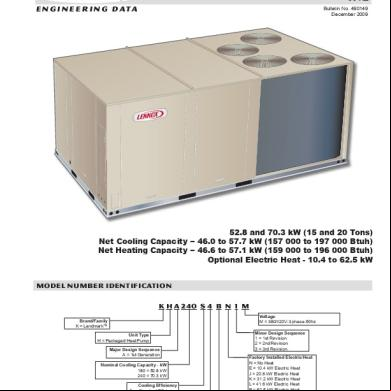
Lennox 6x6v5y
December 2019 55
Lennox Ms8 5m6n5y
December 2019 61
Buku Lennox 2lv4b
December 2019 39
Lennox Taa 414j5v
December 2019 40
Lennox Inverter.pdf 5o481h
December 2019 82
Lennox Hs29_3phase 2r1s
January 2022 0More Documents from "Charly Columb" 6n124o
Lennox 6x6v5y
December 2019 55
Agenda 1e584h
March 2023 0
Para Entrar Al De Joomla 4l1d6c
February 2023 0
Fundamentals Of Fixed Prosthodontics P 4355700 2s1l1f
October 2022 0
Kenny Barron Acorde Voicing Piano 6d694o
November 2020 0