Lennox Hs29_3phase 2r1s
This document was ed by and they confirmed that they have the permission to share it. If you are author or own the copyright of this book, please report to us by using this report form. Report 3b7i
Overview 3e4r5l
& View Lennox Hs29_3phase as PDF for free.
More details w3441
- Words: 6,045
- Pages: 20
AIR CONDITIONERS
HS29 SPLIT SYSTEM UNITS R−22 − 60 HZ ENGINEERING DATA
Bulletin No. 210307 June 2007 Supersedes October 2003
HS29−180, HS29−240
HS29−120
HS29−072, HS29−090
EER up to 10.5 6 to 20 Tons Cooling Capacity − 61,000 to 240,000 Btuh
MODEL NUMBER IDENTIFICATION
HS 29 − 120 − 1 Y Unit Type HS − High Side Air Conditioners Series Nominal Cooling Capacity 072 = 6 tons (21.1 kW) 090 = 7.5 tons (26.4 kW) 120 = 10 tons (35.2 kW) 180 = 15 tons (52.8 kW) 240 = 20 tons (70.3 kW)
Voltage Y = 208/230v−60hz−3ph G= 460v−60hz−3ph J = 575v−60hz−3ph Minor Revision Number
FEATURES AND BENEFITS
B
C J H
G
D
E
F
I HS29−180, HS29−240
HS29−120
HS29 6 to 20 Ton R−22 Air Conditioners / Page 2
HS29−072 (shown), HS29−090
FEATURES AND BENEFITS CONTENTS ARI Ratings . . . . . . . . . . . . . . . . . . . . . . . . . . . . . Page 8 Dimensions . . . . . . . . . . . . . . . . . . . . . . . . . Pages 10−12 Electrical Data . . . . . . . . . . . . . . . . . . . . . . . . Pages 6−7 Features and Benefits . . . . . . . . . . . . . . . . . Pages 2−4 Guide Specifications . . . . . . . . . . . . . . . . . Page 13 − 16 Unit Clearances . . . . . . . . . . . . . . . . . . . . . . . . . . Page 9 Model Number Identification . . . . . . . . . . . . . . . Page 1 Optional Accessories . . . . . . . . . . . . . . . . . . . Page 6−7 Optional Temperature Control Systems . . . . . Page 5 Sound Data . . . . . . . . . . . . . . . . . . . . . . . . . . . . . Page 7 Specifications . . . . . . . . . . . . . . . . . . . . . . . . . Pages 6−7 EQUIPMENT Warranty Compressor − limited warranty for five years in non−residential applications. All other covered components − one year in non−residential applications. Refer to Lennox Equipment Limited Warranty certificate for specific details. Approvals All units tested in Lennox Research Laboratory environmental test room. Air conditioners with a capacity of less than 65,000 Btuh are certified in accordance with the USE certification program, which is based on ARI Standard 210/240−2005. Air conditioners with a capacity of 65,000 Btuh or greater are certified in accordance with the ULE certification program, which is based on ARI Standard 340/360−2004. Sound tested in Lennox reverberant sound test room in accordance with test conditions included in ARI Standard 270-95 Units and components within are bonded for grounding to meet safety standards for servicing required by UL, ULC, NEC and CEC. All units are CSA listed. ISO 9001 ed Manufacturing Quality System. Applications Air conditioners are available in 6, 7.5, 10, 15 and 20 ton nominal sizes. Matching add−on furnace indoor coils or air handlers provide a wide range of cooling capacities and applications. See ARI Ratings tables. See Indoor Coils and Air Handlers tab sections for data. Units shipped completely factory assembled, piped, and wired. Each unit is test operated at the factory insuring proper operation. Installer must set air conditioner, connect refrigerant lines, and make electrical connections to complete job. For expanded ratings, see www.lennoxcommercial.com.
REFRIGERATION SYSTEM B Outdoor Coil Fan(s) HS29−072 and HS29−090 units have one outdoor fan. HS29−120 units have two outdoor fans. HS29−180 and HS29−240 units have four outdoor fans. Direct drive fan(s) moves large volumes of air uniformly through entire condenser coil(s) for high refrigerant cooling capacity. Upward discharge of air reduces operating sound levels and prevents damage to lawns, shrubs, and walkways. Fan motors are totally enclosed, inherently protected and equipped with a rain shield. Fan service access is accomplished by removal of fan guard(s). Copper Tube/Enhanced Fin Coil(s) C HS29−072 is equipped with a single L" shaped coil. HS29−090 is equipped with a single U" shaped coil. HS29−120 is equipped with two slab coils. HS29−180 and HS29−240 are equipped with four slab coils. Lennox designed and fabricated coils constructed of precisely spaced ripple-edge aluminum fins machine fitted to seamless copper tubes. Lanced fins provide maximum exposure of fin surface to air stream resulting in excellent heat transfer. Fins equipped with collars that grip tubing for maximum area. Flared shoulder tubing connections and silver soldering provide tight, leakproof ts. Long life copper tubing is corrosion-resistant and easy to field service. Thoroughly factory tested under high pressure to ensure leakproof construction. Completely accessible for cleaning. High Pressure Switch D Shuts off unit if abnormal operating conditions cause discharge pressure to rise above setting. Protects the compressor from excessive condensing pressure. Manual reset. Loss of Charge Switch E Shuts off unit if suction pressure falls below setting. Provides loss of charge and freeze-up protection. Automatic reset. Hi-Capacity Drier Furnished for field installation. Drier traps moisture or dirt that could contaminate the refrigerant system. F Refrigerant Lines and Service Valves Sweat connections. Fully serviceable liquid and suction line service valves provide complete service access to refrigerant system. Suction valve can be fully shut off, while liquid valve can be front seated to manage refrigerant charge while servicing system. OPTIONS
Hot Gas By Available for HS29−072, HS29−090, HS29−120 only. Hot gas by to suction contains hot gas by valve and de−superheating valve for reduced capacity control of condensing units. Hot gas by to evaporator contains hot gas by valve for reduced capacity control of condensing units.
HS29 6 to 20 Ton R−22 Air Conditioners / Page 3
FEATURES AND BENEFITS
G Compressors
HS29−072, HS29−090 and HS29−120 feature a single scroll compressor. HS29−180 and HS29−240 have two scroll compressors. Compressor features high efficiency with uniform suction flow, constant discharge flow and high volumetric efficiency and quiet operation. Compressor consists of two involute spiral scrolls matched together to generate a series of crescent shaped gas pockets between them. During compression, one scroll remains stationary while the other scroll orbits around it. Gas is drawn into the outer pocket, the pocket is sealed as the scroll rotates. As the spiral movement continues, gas pockets are pushed to the center of the scrolls. Volume between the pockets is simultaneously reduced. When pocket reaches the center, gas is now high pressure and is forced out of a port located in the center of the fixed scrolls. During compression, several pockets are compressed simultaneously resulting in a smooth continuous compression cycle. Continuous flank , maintained by centrifugal force, minimizes gas leakage and maximizes efficiency. Scroll compressor is tolerant to the effects of slugging and contaminants. If this occurs, scrolls separate, allowing liquid or contaminants to to be worked toward the center and discharged. Low gas pulses during compression reduces operational sound levels. Compressor motor is internally protected from excessive current and temperature. Compressor is installed in the unit on resilient rubber mounts for vibration free operation. Crankcase Heater(s) Assures proper compressor lubrication at all times. Cabinet H Heavy−gauge, pre−painted steel cabinet provides superior rust and corrosion protection. Removeable s allow access for unit servicing. I Heavy duty steel base channels raise the unit off of mounting surface away from damaging moisture. Unit lifting holes and forklift slots furnished in base rails. See dimension drawings. Control Box J Control box located in separate compartment in unit cabinet (−072, −090, −120 models). Hinged with quarter turn fastener for easy access. Slide out control box allows easy access to controls (180, 240 models). All controls are pre-wired at the factory. Coil Guard Corrosion resistant PVC (polyvinyl chloride) coated steel wire guard(s) furnished as standard. OPTIONS
Hail Guards Heavy duty sheet metal and metal mesh enclosures protect coils from damage. Field installed. See dimension drawings and Specifications table.
HS29 6 to 20 Ton R−22 Air Conditioners / Page 4
CONTROLS Minimum Run Time Control Prevents compressor short cycling and assures oil return to compressor. 5 minute minimum run time regardless of cooling demand. Low Ambient Operation Units will operate satisfactorily down to 0°F outdoor air temperature without any additional controls. OPTIONS
L Connection® Network Complete building automation control system for single or multi−zone applications. Options include local interface, software for local or remote communication, and hardware for networking other control functions. See L Connection Network Engineering Handbook Bulletin for details. Thermostat Thermostat is not furnished with unit and must be ordered extra. See Thermostat bulletins and Lennox Price Book.
OPTIONAL CONVENTIONAL TEMPERATURE CONTROL SYSTEMS − FIElD INSTALLED COMMERCIAL TOUCHSCREEN THERMOSTAT Intuitive Touchscreen Interface − Two Stage Heating / Two Stage Cooling Conventional or Heat Pump − Seven Day Programmable − Four Time Periods/Day − Economizer Output − Title 24 Compliant − ENERGY STAR® Qualified − Backlit Display − Automatic Changeover
C0STAT02AE1L
Sensors For Touchscreen Thermostat 1
Remote non−adjustable wall mount 20k temperature sensor . . . . . . . . . . . . . . . . . . . . . . . . . . . . . . .
C0SNZN01AE1−
1
Remote non−adjustable wall mount 10k averaging temperature sensor . . . . . . . . . . . . . . . . . . . . .
C0SNZN73AE1−
1
Remote non−adjustable duct mount temperature sensor . . . . . . . . . . . . . . . . . . . . . . . . . . . . . . . . . .
C0SNDC00AE1−
Outdoor temperature sensor . . . . . . . . . . . . . . . . . . . . . . . . . . . . . . . . . . . . . . . . . . . . . . . . . . . . . . . . . . .
C0SNSR03AE1−
Accessories For Touchscreen Thermostat Locking cover (clear) . . . . . . . . . . . . . . . . . . . . . . . . . . . . . . . . . . . . . . . . . . . . . . . . . . . . . . . . . . . . . . . . . .
C0MISC15AE1−
1 Remote
sensors for C0STAT02AE1L can be applied in the following combinations: (1) C0SNZN01AE1−, (2) C0SNZN73AE1−, (2) C0SNZN01AE1− and (1) C0SNZN73AE1−, (4) C0SNZN01AE1−, (3) C0SNZN01AE1− and (2) C0SNZN73AE1.
DIGITAL NON−PROGRAMMABLE THERMOSTATS Intuitive Interface − Automatic Changeover − Simple Up and Down Temperature Control Two−stage heating / cooling conventional systems . . . . . . . . . . . . . . . . . . . . . . . . . . . . . . . . . . . . . . .
C0STAT10AE1L
Sensor For Digital Non−Programmable Thermostats Above Remote wall mounted temperature sensor . . . . . . . . . . . . . . . . . . . . . . . . . . . . . . . . . . . . . . . . . . . . . . .
C0SNZN00AE1−
Intuitive Interface − Automatic Changeover − Backlit Display − Simple Up and Down Temperature Control One−stage heating / cooling conventional systems . . . . . . . . . . . . . . . . . . . . . . . . . . . . . . . . . . . . . . .
C0STAT12AE1L
Sensor For Digital Non−Programmable Thermostats Above Outdoor temperature sensor . . . . . . . . . . . . . . . . . . . . . . . . . . . . . . . . . . . . . . . . . . . . . . . . . . . . . . . . . . .
C0SNSR04AE1−
Accessories For Digital Non−Programmable Thermostats Above Optional wall mounting plate . . . . . . . . . . . . . . . . . . . . . . . . . . . . . . . . . . . . . . . . . . . . . . . . . . . . . . . . . . .
C0MISC17AE1−
HS29 6 to 20 Ton R−22 Air Conditioners / Page 5
Specifications
6 − 10 TON HS29−072
HS29−090
HS29−120
Nominal Size − Tons (kW)
6 (21.1)
7.5 (26.4)
10 (35.2)
Liquid line (o.d.) − in. (mm)
5/8 (15.9)
5/8 (15.9)
5/8 (15.9)
1−1/8 (28.6)
1−3/8 (34.9)
1−3/8 (34.9)
Model No.
General Data Connections (sweat)
Suction line (o.d.) − in. (mm)
Refrigerant Condenser Coil
dry air holding charge Net face area − sq. ft. (m2) Outer coil
12.92 (1.20)
22.50 (2.09)
29.36 (2.73) total
Inner coil
12.59 (1.17)
21.70 (2.02)
−−−
Tube diameter − in. (mm) & no. of rows
3/8 (9.5) − 2
3/8 (9.5) − 2
3/8 (9.5) − 2
20 (787)
20 (787)
20 (787)
(1) 24 (610) − 4
(1) 24 (610) − 4
(2) 24 (610) − 4
Motor hp (W)
(1) 1/2 (373)
(1) 3/4 (560)
(2) 1/2 (373)
cfm (L/s) total air volume
4500 (2125)
5150 (2430)
9760 (4605)
Rpm
1075
1060
1100
Watts
600
570
1100 total
319 (145)
405 (184)
557 (253)
Fins per inch (m) Condenser Fan(s)
Diameter − in. (mm) & no. of blades
Shipping
lbs. (kg) 1 package
ELECTRICAL DATA Line voltage data − 60 hz − 3 phase 208/230V 460V 575V 208/230V 460V 575V 208/230V 460V 575V 1 Maximum
Overcurrent Protection (amps)
40
20
15
60
35
25
90
40
30
circuit ampacity
27
13
11
40
21
16
54
25
18
No. of Compressors
1
1
1
1
1
1
1
1
1
Rated load amps (total)
18.6
9
7.4
28.8
14.7
10.8
37.8
17.2
12.4
Locked rotor amps (total)
156
75
54
195
95
80
239
125
80
No. of motors
1
1
1
1
1
1
2
2
2
Full load amps (total)
3
1.5
1.2
3.7
1.9
1.6
3.0 (6.0)
1.5 (3.0)
1.2 (2.4)
Locked rotor amps (total)
6
3
2.9
7.3
3.7
3.4
6.0 (12.0)
3.0 (6.0)
2.9 (5.8)
2 Minimum
Compressor
Condenser FanMotor (1 phase)
Optional Accessories − Must Be Ordered Extra Hail Guards
38M38
29M44
32M91
Hot Gas By Kit (by to suction)
48M59
48M57
48M55
Hot Gas By Kit (by to evaporator)
48M60
48M58
48M56
NOTE − Extremes of operating range are plus and minus 10% of line voltage. 1 HACR type circuit breaker or fuse. 2 Refer to National or Canadian Electrical Code manual to determine wire, fuse and disconnect size requirements.
HS29 6 to 20 Ton R−22 Air Conditioners / Page 6
Specifications
15 − 20 TON
General Data Connections (sweat)
Model No.
HS29−180
HS29−240
Nominal Size − Tons (kW)
15 (52.8)
20 (70.3)
Liquid line (o.d.) − in. (mm)
(2) 5/8 (15.9)
(2) 5/8 (15.9)
(2) 1−3/8 (34.9)
(2) 1−3/8 (34.9)
Suction line (o.d.) − in. (mm)
Refrigerant Condenser Coil
dry air holding charge Net face area − sq. ft. (m2)
58.68 (5.45)
58.68 (5.45)
Tube diameter − in. (mm) & no. of rows
3/8 (9.5) − 1
3/8 (9.5) − 2
20 (787)
15 (630)
(4) 24 (610) − 3
(4) 24 (610) − 3
(4) 1/3 (249)
(4) 1/3 (249)
16,000 (7550)
16,000 (7550)
Rpm
1075
1075
Watts
1500 total
1500 total
lbs. (kg) 1 package
998 (453)
1189 (539)
Fins per inch (m) Condenser Fan(s)
Diameter − in. (mm) & no. of blades Motor hp (W) cfm (L/s) total air volume
Shipping
ELECTRICAL DATA General Data
Line voltage data − 60 hz − 3 phase 1 Maximum
208/230V
460V
575V
208/230V
460V
575V
100
50
35
130
60
40
circuit ampacity
75
39
29
95
44
32
No. of Compressors
2
2
2
2
2
2
Rated load amps (total)
28.8 (57.6)
14.7 (29.4)
10.8 (21.6)
37.8 (75.6)
17.2 (34.4)
12.4 (24.8)
Locked rotor amps (total)
195 (390)
95 (190)
80 (160)
239 (478)
125 (250)
80 (160)
No. of motors
4
4
4
4
4
4
Full load amps (total)
2.4 (9.6)
1.3 (5.2)
1 (4)
2.4 (9.6)
1.3 (5.2)
1 (4)
Locked rotor amps (total)
4.7 (18.8)
2.4 (9.6)
1.9 (7.6)
4.7 (18.8)
2.4 (9.6)
1.9 (7.6)
Overcurrent Protection (amps) 2 Minimum
Compressor
Condenser FanMotor (1 phase)
Optional Accessories − Must Be Ordered Extra Hail Guards
79K91
79K91
NOTE − Extremes of operating range are plus and minus 10% of line voltage. 1 HACR type circuit breaker or fuse. 2 Refer to National or Canadian Electrical Code manual to determine wire, fuse and disconnect size requirements.
OUTDOOR SOUND DATA 1Sound
Octave Band Sound Power Levels dBA, re 10−12 Watts
1 Unit
63
125
250
500
1000
2000
4000
8000
Rating Number (dB)
HS29−072
N/A
77
77
76
75
71
65
58
86
HS29−090
N/A
73
77
77
75
72
66
57
87
HS29−120
N/A
N/A
N/A
N/A
N/A
N/A
N/A
N/A
90
HS29−180
N/A
92.5
91.5
90.5
89
87.5
81.5
75.5
N/A
HS29−240
N/A
N/A
N/A
N/A
N/A
N/A
N/A
N/A
N/A
Center Frequency − HZ
Model No.
NOTE − the octave sound power data does not include tonal correction. 1 Tested according to ARI Standard 270 test conditions.
HS29 6 to 20 Ton R−22 Air Conditioners / Page 7
ARI RATINGS 1
Gross Cooling Capacity Btuh
ARI Standard 210/240 or 340/360 Ratings
Cooling Capacity Btuh
Efficiency EER
SEER
Integrated Part load Value
Total Unit Watts
Indoor Unit Model No.
Expansion Device
HS29−072
6 TON
Up−Flow Indoor Coils 70,500
68,000
Indoor Coil 9.5
−−−
−−−
7160
Down−Flow Indoor Coils 63,000
61,000
26K35
Indoor Coil 9.0
10.5
−−−
6820
Horizontal Indoor Coils 68,000
C33−62D CR33−60D−F
26K35
Indoor Coil
65,000
9.3
−−−
−−−
7000
64,000
62,000
9.0
10.2
−−−
7020
CB29M−65 (Multi−Position)
Factory TXV
67,000
65,000
9.2
−−−
−−−
7040
CB30M−65 (Multi−Position)
Factory TXV
67,000
65,000
9.2
−−−
−−−
7070
CB30U−65 (Up−Flow)
Factory TXV
76,000
74,000
10.4
−−−
−−−
7190
CB17−95 (Up−Flow)
Factory TXV
76,000
74,000
10.4
−−−
−−−
7190
CBH17−95 (Horizontal)
Factory TXV
Air Handlers
CH23−68 Air Handler
HS29−090
7.5 TON
Up−Flow Indoor Coils 102,000
98,000
Indoor Coil 10.3
−−−
−−−
9520
Up−Flow Indoor Coils + Furnace 104,000
26K35
C17−090/120
Factory TXV
Indoor Coil + Furnace
101,000
10.5
−−−
−−−
9620
99,000
96,000
10.4
−−−
−−−
9320
CB17−95 (Up−Flow)
Factory TXV
99,000
96,000
10.4
−−−
−−−
9320
CBH17−95 (Horizontal)
Factory TXV
101,000
98,000
10.4
−−−
−−−
9420
CB17−135 (Up−Flow)
Factory TXV
101,000
98,000
10.4
−−−
−−−
9420
CBH17−135 (Horizontal)
Factory TXV
Air Handlers
C17−090/120 with G24−200 Air Handler
HS29−120
10 TON
Up−Flow Indoor Coils + Furnace 131,000
Factory TXV
Indoor Coil + Furnace
126,000
10.4
−−−
−−−
12,230
126,500
122,000
10.4
−−−
−−−
11,850
CB17−135 (Up−Flow)
Factory TXV
126,500
122,000
10.4
−−−
−−−
11,850
CBH17−135 (Horizontal)
Factory TXV
Air Handlers
C17−090/120 with G24−200
Factory TXV
Air Handler
HS29−180
15 TON
Air Handlers
Air Handler
180,000
174,000
10
−−−
11
18,320
(2) CB17−95 (Up−Flow)
Factory TXV
180,000
174,000
10
−−−
11
18,320
(2) CBH17−95 (Horizontal)
Factory TXV
182,000
176,000
10
−−−
10.8
17,960
CB17−185 (Up−Flow)
Factory TXV
182,000
176,000
10
−−−
10.8
17,960
CBH17−185 (Horizontal)
Factory TXV
HS29−240
20 TON
Air Handlers
Air Handler
239,000
232,000
9.6
−−−
10.7
24,170
(2) CB17−135 (Up−Flow)
Factory TXV
239,000
232,000
9.6
−−−
10.7
24,170
(2)CBH17−135 (Horizontal)
Factory TXV
247,000
240,000
10
−−−
10.8
24,490
CB17−275 (Up−Flow)
Factory TXV
247,000
240,000
10
−−−
10.8
24,490
CBH17−275 (Horizontal)
Factory TXV
NOTE − Net capacity includes indoor blower motor heat deduction. Gross capacity does not include indoor blower motor heat deduction. 1 Units with capacity less than 65,000 Btuh are certified in accordance with the USE certification program which is based on ARI Standard 210. Units with capacity of 65,000 Btuh or greater are certified in accordance with the ULE certification program which is based on ARI Standard 340/360: 95_F outdoor air temperature, 80_F db/67_F wb entering evaporator air (minimum external duct static pressure) with 25 ft. of connecting refrigerant lines.
HS29 6 to 20 Ton R−22 Air Conditioners / Page 8
UNIT CLEARANCES − INCHES (MM) HS29−072 AND HS29−090 36 (914)
36 (914) 1 36 (914)
NOTE − 48 inches (1219 mm) clearance required on top of unit. 1 NOTE − One side of coil may be 12 inches (305 mm).
1 36
(914)
HS29−120 1 36 (914)
36 (914)
36 (914)
NOTE − 48 inches (1219 mm) clearance required on top of unit. 1 NOTE − One side of coil may be 12 inches (305 mm).
1 36 (914)
HS29−180 AND HS29−240 36 (914)
1 36 (914)
1 36 (914)
48 (1219)
NOTE − 48 inches (1219 mm) clearance required on top of unit. 1 NOTE − One side of coil may be 12 inches (305 mm).
HS29 6 to 20 Ton R−22 Air Conditioners / Page 9
DIMENSIONS − HS29−072 & HS29−090 CORNER WEIGHT AA Model No. lbs. kg
CENTER OF GRAVITY BB lbs. kg
CC lbs. kg
DD lbs. kg
HS29−072
66
30
78
35
95
43
81
37
HS29−090
87
39
93
42
117
53
109
49
EE inch 22−3/4 23−7/8
Model No. HS29−072 HS29−090
EE
AA
BB
AA
EE
INLET AIR
BB
COMPRESSOR
COMPRESSOR
OUTDOOR COIL
INLET AIR
OUTDOOR COIL
FF
FF
CENTER OF GRAVITY
CENTER OF GRAVITY
OUTDOOR COIL
DD
OUTDOOR COIL
CC
INLET AIR
DD
CC INLET AIR
OPTIONAL HAIL GUARD (Field Installed All Coil Sides)
TOP VIEW
TOP VIEW
(HS29−072)
12 (305)
(HS29−090)
OPTIONAL HAIL GUARD (Field Installed All Coil Sides) 34 (864)
48 (1219) DISCHARGE AIR
CONTROL BOX CONTROL BOX ACCESS
ELECTRICAL INLETS (Either Side)
COMPRESSOR 3-1/2 (89)
2 (51)
2-1/4 (57) SUCTION LINE (Either Side)
A
B
10 (254) 11 11/16 (297)
49-3/4 (1264) LIFTING HOLES (For Rigging)
mm 406 400
OUTDOOR FAN AND GUARD
OUTDOOR FAN AND GUARD
INLET AIR
FF inch 16 15−3/4
mm 578 606
6-5/8 (168) 3-1/4 (83)
BASE
FORKLIFT SLOTS (Both Sides)
HOT GAS BY (Either Side)
35-3/4 (908)
LIQUID LINE (Either Side)
SERVICE VIEW
SIDE VIEW
Model No.
A
B
in.
mm
in.
mm
HS29−072
35
889
31−1/2
800
HS29−090
41−1/4
1048
37−3/4
959
HS29 6 to 20 Ton R−22 Air Conditioners / Page 10
BASE
DIMENSIONS − HS29−120 CORNER WEIGHT AA Model No. lbs. kg HS29−120
118
54
CENTER OF GRAVITY BB lbs. kg
CC lbs. kg
DD lbs. kg
161
161
118
73
73
Model No.
54
HS29−120
EE
FF
inch
mm
inch
mm
30-1/2
775
17−5/8
448
EE AA
BB OUTDOOR COIL
FF
CONTROL BOX OUTDOOR COIL
DD
CC INLET AIR OUTDOOR FANS AND GUARDS (2)
TOP VIEW
CENTER OF GRAVITY
OPTIONAL HAIL GUARD (Field Installed Both Sides)
OPTIONAL HAIL GUARD (Field Installed Both Sides)
70−3/4 (1797)
12 (305)
34 (864)
DISCHARGE AIR
CONTROL BOX ELECTRICAL INLETS (Either Side)
CONTROL BOX ACCESS COMPRESSOR
SUCTION LINE (Either Side)
49 (1245)
3−3/8 (86) 1−3/4 (44) 1−7/16 (37)
72 (1829) LIFTING HOLES (For Rigging)
SIDE VIEW
BASE FORKLIFT SLOTS (Both Sides)
4-3/8 (111) 6-5/8 (168) LIQUID LINE (Either Side)
3-1/4 (83)
35-3/4 (908)
BASE
SERVICE VIEW
HS29 6 to 20 Ton R−22 Air Conditioners / Page 11
DIMENSIONS − HS29−180 & HS29−240 CORNER WEIGHT AA Model No. lbs. kg
CENTER OF GRAVITY BB lbs. kg
CC lbs. kg
DD lbs. kg
Model No.
EE
FF
inch
mm
inch
mm
HS29−180
232
105
227
103
227
103
232
105
HS29−180
29−1/4
743
33−1/4
845
HS29−240
287
130
287
130
268
122
268
122
HS29−240
28−1/2
724
33−1/4
845
INLET AIR
SLIDE OUT CONTROL BOX
INLET AIR
BB
AA
OUTDOOR FANS AND GUARDS (4)
INLET AIR
INLET AIR
EE
FF CENTER OF GRAVITY
INLET AIR
DD
INLET AIR
ELECTRICAL INLETS (Either Side)
CC
INLET AIR REFRIGERANT LINE CONNECTIONS (flush with unit)
TOP VIEW
12 (373)
OPTIONAL HAIL GUARD (Field Installed Both Sides) 65 (1651) DISCHARGE AIR
INLET AIR
ACCESS
57-5/8 (1464)
ELECTRICAL INLETS (Either Side)
ACCESS
SLIDE OUT CONTROL BOX
INLET AIR COMPRESSORS (2)
49-7/8 (1267)
OUTDOOR COILS
8-1/4 (210)
3/4 (19)
11 (279)
14-3/8 (365) 3-3/8 (86)
11 (279)
REFRIGERANT LINE CONNECTIONS 66-3/4 (1695)
FRONT VIEW
HS29 6 to 20 Ton R−22 Air Conditioners / Page 12
8-1/4 (210)
14-3/8 (365) 3-3/8 (86)
3-1/4 (83) 3/4 (19)
59-3/8 (1508) LIFTING HOLES (For Rigging)
SIDE VIEW
GUIDE SPECIFICATIONS This Specification is for Lennox Industries outdoor Heat Pump (HP series) and Air Conditioners (HS series) units. Revise specification section number and title below to suit project requirements, specification practices and section content. Refer to CSI MasterFormat for other section numbers and titles. Optional text or text requiring a decision is indicated by bold brackets [ ]; delete text not required in final copy of specification. Specifier Notes typically precede specification text; delete notes in final copy of specification. Trade/brand names with appropriate symbols typically are used in Specifier Notes; symbols are not used in specification text. Metric conversion, where used, is soft metric conversion. SECTION 15670 REFRIGERANT CONDENSING UNITS PART 1 GENERAL 1.01 SUMMARY A.
Section Includes: Air Conditioners and Outdoor Unit Heat Pumps
Specifier Note: Revise paragraph below to suit project requirements. Add section numbers and titles per CSI MasterFormat and specifier’s practice. B.
Related Sections
Specifier Note: Article below may be omitted when specifying manufacturer’s proprietary products and recommended installation. Retain Reference Article when specifying products and installation by an industry reference standard. If retained, list standard(s) referenced in this section. Indicate issuing authority name, acronym, standard designation and title. Establish policy for indicating edition date of standard referenced. Conditions of the Contract or Division 1 References Section may establish the edition date of standards. This article does not require compliance with standard, but is merely a listing of references used. Article below should list only those industry standards referenced in this section. Retain only those reference standards to be used within the text of this Section. Add and delete as required for specific project. Specifier Note: ARI Standard 210/240 is only required for HS29 tonnages 3, 3.5, 4, 5 and 6 and HP29 tonnages 3, 3.5, 4 and 5. ARI Standard 340/360 is only required for HS29 tonnages 7.5, 10, 15 and 20 and HP29 tonnages 7.5 and 10. 1.02 REFERENCES A.
B.
C. D.
Air−Conditioning and Refrigeration Institute (ARI): 1. ARI Standard 210/240 for Unitary Air−Conditioning and Air−Source Heat Pump Equipment (if applicable). 2. ARI 270−95 Sound Rating of Outdoor Unitary Equipment. 3. ARI 340/360 Commercial and Industrial Unitary Air−Conditioning and Heat Pump Equipment (ANSI approved)(if applicable). Servicing Standards: 1. National Electric Code (NEC). 2. Underwriters Laboratories (UL). 3. Canadian Electric Code (CEC). Department of Energy (DOE), units rated to ISO 9001, units manufactured to quality standard
Specifier Note: Article below should be restricted to statements describing design or performance requirements and functional (not dimensional) tolerances of a complete system. Limit descriptions to composite and operational properties required to link components of a system together and to interface with other systems. 1.03 SYSTEM DESCRIPTION A.
Performance Requirements: 1. [Heat Pumps: 3, 3.5, 4, 5, 7.5 and 10 ton capacity]. 2. [Air Conditioners: 3, 3.5, 4, 5, 6, 7.5, 10, 15 and 20 ton capacity]. 3. Electrical Characteristics: a. 60 Hz. b. 3 phase.
Specifier Note: The 575 V option below is only available on the HS29 tonnages of 6, 7.5, 10, 15, 20 and on the HP29 Tonnages of 7.5 and 10. c. [208/230 V] [460 V] [575 V]. Specifier Note: Article below includes submittal of relevant data to be furnished by Contractor before, during or after construction. Coordinate this article with Architect’s and Contractor’s duties and responsibilities in Conditions of the Contract and Division 1 Submittal Procedures Section.
HS29 6 to 20 Ton R−22 Air Conditioners / Page 13
GUIDE SPECIFICATIONS 1.04 SUBMITTALS A. B. C.
D.
General: Submit listed submittals in accordance with Conditions of the Contract and Division 1 Submittal Procedures. Product Data: Submit product data, including manufacturer’s SPEC−DATA® product sheet, for specified products. Shop Drawings: 1. Submit shop drawings in accordance with Section [01330 − Submittal Procedures]. 2. Indicate: a. Equipment, piping and connections, together with valves, strainers, control assemblies, thermostatic controls, auxiliaries and hardware and recommended ancillaries which are mounted, wired and piped ready for final connection to building system, its size and recommended by connections. b. Piping, valves and fittings shipped loose showing final location in assembly. c. Control equipment shipped loose, showing final location in assembly. d. Field wiring diagrams. e. Dimensions, internal and external construction details, installation clearances, recommended method of installation, sizes and location of mounting boltholes. f. Detailed composite wiring diagrams for control systems showing factory installed wiring and equipment on packaged equipment or required for controlling devices or ancillaries, accessories, controllers. Quality Assurance: 1. All units to be factory tested before shipping. 2. Manufacturer’s Instructions: Manufacturer’s installation instructions.
Specifier Note: Coordinate paragraph below with Part 3 Field Quality Requirements Article herein. Retain or delete as applicable. E.
Closeout Submittals: Submit the following: 1. Warranty: Warranty documents specified herein. 2. Operation and Maintenance Data: Operation and maintenance data for installed products in accordance with Division 1 Closeout Submittals (Maintenance Data and Operation Data) Section. Include methods for maintaining installed products and precautions against cleaning materials and methods detrimental to finishes and performance. Include names and addresses of spare part suppliers. 3. Provide brief description of unit, with details of function, operation, control and component service. 4. Commissioning Report: Submit commissioning reports, report forms and schematics in accordance with Section 01810 − Commissioning.
1.05 QUALITY ASSURANCE A.
B.
Qualifications: 1. Installer experienced in performing work of this section who has specialized in installation of work similar to that required for this project. 2. Manufacturer Qualifications: Manufacturer capable of providing field service representation during construction and approving application method. Pre−installation Meetings: Conduct pre−installation meeting to project requirements, manufacturer’s installation instructions and manufacturer’s warranty requirements. Comply with Division 1 Project Management and Coordination (Project Meetings).
1.06 DELIVERY, STORAGE & HANDLING A. B. C.
D.
General: Comply with Division 1 Product Requirements. Ordering: Comply with manufacturer’s ordering instructions and lead−time requirements to avoid construction delays. Packing, Shipping, Handling and Delivery: 1. Deliver materials in manufacturer’s original, unopened, undamaged containers with identification labels intact. 2. Ship, handle and unload units according to manufacturer’s instructions. Storage and Protection: 1. Store materials protected from exposure to harmful weather conditions. 2. Factory shipping covers to remain in place until installation.
Specifier Note: Coordinate article below with Conditions of the Contract and with Division 1 Closeout Submittals (Warranty). 1.07 WARRANTY A. B.
Project Warranty: Refer to Conditions of the Contract for project warranty provisions. Manufacturer’s Warranty: Submit, for Owner’s acceptance, manufacturer’s standard warranty document executed by authorized company official. Manufacturer’s warranty is in addition to, and not a limitation of, other rights Owner may have under Contract Documents.
Specifier Note: Coordinate paragraph below with manufacturer’s warranty requirements. C.
Warranty: Commencing on Date of Installation. 1. Compressor: 5 year limited (nonresidential applications). 2. Other Covered Components: 1 year limited (nonresidential applications).
HS29 6 to 20 Ton R−22 Air Conditioners / Page 14
GUIDE SPECIFICATIONS PART 2 PRODUCTS Specifier Note: Retain article below for proprietary method specification. Add product attributes, performance characteristics, material standards and descriptions as applicable. Use of such phrases as or equal" or or approved equal" or similar phrases may cause ambiguity in specifications. Such phrases require verification (procedural, legal and regulatory) and assignment of responsibility for determining or equal" products. 2.01 AIR CONDITIONERS/OUTDOOR UNIT HEAT PUMPS A. B.
Manufacturer: Lennox Industries. 1. : 2100 Lake Park Blvd., Richardson, TX 75080; Telephone: (800) 453−6669; Web site: www.lennox.com. Proprietary Products/Systems: HP29 Series, HS29 Series, including the following equipment: 1. Cabinet: a. Galvanized steel b. Pre−painted finish.
Specifier Note: Control box, for HS29 tonnages of 6, 7.5, 10 and HP tonnages of 7.5 and 10, is located in a separate compartment for easy access. Control box, for HS29 tonnages of 15 and 20, is a slide out type for easy access.
2.
c. Openings, or control box, for refrigerant lines and power connection entry. d. Control Access. e. All controls factory wired Compressor: a. Scroll Type b. Resiliently mounted on rubber mounts for vibration isolation c. Overload protected d. Internal excessive current and temperature protection.
Specifier Note: Crankcase heater is an option for the HP29 tonnages of 3, 3.5, 4 and 5. e. Crankcase heater Specifier Note: HS29 tonnages of 3, 4, 5, 6, 7.5 and 120 and HP29 tonnages of 3, 4 and 5 use 1 single speed scroll compressor. HS29 Tonnages 15 and 20 use 2 single speed scroll compressors.
3.
f. 1 or 2 single speed compressor(s) per unit. Refrigerant System
Specifier Note: General below refers to all HS29 tonnages and HP29 tonnages. a. General 1. Refrigerant: R22 2. Fully serviceable liquid and suction line service valves. 3. Gauge ports. Specifier Note: Refrigerant System (small) below refers to HP29 tonnages of 3, 4 and 5 only. b. Refrigerant System (small): 1. [Reversing valve and defrost/time−off control (HP29 models only)] Specifier Note: Refrigerant System (large) below refers to HS29 tonnages of 6, 7.5, 10, 15 and 20 and HP29 tonnages of 7.5 and 10. c. Refrigerant System (large): 1. High pressure switch 2. Loss of charge (low pressure) switch 3. Minimum run time control. 4. [Field installed hi−capacity driers (HS29 models only)] 5. [Reversing valve and defrost/time−off control (HP29 models only)] 6. [Factory installed hi−capacity driers (HP29 models only)]
HS29 6 to 20 Ton R−22 Air Conditioners / Page 15
GUIDE SPECIFICATIONS Specifier Note: Include following sentence for HP models. 4.
5.
6.
Outdoor Coil(s): a. Aluminum rippled and lanced fins. b. Copper tube construction. c. Aluminum fins to be mechanically bonded to copper tubes. d. All coils to be high pressure leak tested at factory. Outdoor Coil Fans/Air Mover: a. Direct drive, propeller type fan(s). b. Totally enclosed fan motors. c. Steel fan guards or louvered steel fan guard. d. Fan service by removal of fan guard. [Accessories]:
Specifier Note: Field installed (small) below refers to HS29 tonnages of 3, 4, 5 and HP29 tonnages of 3, 4 and 5. a. [Field installed (small):] 1. 2.
[Hail Guards: Louvered, heavy gauge steel. ] [Mounting base capable of withstanding effects of sun, heat, cold, moisture, oil and refrigerant.] 3. [Unit stand−off kit to raise unit off mounting surface. 4. [Compressor low ambient cut out] 5. [Reinforced vinyl compressor cover, 1−1/2" thick fiberglass insulation.] 6. [Freezestat] 7. [Low Ambient Kit] 8. [Thermostat] 9. [Loss of charge kit] 10. [Monitor Kit] 11. [Outdoor thermostat kit (HP29 models only)] 12. [Mild ambient kit (HP29 models only)] Specifier Note: Field installed (large) below refers to HS29 tonnages of 6, 7.5, 10, 15 and 20 and HP29 tonnages of 7.5 and 10. b. [Field installed (large):] 1. [Hail Guards] 2. [Hot gas by.] 3. [Thermostat] 2.02 PRODUCT SUBSTITUTIONS A. Substitutions: No substitutions permitted. PART 3 EXECUTION 3.01 MANUFACTURER’S INSTRUCTIONS Specifier Note: Revise article below to suit project requirements and specifier’s practice. A.
Compliance: Comply with manufacturer’s written data, including product technical bulletins, product catastallation instructions and product carton installation instructions. 3.02 EXAMINATION A. Site Verification of Conditions: substrate conditions, which have been previously installed under other sections, are acceptable for product installation in accordance with manufacturer’s instructions. 3.03 INSTALLATION A. Install Air Conditioners and/or Heat pumps in accordance with manufacturers instructions and regulations of authorities having jurisdiction. END OF SECTION
HS29 6 to 20 Ton R−22 Air Conditioners / Page 16
Visit us at www.lennox.com For the latest technical information, www.lennoxcommercial.com us at 1−800−4−LENNOX
NOTE − Due to Lennox’ ongoing committment to quality, Specifications, Ratings and Dimensions subject to change without notice and without incurring liability. Improper installation, adjustment, alteration, service or maintenance can cause property damage or personal injury. ©2007 Lennox Industries Inc. Installation and service must be performed by a qualified installer and servicing agency.
Related Documents 3m3m1z
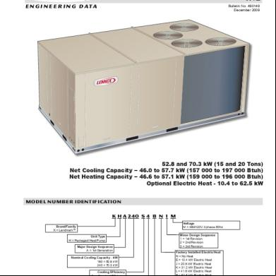
Lennox 6x6v5y
December 2019 55
Lennox Ms8 5m6n5y
December 2019 61
Buku Lennox 2lv4b
December 2019 39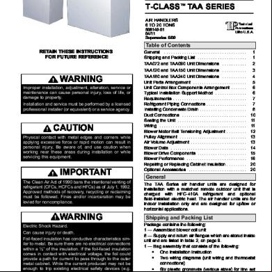
Lennox Taa 414j5v
December 2019 40
Lennox Inverter.pdf 5o481h
December 2019 82