This document was ed by and they confirmed that they have the permission to share it. If you are author or own the copyright of this book, please report to us by using this report form. Report 3b7i
Overview 3e4r5l
& View Moments & Reactions For Rectangular Plates (moody's Chart).pdf as PDF for free.
More details w3441
- Words: 14,800
- Pages:
.
A
WATER
RESOURCES
TECHNICAL
ENGINEERING MONOGRAPH
PUBLICATION
NO.
27
Moments and Reactions for Rectangular Plates UNITED STATES DEPARTMENT OF THE INTERIOR BUREAU
OF
RECLAMATION
A
WATER
Engineering
RESOURCES TECHNICAL
Monograph
PUBLICATION
NO. P7
Moments and Reactions for Rectangular Plates By W. T. MOODY Division of Design Denver, Colorado
United
States
Department
of the Interior
BUREAU OF RECLAMATION
As the Nation’s principal conservation agency, the Department of the Interior has responsibility for most of our nationally owned public lands and natural resources. This includes fostering the wisest use of our land and water resources, protecting our fish and wildlife, preserving the environmental and cultural values of our national parks and historical places, and providing for the enjoyment of life through outdoor recreation. The Department assesses our energy and mineral resources and works to assure that their development is in the best interests of all our people. The Department also has a major responsibility for American Indian reservation communities and for people who live in Island Territories under U.S. istration.
First Printing: October 1963 Revised: July 1963 Reprinted: April 1966 Reprinted: July 1970 Reprinted: June 1975 Reprinted: December 1976 Reprinted: January 1978 Reprinted: April 1980 Reprinted: March 1983 Reprinted: June 1986 Reprinted: August 1990
U.S. GOVERNMENT PRINTING WASHINGTON : 1978
OFFICE
Preface presents a series of tables containing computed data for use in the design of components of structures which can be idealized as rectangular plates or slabs. Typical examples are wall and footing s of counterfort retaining walls. The tables provide the designer with a rapid and economical means of analyzing the The data structures at representative points. presented, as indicated in the accompanying figure on the frontispiece, were computed for fivl: sets of boundary conditions, nine ratios of lateral dimensions, and eleven loadings typical of those encountered in design. THIS
MONOGRAPH
As supplementary guides to the use and development of the data compiled in this monograph, two appendixes are included. The first appendix presents an example of application of the data to a typical structure. The second appendix explains the basic mathematical considerations and develops the application of the finite difference method to the solution of plate problems. A series of drawings in the appendixes presents basic relations which will aid in application of the method to other problems. Other drawings illustrate application of the method to one of the specific cases and lateral dimension ratios included in the monograph.
Acknowledgments The writer was assisted in the numerical computations by W. S. Young, J. R. Brizzolara, and D. Misterek. H. J. Kahm assisted in the computations and in checking the results obtained.
The figures were prepared by H. E. Willmann. Solutions of the simultaneous equations were performed using an electronic calculator under the direction of F. E. Swain.
CASE
I
CASE
2
CASE
3
CASE
4
CASE
5
PLATE FIXED FOVR EOBES
BOUNDARY
CONOITIONS
0f------IL!kl
L-p-A LOAD
LOAD
I
id- pd
n
LOAD
“NWORY LOAD OVER e/3 THE “EIBHT OF THE PLITE
IU
LOAD
Ip
;pd
LOAD
“WlFORYLI “ARIINO LOAD OVER THE FVLL HEIGHT OF THE PLATE
“NlFORY LOAD OVER 113 THE HEIOHT OF THE PLATE
f---G i-d
H
LOAD
PII
LOAD
Pm
LOAD
UNIFORM YOYEW ALOW IHE soce y - b FOR OASES I, L. AND 5
“NlFORYL” “AWlNO LOAD OVER l/6 THE “ElB”f OF T”E PLATE
iI
UNIFORM LINE LOAD ILOWOWE FREEEOBE FOR OASES I AND 3
fP 7-P-q k-----a----+ LOAD
H
“WIFORYLI “ARIIYB LOAD p - 0 ALON0 x - a,*
LOADING
CONDITIONS
NOTES The variaus cases ratios of o/b. Coses I, e, and 3:
Cose
4
Case 5 All results
INDEX
: :
are
are
analyzed
I/B,
3/a, I, ond 3/z. 314, and I. 3/4, 7/e, ond I. on a Poisson’s ratio of 0.2.
l/8, 310,
bored
OF BOUNDARY
for
1f4,
3/s,
I/Z,
l/4, I/S?,
3/0, s/8,
I/2,
AND
the indicated
LOADING
-FRONTISPIECE
CONDITIONS
Y
“NlFORYLl “ARIINO LOAD OVER e/3 TM ns,en* OF THE PLATE
-H LOAD
*Lowe
LOAD
p LI
“WIFORYL” “m”I*e D- o ALOWOy-b/e
LOAD
Contents Preface
and Acknowledgments
-----____-___________--__
Frontispiece
__------________________________________---------
Introduction
________________________.______ - _________________
Method
of Analysis
Page .. . ill
iv 1
______________________________ -- ______
3
Results ________________________________________-------- ______
5
Effect of Poisson’s Ratio- ___________________________- ________
Accuracy Appendix
of Method of Analysis--------------------I ______________________________ - _________________
An Application to a Design Problem-- - - ___________- ___ ________
Appendix
6 43 45 45
I I ________________________________________________
49
The Finite Difference Method- _ _ _ _________________________- _Introduction____________________________---------------General Mathematical Relations- _ ____-__ ______________-_ _ Application to Plate Fixed Along Three Edges and Free Along the Fourth__________________________________---------
49 49 49
List of ,Re f erences------------------------------------_____ LIST
OF
54 89
FIGURES
Number
PW
1. Plate fixed along three edges, moment and reaction coefficients, Load
I, uniform load- ----------------->---------_-------------2. Plate fixed along three edges, moment and reaction coefficients, Load II, 213 uniform load _____________ ___________________________ 3. Plate fixed along three edges, moment and reaction coefficients, Load III, l/3 uniform load--------______________________________ 4. Plate fixed along three edges, moment and reaction coefficients, Load IV, uniformly varying load _________________________________ _
7 8 9 10 V
CONTENTS
vi Number
5. Plate fixed along three edges, moment and reaction coefficients, Load V, 213 uniformly varyingload _---__--_______ ------________ 6. Plate fixed along three edges, moment and reaction coefficients, Load VI, l/3 uniformly varying load -------____________________ 7. Plate fixed along three edges, moment and reaction coefficients, Load VII, l/6 uniformly varyingload--_-----..-----______________ 8. Plate fixed along three edges, moment and reaction coefficients, Load VIII, moment at free edge------_____ ---------____________ 9. Plate fixed along three edges, moment and reaction coefficients, Load IX, lineload at free edge---------------------_____________ 10. Plate fixed along three edges-Hinged along one edge, moment and reaction coefficients, Load I, uniform load---- - - - _ - __ _ _ __ _ __ _ __ 11. Plate fixed along three edges-Hinged along one edge, moment and reaction coefficients, Load II, 213 uniform load_ - _ __ __ _ _ __ _ _ __ _ 12. Plate fixed along three edges-Hinged along one edge, moment and reaction coefficients, Load III, l/3 uniform load- - - - __ __ _ __ _ _ _ 13. Plate fixed along three edges-Hinged along one edge, moment and reaction coefficients, Load IV, uniformly varying load - _ __ _ __ _ __ 14. Plate fixed along three edges-Hinged along one edge, moment and reaction coefficients, Load V, 213 uniformly varying load--_ __ _ __ 15. Plate fixed along three edges-Hinged along one edge, moment and reaction coefficients, Load VI, l/3 uniformly varying load_- _ __ _ _ 16. Plate fixed along three edges-Hinged along one edge, moment and reaction coefficients, Load VII, l/6 uniformly varying load- __ _ _ _ 17. Plate fixed along three edges-Hinged along one edge, moment and reaction coefficients, Load VIII, moment at hinged edge- - - - - - _ _ 18. Plate fixed along one edge-Hinged along two opposite edges, moment and reaction coefficients, Load I, uniform load--- __ _ _ __ _ _ 19. Plate fixed along one edge-Hinged along two opposite edges, moment and react,ion coefficients, Load II, 213 uniform load _ _ _ _ __ _ 20. Plate fixed along one edge-Hinged along two opposite edges, moment and reaction coefficients, Load III, l/3 uniform load- _- _ _ 21. Plate fixed along one edge-Hinged along two opposite edges, moment and reaction coefficients, Load IV, uniformly varying load. 22. Plate fixed along one edge-Hinged along two opposite edges, moment and reaction coefficients, Load V, 213 uniformly varying load----_______-----____________________-----------------23. Plate fixed along one edge-Hinged along two opposite edges, moment and reaction coefficients, Load VI, l/3 uniformly varying load_-__-------_________________________-----------------24. Plate fixed along one edge-Hinged along two opposite edges, moment and reaction coefficients, Load VII, l/6 uniformly varying load- ---__-_-_-----__------~~~~~~~~--~~-----------------25. Plate fixed along one edge-Hinged along two opposite edges, moment and reaction coefficients, Load VIII, moment at free edge- 26. Plate fixed along one edge-Hinged along two opposite edges, moment and reaction coefficients, Load IX, line load at free edge27. Plate fixed along two adjacent edges, moment and reaction coefllcients, Load I, uniform load--- __________- ------------------
me 11 12 13 14 15 16 17 18 19 20 21 22 23 24 25 26 27
28
29
30 31 32 33
CONTENTS Number
28. Plate fixed along two adjacent edges, moment and reaction coefficients, Load II, 213 uniform load------------______________ 29. Plate fixed along two adjacent edges, moment and reaction coefficients, Load III, l/3 uniform load- _ - - - - - - - _ __ _ __ _ __ _ _ _ __ _ __ 30. Plate fixed along two adjacent edges, moment and reaction coefficients, Load IV, uniformly varying load- - _- - _ - - - - _ _ _ _ __ _ ___ _ 31. Plate fixed along two adjacent edges, moment and reaction coefficients, Load V, 2/3 uniformly varying load- _- - - - - - - _ _ _ __ _ __ _ _ 32. Plate fixed along two adjacent edges, moment and reaction coefficients, Load VI, l/3 uniformly varying load- _- - - - _ __ _ _ __ _ _ __ _ 33. Plate fixed along two adjacent edges, moment and reaction coefficients, Load VII, l/6 uniformly varying load-- _ _ __ _ _ __ _ _ __ _ __ 34. Plate fixed along four edges, moment and reaction coefficients, Load I,uniformload____-----------_____________________-------35. Plate fixed along four edges, moment and reaction coefficients, Load X, uniformly varying load, p=O along y=b/2------__________ 36. Plate fixed along four edges, moment and reaction coefficients, Load XI, uniformly varying load, p=O along x=a/2---------------.. 37. Counterfort wall, design example---~---------------~-~~~~~-~..~ 38. Grid point designation system and notation_- - - _- _ - - _ _ __ _ __ _ _ _ 39. Load-deflection relations, Sheet I _______________ --__--_-------40. Load-deflection relations, Sheet II----------------------------41. Load-deflection relations, Sheet III---------------------------42. Load-deflection relations, Sheet IV __________ -___--_-------_---43. Load-deflection relations, vertical spacing: 3 at h; 1 at h/2, Sheet V44. Load-deflection relations, vertical spacing: 2 at h; 2 at h/2, Sheet VI45. Load-deflection relations, vertical spacing: 2 at h; 1 at h/2; 1 at h/4, SheetVII___-_-----______________________----------------46. Load-deflection relations, vertical spacing: 1 at h; 3 at h/2, Sheet VIII--__-----_-_----------------------------------------47. Load-deflection relations, vertical spacing: 1 at h; 1 at h/2; 2 at h/4, SheetIX___-_________-_-______________________----------48. Load-deflection relations, vertical spacing: 1 each at h, h/2, h/4, and h/8, Sheet X------------_____________________________ 49. Load-deflection relations, vertical spacing: 4 at h/2, Sheet Xl _ _ _ _ _ 50. Load-deflection relations, vertical spacing: 1 at h/2; 3 at h/4, Sheet XII---------------------------------------------------51. Load-deflection relations, vertical spacing: 1 at h/2 ; 1 at h/4; 2 at h/8, Sheet XIII--------------_______-_____________________ 52. Load-deflection relations, vertical spacing: 4 at h/4, Sheet XIV--- 53. Load-deflection relations, vertical spacing: 1 at h/4; 3 at h/8, Sheet xv ____ ------------------------------------------------54. Load-deflection relations, vertical spacing: 4 at h/8, Sheet XVI---55. Load-deflection relations, horizontal spacing: 4 at rh/2, Sheet XVII56. Load-deflection relations, horizontal spacing: 3 at rh/2; 1 at rh, SheetXVIII_-------_------------------------------------57. Load-deflection relations, horizontal spacing: 2 at rh/2; 2 at rh, SheetXIX _______________________ --- _________ -_-_-_- ______ 58. Load-deflection relations, horizontal spacing: 1 at rh/2 ; 3 at rh, Sheet xX-__-_------_--_--________________________________
vii page
34 35 36 37 38 39 40 41 42 46 50 56 57 58 59 60 61 62 63 64 6.5 66 67 68 69 70 71 72 73 74 75
CONTENTS
Viii Number
PW
59. Load-deflection relations, horizontal spacing: 4 at rh, Sheet XXI- _ 60. Moment-deflectionrelations--______________--_--___-- ________ 61. Moment-deflection relations, various point spacings- _____________ 62. Shear-deflection relations, Sheet I--- __- - - - __- - - ________________ 63. Shear-deflection relations, Sheet II-------------____- __________ 64. Shear-deflection relations, Sheet III- ___________________________ 65. Load-deflection coefficients, r=1/4, p=O.2------____ -- _________ 66. Plate fixed along three edges-30 equations for determining unknown deflections. a/b=114 _______________--______ --- ____--- _____ 67. Plate fixed along three edges, deflection coefficients. a/b=114 Variousloadings________--_---____________---___----_______ 68. Plate fixed along three edges-20 equations for determining unknown deflections. a/b=114 _______________________---___---- _____ 69. Numerical values of typical moment and reaction arrays, r=1/4, p=o.2 __-____-___-------______________________------------
70. Plate fixed along three edges, deflections-reactions-bending ____ ----- _______ moments,Load I. a/b=1/4, p=O.2-----------
76 77 78 79 80 81 82 83 84 85 86 87
LIST OF TABLES NUmb6T
2.
3. 4. 5. 6.
Bending Moment at the Center of a Uniformly Loaded Rectangular Plate Fixed along Four Edges _______--_-___-___----_-----_____--Comparison of Coefficients of Maximum Bending Moment at the Center of a Uniformly Loaded Rectangular Plate Fixed along FourEdges____________--________-____________________-____ M, for Heel Slab at s------- ________--- _____-_---- ______ M, for Heel Slab at s- ____-- ______--__- _________-- ______ M,forWallSlabats ____ -- _-____________________- _____ M, for Wall Slab at s- __ _______________________________
Pap
1. Effect of Poisson’s Ratio (p) on Coefficients of Maximum
6 43 47 47 48 48
Introduction CERTAIN COMPONENTS of many structures may be logically idealized as laterally loaded, rectangular plates or slabs having various conditions of edge . This monograph presents tables of coefficients which can be used to determine moments and reactions in such structures for various loading conditions ,and for several ratios of lateral dimensions. The finite difference method was used in the analysis of the structures and in the development of the tables. This method, described in Appendix
II of this monograph, makes possible the analysis of rectangular plates for any of the usual types of edge conditions, and in addition it can readily take into virtually all types of loading. An inherent disadvantage of the method lies in the great amount of work required in solution of the large number of simultaneous equations to which it gives rise. However, such equations can be readily systematized and solved by an electronic calculator, thus largely offsetting this disadvantage.
Method
of Analysis
FINITE difference method is based on t,he usual approximate theory for the bending of thin plates subjected to lateral loads.‘* The customary assumptions are made, therefore, with regard to homogeneity, isotropy, conformance with Hooke’s law, and relative magnitudes of deflections, thickness, and lateral dimensions. (See Appendix II.) Solution by finite differences provides a means of determining a set of deflections for discrete points of a plate subjected to given loading and The deflections are determined edge conditions. in such a manner that the deflection of any point, together with those of certain nearby points, satisfy finite difference relations which correspond to the differential expressions of the usual plate theory. These expressions relate coordinates and deflections to load and edge conditions. THE
*Numbers page 89.
in superscript
refer to publications
in List of References
on
In this study, for each load and ratio of lateral dimensions, deflections were determined at 30 or more grid points by solution of an equal number of simultaneous equations. A relatively closer spacing of points was used in some instances near fixed boundaries t’o attain the desired accuracy in this region of high curvature. For the a/b ratios l/4 and l/8, one and two additional sets, respectively, of five deflections were determmed in the vicinity of the x axis. Owing to the limitations on computer capacity, these deflections were computed by solutions of supplementary sets of 20 equations whose right-hand were functions of certain of the initially computed deflections as well as of the loads. In each case, the solution of the equations was made through the use of an electronic calculator. Computations of moments and reactions were made using desk calculators and the appropriate finite difference relations. The finite difference relations used are discussed in Appendix II.
FIGURES 1 through 36 present the results of these studies as tables of dimensionless coefficients for the rectangular components of bending moment and for reactions at the s. The studies were carried out for the following edge, or boundary, conditions : Case 1: Plate fixed along three edges and free along the fourth edge. Case 2: Plate fixed along three edges and hinged along the fourth edge. Case 3: Plate fixed along one edge, free along the opposite edge, and hinged along the other two edges. Case 4: Plate fixed along two adjacent edges and free along the other two edges. Case 5: Plate fixed along four edges. The loads, selected because they are representative of conditions frequently’ ‘encountered in structures, are : Load I: Uniform load over the full height of the plate. Load II: Uniform load over 2/3 the height of the plate. Load III: Uniform load over l/3 the height of the plate. Load IV: Uniformly varying load over the full height of the plate.
Load V: Uniformly varying load over 213 the height of the plate. Load VI: Uniformly varying load over l/3 the height of the plate. Load VII : Uniformly varying load over l/6 the height of the plate. Load VIII: Uniform moment along the edge y=b of the plate for Cases 1, 2, and 3. Load IX: Uniform line load along the free edge of the plate for Cases 1 and 3. Load X: Uniformly varying load, p=O along y=b/2. Load XI : Uniformly varying load, p = 0 along x=a/2. Plates with the following ratios of lateral dimensions, a, to height b, were studied for the first four cases: l/8, l/4, 318, l/2, 314, 1, 312. The analysis was carried out for these cases using Loads I through IX and all dimension ratios, except that Load IX was omitted from Case 2 for obvious reasons, and Loads VIII and IX and the ratio a/b=312 were omitted from Case 4. It will be noted that for the first three cases, which have symmetry about a vertical axis, the dimension a denotes one-half of the plate width, and for the fourth, unsymmetrical case, a denotes the full width. For Case 5, lateral 5
MOMENTS AND REACTIONS FOR RECTANGULAR PLATES
6
dimension ratios of 318, l/2, 518, 3/4, 718 and 1 were studied, subjected to Loads I, X, and XI. For this case, a and b denote the full lateral dimensions. All numerical results are based on a value of Poisson’s ratio of 0.2. The arrangement of the tables is such t,hat each coefficient, both for reaction and moment, appears in the tables at a point which corresponds geometrically to its location in the plate as shown in each accompanying sketch. Effect of Poisson’s
can be determined easily, since the deflections computed from finite difference theory are independent of Poisson’s ratio. Futhermore, the bending moments at, and normal to, the fixed edges are unaffected by this factor. It is reasonable then to conclude that insofar as the moments which are most important in design are concerned, the maximum effect for this case will occur at the center of the slab. Table 1 shows a comparison of maximum bending moment coeflicients at the center of a uniformly loaded plate for several values of p and for each ratio of a/b for which Case 5 was computed. For a change in Poisson’s ratio from 0.2 to 0.3 it is noted that the maximum effect on the bending moment coefficient occurs at a/b= 1, where the change in the coefficient is less than 8 percent.
Ratio
A question which frequently arises is: What effect does Poisson’s ratio have on the bending moments in a plate? For the plate fixed along four sides, a clear understanding of this effect TABLE
l.-Effect
of Poisson’s
Ratio (p) on Coeficienk of Maximum Bending Moment Loaded Rectangular Plate Fixed Along Four Edges
-% “;I 0. 375 0. 5 0.625 0. 75 0. 875 1. 0
at the Center
Values of M./pa* 0
0.1
0.2
0.3
- 0.0423 - 0.0403 -0.0358 -0.0298 -0. 0235 -0.0177
-0.0424 - 0.0407 -0.0367 -0.0311 -0.0251 -0. 0195
-0. 0424 -0.0411 -0.0376 -0. 0324 -0.0267 -0.0213
-0.0425 -0.0415 -0. 0384 -0.0337 -0. 0283 -0. 0230
__.--.-...-.-._-_
-..
of a Uniformly
RESULTS
Moment-: Reaction
(Coefflctent)
(pb’)
: (Coefftclent)
(pb)
X
POSITIVE
FIGURE l.-Plate
.tixed along three edges, moment and reaction coeficients,
SIGN
Load I, uniform
CONVENTION
load.
8
MOMENTS AND REACTIONS FOR RECTANGULAR PLATES
IO
32 i-.0039 1
IO
IO
lo
0
IO
n
I
I
n.
.“a-<
0
31-.029sl
Moment Reaction
I
0
I
0
I
I
0
I
= (Goefficient)(pfl) = (Goefficient)(
pb)
POSITIVE
FIGURE 2.-P&e
0
$xed along three edges, moment and reaction
coeflcients,
SIGN
Load ZZ, 913 uniform
CONVENTION
load.
0
RESULTS
Y
MI Moment
= (Coefficieni)
(pb’)
Reaction
= (Coefficient)
(pb)
-Rx RV
@
POSITIVE
$xed along three edges, moment and reaction
I “._.-..-.-
~..
coeflcients,
Load III,
tX
’ 0 My I
W
FIGURE 3.-Plate
P v
SIQN
CONVENTION
l/S uniform
load.
MOMENTS AND REACTIONS FOR RECTANGULAR PLATES
10
I
I
t
I
I
\I
I 0
I+ IlId7
1.0 I+ 3177
,
..“T”..
I+ on99
lt.oe57r;
Moment
= (Goefficient)(pb*)
I?eOCflOn=
(Coefficient)(pb)
I/’ MI -+-.I 4 0 RV %iiJ,’ Mv I
WV
POSITIVE
FIGURE k--Plate
fixed along three edges, moment and reaction coeficients,
_.-.-.--.--.-
.______-
Load IV,
+X
SIGN
uniformly
CONVENTION
varying
loud.
RESULTS
I
I
I 0
I- 0155 I+ 0025 I
.. t
m\bI+ ,
001,
I+ 1712 I+ 2595
#
I
----
I
---
I t .3224
+. 3329
t.3356
I
Y
”
1 MI Moment
: (Coefficlent)(
pb2.)
Reaction
= (Coefflcient)(
pb)
-+’
IJP
Rx b
X
0 w W POSITIVE
FIGURE
B.-Plate
Jixed along three edges, moment and reaction coeficients,
”
SIGN
Load V, .9/S uniformly
M,
CONVENTION
varying
load.
Moment = (Coefficient)ipb’) Reaction
= (Goefficient)(
pb )
I
W. POSITIVE
FIQURE
B.-Plate
fixed along three edges, moment and reaction coeficients,
-.-..--.__-.
.._
Load VI,
SIGN
l/S uniformly
CONVENTION
varying
load.
RESULTS
0
*-0_-_ ---O---~ iGee _, , --t ill.ii -i-, FIGURE 7.-Plate
Moment Aeoction
f
(Coefficient)(pb*)
= (Coefficient)(
pb)
jixed along three edges, moment and reaction coejkients,
+X I
W POSITIVE
Load VII,
SISN
l/6 uniformly
CONVENTION
varying
load.
f-P Moment : (Coefficient)( M) Reaction : (Coefficient)($)
1 FIGURE 8.-Plate
jked
along three edges, moment and reaction
M. --JI p Al--l. I
. X
FOSITIVE SIQN CCNVENTION coejkients,
Load VIII,
moment at free edge.
RESULTS
15
+ 0185
t 0226
i.0261
+.0264
+.wg,
~,-.012’,+~~O036~~1--
+.0064
l-’ .0107
t.0147
+01j4
+ 0164
I-.OOOOI-.o001
1+.0003
-~~~ 0.2
I-.OiSO
I-.0004~*.0004~+.0006~+.0004[+.0001
.“..,T -39111
n
I
n
$0036~
+:0056/+.007g/ +.001, +.0022
+:0010
I
n
I
;I+.0746
Moment Reaction
n
I
+.0666I+.O655
n
t.0024
I
+.0644]
= (GoeffIcient) = (Goefflcient)(F)
I
W POSITIVE
moment and reaction
coeflcients,
Load IX,
SIGN
n
CONVENTION
line load at free edge.
16
MOMENTS AND REACTIONS FOR RECTANGULAR PLATES
.__~-++ F., I ---+I _--T hinged
Moment = (Coefficient)(pb*) a
a Fxa UaE
IIriIll
lO.-Plate
Reoctiin
= (Coefficicnt)(
pb)
---- i - -X
jixed along three edges-Hinged
POSITIVE
along one edge, moment
and reaction
SION
coeficiente,
CONVENTION
Load I, uniform
load.
RESULTS ,
17
4 0.8
I .o
+.0017 +.0020 0 0
0
1 0.2
[ 0.4
1 0.6
[ 0.6
[ 1.0
0
IO
lo
IO
I”
In
Moment = (Coefficient)(pb’) Reaction = (Coefficient)(
LE Il.-Plate
jized along three edges-Hinged
pb )
along one edge, moment and reaction coejicients,
Load ZZ, d/S unifol vn load.
MOMENTS AND REACTIONS FOR RECTANGULAR PLATES
Moment Aeoction
= (Coefficient)(pb’) = (Coefficient)(
pb)
X POSITIVE
FIQURE l2.-Plate fixed
along
three edges-Hinged
along one edge, moment and reaction coefficients,
SIQN
CONVENTION
Load III,
l/S unifor .rn load.
RESULTS
Moment = (Coefficirnt)(pb*) Reaction
= (Coefficicnt)(
0
FIGURE 13.-Plate
pb )
X
POSITIVE
fixed along three edges-Hinged
along one edge, moment and reaction coeficients, load.
-.--_._-_-.._-.---..--.
SIGN
CONVENTION
Load IV, uniformly
varying
MOMENTS AND REACTIONS FOR RECTANGULAR PLATES
Moment
=
(Coefficient)(pff)
Reaction
=
(Coefficient)(
pb ) +-X
POSITIVE
FIGURE 14.-Plate
fxed
along three edges-Hinged
along one edge, moment and reaction varying load.
.._...-..-.---..-.--
SIQN
coefkients,
CONVENTION
Load V, d/3 uniformly
Moment = (Coefficient)(pb*) Reaction
= (Coefficient)(
pb)
0
FIGURE 15.-Plate
POSITIVE
fixed along three edges-Hinged
along one edge, moment varying load.
and reaction
coejkients,
SIGN
CONVENTION
Load VI,
l/3
uniformly
MOMENTS AND REACTIONS FOR RECTANGULAR PLATES
Moment = (Goefficient)(pb? Reaction
= (Coefficient)(
pb)
POSITIVE
FIGURE 16.-Plate
jixed along three edges--Hinged
along one edge, moment and reaction
varying
load.
coejicients,
SIGN
CONVENTION
Load VII,
l/6 uniformly
RESULTS
Moment = (Coefficient)( Reaction
23
M)
= (Coefficient)($),
0
FIGURE 17.-Plate
POSITIVE
$xed along three edges-Hinged
along one edge, moment hinged edge.
and reaction
SIGN
coeficiente,
CONVENTION
Load VIII,
moment at
MOMENTS AND REACTIONS FOR RECTANGULAR PLATES
Y ~+--*--+*
._-f
I I 0
Moment
= (Coefficlent)
(pb’)
Reaction
= (Coefficient)
(pb )
--_ L-x 0
FIQURE 18.-Plate
POSITIVE
fixed along one edge-Hinged
along two opposite edges, load.
and reaction
SIGN
coefkients,
CONVENTION
Load I, uniform
25
gt-.00371-.00531-.00631-.0067i
r1-.02’351 0
Moment
= (Coefficient)
(pb’)
Reoctlon
= (GoeffIcIent)
(pb)
~-.0140~-.0220~-.026lt-.0277kO262i
M. -+-I/ f&l’ R.^ . POSITIVE
FIG
E lg.-Plate
fixed
along one edge-Hinged
along two opposite uniform load.
edges, moment
and reaction
SIGN
CONVENTION
coeficients,
Load
II,
MOMENTS AND REACTIONS FOR RECTANGULAR PLATES
Y
MI Moment
: (Coefficient)
(pb*)
Reaction
= (Coefficient)
(pb )
--
P v
’ h fb
tX
’ I My W@ POSITIVE FIQURE
20.-Plate
jkced along one edge-Hinged
along two opposite
uniform
load.
edges, moment
and reaction
SION
CONVENTION
coejkients,
Load III,
l/S
RESULTS
Moment
= (Coefflclent)
(pb’)
Reoctaon
= (Coeffxlent)
(pb)
IA Ma -+’ R.Rv d&iJI
X
MY
W. 0
FIGURE 21.-Plate
POSITIVE
jixed along one edge-Hinged
SIGN
along two opposite edges, moment and reaction coeflcients, varying load.
- .-._-
__--
CONVENTION
Load IV, unifol
28
MOMENTS AND REACTIONS FOR RECTANGULAR PLATES
--_ f Moment f?eactlon
= (caefflclent)(pb’) = (Coefflcient)(
pb) +X
I
W POSITIVE
FIGURE 22.-Plate
fixed
along one edge-Hinged
along two opposite edges, moment uniformly varying load.
and reaction
SIGN
CONVENTION
coeficients,
Load
V,
29
Moment = (Coefficlent)(pb*) Reaction
= (Coefficient)(
pb)
POSITIVE
FI :GuRE 23.-Plate
fixed
along
along two opposite edges, moment uniformly varying load.
and reaction
SIQN
CONVENTION
coejicients,
Load
VI,
11s
MOMENTS AND REACTIONS FOR RECTANGULAR PLATES
i Moment heOCtiOn
= (Coofficiant)(
pb’)
= (Coefflcient)(
pb)
W POSITIVE
FIGURE 24.-Plate
fized along one edge-Hinged
along
two opposite
uniformly
varying
edges, moment load.
and reaction
SION
CONVENTION
coeficients,
Load VII,
l/6
Moment Reaction
- (Coefflcient)(
M)
= (Coeffxwnt)(j-1
0
FIG URE 25.-Plate
POSITIVE
jixeu along one edge-Hinged
along two opposite edges, mom&t at free edge.
_.-.-.-__.-.- ._-__..
SIGN
and reaction coeficients,
CONVENTION
Load VIII,
momen tt
32
Moment
= (Coefftcient)(
Fb)
Reoctlon
: (Coefficient)(
F )
POSITIVE
FIGURE 26.-Plate
fixed
along one
along two opposite edges, load at free edge.
and reaction
SIQN
CONVENTION
coqjicients,
Load IX,
1ine
RESULTS
~.0160~+.0061~+.0029~+.0002)
0
““151-.00241-.00301 ~00061+~00l71+
.ol76
0
I.0 0
+.6290+.
1977
+.7827
6.
0.6
I+.0060
-~3 \ 0
LO.2
1t.0002
0
1 +.OlZl
l .9739
t.0011
+.I576
t.3024
+.5696
+.0952
t.0296
-.0059
~0162
‘---
--
-
---
1
I-
.003Zl- .0023
~+.0377~+.OlZOl+ 1
0
1+.00291+
I+.0067
0066~+.0159~+
I+.0020
l-.0018
0
0
02361+,0304
\-.0401 Rx
~_
0
00321+.00471
I+.0741 d
~.0282~+.0144(+.0077~+
.OllO
__..
0
0
^
0
0
^.__
_---
- .0079
OOOII-
.0026
1
.00721+
.0061
1
0
+.0041
+.0125
+ .0221
+ .0326
-.0696
+.0333
+.2595
+.4574
+.7920
-.0696
0 1
-0
~~+.0165~+.006’~-.00051-.004z~-.UUb~(-.~0 0
1
+I.1266 ,
LY ; I
1
---.-
0
0
.---.+.
I-
.oesrl
I+ .00721+.0207)+
.03451+.04941
0
0
~1+.03621
I
I
I --Y04~~~/~~~/~~~~J FIGURE
0
27.-Plate
x
Moment
= (GoefficIent)
(pb*)
Reaction
: (Coefficient)
(pb)
W
p4 ;p&
fixed along two adjacent
POSITIVE
edges, moment and reaction
coeficients,
SIGN
CONVENTION
Load I, uniform
load.
34
MOMENTS AND REACTIONS FOR RECTANGULAR PLATES
0.2 1
-co
1
I.0
l-.0014
0.8
~+.00751+.OOll
0.4
0.6
+.00021*.00021+.0002l+
0.6
0001
1+.0001
~+.0006~+.0006~+.0004~+
+ 0021
+.0008
+.0001
0
t.0009
+.0013
0
+.0505
+.
-0.6. 0.4 ,Ib
t.2733 +.3352
+.0102 +.0213 + ~-~ t.0384
[~~+:I&]+
t.0026
OOl2(+
1050
+.0106 +.0149 -r
-+.0165
+.0065 +.009
.%$,@7 0
+.2030
l .3661 +.0026
L -
1 +.0011
t.0031
-.0069~+.0125~+.1333
--+-.-0003
+.034l
+.0542
+.0113
3114
+
5432
00021+.00021+
0
j 0.6 I
1 I. 0 1
I
I
0
0
0002/+.00031+.00031
OOOII-.00021
-,----A !
-.0003
-
t.0079
0010
0
1
0
0
( !+.0077~~.00241-
I.
c
0.
‘1
0
1
0
, I 0~~-.00~6~~.00~6~/~.0ll6
I
0
I
4 1
0 0
+.22851+.39631+.5629
+.0019
+.0524
+
0
1-.0022
+.0055
+
0053
+.00691+.0125
-.0250~+.0436[+.l939~+.3C7l
-I!
I
+ 0011
+.0055
r t.0063
l 2023
1061
+ 0020
0
~+.00~~j+.00071+.00031+.00001-
+.ooos
+.0031
0.d 1 ! 0.6 I
0
+.0040
+.0028:
0
I+
+.0001
y-.0822 Ra -.0462 t.0819
(
0002/+
0.2 I
0
0 +.0046j-.Ob61
I.0 0. e
0
+.0067
l .0046 -.0167
0
0
00021
~6~+.0035~+.0019~+.0008)+.0001 +.I209
1.0 I
+.0153
I
0
1+.46931+.6544 +.0026
-.0022
0
I
-.0042
-.00741-.0051
t-7
Moment
: (Coefficient)
(pb’)
Reoctlon
= (Coefficient)
(pb) 3-X I
W POSITIVE
FIQURE 28.-Plate
jbed along two adjacent
edges, moment and reaction
coeficients,
Sl(iN
Load II,
CONVENTION
$713 uniform
load.
RESULTS
I
-
I
0.2
f
~+.1774~+.0131~+.0020~-.00171-.00241-.00171
0
I+.Ofi261-.OOl71-.00471-.00641
R.
~Y~+.00481+.16151+.2512~+.2874~t.3312~+.3489~ I.0
t
.0052
0. a
t.0356
0. 6
+ .0430
t.0104
t
I
.0059
+.0016
-.0006
-.OOl
t.0116
l .0053
t.0011
-.0008
t .Ol26
t.0041
- .0002
- .OOl6
I
0
0
0
0
0
0
0
-.OOlO
0
+.0023
t .OOl2
+ .0002
- .0007
- .0014
- .0020
- .0013
0
f.0025
t.0008
- .0012
-.0026
- .OOM
- .0046
- .0053
- .0069
- .0075
- .0060
- .0055
- .0043
- .0029
- .0020
II -
0.4
+.I052
+.0135
+.OOl3
-.0022
-.0025
-.0017
0
t .0027
- .002
0. 2
+ .I682
f.0094
-.0015
-.0023
-.0015
-.0005
0
t
- .0045
0
It.oos
+ .0033
+ .0057
+.0072
t .I3383
0
+ .2052
+ .2808
t
t .3372
.3064
t
.0019
I
0
.3473
Y
Moment
= (Coefficient)
(pb*)
Reaction
= (Coefficient)
(pb)
POSITIVE
FIGURE 29.-Plate
fixed along two adjacent
edges, moment and reaction coeficients,
Load III,
SIQN
CONVENTION
l/S uniform
load.
36
MOMENTS AND REACTIONS FOR RECTANGULAR PLATES
I
m
+.0075
+.0007
+.0006
+.0004
+.oooz
+.0001
0
;.0252
+.0017
t.0011
+.0006
+.0003
+.OOOl
0
l .0056
-.0008
I
0.4
~+.2050j+.~246~+.0122
0.2
[+.I413
0 + .0003
.o
~+.0045~+.0002
~+.0162~+.0056~+.0010
)-.0005
l-.0012
1
0
(+.0049~+.0017~.
I-.0004)
0
I+.oo52/+
i? I, I
1
p
I
1
0.8 0.6
+.2303 +.2067
+.0459 +.0467
+.0195 +.0242
+,0064 +.0046
-.0002 -.0023
-.0036 -.0027
0
+.0097 +.0092
+.0040 +.oozo
-.0044 0004
-.0093
-
0.4
+.2363
t.0360
+.Ol2l
+.OOlO
-.0030
-.0029
0
+.0072
-.0003
-.0060
-.0096
-.Oll7
0 I,+,0032
+.oooa
+.0019
+.0050
+.ooe3
+.01oLl
+.0070
+.0110
+.014a
0
+.0147
+.0352
l .0546
+
t.0696
561+.44891+.5505i I
----1
+.0056
-.0059
-.0077
0
~~
0.2
I
I
~*.1193~+.01~0~+.0042~+.0005~+.0006(+.00l6 -.0194
+.0029
I
n v-.0194~+.1105~+.2399(+.32: R”
I I.0
-
0
0.6
+.I917
)+.23641+.0518
+.0662
+.0291
I+.0173
+.0046
l+.OOO4!-.00591-.0054
t.0103
t.0152
Moment Reoctton
0
30.-Plate
$xed along two adjacent
0740
I 0 I
’
0
I
l .0197
0
+.0232
= (Coefficient)
(pb*)
= (Coefftcient)
( pb)
c 0-A
FIG IURE
0129
+.0515
POSITIVE
edges, moment and reaction coeficients,
Load IV,
+.0759
SIGN
+.0987
+
1157
CONVENTION
uniformly
varying
load.
RESULTS
Mx
I 0.2
2 II c,
I
-
s II s
I
37 MY
0.6
0.4
O.SlI.0
0
lo2looln~lnnlln -.-
-.
.
-.v
.,.-
..”
1.0
-.OOOJ
+.oooo
+.oooo
+.oooo
+.oooo
+.oooo
0
0
0
0
0
0
0. e
+.0001
+.0001
+.0001
+.0001
+.0001
+.oooo
o
+.oooo
+.oooo
+.oooo
+.0001
+.0001
+.0001 ..+.OOOi
+.0001
+.0001
+.0001
+.0001 .-
-
-.OOOI
0.6
+ 0144
+.OOi I +.0007
t.0004
+.OOOZ
+.OOOI
o
+.oooe
+.0002
0.4
+.os&
+.0030
+.0019
;.&so
+.0004
+.0001
0
+
+.0004
0.2
+.0843
+.0044
+.0026
COO13
COO04
+
0
+ ones
0.6
I+ 00311+.00171+.00141+
0000
o
00111+.0007(+.0003)
I 1+.2646/+.35441
-.
0
+.0022
+ 0061
I.0
-.0169
+.0022
+.0027
+.0023
+.0016
+.0006
0
0
+.0147
l .0053
t.0040
+.0027
t.0015
+.0006
0
+.oooe
. +.0565
l .0099
+ 0059
+.0029
t
-.OOOO
0
+.0009 -~-.__-..+.0012
+.0009
0.6
+.ooll -t.0020
+.0005
0.4
+.1351
t.0148
+.0069
+.0020
-.0004
-
0
+.0030
+.0008
-.OOlZ
0.2
r.1353
T.0117
t.0040
+.0003
-.OOll
-.OOll
0
+.0023
+.OOOO
0
+.Ol25
0
+.oooe
+.0019
+.0031
+.0043
0
0
+.0038
0
0
0011
WY I?.
+.0125
+.0460
+.I236
+.I740
I.0
-.0220
+.0052
+.0053
t.0039
+.0023
t.0010
0
0.8
+.0298
+.0095
+ 0065
+.0036
+.0016
0
+.0753
+.0143
+.00!6
t.0030
t.0004
t.0005 ~~~~~~__ -.0005
0.4
+.I506
+.0176
+.0068
+.OOlO
-.0015
-.0017
0.2
+.1313
+.0119
+.0030
-.0005
-.0014
0
t.0050
0
+.0013
+.060
+.0050
+.0755
0.
6
WY R.
0
0
t.0103
0.0
0010
boo0
-7Mms
-
t.0146
t.0181
1+.ooo3~+.ooo3~+.ooo4~+.ooo57+.ooo6~
,
I I+.1661
0006
0 +.0001
0
0
0
+.0009
+.0010
-.OOOl
-.0006
-.0009
-.0029
-.0042
-iOil
-.0019
-.0033
-.0042
-.0049
+.0097
t.0156
+.0213
+ 0257
_.-..
+.25381+.3159 0
0
+.OOlO
+.0006
0
COO19 t.0014 ~~~ -~ -.~ +.0029 +.OOl4
-.OOOl
0
+.0036
+.0002
-.0026
-.OOlO
0
+.0024
-.0005
+.0046
+.0060
0
+.0063
+.I616
+.2132
+.2673
+.3382
~~-
0
I.0
-.0036
+.0130
+.0092
+.0045
+.OOlZ
-.0003
0
0
0
0.8
+.0540
+.0163
+.0090
+.0036
+.0005
-.0006
0
+.0033
+.0016
0.6
+.093
t.0191
+ 0079
+.0016
-.OOlZ
-.0016
0
+.0036
0.4
+.I561
CO193
t.0048
-.OOll
-.0027
-.0022
0
+.0039
0.2
+.I218
r~.ollo
l .ooll
-.OOlZ
-.OOlb
-.oooz
b
t.0022
0
-.oooo
0
+.0024
+.0649
+‘.0070
+:OOEB
0
0
-.OOOO
+.I274
+.2163
+.2612
t.3210
-.
0
0
+.0004
+.0003
-.0014
-.0025
-.0031
-.0052
-.0070
-.0062
-.0025
-.0036
-.0041
-.0044
+.0146
t.0226
+.0301
+.0358
0
0
0
+.oobs
0
-.0007
-.0016
-.0023
+.0009
-.0020
-.0043
-.0060
--.0072
-.0014
-.0055
-.OOSl
-.0097
-.01oa
-.0013
-.G23
-.OO:;
-.0006
+.0002
+.01&i
+.0246
+.0348
+.0438
+.0507
r.3569
1.0
+.0261
+.Ol96
+.OlO3
+.0027
II
0.8
+.0667
t.0207
+.0069
+0017
0.6
+.0943
+.0209
+.0064
1:0004
0.4
+.15;2
+.OI88
+:0026
-.0024
0\”
0.2
+.I166
-.OOlZ
-.0003
+.0008
0
+.ool9
-.0016
-.0008
+.0016
l .004l
+.0059
t.0016
+.0096 0
+.OOOO
0
+.0035
+.0066
+.ooee
+.0107
0
0
+.o174
To329
+.0440
+.0534
l .0603
+.OOlS
t.1676
r.2512
+.2879
+.3346
+.3567
VY Y b .__._
0 _____ y
Moment Reaction
= (Goefficient)(pb*) = (Coefficient)
(pb)
I
W. POSITIVE
FIQ URE 31.-Plate
fixed along two adjacent
edges, moment and reaction coefkients,
S ION
CONVENTION
Load V, S/S unijormly
varying
load.
38
MOMENTS AND REACTIONS FOR RECTANGULAR PLATES
I
,,
ia
1
0.6
l .oolo
+.0007
*.0006
+.0005
+.0003
+.0001
0
+.0001
0.6
+.0039
+.0015
+.OOll
+.0006
t.0003
t.0001
0
l ,000
0.4
~+.0207(+.0032~+.0016~+.0006~-.00001-.0002[
0.2
+.0756
+.0051
+.0221
0
+.00011+.00021+.00021+.0002lt,0003
0
+.0013
-.0004
-.0006
-.0007
o
0
+.OOlO
-.0002
-.0013
-.0021
-.0026
-.0030
0.6 0.4
+.0244
+.0036
+.0016
t.0003
-.0003
-.0004
0.2
+.0747
+.0049
+.0006
-.0006
-.OOlO
-.0007
0
I+.0201
0.6
0.4
1
0
0
~+.0007~+.0015)*.0020~+.0025~
~+.0066~+.0024~+.0014(+.0006~+.0001
l-.0001
1
.~+.0256~+.0041~*.0010(-.0003~‘.0006/-.0005[
0
0.6
0.2
1t.02151
I+.0091
0
I
0
~+.0005~*.0003~+.00021+:00001-.00011-
0
0
)+.0012(+.0021~+.0027~*.0030~
I+.0031
~+.0014~+.0003~-.00021-.00031
0
l+.OOOfi
fl
0
d
~+.0037~+.0074~+.01021*.
l+.O(
~+.0006~+.0003~+.0001
I
I
II-.(
1
+.0111
+.0034~+.0011~-.00001-.0004)-.00031
+.0246
+.0039
+.0004
-.0006
-.0007
-.0004
0
*.0006
-.0004
-
1 + 0723
+.0034
-.0006
-.OOlO
-.0006
-.0003
0
+.0007
-.0019
-.0025
0
I
I
1
1+.00071+.00031-.00031-.00071-.OOlOi-.OOl2 0013
I J
-.0017
-.0019
-.002l
-.0023
-.oOl9
-.0017
Y A
-+- IA
M. Moment Reaction
:
(Coefficient)
(pd)
= (Coefficient)
(pb)
’ R, 5
-3-X
0 ’ MY
@ W. POSITIVE
ho ,URE 32.-Pkztejixed
along
edges, moment and
reaction
coeficients,
SIGN
CONVENTION
Load VI, i/3 uniformly
varying
locrrd.
I
1 y/b
9
h%‘I
0
.
IO.2
IO.4
IO.6
IO.8
1 1.0
1.0 0. 8
-.oooo -.oooo
+.oooo +.oooo t.oooo + 0000 t.oooo +.oooo t.OOOO +.oooo +.oooo t.oooo
0. 6
-.OOOl
+.oooo
0. 4 0. 2 0
-.OOOI +.oooi +.OOOI +.oooo +.oooo +.oooa t.0137 l .0006 +.0004 +.oooz +.0001 t.oooo t.0050 0 +.0001 +.oooz +.0003 t.0004
I
+.oooo
+.oooo
+.oooo
1
0 0
+.oooo
0
0 0
0 +.oooo +.oooo +.oooo +.ooot
0
0
0
IO.2
IO.4
I
0 +..oooo +.oooo +.oooo +.0001
0 +.oooo +.oooo +.oooo +.0001
0.6
0 +.oooo +.oooo +.oooo +.oooo
IO.8
0 +.oooo +.oooo +.oooo +.oooo
1 I.0
0 +.oooo t.0000 +,oooo +.oooo
I
t.0004
t.0010
+.0016
+.ooee
+.0027
~Y~+,0050~t.0I69~+.0463~t.0669~+.09611(c.11651
I. 0
0.6 0.6
-.0007
+.oooo +.ooot
+.ooot
+.0001 +.oooo
0
0
0
0
0
0
0
+.0001
+.0001
+.0001
+.0001
+.0001
+.oooo
0
+.oooo
+.oooo
+.oooo
+,oooo
+.oooo
+.0001
t.0004
'.0003
+.0002
+.0001
+.0001
t.oooo
0
+.0001
+.oooi
t.0001
+.a001
+.OOOI
t.0001
1+.0212l+.00~i~+.00031-.0001
I- 00021-.00011
Ill-.00021-.0002l-.000I1
nl-
I I+
nnnsl+
0001~-.ooo3~-.0002~-.oaa1
m-ml+
nnnll-
I
ooool-.ooool
0
1+.0003)+.00001-.OOOZ/-.00041-.00051-.00061
0
1+.00021-.00011-.00041-.00051-.0006l-.0007l
0
)+.00021-.00031-.00051-,00061-.0006(-.0006l
0
It.ooOl
017
lt.OOOll+.OO~OOl-.OOOOl-.OOaol-.oooll
1+.ooo21-.00041-.00061-.00051-.00051-.0005l
Y
Moment Jeoction
q
(Goefficlenf)(pb?
: (Coefftclent)
(pb)
M, -+-IA ’ R” 0 RY I 45J-
X
MY
W
POSITIVE
FIGURE 33.-Plate
fixed along two adjacent
edges, moment
and reaction
coeficients,
Load VII,
SIGN
l/6
CONVENTION
unijownly
varying
load.
MOMENTS AND REACTIONS FOR RECTANGULAR PLATES
Moment Reaction
=
(Coefficient)(po*)
= (Coefficient)(po)
ieo-rl FIGURE
34.-Plate
$zed along four
POSITIVE
edgeqmcnnent
and reaction coeflcients,
SIQN
CONVENTION
Load I, uniform
load.
Moment = (Coefficient)(po*) Reoctmn = (Coefficaent)(
po)
X
POSITIVE
FIG
m 35.-Plate
fixed
along four
edges, moment
and reaction y= b/2.
_--_---._-_-
coeficients,
Load
uniformly
SISN
CONVENTION
varying
load, p=O
al0 lng
MOMENTS AND REACTIONS FOR RECTANGULAR PLATES
42
Moment Reaction
=
(Coefflcient)(
=
(Coefficient)(po)
pa*)
POSITIVE
FIGURE
36.-Plate
fixed along four
edges, moment
and reaction x= al.%
coeficients,
Load
XI,
uniformly
SIGN
CONVENTION
varying
load, p=O
alox
Accuracy of Method of Analysis FINITE difference method is inherently approximate. A factor directly affecting its accuracy is the closeness of spacing, hence the number, of grid points. In obtaining the solutions presented in this monograph, a maximum number of points was used, consistent with the objectives of the study and the capacity of the available electronic calculator. A few instances may be found where there appear to be irregularities in the orderly progression of the coefficients as the ratio a/b changes. Such instances are most likely to occur in the low values of the ratio where, to gain accuracy, the number of points used in the analysis was increased as a/b decreased. Although these inconsistencies are undesirable from an academic standpoint, they are not of sufficient magnitude to affect materially the usefulness of the results. As a general check on the finite difference method, problems for which “exact” solutions are known have been computed. The results indicate that for spacings comparable to those used in this study, errors in the maximum moments may be of the order of five percent. Such accuracy is THE
considered to be satisfactory for design purposes. Percentage errors for small numerical values of the coefficients may, of course, be somewhat higher. For Case 5 a comparison is given in Table 2 2.-Comparison of Coeficients of Maximzcm Bending Moment at the Center of a Uniformly Loaded Rectangular Plate Fixed Along Four Edges
TABLE
Valuar of M./pa* from b/a
Timoshenko
1
Method of this Monograph 2
-
1. 1 1.2 1.3 1.4 1.6 1.7 1. 8 1. 9
-
0.0264 0.0299 0.0327 0.0349 0.0381 0.0392 0.0401 0.0407
- 0.0269 - 0.0301 - 0.0329 - 0.0352 - 0.0384 - 0.0395 - 0.0404 -0.0410
1 These values taken directly from page 223, Reference 1, with due regard for difference in sign conventions. 2 These values interpolated from the column for p=O.3 of the preceding table.
43
44
MOMENTS AND REACTIONS FOR RECTANGULAR PLATES
between values found on page 228 of Reference 1 and directly equivalent values obtained by the method of this monograph. In this particular case, the relative differences are, for the most part, less than one percent. Comparisons have also been made with other existing results 2 for full uniformly varying load and certain ratios of a/b. These indicated very
good agreement. All coefficients have been computed to four decimal places for consistency and to indicate significant figures for many conditions which would have no significance to three decimal places. This should not be taken as an indication that the percentage accuracy is greater than no ted above.
Appendix I An
Application
to a Design
Problem
THIS appendix illustrates use of the tabulated coefficients by an application to a typical design problem. Figure 37 shows essential dimensions and typical loads acting on an interior of a counterfort retaining wall. Both wall and heel slabs approximate the condition of a plate fixed along three edges and free along the fourth. The variations in thickness of the wall slab and the relatively great thickness of the heel slab compared with its lesser lateral dimension are both, perhaps to some degree, in violation of basic assumptions. Ignoring these, however, is done with the conviction that results obtained in this manner are more nearly correct than what might be determined by other available methods. Center line dimensions have been used for both slabs. The net loads, as determined from equi-
librium conditions, have been broken into components similar to certain of the typical Loads I through XI. These are illustrated together with a table of their numerical values in Figure 37. It will be noted that for the wall slab, r=a/b= 0.2. This requires interpolation on r for the various loads and in the case of pB, interpolation both on r and the load. For the heel slab, r=a/b=1/2, and since both component loads act over the full area, no interpolation is required. For illustrative purposes, moments have been computed along the assumed lines of for both the wall and heel slabs. Where interpolation was required to obtain the moment coefficients, second degree interpolation was used. The moment coe5cients and actual computed moments are given in Tables 3 through 6.
45
MOMENTS AND REACTIONS FOR RECTANGULAR PLATES DESIGN
DATA
Unit Weights Concrete Moist earth Saturated earth Water Surcharge Pressures Vertical Horizontal Equivalent Fluid Weights Moist earth Saturated earth
150 120 135 62.4
Ib/ft3 Ib/ft3 lb/+ Ib/ft3
360 Ib/fte 120 Ib/ft’ 40 Ib/ft3 75 Ib/ft’ Water surface elevatiorv’t --- -! -
FRONT
ELEVATION
END
COUNTERFORT DIMENSIONS
RETAINING
AND
TYPICAL
,
ELEVATION
WALL
DESIGN
LOADS
I
1L L pw -H WATER
pq-A
LOAD
COUNTERFORT IDEALIZED
WALL
i-- ps-4
i.6
SURCHARGE
LOAD
SLAB
DIMENSIONS
AND
-
EARTH
INTERIOR
COMPONENT
LOADS
Ffq+/iii??j w----pu ----H
NET LOAD ON HEEL SLAG
COMPONENT
COUNTERFORT IDEALIZE0
FIGURE
HEEL
SLAB
DIMENSIONS
37.-Counterfort
.- .--- ----
-
AND
~---p”----~ LOADS
INTERIOR
COMPONENT
LOADS
wall, design example.
-_-..
LOAD
PORE
PRESSURE
LOAD
APPENDIX I 3.-M.
TABLE T
Values of pb2+
0 0 0 0 0 0
0. 2 0.4 0.6 0.8 1.0
I-
Moment coefficients
-
1118.5
-Y b
-1032.3
PU
1.0 0. 8 0.6 0.4 0. 2 0 0 0 0 0 0
0.0852 0.0807 $0.0712 + 0.0545 + 0.0250 + +
x -ii 0 0 0 0 0 0
0. 2 0. 4 0, 6 0. 8 1. 0
sb 1. 0 0. 8 0. 6 0. 4 0. 2 0 0 0 0 0 0
q-o.0151 $0.0216 + 0.0273 + 0.0277 $0.0160
+ 95.30 $90.26 +79.64 + 60.96 $27.96 0 $2.13 +5.59 +8.95 $11.18 $11.97
0
+o. 0014 + 0.0033 + 0.0050 $0.0061 + 0.0065 -
TABLE
4.-M,
for
Heel Slab at
--
--
- 15.59 -22.30 -28.18 - 28.59 - 16.52 0 -1.45 -3.41 -5.16 -6.30 -6.71
+79.7
+68.0 +51.5 $32.4 $11.4 0 $0.7 +2. 2 +3.8 $4.9 f5.3
s Moments (foot-kips) Total moment (foot-kips)
-1032.3 M,
PV
M.
0
0
0
$0. 0043 $0. 0055 + 0.0055 +O. 0032 0 +o. 0068 $0. 0167 + 0.0252 $0. 0307 + 0.0325
+ 18. 01 + 15. 88 $12. 19 f5.59 0 + 10. 51 f28. 19 + 44.63 t-55. 81 f59. 73
-4.44 -5.68 -5.68 -3.30 0 -7.02 -17. 24 -26. 01 -31. 69 -33. 55
$13. 6 +10.2 +6. 5 +a. 3 0 $3. 5 +11.0 $18. 6 +24. 1 +26.2
Pu
--
M”
-
-
1118.5
--
-
-
Moment coefficients
--
Total moment (foot-kips)
-_ M"
0
$0.0019 + 0.0050 + 0.0080 +o. 0100 $0.0107
I-
Moments (foot-kips)
PP
--
-
Velues of pbb
for Heel Slab at s
-
-x a
47
-0
0
0.0161 +O. 0142 +o. 0109 +o. 0050 0 + 0.0094 +O. 0252 + 0.0399 $0. 0499 + 0.0534 +
-
MOMENTS AND REACTIONS FOR RECTANGULAR PLATES
48
TABLE
T
Moment
-i-985.5
-
-* s
Y
0 0 0 0 0 0 0. 2 0. 4 0. 6 0. 8 1. 0
-_--
PW
b
--
Pa
+ 0.0000
+O. 0 +o. +o. +o. +o. +o.
0009 0032 0002 0005 0007 0009 0010
-
-
-985.5
x a 0 0 0 0 0 0 0. 0. 0. 0. 1.
?!
_-
2 4 6 8 0
-
PW
b
1. 0. 0. 0. 0. 0 0 0 0 0 0
--
_-0.0000 $0.0000
+o. 0002 +O. 0006 0 +o. 0011 +O. 0025 + 0.0036 + 0.0043 +O. 0046
-
Moment
6.-M,
M0ment.Y (foot-kips)
-_
-
- --
M”
P8
-+ 0.0004
M.
-
-$2. 10 s2.07 f2.11 +2. 10 $1. 62 0 +o. 05 i-0. 14 4-o. 21 -l-O. 25 +O. 28
-
0 +O. 0026 +O. 0027 $0.0026 +o. 0020 0 4-O. 0015 +o. 0041 -i-o. 0066 +o. 0082 $0.0088
0 +o. 0005 +o. 0011 +O. 0016 +O. 0016 0 + 0.0014 +O. 0036 +O. 0056 + 0.0069 +o. 0074
-
$0.56 +l. 67 $4.74 f9.47 + 10. 45 0 +O. 42 +O. 84 +1.53 -I- 1. 95 +2.09
+“o. 57 +1.33 +2. 10 +2. 67 +2. 86
-
--
f5. +9. +17.1 +25. +24.0 0 +O. +l. +3. +4. -k4.
0 1 7
8 8 2 0 2
-
T 1392.9
--
PW
_---
+2.29 +5.34 + 10. 29 + 15.05 + 15.05
--
for Wall Slab at s
coefficients
PS
M.
-_
-
-
1905.4
Total moment (foot-kips)
M.
_+o. 00 -0.00 -0.00 -0. 89 -3. 15 0 -0. 20 -0.49 -0.69 -0. 89 -0.99
+o. 0012 +o. 0034 + 0.0068 + 0.0075 0 +o. 0003 +O. 0006 +o. 0011 +o. 0014 +o 0015
-
157.7
-0
0 8 6 4 2
1399.9
_-
+0.0012 +o. 0028 + 0.0054 +o. 0079 + 0.0079 0 +o. 0003 + 0.0007 +o. 0011 +o. 0014 +o. 0015
TABLE
Values of pbz-1
-
_-
-
-
T
PO
-- -+o. 0133 +o. 0131 $0.0134 +o. 0133 +o. 0103 0 +o. 0003 +o. 0009 +o. 0013 +O. 0016 +o 0018
- 0.0000 +o. 0000 +o.
1905.4
-.
_-
1. 0 0. 8 0. 6 0. 4 0. 2 0 0 0 0 0 0
we&icients -7
157.7
for Wall Slab at s
5.-M.
Moments (foot-kips)
---
0 +o. 0002 +o. 0007 +o. 0014 +o. 0015 0 + 0.0014 +O. 0036 +o. 0055 + 0.0068 +O. 0072
+:.
0 +o. 41 +o. 43 +o. 41 +O. 32 0 +O. 24 +O. 65 fl. 04 +1.29 +1.39
00
-0.00
-0. 20 -0.59 0 -1.08 -2. 46 -3.55 -4.24 -4.53
-
_-
_-
-
M,
_0 +o. 95 +2.10 +3.05 +3.05 0 +2.67 +6. 86 + 10. 67 +13.15 + 14. 10
-
Total moment (foot-kips)
M.
MQ
M”
PO
-- --
-
-
-0 +l. +3. +5. +4. 0 +3. +10.1 +15. +19.7 +21.0
0 +O. 28 +O. 98 +1.95 +2.09 0 +1.95 +5.01 f7.66 +9.47 + 10.03
-
-
6 5 2 9 8 8
Appendix II The Finite Difference
Method
Introduction The bending of thin elastic plates or slabs subjected to loads normal to their surfaces has been studied by many investigators.’ throughe A large number of specific problems have been solved by exact or approximate means, and these results are available. (See, for instance,3.) Exact and certain approximate methods are frequently difficult to apply except to structures where some symmetry exists and where a simple loading is used. The finite difference method, however, is readily adaptable to rectangular plates having any of the usual edge conditions and subjected to any loading. In Denmark, as early as 1918, N. J. Nielsen applied the finite difference method to the solution of plate problems. In his book 4 he has analyzed t,he problem in considerable detail and has given numerical solutions for a number of cases. H. Marcus published an excellent book 5 in in 1924 on this subject in which he included numerous examples. In the United States, Wise, Holl, and Barton u.7 a have contributed to the literature of finite difference solutions for
rectangular plates, and Jensen e has extended the method to provide a useful tool in the analysis of skew slabs. General
Mathematical
Relations
The partial differential equation, frequently called Lagrange’s equation, which relates the rectangular coordinates, the load, the deflections, and the physical and elastic constants of a laterally loaded plate, is well known. Its application to the solution of problems of bending of plates or slabs is justified if the following conditions are met: (a) the plate or slab is composed of material which may be assumed to be homogeneous, isotropic, and elastic; (b) the plate is of /a uniform thickness which is small as compared with its lateral dimensions; (c) the deflections of the loaded plate are The addismall as compared with its thickness. tional differential expressions relating the deflections to the boundary conditions, moments, and (See, for shears are perhaps equally well known. instance,‘.) They will therefore only be stated here, using the notation and sign convention shown in Figure 38. 49
MOMENTS AND REACTIONS FOR RECTANGULAR PLATES
50
(0)
INTERIOR
POINT
(bl GRID
POINT
DESIGNATION
I
P Q,b h r Y Z,N,E,...NE:ki n,e,s
,... SW,“W “3 t Ml, MY by * Myx VI, VY ‘?I,
Ry P R E I P D v’
POSITIVE
SIGN
GRID
SYSTEM
0 (C)
SUB-DIVIDED
:
x
CONVENTION
Intensity of pressure, normal to the plane of the plate. Lateral dimensions of the plate. Loterol dimension in the y direction of the grid elements of the plate. Ratio of lateral dimensions of the grid elements. Deflection of the middle surface of the plate, normal to the XOY plane. Rectangular coordinates in the plone of the plate. Designotion of active grid points. Also used to represent the value of the deflection of the plate ot the point so lettered. Designation of additional points on sub-divided grid. Subscripts used to indicate directions normal ond tangential to on edge. Bending moment per unit length acting on planes perpendicular to the x and y axes respectively. Twisting moment Ser unit length in planes perpendicular to the x ond y axes respectively. Shearing force per unit length acting normal to the plane of the plate, in planes normal to the x and y axes respectively. Shearing reactions per unit length acting normal to the plane of the plate, in planes normal to the x ond y axes respectively. Concentrated load acting at o grid point: positive in the some direction OS D. Concentrated reaction acting at 0 ed grid point; positive direction opposite to thot of p Young’s modulus for the material of the plate. Moment of inertia per unit length of o section of the plate. Poisson’s ratio for the material of the plate. Flexural rigidity per unit length of the plate; 0 = EI/(I-$1. Difference
quotient
operator:
V’w = +-
+ 2&
+ $.
NOTATION FIGURE 38.-Grid
point designation
system and notation.
APPENDIX II Partial
differential
equation:
(1) Fixed edge conditions : w=o,
(2.01)
bW T&=0.
(2.02)
w=o,
(3.01)
$+p s?&J
(3.02)
Free edge conditions : (4.01)
(4.02)
Free corner conditions : (both directions) J
s
g+h4
(5.01)
=0 (both directions), d2W --
(5.02)
(5.03)
bndt-”
Bending moments : (6.01)
1
M Y=D Twisting
b2W~~d2~ by2 3x2 *
(6.02)
moments : (7)
Shears : V
x
=
-
V YE-D
D
(8.01) b3”+ b3W bY3 bx2by
In the above expressions
with respect to n indicate rates of change in a direction normal to the edge, and those with respect to t indicate rates of change tangential to the edge. A solution to any specific problem consists of determining a deflection surface which satisfies the basic equation (l), and the appropriate sets of boundary conditions (2.01) through (5.03). The moments and shears required for design purposes may then be computed from (6.01) through (8.02).
Hinged edge conditions :
g=O
51
1
the partial
.
(8.02)
derivatives
In general, it is difficult to obtain an analytical expression for a deflection surface which satisfies all of these conditions. If, however, an approximate solution is acceptable, it is always possible in analyzing a rectangular plate to determine a set of deflections for a finite number of discrete points such that approximate relations corresponding to (1) through (5.03) are satisfied. From these deflections it is possible to compute moments, reactions, and shears at the selected points, using relations similar to (6.01) through (8.02). The approximate relations referred to above are obtained by replacing the partial derivatives by corresponding finite difference quotients. Such relations are simplest if the discrete points determined by values of the independent variables are equally spaced with respect to both variables. However, in this application it will be advantageous for the relations to be developed on the more general basis of having the equal spacing in one coordinate direction bear a given ratio to the spacing in the perpendicular direction. Figure 38(a) represents a portion of the interior of a plate subdivided by grid lines into rectangular grid elements. The grid lines are spaced h units apart in the y direction and rh units apart in the x direction. The int,ersections of the grid lines Certain of will be referred to as grid points. these, lettered for identification, will be spoken of as active points, and the central point of the active group will be called the focal point. For simplicity in writing the equations, the identifying letters for each active point %ill also be used to represent the value of the deflection, w, of the middle surface of the plate at that point. The double letters refer in every case to the deflection at the individual point so lettered; they do not indicate products of deflections at points designated by only one letter.
MOMENTS AND REACTIONS FOR RECTANGULAR PLATES
52
Based on the usual methods of finite differences,” the difference quotient relations required in this development can be written directly and are given below. All of the difference quotients are given with reference to the focal point, lettered Z. Aw 1 (9.01) bx=2rh (E--W), A2w 1 z=13h2 W--274+W), A3w 1 -s---2?h3
A4w -== Ax4
1
(EE--2E+2W-WW),
(EE-4E+6Z--4W+WW),
g=$
$=$
A3w
e=2h3
‘$=;
1
A%V -=-1
A3w
(9.03) (9.04)
(N-S),
(9.05)
(N--2Z+S),
(9.06)
(NN-2N+S-SS),
(9.07)
(NN-4N+6Z-4S+SS),
AxAy 4rh2
(9.02)
(NE-NW+SIW-SE),
(9.08)
(NE-2E+SE-NW-b-2W-SW),
(NE-2E+SE-2N
+4Z---2S+NW--2W+SW).
(9.12)
The approximate counterparts of the basic relations (1) through (8.02) may now be written. For instance if V4w is used to represent the difference quotient equivalent to the left-hand member of equation (l), and the partial derivatives are replaced by their corresponding difference quotients, (9.04)) (9.08), and (9.12)) there results:
v’w=&
This may be considered as an operator, and the portion within the brackets can be conveniently portrayed as an array of coefficients. This expression, multiplied by h4, is shown in array form at (a) of Figure 39. Each element of the array represents the coefficient of the deflection of one of the active grid points in a group similar to that shown at (a) of Figure 38. The location of the coefficients in the array is congruent to the physical locations of the points and the heavily outlined coefficient applies at the focal point-the point for which the relation is to be determined. Since the solution deals with discrete points, the distributed load intensity p in the right-hand member of (1) is replaced by an average intensity P/rh” at each of the interior grid points. Here P represents a concentrated load whose magnitude at any grid point is a function of the distribution of p on the four ading grid elements. If each of these elements is considered as an infinitely rigid plate ed at its four corners, then the force Pz, at the focal point, is equal in magnitude and opposite in direction to the sum of the reactions at all corners common to Z. This can be expressed mathematically as : p,=p,,,+p,s,+p,,,+p~~~
(9.11) A% 7=&4 Ax Ay’
(10)
(11)
1
(9.10)
A3w
+2(3+4r2+31d)Z].
(9.09)
(NE-2N+NW-&+2S-SW), L\X2ay=2r2h3 -=k3
-4(l+r’)(E+W)--4r2(1+r2)(N+S)
[EE+WW+r4(NN+SS) +2r2(NE+SE+SW+NW)
in which PZNE represents the contribution from the grid element Z-N-NE-E and similarly for the other right-hand . Thus it is seen that the concentrated loads Pz are the static equivalent of p. It can be shown, if p varies linearly-a usual condition for structures-and if this variation is constant over the four grid elements ading any focal point Z, that the magnitude of the statically equivalent average load is: Pz/rh2=(1/6)(p~+pE+Ps+p~S2P~), where pN represents the intensity etc. The approximate counterpart be written: v4y=m2*
PZ
(12)
of p at point N, of (1) may now
(13)
APPENDIX II Multiplying both sides of (13) by h4 and replacing V% by the deflections as given by (10) leads to :
53
In like manner n, and s: W.,----M,)h+
$ [EE+WW+r4(NN+SS)
for elements with
centers at w,
Wrxnna-M,.,,)rh+V+rh2=0, (16.02)
+2r2(NE+SE+SW+NW) -40
+3(E+W)--4r2(1
Of,, ---M&h+
+r%N+S)
+2(3+4ra+3r4)Zl=~z
g*
(MxYne--Mxy,,)h+V,,,rh2=0, (16.03)
(14) (M,,--M,s)rh+(M,,,e-M,,,)h+V,,rh2=0.
This is the general load-deflection relation for an interior point. It is written at (a) of Figure 39 in the convenient array form previously described. This general form of the equations has been used for the special cases which include the boundary conditions and, in fact, for all of the relations connecting the deflections with load, moments, reactions, and shears. These load-deflection equations establish a linear relation between the load at the focal point and the unknown deflections of the plate at that and the other active grid points. It is these linear equations which are to be solved simultaneously to determine the approximate deflections of the plate at the grid points. Equation (14) may be derived directly by a second method which considers equilibrium of certain elements of the plate. Referring to the subdivided grid of Figure 38(b), consider the rectangular element ne-se-sw-nw with center at Z. Equilibrium of forces normal to the plate requires that (V.,-V.,)h+(V,,-V,,)rh+Pz=O.
(15)
For the similar element with center at e, equilibrium of moments about the center line ne-se requires that
(16.04) If equations (15) and (16.01) through (16.04) are combined to eliminate the shears, noting at the same time that MIY=MYX, there results ; CM,, --2M,,+M,,)+2(M,,,e--M,,,,+M,,, --MxYBJ +r(M,,--2M,,+M,,)
(17)
An approximation to each moment in of deflections is obtained if the partial differentials of the definitions (6.01); (6.02), and (7) are replaced by their proper difference quotients corresponding to (9.02), (9.06), and (9.09). For instance, M.,=-&
[E-2Z+W+Lcr*(N-2Z+S)]
(18)
and M ‘une=---W-P) rh2
[NE-N+Z--El.
(19)
Substituting these and corresponding relations for the other moments into (l7), and multiplying both sides by h2/rD gives f (WW-4W+GZ--4E+EE)+$
(Mxz -M&+
=Pe.
(NW-2N
(M,,B-M,.,Jrh +NE-2W+4Z-2E+SW-2S+SE) +w.,+vx,>
However,
if
the elements
are sufficiently
r;=o. small,
f (v.,+v.,) may be replaced with VXe so that ME---M.&+
+(NN--4N+6Z--4S+SS)=s
OLne -M,.,,)rh+V.~rh2=0. (16.01)
which, with some rearrangement, is the same as (14). This second method is easily adapted to deriving expressions involving nonuniform spacings, moment-free boundaries, etc. It was applied to obtain all of the load-deflection arrays shown in Figures 39 through 59, which were required in the solution of the problems covered by this monograph.
54
MOMENTS AND REACTIONS FOR RECTANGULAR PLATES
Where boundary conditions involve a reaction, the load P may be replaced by the net load, (P-R), which is the difference between load and reaction. Note that R represents a concentrated force whose positive direction is opposite to that of p, R. and R,, on the other hand, represent intensities of shearing reactions whose positive directions conform to V, and V,. Relations connecting the deflections with moments and with shears are given in Figures 60 through 64. It should be noted that shears computed by finite difference methods are inherently less accurate than moments. This is because the shears are functions of odd numbered difference quotients which are determined by a grid spacing double the value found in the even numbered quotients which define the moments. ApplicaEion to Plate Fixed Along Three &?ges and Free Along llie Fourth As an example of the use of this general method, its application to the problem of a plate fixed along three edgesand free along the fourth is given below. The a/b ratio of l/4 has been used to illustrate use of the 20 supplementary equations. Loads I, II, and IV only are included. The plate is divided into grid elements and the grid points numbered systematically for identification. Layout of Plate, Figure 66, shows the method used in this case. Because of symmetry of the plate and loading about the line x=a, points which are symmetrical about this line will have equal deflections and are, therefore, numbered alike. This reduces considerably the number of unknown deflections to be determined. With r=l/4 and p=O.2, the left-hand side of each of the loaddeflection relations yields an array of numerical coefficients corresponding to the type of point it represents. These values have been computed for typical points and they are shown in Figure 65. They are used in writing the lefthand of the simultaneous equations. Solution of these equations determines the deflections. One equation must be written for each grid point having an unknown deflection. The equation corresponding to any point is formed as follows : a. Select the array of load-deflection coefficients having edge conditions and
spacings which correspond to those of the given point. b. Orient the focal point of this array at the given point. c. Multiply the unknown which represents the deflection of each active grid point by the corresponding coe5cient. d. Equate the sum of these products to the load term for the given point. For example, for Point 45 the array at (b) of Figure 65 must be used in order that the free edges correspond properly. Then, following the procedure outlined above, the left-hand member of the equation for Point 45 is +256wpI,+32wg,- 1088wa~+28.&Jw,,+w,, -68~,,+(1669+256)w,h--59.6~~ +32wM- 1088w,+28.8wM. Noting that RZ=O along the free edge it is seen that in this case the general expression for the right-hand is always (P&h*) (h’/D). Since these load are to be expressed as coefficients of ph’/D, it remains to evaluate the Pz/rhg in of p for each point and each loading. At Point 45 the right-hand for Loads I and IV may be obtained by direct application of (12). However, a discontinuity occurs in the magnitude of Load II within the grid elements ading Point 45. For this reason, the more general method expressed by (11) must be employed. In particular for Load II, the elements 45-3536-46 and 4546-56-55 carry no load, and accordingly they make no contribution to P,. The elements 45-44-34-35 and 45-55-5444 each carry an equal portion of the uniform load. Under the assumptions leading to (11) it is found, by statics, that the contribution of each of these elements to P,, is ph*/144. Hence, P,,=ph*/72 and P&h*=p/18. The complete set of 30 equations and the righthand (load) are shown as two matrices in Figure 66. Simultaneous solution of the equations establishes a set of deflections for each of the 30 grid points, corresponding to each load. These results are tabulated in the upper portion of Figure 67. The 20 supplementary equations used to determine the deflections of the row of points at y=ih are set up in a similar manner.
Equations are
APPENDIX II
55
written for each point of the 3-, 2-, l-, and 7-rows (see Figure 68). However, in writing equations for the 3- and 2-rows use is made of the previously computed deflections for the 4- and 5-rows. In addition, the solution of the 20 equations gives new and improved values of deflections for the 3-, 2-, and l-rows. For Point 42, for example, the array (f) of Figure 65 is used to conform with the The equation spacing of the grid points involved. for Load I is
Substituting numerical values for various deflections, this becomes
-28w21+21Owzz+
This represents a concentrated force acting at Point 30. Assuming that it is uniformly distributed over a distance rh, it can be expressed ‘as an average shearing reaction per unit length
-SW,,+?
low,,+
176~31-936~~~
~~,-364w~~+~
5057
+ 176w51- 936w&w~=4
w42
‘;=0.649428
‘;.
The complete set of 20 equations for Loads I, II, and IV is given in Figure 68. Solution of these gives the deflections shown on the lower portion of Figure 67. Where improved values of the deflection were obtained, the former ones have been discarded as indicated in the figure. Comparison of old and new values shows that they approach closely for the points where y/b=O.4. Having determined the deflections, reactions and moments may be computed by operating upon the deflections with the appropriate relations, typical samples of which are given in Figure 69. These numerical arrays were obtained similarly to those for the load-deflection relations, by inserting numerical values for r and p in the proper general expressions of the referenced figures. To illustrate the method of computation of reactions and moments, an example of each (Load I, a/b=l/4) is given below. At Point 30, for instance, using array (f) of Figure 69, the reaction is :
the
e (h2) (g)
[--(32)(0.004944)-(16)(0.021325) +(128)(0.007860)-(32)(0.009833)] =(0.03125+0.192016)ph2=0.223266ph2.
3 ph4 D-~44.
Substituting for Point 44, its deflection as determined from the 30 equations gives, for the right-hand member (0.75-0.100572)
R3,,=0.03125ph2+
PsO and
R,,,=R3&h=0.893064ph, or in of b R,,,=O.l78613pb, which is in the units used in Figures 1 through 33. Similarly, for example, the bending moment M, at Point 23 is computed using array (g) of Figure 69. Thus
Again inserting Mx23=(;)
@)
numerical
values
[(16)(0.015283)
t-(0.2)(0.029914)-(32.4)(0.043935) +(0.2)(0.046526)+(16)(0.073156)] =0.006818ph2=0.000273pb2. Upon completion of computation of the reactions, a partial check of the solution may be For obtained from equilibrium considerations. Load I, a/b=1/4, the total load on one-half of the plate is p(5h)(5h/4)=6.25 ph2. The summation of the R/ph2 column of Figure 70 should agree with this, and it is seen to be in error by something less than 0.015 percent.
56
MOMENTS AND REACTIONS FOR RECTANGULAR PLATES + r4 + 2r* +I
-4r*-
-4-4r*
4r4
+6+8r*+
+ 2r*
- 4r*-
+ 2r*
6r’
-4
- 4re
4r4
+ 2r*
INTERIOR
POINT
+I
=
p rh2O
=
P rhe
h’ .
+ r4 (0)
+ r4
I
(b)
/ / / /
POINT
I
ADJACENT
TO A FIXED
X-EDGE
+ r4 +
-4rt-
4r4
+ 2 r* =
/ / / /
+
- 4+
4r4
+2rg
+ r4 (C)
POINT
ADJACENT
TO
A FIXED
Y-EDGE
+ r4
(d)
POINT
ADJACENT
TO A FIXED
CORNER
NOTES Except where otherwise indicated horizontol spacing of grid points is rh units ond vertical spacing h units. An osterisk (*I indicates thot no coefficient is required because the fixed-edge deflection ot thot point is zero. An edge porollel to the X-Axis is designoted OS on X-Edge. An edge porollel to the Y-Axis is designated OS o Y-Edge. A fixed edge is indicated thus: T7T/777TTTT A moment-free edge is indicated thus: Any factor preceding on array of coefficients is o multiplier of each element of the orroy.
FIGURE
39.-Load-dejlection
relations,
Sheet I.
h4 T’
APPENDIX II
(0)
POINT
ADJACENT
TO
A
57
MOMENT-FREE
CORNER
=
(b)
POINT
ADJACENT
TO A MOMENT-FREE
X-EDGE
=
(c)
POINT
ADJACENT
TO
A MOMENT-FREE
=
POINT
ADJACENT
TO
A MOMENT-FREE
X-EDGE
P rhe
h’ -6’
P -z-b’
h’
Y-EDGE
++
(cl)
-- P rh2
AND
A
FIXED
Y-EDGE
=
P rkQ
FIXED
X-EDQL
+r4
+ 20
-40
- 4r4
+(2-p)r* -2-212-p)
0
Y-EDQE
AN0
////////////////////////////////////////////////~ (a)
POINT
ADJACENT
TO A MOMENT-FREE
NOT&--For
general
FIGURE 40.-Load-deflection
notes see Figure relations,
A
39.
Sheet ZZ.
-. h’
h’ D
58
MOMENTS AND REACTIONS FOR RECTANGULAR PLATES
I
+ r4
I
(0)CONANT-FREE
X-EDGE
+ I + 4(1
(b)
(C)
POINT
ON
A
POINT
ON
MOMENT-FREE
A
MOMENT-FREE
X-EDGE
(P-R) - r h*
=
ADJACENT
Y-EDGE
TO
A
MOMENT-FREE
= t(2
- fi)rp
h’ 0’
Y-EDGE
(P-R)
h4
rh*
-D--’
-2(i-u)r~2(1-u~)r4 ++(i-gz)r4
(d)
POINT
(13)
ON
POINT
A
MOMENT-FREE
ON
A
MOMENT-FREE
Y-EDGE
ADJACENT
X-EDGE
TO
ADJACENT
MOMENT-FREE
A
TO
A
X-EDGE
FIXED
Y-EDGE
FIXED
X-EDGE
++(I-p*)r4
(f)
POINT
ON
A
MOMENT-FREE
NOT&-For
Y-EDGE
ADJACENT
TO
general notes see Figure
FIGURE 41.-Load-dejlection
relations,
A
39.
Sheet III.
APPENDIX II
(0)
POINT
ON
A
MOMENT-FREE
59
CORNER
(b)
POINT
ON
A
FIXED
*+ k (d)
POINT
ON
A
CORNER
FIXED
Y-EDGE
+2r2
L r4 (0)
POINT
ON
ADJACENT
A
FIXED
TO A
X-EDGE
FIXED
*
-4-4r*
9
CORNER
+I
*
(t)
POINT ON ADJACENT
A TO
FIXED A FIXED
-l.,;,,,fi/,z ~
Y-EDGE CORNER
=
(P-RI r h2
h’ T-’
!!I, D (0)
POINT TO
ON A
A FIXED MOMENT-FREE
X-EDGE
ADJACENT Y-EDGE (h)
POINT
ON A
TO
(i
1
POINT
ON
A
FIXED
X-
ht0htE~T-FREE
Y-CORNER
Nom.-For
( j)
POINT
ON
A
general notes see Figure 39.
FIQURE 42.-Load-deflection
relations,
Sheet IV.
A FIXED MOMENT-FREE
FIXED
Y-
Y-EDGE
ADJACENT X-EDGE
MOMENT-FREE
X-CORNER
MOMENTS AND REACTIONS FOR RECTANGULAR PLATES
60
+r’
I
i P h
+
2 rp
-
4 rz
-
I
4 r4
+ 2re
I -P
= +2r*
1
+--rh-s+<
-4r*-
6r4
____ rh--.+
(0)
+2r*
____ rh ____ ++-rh--+l
INTERIOR
I
Th
+
POINT
r4
I
I
=
7
,+
(b)
POINT
I
+2
r,,
-+,+.-
rt
-4P
-
rh --__
ADJACENT
6r4
+
TO
+
----
A
(2
P X0’
-pL)r*
rh -----
,j
MOMENT-FREE
Y-EDGE
I ++(I -p) r* + (2-p)?
-2(1-p)r*-2(1-p*)r
+ (2-P)@
-2(l
-/L)+3(l-Z)r’
++(I
b---rh---+j+
(c)
POINT Nom-For
FIGURE 43.-Load-de$ection
ON
_____
A
-PI
r’
rh----A
MOMENT-FREE
Y-EDGE
general notes see Figure 39. l’elations,
P 37
vertical
spacing:
S
at h; 1 at h/B, Sheet V.
h’
h’ T’
APPENDIX II
61
+ r4 I
s +128
-&+Zr*
= I-&
1+$+4r’
p--rh---*
_____
rh
(a)
----*
----
rh
INTERIOR
____
*---rh--q
POINT
+ r4
I k-rh--*--
(b)
POINT
+8r4 I
rh ---+
ADJACENT
__-_-
TO
A
rh ----
+/
MOMENT-FREE
Y-EDGE
+t(t-pe)r4
+*
- & +(2-tc)r*
+*-2(l-p)rc
-3(1-p*)
r*
I 7
1 +4(1 km-(c)
POINT
rh---e ON
NOTE.-FOI FIGURE 44.-Load-dejlection
A
-P)r’
____ rh _____ 4 MOMENT-FREE
Y-EDGE
general notes see Figure 39. relations,
vertical
spacing:
d
at h; d at h/d; Sheet VI.
- P rh'
-.h' 0
62
MOMENTS AND REACTIONS FOR RECTANGULAR PLATES
5 +128 +105 IJ =
128
I I 7
+&+4+
-64
-&.
r’++
--__
-64
I
+ 64 r4 3
I ,+t--
7
+&+4rr
t3rt-40r4
I
r,, ---+
(a)
L&+.
I
__---
+-++-~‘,--~
INTERIOR
POINT
%
=
i $‘h 7 +=+4r=
-&
f
-z
35
f ‘h k
- are-40r4
+64
/-+- rh--*
(b)
ADJACENT
TO
+&+2(2-p)r*
____ rh _- ____ 4
A
MOMENT-FREE
+
+
(I -pe)
Y-EDGE
r4
= -is-
+
$
+ 2(2-p)r*
____
(c)
rh---+-------rh
POINT
ON
NOTE.--For
FIGURE
45.-Load-deflection
relations,
IP-R) h’ . rh2 0
-&-4(1-p)rL-20(i-p1)P
+
p
rh2
r4
3
____ rh ____ +f+--
POINT
PA!.
+
(I-pz)r*
_______
A general
4
MOMENT-FREE notes
see Figure
vertical spacing:
Y-EDGE 39.
2 at h; 1 at h/2; 1 at h/4, Sheet VIZ.
D
APPENDIX II
63
7h
P h’ = --. rh* D +4rP
-are-
32r4
I (a)
+4re
+6r4 I
INTERIOR
I
x
POINT
+$
r4
I
% i,h *
=
+‘h +4rp
+ +‘h P
-Ore-
32r’
+2(2
--. I' rh*
-p)r*
+0r4
+-rh--4---rh
(b)
POINT
----
ADJACENT
TO
+ 2(2
I 7
-PC)
A
MOMENT-FREE
r*
++-+ 0(1 -p)r* + 661,-pcljr4
I (c)
POINT
rh ----*
ON
NOTE.-For FIGURE 46.-Load-deflection
=
(P-R) --. rh'
h4 0
-~-p)r*-i6(1-pe)r’
+2(2-p)r*
k---
Y-EDGE
-4wF12(1-pV
-4(2-pL)r’
-I
+t
*-----rh-----+/
_____
A
rh
+4(1
- ___-
-p*)r’
4
MOMENT-FREE
Y-EDGE
general notes see Figure
relations,
vertical spacing:
39.
1 at h; 3 at h/B, Sheet VIII.
h4 D
64
MOMENTS AND REACTIONS FOR RECTANGULAR PLATES + f r’
-I
- Lg -,2p
105 +256
r’
+&+gre
-Tk
b--rh--e
-g-
5
--___
rh
(a)
INTERIOR
----+
I F
+ &-+
I +i56
+105 256 0r r
=
?.
-35
rh----++--rh--4
POINT
- 6r’-
I 4oP
I
G-l6r*-192r4
I
I
+
I b--rh--e----
rh
POINT
c
----_
ADJACENT
64t’
-&
+2(2-pL)r
-$
e
-_____
TO
-p)r*
+2(2
A
I
+ & t 4(2-p)+
rh’
0
+&t4(2-p)r
rh------d
MOMENT-FREE
+$(I
-2)
Y-EDGE
r* II
+A-4(1-p)r*-20(1-p*)+
II
=
-6s
Lx..
I
I
5 +256 I
- &
- 9(1 -p)r~9ql-p*)
+32(1
P-R) rh*
h’ . D
r*
-/4r’
II km-(c)
rh ---*
POINT
__---___ ON
NOTE.--For FIGURE 47.-Load-deflection
relations,
A
0
--A
= +&+Br
+A!..
rh
105 +isd
-6
(b)
______
105 =-,2rg
_
++r . 25
-&+4rg
.
16rL - 192r4
I +zz
496
++$+24r’+-j-r
rh------A
MOMENT-FREE
Y-EDGE
general notes see Figure vertical spacing:
39.
1 at h; 1 at h/2; 2 at h/4, Sheet IX.
APPENDIX II + $
65
r4
--.P rh*
= -7
+&-
+8r’
-$+
-16r’
126
7 +3-i-++rP
-320r’
h' D
7 -128 A
+ 51e 3
+-rf+-+
r4
_____ rh ____ 4---rh---~--rh--~
(a)
INTERIOR
++
POINT
r4
- *
+&
+ 69
-$$
-16r*-320r’
+w
be-
(b)
rh --+
POINT
_____
+4(2-p)r*
r*
rh ----+
ADJACENT
+&
h' D
--.P rh*
=
______
TO A
rh ____-
4
MOMENT-FREE
+ f
(I -p*)
Y-EDGE
r*
f
$ * fh x f;, f
5 +e56
-&
+ 2(2-p)r*
+A
-4(1-p)r*-20(1-p*)r’ =.
I
P-R)
rh'
r)
-T&i
+*
+4(2-p)r
*
h’
D
-&-8(1-p)rc-i60(i-$)r4
+?(I
-p*)r4
II b--fh---e (c)
POINT
______rh _______4 ON
Nom-For FIQURE 48.-Load-dejlection
relations,
A MOMENT-FREE
Y-EDGE
general notes see Figure 39. vertical spacing:
1 each at h, h/d, h/4, and h/8, Sheet X.
.
66
MOMENTS AND REACTIONS FOR RECTANGULAR PLATES
b---r,,
-+,+-
--__
r,, -----
(0)
+-s-v
INTERIOR
I
POINT
I
+gr*
32r’
+2(2-p)r*
+4rc
- 8rg-
32r4
+2(2-p)
_____
______
__-_
rh
ADJACENT
POINT
ON
FIGURE 49.-Load-dejfection
rh
_____
r*
++
TO A MOMENT-FREE
____ *-
NOTE.-For
T
+2(2-p)
.f+----rh
r,,+..,
POINT
-8r’-
I
(Cl
+--
+4rz
b--rh---+/.+
(b)
rh -----
rc
Y-EDGE
I -4(1-p)r1-16(1-p)r411
__---
rh -----
4
A MOMENT-FREE
Y-EDGE
general notes see Figure 39. relations,
vertical spacing:
4 at h/8, Sheet XI.
APPENDIX II
67
+ 64 r. 3 + 9r*
-l6r*-
+6rP
- 16r*
192r4
-
+6r2
256r’
I
+64r4 J b-rh--+----rh
____
(0)
+----rh
----+--rh--d
INTERIOR
I
l
POINT
+y
r’ I
=
p
--.P rh*
I ~-rh-~---
(b)
POINT
+64r*
I
rh---++g-----rh
ADJACENT
TO
____ 4
A
MOMENT-FREE
+y
$h 4
I
+4(2
I-++
-+
(I-p*)+
-6(l-p)r’-
-p)”
96(1-p’)
r,, -+
POINT
-e(l-p)re-126(1-pc)r4
_______
ON
NOTE.-FOT FIGURE 50.-Load-deflection
r4
-8(2-p)P
+ 32(l
(c)
II (I
+4(2-p)r’
+-c-m
Y-EDGE
A
r,, - _____
-PL)r4
II
+,
MOMENT-FREE
Y-EDGE
general notes see Figure 39.
relations,
vertical spacing:
1 at h/B; 3 at h/4, Sheet XII.
h’ D
68
MOMENTS AND REACTIONS FOR RECTANGULAR PLATES
I r)
+IoI
-j+$-24r’
512
-
&
+&
+z+46rt+yr4
+ 16r’
-j$-24rt
-.&-32~1536r4
b--rh--+-----rh
____ h
(a)
+&
+s
+ 16r’
=
f’
h’
rh’
D
- &
_____ rh _____ *---rh--~
INTERIOR
+ 84 3
POINT
r4
p At. -3-D
-!r4 +&+16r*
-&
- &
-32r’-
1536r4
+ &
+ 6(2-p)
_____
4
r*
+512r4
k--rh-e
(b)
-____
POINT
rh
ADJACENT
____
+j+-----
TO A
I 5
-&+4(2-p)rE
+sle
t$
rh
MOMENT-FREE
++(I
-p*)r*
Y-EDGE
II
-6(l-~)+l6OfJ+)+
= -I
+&+6(2-p)r*
256
-&
- 16(1-/~)+766(1
+256(1
(P-R) h’ --. rh’ D
+,r’
-PC)+
II b---rh
(cl
____ +
POINT
ON
NOTE.--For FIQIJRE 51.-Load-deflection
relations,
_______ rh _______ 4
A MOMENT-FREE
Y-EDGE
general notes see Figure
39.
vertical spacing:
1 at h/d; 1 at h/4; 8 at h/8, Sheet XIII.
.
APPENDIX II
$ x
- 16r*-
69
256r4
f'h
=
x f'h +6r*
f flh
-16rz-
9
266r.
P -;i;p
+ 6re
+64r4
bt---rh.--+
_____rh ____e
(a)
-I f:h * t:” * flh *
_____rh ____+-rh--d
INTERIOR
POINT
+64r4
I 7Ic+T +Ort
-l6r’-
256r’
=
+6re
--16+
-256r4
+4(2-p)
P h' Ti;fO'
rt
+@h k
+64r4
f+--rh---*
(b)
POINT
____ rh _____ *
ADJACENT
TO A MOMENT-FREE
,+--r,,/+
(c)
POINT
ON
NOTE.-For FIGURE 52.-Load-deflection
______ rh _____ -f
Y-EDGE
_____- r,, ----- +,
A MOMENT-FREE
Y-EDGE
general notes see Figure 39. relations,
vertical spacing:
,$ at h/4, Sheet XIV.
h' T-'
MOMENTS AND REACTIONS FOR RECTANGULAR PLATES
70
I
+16r’
-32r’
b--rh--+
-_____
rh ----
(a)
(
*-----rh
- 32r’
+,6,.F1
____
INTERIOR
+ l6r*
f fh
- 1536r’
4--,-h--d
POINT
-
1536r4
+6(2
-p)rc
= m$+.
-+q++&
+I++
+ l6r*
-32r*
- 2046r’
+6(2-p)r*
+ 512r4
(b)
POINT
ADJACENT
TO
I + 6(2
k--rh
(c)
POINT
______
ON
NOTE.-For FIGURE
53.-Load-deflection
MOMENT-FREE
+?(I
-pE)r4
-160 +)r’-
-p)r*
--+
A
A
rh _____
relations,
II
766(1-/L*)
r’
-4
MOMENT-FREE
general
Y-EDGE
Y-EDGE
notes see Figure
vertical spacing:
39.
1 at h/4; S at h/8, Sheet XV.
71
APPENDIX II +512r4
P rhL +16r’
- 32re-
2046P
+l6r*
+ 512 r’
kc--
rh ---*-----rh
_____ *
(a)
-____ rh _____ G---rh
INTERIOR
--+
POINT
I
+512 r4 + 16r’
- 32r*-
2046P
+16r’
- 32 r’-
2046
r4
+6(2
-pL)r*
+s12r4
k--rh---*
(b)
POINT
____ rh _____ pj+ ______ rh ------~
ADJACENT
TO
A MOMENT-FREE
+256(1-
+6(2
-pLr*
+6(2-p)+
+c---rh--+
(c)
POINT
ON
NOTE.-For FIGURE 54.-Load-dejlection
Y-EDGE
PL) r’
--16(1 -~)r’-lO24(1-~~
-16(1-~)+1024(1-)
____ -rh------4
A MOMENT-FREE general notes see Figure relations,
vertical
spacing:
Y-EDGE 39.
4 at h/8, Sheet XVI.
h’ 0’
MOMENTS AND REACTIONS FOR RECTANGULAR PLATES
b-irh
+--+rh---h--s
rh---h-irh-F(
+
I
4r’
I
birh+--+rh--+--+rh--+-$rh-4
=
-16r*-
I
--.(P-R) rh*
h' D
tzr' +4r4
I
bkrh-*--irh--h--$rh--+-irh-4
+ + +4rz
-6rz-
r' 2r4
+4r'
=
(P-ax, rh'
NOTE.-FOT FIGURE
55.-Load-deflection
general notes see Figure
relations,
horizontal
spacing:
39. .$ at rhl%, Sheet XVII.
D
APPENDIX II
73
=
(P-R)
‘.
rh’
- 16P*-
+ 6P
16f’
0
+er’
+4r4
I 7 + 6r’
- 16f’-
16f4
=
P rhTD
2.
P
P 7
h’ -= D
+ 6P
+4r’ +-+rh
-+--$
rh---+--+rh
I
---+-
+ 4 r4
rh
-4
I
b-$rhh--frh--h--irh--*-rh-c(
I
Th
+$r
l
I
f i” + 4r’
-
$.,, r2
8r’
-
3r’
rh
+4r’
+ $r*
1
+ 4r*
1 -
,+,,++$
50.-Load-dejlection
-
rh ---wf+--3rh
NOTE.--For FIGURE
6~’
relations,
2r4
1
+4r*
--+-
rh -4
general notes see Figure
horizontal
spacing:
1
39.
3 at rh/d; 1 at th, Sheet XVIII.
74
MOMENTS AND REACTIONS FOR RECTANGULAR PLATES +6f'
=
+ 8rP
-
12r*
-
24r'
(P-A) 7 rh
h' --
D
+ 4r*
+6r4 1 b-irh-rt<---$rh--+
____
rh---+--rh-+
+2r'
= +
6fP
-
i2r2-
24r4
P --. rh'
h'
P --. rh'
h4
0
+ 4rg
+6r'
b-$rh-+---irh
--+f+----rh---*--rh--,../
+
L
Jr’ 4
=
+6 r' +6rp
-
12r*
-
16r.
D
+4r*
+6r'
h---+rh---Zt,
b-$rh
____
rh---+--rh--+
+Jr’4 +4rz
-
6r*
-
3r' =
P 2
rh
h4 -0
+2r*
b-irh-+---krh
--+----,-h
---*--rh-+
+ Jr’ 4
I
I
=
-
P rh'
-6r*
+4r*
+zr*
Nom.-For FIGURE
57.-Load-deflection
relations,
Jr4
+2r2
4
general notes see Figure horizontal
spacing:
39.
2 at rh/d;
2 at rh, Sheet XIX.
h' -. D
APPENDIX II
75
=
+6r'
I
b-krh*
+
=r'
___- rh ---e
D
rh ---e--,-h-+
1
=
k-irh-4
h4
rh'
I
_-__ ,-h---e---
I3
(P-RI --.
---_
,-h ---*-,-h
P I--. rh
h'
P
ha
2-* rh
D
0
-4
Th f
h
khrh
4--rh
--e---rh---*-rhd
+r'
;f” i;” $,, r2
I 7 +2
r*
-4r*
+
bhrh
6r'
+
2rP
8r' 3
-4
b--rh--+=-/+---rh--+-j+-rh
I
+r4
I
=
-
+2r*
4r"
-
4r4
--. P rh*
+ 2rp
+r*
birh
+---rh
Nom.-For FIGURE
58.-Load-desection
rh
--e---rh--W/N-
general notes see Figure
relations,
horizontal
spacing:
4
39.
1 at rh/8; 3
at
rh, Sheet XX.
h' D
76
MOMENTS AND REACTIONS FOR RECTANGULAR PLATES +6r4 +4rt
-
-
6r*
32r'
+
4rt (P-R) --. rh'
=
+4r'
- 6P
-
+
32r'
+
h' D
4r'
6r'
j-e-rh-+--rh--+---rh---+--rh-4
+
Lr' 3
P --. rh*
= +4r'
-6r'-
32r' +
h' D
+4r'
6r*
+r4
I 7
P
=
+P
h4
77-D' +4r'
-
er'-
24r4
+4r*
+6r'
b-rhh---rh
--+---rh--4--rh-c(
+r4
=
+2r1
-
4r'-
6r'
P
h*
rh'
D
--.
+2r'
++rb
b-r h-4---
rh --4--+
rh ---h-
rh --f
r*
=
+2re
-4r'
-
4r'
+2r*
+r* +-rh-+---
rh
NOTE.-For FIGURE 59.-Load
---+---
rh--+-
rh-4
general notes see Figure
deJEection relations,
horizontal
spa&a:
3% .4 at rh. Sheet XXI.
--.
P
h'
rh*
D
APPENDIX II
I
77
I
I
I+-rh--+a---h-+-j
J
I-c-rh-+k--rh-+I
b)
(a)
l+rh+t+rh+ (4
INTERIOR
POINT
Mx = $31 My = 0
-4
t+-rh-+-rh k4
(e)
*
tJI
+2rx b=?pry!t
-t
+e(l-p)r*
4
*
My=++
*
H Mx
=
M,
pm,
=
0
(i)
(h)
EDGE
AND
CORNER
POINTS
I+-rh--+--rh--4
I+-rh-+I+-rh-+I
(i)
(k)
INTERIOR
AND
EDGE
Mr
POINTS
= 0
(4
EDGE
(ml
- NONUNIFORM
SPACING
MI
AND
CORNER
POINTS
- FRACTIONAL
VERTICAL
NOTES 4
=
M xv =
M,
=
MYI =
0 0
at ot
NOTE.--For
either a fixed or moment-free any point on o fixed edge.
general notes see hgure
FIQURE 6O.-Momentdejlection
-
0 (t)
1s)
corner.
39.
relations.
SPACING
I
78
MOMENTS AND REACTIONS FOR RECTANGULAR PLATES MyP He
Mx P ah*
b-+-rh
L
,--rh-+--rh
-
+-rh-w,
0
-v,
Nom.-For
general notes see Figure
FIGURE 61.-Moment-dejlection
relations,
various
39. point spacings.
APPENDIX II
INTERIOR
POINT
vy=$&0 eF -(l-IL)
+I
+2
I I -u) t
-(I-P)
r2
-2(l
t
0 r2)
+I
+r2
(4 POINT
ADJACENT
TO
A
MOMENT-FREE
EOQE
E -r2(l-fi)
+2re(i-Cc)
D v,
I
=Tm
0
-2+(1-u) +r2(
(e)
(f) POINT
ON
A
MOMENT-FREE
EDGE
(9) POINT
ON
A
(h) MOMENT-FREE
NOTE.-FOT FIGURE
EDGE
ADJACENT
TO
A
general notes see Figure
62.-Shear-deflection
MOMENT-FREE
39.
Telations, Sheet I.
CORNER
I-u)
MOMENTS AND REACTIONS FOR RECTANGULAR PLATES
80
v,=P
h’ 2
’
(b) POINT
ADJACENT
TO A FIXED
EWE
(cl
(4 POINT
ON
A
FIXED
EDGE
/ / / / , VY =
+
-$-&r
(4
IfI
POINT
ON
A
FIXED
EOQE
ADJACENT
TO
A FIXED
CORNER
(e) POINT
*
(h) 0N.A
MOMENT-FREE
NOTE.--For
EDQE
ADJACENT
TO A FIXED
general notes see Figure
FIGURE 63.~Shear-dejlection
relations,
39. Sheet ZZ.
EDQE
-2
APPENDIX II
vx =-
81
ph r3
b-rh-+-rhe
b- rh +-rh+
-6(2
k-
r h -+-
+r2)
rh+ I
Note:
These orroys points on magnitude
opply Only where the load at opposite sides of the centerline but opposite in direction.
Nom.-For FIGURE
general notes see Figure
&I.-Shear-de$ection
relations,
39.
Sheet ZZZ.
corresponding is equol in
+4
82
MOMENTS AND REACTIONS FOR RECTANGULAR PLATES
+ 32
-66
i
- I066
+256
+ 1670
+32
+26.6
-59.6
+26.6
-1066
+ 1669
-
+32 -1086
-66
[ + 256
+32
f
+32
-66
f
(a)
+ 256
INTERIOR
+32
-66
-1066
+50(1
+ 256
POINT
ADJACENT
+122.66 -;!;6
+256
]
+32
+I
(b)
POINT
3
I066
+256
-517.
12
TO
A
+76X46
FREE
X-EDGE
-517.12
+122.66
f’[
-70
+32
tb-fh--*--fh--*--th--~--~h--~
(C) VERTICAL
INTERIOR
(d)
POINT
SPACING:
3
AT
I
h;
AT
POINT
ON
A
FREE
X-EDGE
+h
l
tl
f
t
I26
+ 64
-
- 640
+G
+64
152
+ 64 -
3
-I60
640
+ IO
-6
210
-936
+y
+
-
t
+I26
-26
+64
176
(0) VERTICAL
INTERIOR SPACING:
336 +64
+a
p-v
SAT+h
FIGURE
f ,,++&
(f)
POINT IATh;
VERTICAL
65.-Load-deflection
coeficients,
SPACING:
r=M,
-6
-10
2
p=O.Z.
AT
-936
+210
+ 176
-26
3
+ ,,++--
INTERIOR
+ IO
$ ,,-+--
f
h-4
POINT h;
I
AT
fh;
I
AT
fh
--x
i...
MOMENTS AND REACTIONS FOR RECTANGULAR PLATES
84
I
I
I
DEFLE(
IO.1
I
1 1.0
1 +.000426
+.005659*I
+.ol!
Deflection
=
(Coefficient)(ph’/D)
Y -+-IJP
l@J beep-t; LOAO
cc-p -4 I
LOAD
Deflection
Starred when from FIGURE
67.-P&e
values computed the corresponding the 20 equations.
=
Iz
k-p LOAD
-ti
POSITIVE
SIQN
CONVENTION
m
(Coefficient)(ph’/D)
NOTE from 30 improved
equations are discorded value is oljtoined
$xed along three edges, deflection coefiients.
a/b=%.
Various
loadings.
i5 %
”, I
: i
.Nxxm31
ay”w-*“sIY
l o XIYMN
MOMENTS AND REACTIONS FOR RECTANGULAR PLATES
86
(0)
POINT ON A FIXED FREE X-CORNER [FIQURE 39 II,]
Y-
(b) POINT ADJACENT
ON A FIXED TO A MOMENT-FREE [FIGURE 39 (II,]
I-EOQE X-EWE
(C)
POINT ON A FIXED VERTICAL SP.oI*G: h [FIGURE 42 iol]
tcfh-++hc( (d)
POINT
“ERTlCAL
ON
I+ A
FIXED
SPACING: [FIGURE
+ 44
II
Y-EWE ANO
(0)
+
POINT
ON A [FIGURE
h
FIXED 49 (Ol]
CORNER
(f)
POINT
Y-EDBE ANO
+
h
h -+-fh+
ON A FIXED [FIGURE 49 IO,]
X-EWE
to)]
REACTION-DEFLECTION r
=
COEFFICIENTS
l/4
p
=
0.2
T h
i l+h
-++hd CC+h-Ct(-+h+
k+h+++hd (0)
INTERIOR [FIGURE
(h)
POINT se
POINT
ON
A
[FIGURE
to)]
BENDING
FREE !N! Ml]
MOMENT-DEFLECTION r
=
(i)
INTERIOR
POINT
“E”TIOAL
scAaIw0: [ .=IGURE
h A”0 se (I,]
EDQE
COEFFICIENTS
l/4
jl
=
(j)
INTERIOR [FIGURE
POINT se (b)]
ON
A
[FIGURE
FIXED se
(m)
EDQE
(PI]
“ERTlCAL
-+fh
MOMENT-DEFLECTION r
=
COEFFICIENTS p
I/4
-
PQINT
SFAOIW:
h se
(MY)
0.2
NOTES To
find
the
net
compute the the deflection Figure these FIGURE
W.-Numerical
numbers numeric01
reaction products of the in
or
the
brackets orroys
values
bendinq
moment
of the coefficients correspondinq points refer were
to
qenerol
at
b
tl
INTERIOR [FIGURE
BENDING
+
(M,)
l++h POINT
h
0.2
+fh+-+h+i (k)
f
ony
focal
of the oppropiote ond multiply their expressions
point, orroy sum
from
by by (O/h’). which
computed.
of typical moment and reaction
arrays,
r=x’,
p=O.B.
AGO
km)]
87
APPENDIX II POINT Yfl
DEFLECTIONS 0
6
I
0
+.017022
-
I
1
1 t.049660
1 + .063466
1 t.
+.I16792
107935
1
0
+ .016122
t .046640
+ .076499
+. 101377
+ .I09650
4
1
0
+ .016030
t.046526
t .077914
+. 100572
+.I06761
1 +.043935
1 t .073156
1
+.015263
2
0
+ .010730
+ .029914
+ .046903
I
0
+ .004699
t.013261
+ .02 1325
7
0
+ .001835
+ .004944
+ .007660
0
0
0
04 03 02
0
1
t.125
+I.131256
+I.256256
+.I25
+I.131056
+ I .‘256056
.-_-.
+ .a32224
+. 190464
t.09375
t .736474
+ SO46675
+.I78392
+ .225267
+.03125
- .000992
+ .030256
01 07 00
[ t .Ol5625
IO
1 t .03125
I
I
-.056720
1 - .043095
1 + .029514
-.001712
I
I
+.I92016
+ .223266
+.I78613
+ .03125
+ .240512
+ .271762
t.217410
+ .03125
t .256320
+ .207570
+ .230056
+ .I41346
6 5 4 3 2 0
,
MOMENT
-
+.009607
1
I
* lncludrs
+6.249145
2
I 7
+ .023630
+ .03125
BENDING
only
of bo.
MJpb*
3
4
5
t .000693
1
-.005724
1
-.009592
1 -.010863
+ .000622
1
-.005565
1
-.009301
1
-.010539 - .010531
+ .020636
+ .009346
+ .020516
+ .009253
1
t -000553
1
-.005621
1
- .009305
1
+ .019562 + .013734
+ .006526 t .005335
1
t .000273
1
- .005438
I
-.006766
I 1
0
+ .000470
POINT NO.
- .000330
-.003930
-.005917
+ .001266
+ .002012
+ .0025 I7
BENDING
-T SE?1UhllJ 6 1
0
I
I
0
I
004127
I
MOMENT
-
.009690
I
2
3
4
5
0
0
0
0
0
+.001901
+ .00022
I
- .000949
-.001639
- .001666
+ .004104
+ .OOl625
t .00002
3
-.001264
- .002076
- .002344
+ .003912
t .001559
- .000364
-.001636
- .002734
- .003036
+ .002747
+ .000703
-.001051
- .002366
- .003177
- .003449
+ .002349
+ .006326
t .01006
+ .012566
+ .013460
70.-Plate
fixed along three edges, dejlections-reactions-bending
I
My/pbe
t
0
1 ,
t .002694
4 3 2
1
I
- .006549
!I
0
I
+. I I3077
+.I10096
POINT NO.
0
t.029536
+ .03125
I c”
+ __-_. 020917
t.010522
0
1
20 30 40 50
FIGURE
I
5
1310
I
w/(ph4/D)
I
moments,
Load I.
a/b= xi, p=O.6.
List of References 1. Timoshenko, S., l%eory of Plates and SheuS, McGraw-Hill, New York, 1940. 2. Anonymous, “Rectangular Concrete Tanks,” Concrete lnjormation Bulletin No. ST63, Portland Cement Association, 1947. 3. Westergaard, H. M., and Slater, W. A., “Moments and Stresses in Slabs,” Proceedings, American Concrete Institute, Vol. XVII, page 415,192l. 4. Nielsen, N. J., Bestemmebe aj Spaendinger i PZuder, JpLrgenson,Copenhagen, 1920. 5. Marcus, H., Die Th-eorie elaatischer Qkwebe, 2nd Edition, Julius Springer, Berlin, 1932. 6. Wise, J. A., “The Calculation of Flat Plates by the Elastic Web Method,” Proceedings,
7.
8. 9.
10.
American Concrete Institute, Vol. XXIV, page 408, 1928. HoII, D. L., “Analysis of Plate Examples by Difference Methods and the Superposition Principle,” Jvurnd of Applied Me&nice, Vol. 58, page A-81, 1936. Barton, M. V., Finite LX@rence Equutions for the Analysis of Thin Rectangular Plabs, University of Texas, 1948. Jensen, V. P., “Analyses of Skew Slabs,” Bulletin S&s No. $%?, University of IIhnois, Engineering Experiment Station, 1941. Scarborough, J. B., NumerieaZ Mahmuhal Andy&, John Hopkins Press, Baltimore, 1950.
89 *U.S.
GOVERNMENT
PRINTING
0mcE:
19~5-8341-386
.
Mission
of the Bureau
of Reclamation
The Bureau of Reclamation of the U.S. Department rewonsible for the development and conservation water resources in the Western United States.
of the interior is of the Nation’s
The Bureau’s original purpose “to provide for the reclamation of arid and semiarid lands in the West” today covers a wide range of interrelated functions. These include providing municipal and industrial water supplies; hydroelectric power generation; irrigation water for agriculture; water quality improvement; flood control; river navigation; river regulation and control; fish and wildlife enhancement; outdoor recreation; and research on water-related design, construction, materiels, atmowheric management, and wind and solar power. Bureau programs most frequendy are the result of close cooperation with the U.S. Congress, other Federal agencies, States, local governments, academic institutions, water- organizations, and other concerned groups.
A free pamphlet is available from the Bureau entitled “Publications for Sale.” It describes some of the technical publications currently available, their cost, and how to order them. The pamphlet can be obtained upon request from the Bureau of Reclamation, Attn D-7923A, PO Box 25007, Denver Federal Center, Denver CO 80225-0007.
A
WATER
RESOURCES
TECHNICAL
ENGINEERING MONOGRAPH
PUBLICATION
NO.
27
Moments and Reactions for Rectangular Plates UNITED STATES DEPARTMENT OF THE INTERIOR BUREAU
OF
RECLAMATION
A
WATER
Engineering
RESOURCES TECHNICAL
Monograph
PUBLICATION
NO. P7
Moments and Reactions for Rectangular Plates By W. T. MOODY Division of Design Denver, Colorado
United
States
Department
of the Interior
BUREAU OF RECLAMATION
As the Nation’s principal conservation agency, the Department of the Interior has responsibility for most of our nationally owned public lands and natural resources. This includes fostering the wisest use of our land and water resources, protecting our fish and wildlife, preserving the environmental and cultural values of our national parks and historical places, and providing for the enjoyment of life through outdoor recreation. The Department assesses our energy and mineral resources and works to assure that their development is in the best interests of all our people. The Department also has a major responsibility for American Indian reservation communities and for people who live in Island Territories under U.S. istration.
First Printing: October 1963 Revised: July 1963 Reprinted: April 1966 Reprinted: July 1970 Reprinted: June 1975 Reprinted: December 1976 Reprinted: January 1978 Reprinted: April 1980 Reprinted: March 1983 Reprinted: June 1986 Reprinted: August 1990
U.S. GOVERNMENT PRINTING WASHINGTON : 1978
OFFICE
Preface presents a series of tables containing computed data for use in the design of components of structures which can be idealized as rectangular plates or slabs. Typical examples are wall and footing s of counterfort retaining walls. The tables provide the designer with a rapid and economical means of analyzing the The data structures at representative points. presented, as indicated in the accompanying figure on the frontispiece, were computed for fivl: sets of boundary conditions, nine ratios of lateral dimensions, and eleven loadings typical of those encountered in design. THIS
MONOGRAPH
As supplementary guides to the use and development of the data compiled in this monograph, two appendixes are included. The first appendix presents an example of application of the data to a typical structure. The second appendix explains the basic mathematical considerations and develops the application of the finite difference method to the solution of plate problems. A series of drawings in the appendixes presents basic relations which will aid in application of the method to other problems. Other drawings illustrate application of the method to one of the specific cases and lateral dimension ratios included in the monograph.
Acknowledgments The writer was assisted in the numerical computations by W. S. Young, J. R. Brizzolara, and D. Misterek. H. J. Kahm assisted in the computations and in checking the results obtained.
The figures were prepared by H. E. Willmann. Solutions of the simultaneous equations were performed using an electronic calculator under the direction of F. E. Swain.
CASE
I
CASE
2
CASE
3
CASE
4
CASE
5
PLATE FIXED FOVR EOBES
BOUNDARY
CONOITIONS
0f------IL!kl
L-p-A LOAD
LOAD
I
id- pd
n
LOAD
“NWORY LOAD OVER e/3 THE “EIBHT OF THE PLITE
IU
LOAD
Ip
;pd
LOAD
“WlFORYLI “ARIINO LOAD OVER THE FVLL HEIGHT OF THE PLATE
“NlFORY LOAD OVER 113 THE HEIOHT OF THE PLATE
f---G i-d
H
LOAD
PII
LOAD
Pm
LOAD
UNIFORM YOYEW ALOW IHE soce y - b FOR OASES I, L. AND 5
“NlFORYL” “AWlNO LOAD OVER l/6 THE “ElB”f OF T”E PLATE
iI
UNIFORM LINE LOAD ILOWOWE FREEEOBE FOR OASES I AND 3
fP 7-P-q k-----a----+ LOAD
H
“WIFORYLI “ARIIYB LOAD p - 0 ALON0 x - a,*
LOADING
CONDITIONS
NOTES The variaus cases ratios of o/b. Coses I, e, and 3:
Cose
4
Case 5 All results
INDEX
: :
are
are
analyzed
I/B,
3/a, I, ond 3/z. 314, and I. 3/4, 7/e, ond I. on a Poisson’s ratio of 0.2.
l/8, 310,
bored
OF BOUNDARY
for
1f4,
3/s,
I/Z,
l/4, I/S?,
3/0, s/8,
I/2,
AND
the indicated
LOADING
-FRONTISPIECE
CONDITIONS
Y
“NlFORYLl “ARIINO LOAD OVER e/3 TM ns,en* OF THE PLATE
-H LOAD
*Lowe
LOAD
p LI
“WIFORYL” “m”I*e D- o ALOWOy-b/e
LOAD
Contents Preface
and Acknowledgments
-----____-___________--__
Frontispiece
__------________________________________---------
Introduction
________________________.______ - _________________
Method
of Analysis
Page .. . ill
iv 1
______________________________ -- ______
3
Results ________________________________________-------- ______
5
Effect of Poisson’s Ratio- ___________________________- ________
Accuracy Appendix
of Method of Analysis--------------------I ______________________________ - _________________
An Application to a Design Problem-- - - ___________- ___ ________
Appendix
6 43 45 45
I I ________________________________________________
49
The Finite Difference Method- _ _ _ _________________________- _Introduction____________________________---------------General Mathematical Relations- _ ____-__ ______________-_ _ Application to Plate Fixed Along Three Edges and Free Along the Fourth__________________________________---------
49 49 49
List of ,Re f erences------------------------------------_____ LIST
OF
54 89
FIGURES
Number
PW
1. Plate fixed along three edges, moment and reaction coefficients, Load
I, uniform load- ----------------->---------_-------------2. Plate fixed along three edges, moment and reaction coefficients, Load II, 213 uniform load _____________ ___________________________ 3. Plate fixed along three edges, moment and reaction coefficients, Load III, l/3 uniform load--------______________________________ 4. Plate fixed along three edges, moment and reaction coefficients, Load IV, uniformly varying load _________________________________ _
7 8 9 10 V
CONTENTS
vi Number
5. Plate fixed along three edges, moment and reaction coefficients, Load V, 213 uniformly varyingload _---__--_______ ------________ 6. Plate fixed along three edges, moment and reaction coefficients, Load VI, l/3 uniformly varying load -------____________________ 7. Plate fixed along three edges, moment and reaction coefficients, Load VII, l/6 uniformly varyingload--_-----..-----______________ 8. Plate fixed along three edges, moment and reaction coefficients, Load VIII, moment at free edge------_____ ---------____________ 9. Plate fixed along three edges, moment and reaction coefficients, Load IX, lineload at free edge---------------------_____________ 10. Plate fixed along three edges-Hinged along one edge, moment and reaction coefficients, Load I, uniform load---- - - - _ - __ _ _ __ _ __ _ __ 11. Plate fixed along three edges-Hinged along one edge, moment and reaction coefficients, Load II, 213 uniform load_ - _ __ __ _ _ __ _ _ __ _ 12. Plate fixed along three edges-Hinged along one edge, moment and reaction coefficients, Load III, l/3 uniform load- - - - __ __ _ __ _ _ _ 13. Plate fixed along three edges-Hinged along one edge, moment and reaction coefficients, Load IV, uniformly varying load - _ __ _ __ _ __ 14. Plate fixed along three edges-Hinged along one edge, moment and reaction coefficients, Load V, 213 uniformly varying load--_ __ _ __ 15. Plate fixed along three edges-Hinged along one edge, moment and reaction coefficients, Load VI, l/3 uniformly varying load_- _ __ _ _ 16. Plate fixed along three edges-Hinged along one edge, moment and reaction coefficients, Load VII, l/6 uniformly varying load- __ _ _ _ 17. Plate fixed along three edges-Hinged along one edge, moment and reaction coefficients, Load VIII, moment at hinged edge- - - - - - _ _ 18. Plate fixed along one edge-Hinged along two opposite edges, moment and reaction coefficients, Load I, uniform load--- __ _ _ __ _ _ 19. Plate fixed along one edge-Hinged along two opposite edges, moment and react,ion coefficients, Load II, 213 uniform load _ _ _ _ __ _ 20. Plate fixed along one edge-Hinged along two opposite edges, moment and reaction coefficients, Load III, l/3 uniform load- _- _ _ 21. Plate fixed along one edge-Hinged along two opposite edges, moment and reaction coefficients, Load IV, uniformly varying load. 22. Plate fixed along one edge-Hinged along two opposite edges, moment and reaction coefficients, Load V, 213 uniformly varying load----_______-----____________________-----------------23. Plate fixed along one edge-Hinged along two opposite edges, moment and reaction coefficients, Load VI, l/3 uniformly varying load_-__-------_________________________-----------------24. Plate fixed along one edge-Hinged along two opposite edges, moment and reaction coefficients, Load VII, l/6 uniformly varying load- ---__-_-_-----__------~~~~~~~~--~~-----------------25. Plate fixed along one edge-Hinged along two opposite edges, moment and reaction coefficients, Load VIII, moment at free edge- 26. Plate fixed along one edge-Hinged along two opposite edges, moment and reaction coefficients, Load IX, line load at free edge27. Plate fixed along two adjacent edges, moment and reaction coefllcients, Load I, uniform load--- __________- ------------------
me 11 12 13 14 15 16 17 18 19 20 21 22 23 24 25 26 27
28
29
30 31 32 33
CONTENTS Number
28. Plate fixed along two adjacent edges, moment and reaction coefficients, Load II, 213 uniform load------------______________ 29. Plate fixed along two adjacent edges, moment and reaction coefficients, Load III, l/3 uniform load- _ - - - - - - - _ __ _ __ _ __ _ _ _ __ _ __ 30. Plate fixed along two adjacent edges, moment and reaction coefficients, Load IV, uniformly varying load- - _- - _ - - - - _ _ _ _ __ _ ___ _ 31. Plate fixed along two adjacent edges, moment and reaction coefficients, Load V, 2/3 uniformly varying load- _- - - - - - - _ _ _ __ _ __ _ _ 32. Plate fixed along two adjacent edges, moment and reaction coefficients, Load VI, l/3 uniformly varying load- _- - - - _ __ _ _ __ _ _ __ _ 33. Plate fixed along two adjacent edges, moment and reaction coefficients, Load VII, l/6 uniformly varying load-- _ _ __ _ _ __ _ _ __ _ __ 34. Plate fixed along four edges, moment and reaction coefficients, Load I,uniformload____-----------_____________________-------35. Plate fixed along four edges, moment and reaction coefficients, Load X, uniformly varying load, p=O along y=b/2------__________ 36. Plate fixed along four edges, moment and reaction coefficients, Load XI, uniformly varying load, p=O along x=a/2---------------.. 37. Counterfort wall, design example---~---------------~-~~~~~-~..~ 38. Grid point designation system and notation_- - - _- _ - - _ _ __ _ __ _ _ _ 39. Load-deflection relations, Sheet I _______________ --__--_-------40. Load-deflection relations, Sheet II----------------------------41. Load-deflection relations, Sheet III---------------------------42. Load-deflection relations, Sheet IV __________ -___--_-------_---43. Load-deflection relations, vertical spacing: 3 at h; 1 at h/2, Sheet V44. Load-deflection relations, vertical spacing: 2 at h; 2 at h/2, Sheet VI45. Load-deflection relations, vertical spacing: 2 at h; 1 at h/2; 1 at h/4, SheetVII___-_-----______________________----------------46. Load-deflection relations, vertical spacing: 1 at h; 3 at h/2, Sheet VIII--__-----_-_----------------------------------------47. Load-deflection relations, vertical spacing: 1 at h; 1 at h/2; 2 at h/4, SheetIX___-_________-_-______________________----------48. Load-deflection relations, vertical spacing: 1 each at h, h/2, h/4, and h/8, Sheet X------------_____________________________ 49. Load-deflection relations, vertical spacing: 4 at h/2, Sheet Xl _ _ _ _ _ 50. Load-deflection relations, vertical spacing: 1 at h/2; 3 at h/4, Sheet XII---------------------------------------------------51. Load-deflection relations, vertical spacing: 1 at h/2 ; 1 at h/4; 2 at h/8, Sheet XIII--------------_______-_____________________ 52. Load-deflection relations, vertical spacing: 4 at h/4, Sheet XIV--- 53. Load-deflection relations, vertical spacing: 1 at h/4; 3 at h/8, Sheet xv ____ ------------------------------------------------54. Load-deflection relations, vertical spacing: 4 at h/8, Sheet XVI---55. Load-deflection relations, horizontal spacing: 4 at rh/2, Sheet XVII56. Load-deflection relations, horizontal spacing: 3 at rh/2; 1 at rh, SheetXVIII_-------_------------------------------------57. Load-deflection relations, horizontal spacing: 2 at rh/2; 2 at rh, SheetXIX _______________________ --- _________ -_-_-_- ______ 58. Load-deflection relations, horizontal spacing: 1 at rh/2 ; 3 at rh, Sheet xX-__-_------_--_--________________________________
vii page
34 35 36 37 38 39 40 41 42 46 50 56 57 58 59 60 61 62 63 64 6.5 66 67 68 69 70 71 72 73 74 75
CONTENTS
Viii Number
PW
59. Load-deflection relations, horizontal spacing: 4 at rh, Sheet XXI- _ 60. Moment-deflectionrelations--______________--_--___-- ________ 61. Moment-deflection relations, various point spacings- _____________ 62. Shear-deflection relations, Sheet I--- __- - - - __- - - ________________ 63. Shear-deflection relations, Sheet II-------------____- __________ 64. Shear-deflection relations, Sheet III- ___________________________ 65. Load-deflection coefficients, r=1/4, p=O.2------____ -- _________ 66. Plate fixed along three edges-30 equations for determining unknown deflections. a/b=114 _______________--______ --- ____--- _____ 67. Plate fixed along three edges, deflection coefficients. a/b=114 Variousloadings________--_---____________---___----_______ 68. Plate fixed along three edges-20 equations for determining unknown deflections. a/b=114 _______________________---___---- _____ 69. Numerical values of typical moment and reaction arrays, r=1/4, p=o.2 __-____-___-------______________________------------
70. Plate fixed along three edges, deflections-reactions-bending ____ ----- _______ moments,Load I. a/b=1/4, p=O.2-----------
76 77 78 79 80 81 82 83 84 85 86 87
LIST OF TABLES NUmb6T
2.
3. 4. 5. 6.
Bending Moment at the Center of a Uniformly Loaded Rectangular Plate Fixed along Four Edges _______--_-___-___----_-----_____--Comparison of Coefficients of Maximum Bending Moment at the Center of a Uniformly Loaded Rectangular Plate Fixed along FourEdges____________--________-____________________-____ M, for Heel Slab at s------- ________--- _____-_---- ______ M, for Heel Slab at s- ____-- ______--__- _________-- ______ M,forWallSlabats ____ -- _-____________________- _____ M, for Wall Slab at s- __ _______________________________
Pap
1. Effect of Poisson’s Ratio (p) on Coefficients of Maximum
6 43 47 47 48 48
Introduction CERTAIN COMPONENTS of many structures may be logically idealized as laterally loaded, rectangular plates or slabs having various conditions of edge . This monograph presents tables of coefficients which can be used to determine moments and reactions in such structures for various loading conditions ,and for several ratios of lateral dimensions. The finite difference method was used in the analysis of the structures and in the development of the tables. This method, described in Appendix
II of this monograph, makes possible the analysis of rectangular plates for any of the usual types of edge conditions, and in addition it can readily take into virtually all types of loading. An inherent disadvantage of the method lies in the great amount of work required in solution of the large number of simultaneous equations to which it gives rise. However, such equations can be readily systematized and solved by an electronic calculator, thus largely offsetting this disadvantage.
Method
of Analysis
FINITE difference method is based on t,he usual approximate theory for the bending of thin plates subjected to lateral loads.‘* The customary assumptions are made, therefore, with regard to homogeneity, isotropy, conformance with Hooke’s law, and relative magnitudes of deflections, thickness, and lateral dimensions. (See Appendix II.) Solution by finite differences provides a means of determining a set of deflections for discrete points of a plate subjected to given loading and The deflections are determined edge conditions. in such a manner that the deflection of any point, together with those of certain nearby points, satisfy finite difference relations which correspond to the differential expressions of the usual plate theory. These expressions relate coordinates and deflections to load and edge conditions. THE
*Numbers page 89.
in superscript
refer to publications
in List of References
on
In this study, for each load and ratio of lateral dimensions, deflections were determined at 30 or more grid points by solution of an equal number of simultaneous equations. A relatively closer spacing of points was used in some instances near fixed boundaries t’o attain the desired accuracy in this region of high curvature. For the a/b ratios l/4 and l/8, one and two additional sets, respectively, of five deflections were determmed in the vicinity of the x axis. Owing to the limitations on computer capacity, these deflections were computed by solutions of supplementary sets of 20 equations whose right-hand were functions of certain of the initially computed deflections as well as of the loads. In each case, the solution of the equations was made through the use of an electronic calculator. Computations of moments and reactions were made using desk calculators and the appropriate finite difference relations. The finite difference relations used are discussed in Appendix II.
FIGURES 1 through 36 present the results of these studies as tables of dimensionless coefficients for the rectangular components of bending moment and for reactions at the s. The studies were carried out for the following edge, or boundary, conditions : Case 1: Plate fixed along three edges and free along the fourth edge. Case 2: Plate fixed along three edges and hinged along the fourth edge. Case 3: Plate fixed along one edge, free along the opposite edge, and hinged along the other two edges. Case 4: Plate fixed along two adjacent edges and free along the other two edges. Case 5: Plate fixed along four edges. The loads, selected because they are representative of conditions frequently’ ‘encountered in structures, are : Load I: Uniform load over the full height of the plate. Load II: Uniform load over 2/3 the height of the plate. Load III: Uniform load over l/3 the height of the plate. Load IV: Uniformly varying load over the full height of the plate.
Load V: Uniformly varying load over 213 the height of the plate. Load VI: Uniformly varying load over l/3 the height of the plate. Load VII : Uniformly varying load over l/6 the height of the plate. Load VIII: Uniform moment along the edge y=b of the plate for Cases 1, 2, and 3. Load IX: Uniform line load along the free edge of the plate for Cases 1 and 3. Load X: Uniformly varying load, p=O along y=b/2. Load XI : Uniformly varying load, p = 0 along x=a/2. Plates with the following ratios of lateral dimensions, a, to height b, were studied for the first four cases: l/8, l/4, 318, l/2, 314, 1, 312. The analysis was carried out for these cases using Loads I through IX and all dimension ratios, except that Load IX was omitted from Case 2 for obvious reasons, and Loads VIII and IX and the ratio a/b=312 were omitted from Case 4. It will be noted that for the first three cases, which have symmetry about a vertical axis, the dimension a denotes one-half of the plate width, and for the fourth, unsymmetrical case, a denotes the full width. For Case 5, lateral 5
MOMENTS AND REACTIONS FOR RECTANGULAR PLATES
6
dimension ratios of 318, l/2, 518, 3/4, 718 and 1 were studied, subjected to Loads I, X, and XI. For this case, a and b denote the full lateral dimensions. All numerical results are based on a value of Poisson’s ratio of 0.2. The arrangement of the tables is such t,hat each coefficient, both for reaction and moment, appears in the tables at a point which corresponds geometrically to its location in the plate as shown in each accompanying sketch. Effect of Poisson’s
can be determined easily, since the deflections computed from finite difference theory are independent of Poisson’s ratio. Futhermore, the bending moments at, and normal to, the fixed edges are unaffected by this factor. It is reasonable then to conclude that insofar as the moments which are most important in design are concerned, the maximum effect for this case will occur at the center of the slab. Table 1 shows a comparison of maximum bending moment coeflicients at the center of a uniformly loaded plate for several values of p and for each ratio of a/b for which Case 5 was computed. For a change in Poisson’s ratio from 0.2 to 0.3 it is noted that the maximum effect on the bending moment coefficient occurs at a/b= 1, where the change in the coefficient is less than 8 percent.
Ratio
A question which frequently arises is: What effect does Poisson’s ratio have on the bending moments in a plate? For the plate fixed along four sides, a clear understanding of this effect TABLE
l.-Effect
of Poisson’s
Ratio (p) on Coeficienk of Maximum Bending Moment Loaded Rectangular Plate Fixed Along Four Edges
-% “;I 0. 375 0. 5 0.625 0. 75 0. 875 1. 0
at the Center
Values of M./pa* 0
0.1
0.2
0.3
- 0.0423 - 0.0403 -0.0358 -0.0298 -0. 0235 -0.0177
-0.0424 - 0.0407 -0.0367 -0.0311 -0.0251 -0. 0195
-0. 0424 -0.0411 -0.0376 -0. 0324 -0.0267 -0.0213
-0.0425 -0.0415 -0. 0384 -0.0337 -0. 0283 -0. 0230
__.--.-...-.-._-_
-..
of a Uniformly
RESULTS
Moment-: Reaction
(Coefflctent)
(pb’)
: (Coefftclent)
(pb)
X
POSITIVE
FIGURE l.-Plate
.tixed along three edges, moment and reaction coeficients,
SIGN
Load I, uniform
CONVENTION
load.
8
MOMENTS AND REACTIONS FOR RECTANGULAR PLATES
IO
32 i-.0039 1
IO
IO
lo
0
IO
n
I
I
n.
.“a-<
0
31-.029sl
Moment Reaction
I
0
I
0
I
I
0
I
= (Goefficient)(pfl) = (Goefficient)(
pb)
POSITIVE
FIGURE 2.-P&e
0
$xed along three edges, moment and reaction
coeflcients,
SIGN
Load ZZ, 913 uniform
CONVENTION
load.
0
RESULTS
Y
MI Moment
= (Coefficieni)
(pb’)
Reaction
= (Coefficient)
(pb)
-Rx RV
@
POSITIVE
$xed along three edges, moment and reaction
I “._.-..-.-
~..
coeflcients,
Load III,
tX
’ 0 My I
W
FIGURE 3.-Plate
P v
SIQN
CONVENTION
l/S uniform
load.
MOMENTS AND REACTIONS FOR RECTANGULAR PLATES
10
I
I
t
I
I
\I
I 0
I+ IlId7
1.0 I+ 3177
,
..“T”..
I+ on99
lt.oe57r;
Moment
= (Goefficient)(pb*)
I?eOCflOn=
(Coefficient)(pb)
I/’ MI -+-.I 4 0 RV %iiJ,’ Mv I
WV
POSITIVE
FIGURE k--Plate
fixed along three edges, moment and reaction coeficients,
_.-.-.--.--.-
.______-
Load IV,
+X
SIGN
uniformly
CONVENTION
varying
loud.
RESULTS
I
I
I 0
I- 0155 I+ 0025 I
.. t
m\bI+ ,
001,
I+ 1712 I+ 2595
#
I
----
I
---
I t .3224
+. 3329
t.3356
I
Y
”
1 MI Moment
: (Coefficlent)(
pb2.)
Reaction
= (Coefflcient)(
pb)
-+’
IJP
Rx b
X
0 w W POSITIVE
FIGURE
B.-Plate
Jixed along three edges, moment and reaction coeficients,
”
SIGN
Load V, .9/S uniformly
M,
CONVENTION
varying
load.
Moment = (Coefficient)ipb’) Reaction
= (Goefficient)(
pb )
I
W. POSITIVE
FIQURE
B.-Plate
fixed along three edges, moment and reaction coeficients,
-.-..--.__-.
.._
Load VI,
SIGN
l/S uniformly
CONVENTION
varying
load.
RESULTS
0
*-0_-_ ---O---~ iGee _, , --t ill.ii -i-, FIGURE 7.-Plate
Moment Aeoction
f
(Coefficient)(pb*)
= (Coefficient)(
pb)
jixed along three edges, moment and reaction coejkients,
+X I
W POSITIVE
Load VII,
SISN
l/6 uniformly
CONVENTION
varying
load.
f-P Moment : (Coefficient)( M) Reaction : (Coefficient)($)
1 FIGURE 8.-Plate
jked
along three edges, moment and reaction
M. --JI p Al--l. I
. X
FOSITIVE SIQN CCNVENTION coejkients,
Load VIII,
moment at free edge.
RESULTS
15
+ 0185
t 0226
i.0261
+.0264
+.wg,
~,-.012’,+~~O036~~1--
+.0064
l-’ .0107
t.0147
+01j4
+ 0164
I-.OOOOI-.o001
1+.0003
-~~~ 0.2
I-.OiSO
I-.0004~*.0004~+.0006~+.0004[+.0001
.“..,T -39111
n
I
n
$0036~
+:0056/+.007g/ +.001, +.0022
+:0010
I
n
I
;I+.0746
Moment Reaction
n
I
+.0666I+.O655
n
t.0024
I
+.0644]
= (GoeffIcient) = (Goefflcient)(F)
I
W POSITIVE
moment and reaction
coeflcients,
Load IX,
SIGN
n
CONVENTION
line load at free edge.
16
MOMENTS AND REACTIONS FOR RECTANGULAR PLATES
.__~-++ F., I ---+I _--T hinged
Moment = (Coefficient)(pb*) a
a Fxa UaE
IIriIll
lO.-Plate
Reoctiin
= (Coefficicnt)(
pb)
---- i - -X
jixed along three edges-Hinged
POSITIVE
along one edge, moment
and reaction
SION
coeficiente,
CONVENTION
Load I, uniform
load.
RESULTS ,
17
4 0.8
I .o
+.0017 +.0020 0 0
0
1 0.2
[ 0.4
1 0.6
[ 0.6
[ 1.0
0
IO
lo
IO
I”
In
Moment = (Coefficient)(pb’) Reaction = (Coefficient)(
LE Il.-Plate
jized along three edges-Hinged
pb )
along one edge, moment and reaction coejicients,
Load ZZ, d/S unifol vn load.
MOMENTS AND REACTIONS FOR RECTANGULAR PLATES
Moment Aeoction
= (Coefficient)(pb’) = (Coefficient)(
pb)
X POSITIVE
FIQURE l2.-Plate fixed
along
three edges-Hinged
along one edge, moment and reaction coefficients,
SIQN
CONVENTION
Load III,
l/S unifor .rn load.
RESULTS
Moment = (Coefficirnt)(pb*) Reaction
= (Coefficicnt)(
0
FIGURE 13.-Plate
pb )
X
POSITIVE
fixed along three edges-Hinged
along one edge, moment and reaction coeficients, load.
-.--_._-_-.._-.---..--.
SIGN
CONVENTION
Load IV, uniformly
varying
MOMENTS AND REACTIONS FOR RECTANGULAR PLATES
Moment
=
(Coefficient)(pff)
Reaction
=
(Coefficient)(
pb ) +-X
POSITIVE
FIGURE 14.-Plate
fxed
along three edges-Hinged
along one edge, moment and reaction varying load.
.._...-..-.---..-.--
SIQN
coefkients,
CONVENTION
Load V, d/3 uniformly
Moment = (Coefficient)(pb*) Reaction
= (Coefficient)(
pb)
0
FIGURE 15.-Plate
POSITIVE
fixed along three edges-Hinged
along one edge, moment varying load.
and reaction
coejkients,
SIGN
CONVENTION
Load VI,
l/3
uniformly
MOMENTS AND REACTIONS FOR RECTANGULAR PLATES
Moment = (Goefficient)(pb? Reaction
= (Coefficient)(
pb)
POSITIVE
FIGURE 16.-Plate
jixed along three edges--Hinged
along one edge, moment and reaction
varying
load.
coejicients,
SIGN
CONVENTION
Load VII,
l/6 uniformly
RESULTS
Moment = (Coefficient)( Reaction
23
M)
= (Coefficient)($),
0
FIGURE 17.-Plate
POSITIVE
$xed along three edges-Hinged
along one edge, moment hinged edge.
and reaction
SIGN
coeficiente,
CONVENTION
Load VIII,
moment at
MOMENTS AND REACTIONS FOR RECTANGULAR PLATES
Y ~+--*--+*
._-f
I I 0
Moment
= (Coefficlent)
(pb’)
Reaction
= (Coefficient)
(pb )
--_ L-x 0
FIQURE 18.-Plate
POSITIVE
fixed along one edge-Hinged
along two opposite edges, load.
and reaction
SIGN
coefkients,
CONVENTION
Load I, uniform
25
gt-.00371-.00531-.00631-.0067i
r1-.02’351 0
Moment
= (Coefficient)
(pb’)
Reoctlon
= (GoeffIcIent)
(pb)
~-.0140~-.0220~-.026lt-.0277kO262i
M. -+-I/ f&l’ R.^ . POSITIVE
FIG
E lg.-Plate
fixed
along one edge-Hinged
along two opposite uniform load.
edges, moment
and reaction
SIGN
CONVENTION
coeficients,
Load
II,
MOMENTS AND REACTIONS FOR RECTANGULAR PLATES
Y
MI Moment
: (Coefficient)
(pb*)
Reaction
= (Coefficient)
(pb )
--
P v
’ h fb
tX
’ I My W@ POSITIVE FIQURE
20.-Plate
jkced along one edge-Hinged
along two opposite
uniform
load.
edges, moment
and reaction
SION
CONVENTION
coejkients,
Load III,
l/S
RESULTS
Moment
= (Coefflclent)
(pb’)
Reoctaon
= (Coeffxlent)
(pb)
IA Ma -+’ R.Rv d&iJI
X
MY
W. 0
FIGURE 21.-Plate
POSITIVE
jixed along one edge-Hinged
SIGN
along two opposite edges, moment and reaction coeflcients, varying load.
- .-._-
__--
CONVENTION
Load IV, unifol
28
MOMENTS AND REACTIONS FOR RECTANGULAR PLATES
--_ f Moment f?eactlon
= (caefflclent)(pb’) = (Coefflcient)(
pb) +X
I
W POSITIVE
FIGURE 22.-Plate
fixed
along one edge-Hinged
along two opposite edges, moment uniformly varying load.
and reaction
SIGN
CONVENTION
coeficients,
Load
V,
29
Moment = (Coefficlent)(pb*) Reaction
= (Coefficient)(
pb)
POSITIVE
FI :GuRE 23.-Plate
fixed
along
along two opposite edges, moment uniformly varying load.
and reaction
SIQN
CONVENTION
coejicients,
Load
VI,
11s
MOMENTS AND REACTIONS FOR RECTANGULAR PLATES
i Moment heOCtiOn
= (Coofficiant)(
pb’)
= (Coefflcient)(
pb)
W POSITIVE
FIGURE 24.-Plate
fized along one edge-Hinged
along
two opposite
uniformly
varying
edges, moment load.
and reaction
SION
CONVENTION
coeficients,
Load VII,
l/6
Moment Reaction
- (Coefflcient)(
M)
= (Coeffxwnt)(j-1
0
FIG URE 25.-Plate
POSITIVE
jixeu along one edge-Hinged
along two opposite edges, mom&t at free edge.
_.-.-.-__.-.- ._-__..
SIGN
and reaction coeficients,
CONVENTION
Load VIII,
momen tt
32
Moment
= (Coefftcient)(
Fb)
Reoctlon
: (Coefficient)(
F )
POSITIVE
FIGURE 26.-Plate
fixed
along one
along two opposite edges, load at free edge.
and reaction
SIQN
CONVENTION
coqjicients,
Load IX,
1ine
RESULTS
~.0160~+.0061~+.0029~+.0002)
0
““151-.00241-.00301 ~00061+~00l71+
.ol76
0
I.0 0
+.6290+.
1977
+.7827
6.
0.6
I+.0060
-~3 \ 0
LO.2
1t.0002
0
1 +.OlZl
l .9739
t.0011
+.I576
t.3024
+.5696
+.0952
t.0296
-.0059
~0162
‘---
--
-
---
1
I-
.003Zl- .0023
~+.0377~+.OlZOl+ 1
0
1+.00291+
I+.0067
0066~+.0159~+
I+.0020
l-.0018
0
0
02361+,0304
\-.0401 Rx
~_
0
00321+.00471
I+.0741 d
~.0282~+.0144(+.0077~+
.OllO
__..
0
0
^
0
0
^.__
_---
- .0079
OOOII-
.0026
1
.00721+
.0061
1
0
+.0041
+.0125
+ .0221
+ .0326
-.0696
+.0333
+.2595
+.4574
+.7920
-.0696
0 1
-0
~~+.0165~+.006’~-.00051-.004z~-.UUb~(-.~0 0
1
+I.1266 ,
LY ; I
1
---.-
0
0
.---.+.
I-
.oesrl
I+ .00721+.0207)+
.03451+.04941
0
0
~1+.03621
I
I
I --Y04~~~/~~~/~~~~J FIGURE
0
27.-Plate
x
Moment
= (GoefficIent)
(pb*)
Reaction
: (Coefficient)
(pb)
W
p4 ;p&
fixed along two adjacent
POSITIVE
edges, moment and reaction
coeficients,
SIGN
CONVENTION
Load I, uniform
load.
34
MOMENTS AND REACTIONS FOR RECTANGULAR PLATES
0.2 1
-co
1
I.0
l-.0014
0.8
~+.00751+.OOll
0.4
0.6
+.00021*.00021+.0002l+
0.6
0001
1+.0001
~+.0006~+.0006~+.0004~+
+ 0021
+.0008
+.0001
0
t.0009
+.0013
0
+.0505
+.
-0.6. 0.4 ,Ib
t.2733 +.3352
+.0102 +.0213 + ~-~ t.0384
[~~+:I&]+
t.0026
OOl2(+
1050
+.0106 +.0149 -r
-+.0165
+.0065 +.009
.%$,@7 0
+.2030
l .3661 +.0026
L -
1 +.0011
t.0031
-.0069~+.0125~+.1333
--+-.-0003
+.034l
+.0542
+.0113
3114
+
5432
00021+.00021+
0
j 0.6 I
1 I. 0 1
I
I
0
0
0002/+.00031+.00031
OOOII-.00021
-,----A !
-.0003
-
t.0079
0010
0
1
0
0
( !+.0077~~.00241-
I.
c
0.
‘1
0
1
0
, I 0~~-.00~6~~.00~6~/~.0ll6
I
0
I
4 1
0 0
+.22851+.39631+.5629
+.0019
+.0524
+
0
1-.0022
+.0055
+
0053
+.00691+.0125
-.0250~+.0436[+.l939~+.3C7l
-I!
I
+ 0011
+.0055
r t.0063
l 2023
1061
+ 0020
0
~+.00~~j+.00071+.00031+.00001-
+.ooos
+.0031
0.d 1 ! 0.6 I
0
+.0040
+.0028:
0
I+
+.0001
y-.0822 Ra -.0462 t.0819
(
0002/+
0.2 I
0
0 +.0046j-.Ob61
I.0 0. e
0
+.0067
l .0046 -.0167
0
0
00021
~6~+.0035~+.0019~+.0008)+.0001 +.I209
1.0 I
+.0153
I
0
1+.46931+.6544 +.0026
-.0022
0
I
-.0042
-.00741-.0051
t-7
Moment
: (Coefficient)
(pb’)
Reoctlon
= (Coefficient)
(pb) 3-X I
W POSITIVE
FIQURE 28.-Plate
jbed along two adjacent
edges, moment and reaction
coeficients,
Sl(iN
Load II,
CONVENTION
$713 uniform
load.
RESULTS
I
-
I
0.2
f
~+.1774~+.0131~+.0020~-.00171-.00241-.00171
0
I+.Ofi261-.OOl71-.00471-.00641
R.
~Y~+.00481+.16151+.2512~+.2874~t.3312~+.3489~ I.0
t
.0052
0. a
t.0356
0. 6
+ .0430
t.0104
t
I
.0059
+.0016
-.0006
-.OOl
t.0116
l .0053
t.0011
-.0008
t .Ol26
t.0041
- .0002
- .OOl6
I
0
0
0
0
0
0
0
-.OOlO
0
+.0023
t .OOl2
+ .0002
- .0007
- .0014
- .0020
- .0013
0
f.0025
t.0008
- .0012
-.0026
- .OOM
- .0046
- .0053
- .0069
- .0075
- .0060
- .0055
- .0043
- .0029
- .0020
II -
0.4
+.I052
+.0135
+.OOl3
-.0022
-.0025
-.0017
0
t .0027
- .002
0. 2
+ .I682
f.0094
-.0015
-.0023
-.0015
-.0005
0
t
- .0045
0
It.oos
+ .0033
+ .0057
+.0072
t .I3383
0
+ .2052
+ .2808
t
t .3372
.3064
t
.0019
I
0
.3473
Y
Moment
= (Coefficient)
(pb*)
Reaction
= (Coefficient)
(pb)
POSITIVE
FIGURE 29.-Plate
fixed along two adjacent
edges, moment and reaction coeficients,
Load III,
SIQN
CONVENTION
l/S uniform
load.
36
MOMENTS AND REACTIONS FOR RECTANGULAR PLATES
I
m
+.0075
+.0007
+.0006
+.0004
+.oooz
+.0001
0
;.0252
+.0017
t.0011
+.0006
+.0003
+.OOOl
0
l .0056
-.0008
I
0.4
~+.2050j+.~246~+.0122
0.2
[+.I413
0 + .0003
.o
~+.0045~+.0002
~+.0162~+.0056~+.0010
)-.0005
l-.0012
1
0
(+.0049~+.0017~.
I-.0004)
0
I+.oo52/+
i? I, I
1
p
I
1
0.8 0.6
+.2303 +.2067
+.0459 +.0467
+.0195 +.0242
+,0064 +.0046
-.0002 -.0023
-.0036 -.0027
0
+.0097 +.0092
+.0040 +.oozo
-.0044 0004
-.0093
-
0.4
+.2363
t.0360
+.Ol2l
+.OOlO
-.0030
-.0029
0
+.0072
-.0003
-.0060
-.0096
-.Oll7
0 I,+,0032
+.oooa
+.0019
+.0050
+.ooe3
+.01oLl
+.0070
+.0110
+.014a
0
+.0147
+.0352
l .0546
+
t.0696
561+.44891+.5505i I
----1
+.0056
-.0059
-.0077
0
~~
0.2
I
I
~*.1193~+.01~0~+.0042~+.0005~+.0006(+.00l6 -.0194
+.0029
I
n v-.0194~+.1105~+.2399(+.32: R”
I I.0
-
0
0.6
+.I917
)+.23641+.0518
+.0662
+.0291
I+.0173
+.0046
l+.OOO4!-.00591-.0054
t.0103
t.0152
Moment Reoctton
0
30.-Plate
$xed along two adjacent
0740
I 0 I
’
0
I
l .0197
0
+.0232
= (Coefficient)
(pb*)
= (Coefftcient)
( pb)
c 0-A
FIG IURE
0129
+.0515
POSITIVE
edges, moment and reaction coeficients,
Load IV,
+.0759
SIGN
+.0987
+
1157
CONVENTION
uniformly
varying
load.
RESULTS
Mx
I 0.2
2 II c,
I
-
s II s
I
37 MY
0.6
0.4
O.SlI.0
0
lo2looln~lnnlln -.-
-.
.
-.v
.,.-
..”
1.0
-.OOOJ
+.oooo
+.oooo
+.oooo
+.oooo
+.oooo
0
0
0
0
0
0
0. e
+.0001
+.0001
+.0001
+.0001
+.0001
+.oooo
o
+.oooo
+.oooo
+.oooo
+.0001
+.0001
+.0001 ..+.OOOi
+.0001
+.0001
+.0001
+.0001 .-
-
-.OOOI
0.6
+ 0144
+.OOi I +.0007
t.0004
+.OOOZ
+.OOOI
o
+.oooe
+.0002
0.4
+.os&
+.0030
+.0019
;.&so
+.0004
+.0001
0
+
+.0004
0.2
+.0843
+.0044
+.0026
COO13
COO04
+
0
+ ones
0.6
I+ 00311+.00171+.00141+
0000
o
00111+.0007(+.0003)
I 1+.2646/+.35441
-.
0
+.0022
+ 0061
I.0
-.0169
+.0022
+.0027
+.0023
+.0016
+.0006
0
0
+.0147
l .0053
t.0040
+.0027
t.0015
+.0006
0
+.oooe
. +.0565
l .0099
+ 0059
+.0029
t
-.OOOO
0
+.0009 -~-.__-..+.0012
+.0009
0.6
+.ooll -t.0020
+.0005
0.4
+.1351
t.0148
+.0069
+.0020
-.0004
-
0
+.0030
+.0008
-.OOlZ
0.2
r.1353
T.0117
t.0040
+.0003
-.OOll
-.OOll
0
+.0023
+.OOOO
0
+.Ol25
0
+.oooe
+.0019
+.0031
+.0043
0
0
+.0038
0
0
0011
WY I?.
+.0125
+.0460
+.I236
+.I740
I.0
-.0220
+.0052
+.0053
t.0039
+.0023
t.0010
0
0.8
+.0298
+.0095
+ 0065
+.0036
+.0016
0
+.0753
+.0143
+.00!6
t.0030
t.0004
t.0005 ~~~~~~__ -.0005
0.4
+.I506
+.0176
+.0068
+.OOlO
-.0015
-.0017
0.2
+.1313
+.0119
+.0030
-.0005
-.0014
0
t.0050
0
+.0013
+.060
+.0050
+.0755
0.
6
WY R.
0
0
t.0103
0.0
0010
boo0
-7Mms
-
t.0146
t.0181
1+.ooo3~+.ooo3~+.ooo4~+.ooo57+.ooo6~
,
I I+.1661
0006
0 +.0001
0
0
0
+.0009
+.0010
-.OOOl
-.0006
-.0009
-.0029
-.0042
-iOil
-.0019
-.0033
-.0042
-.0049
+.0097
t.0156
+.0213
+ 0257
_.-..
+.25381+.3159 0
0
+.OOlO
+.0006
0
COO19 t.0014 ~~~ -~ -.~ +.0029 +.OOl4
-.OOOl
0
+.0036
+.0002
-.0026
-.OOlO
0
+.0024
-.0005
+.0046
+.0060
0
+.0063
+.I616
+.2132
+.2673
+.3382
~~-
0
I.0
-.0036
+.0130
+.0092
+.0045
+.OOlZ
-.0003
0
0
0
0.8
+.0540
+.0163
+.0090
+.0036
+.0005
-.0006
0
+.0033
+.0016
0.6
+.093
t.0191
+ 0079
+.0016
-.OOlZ
-.0016
0
+.0036
0.4
+.I561
CO193
t.0048
-.OOll
-.0027
-.0022
0
+.0039
0.2
+.I218
r~.ollo
l .ooll
-.OOlZ
-.OOlb
-.oooz
b
t.0022
0
-.oooo
0
+.0024
+.0649
+‘.0070
+:OOEB
0
0
-.OOOO
+.I274
+.2163
+.2612
t.3210
-.
0
0
+.0004
+.0003
-.0014
-.0025
-.0031
-.0052
-.0070
-.0062
-.0025
-.0036
-.0041
-.0044
+.0146
t.0226
+.0301
+.0358
0
0
0
+.oobs
0
-.0007
-.0016
-.0023
+.0009
-.0020
-.0043
-.0060
--.0072
-.0014
-.0055
-.OOSl
-.0097
-.01oa
-.0013
-.G23
-.OO:;
-.0006
+.0002
+.01&i
+.0246
+.0348
+.0438
+.0507
r.3569
1.0
+.0261
+.Ol96
+.OlO3
+.0027
II
0.8
+.0667
t.0207
+.0069
+0017
0.6
+.0943
+.0209
+.0064
1:0004
0.4
+.15;2
+.OI88
+:0026
-.0024
0\”
0.2
+.I166
-.OOlZ
-.0003
+.0008
0
+.ool9
-.0016
-.0008
+.0016
l .004l
+.0059
t.0016
+.0096 0
+.OOOO
0
+.0035
+.0066
+.ooee
+.0107
0
0
+.o174
To329
+.0440
+.0534
l .0603
+.OOlS
t.1676
r.2512
+.2879
+.3346
+.3567
VY Y b .__._
0 _____ y
Moment Reaction
= (Goefficient)(pb*) = (Coefficient)
(pb)
I
W. POSITIVE
FIQ URE 31.-Plate
fixed along two adjacent
edges, moment and reaction coefkients,
S ION
CONVENTION
Load V, S/S unijormly
varying
load.
38
MOMENTS AND REACTIONS FOR RECTANGULAR PLATES
I
,,
ia
1
0.6
l .oolo
+.0007
*.0006
+.0005
+.0003
+.0001
0
+.0001
0.6
+.0039
+.0015
+.OOll
+.0006
t.0003
t.0001
0
l ,000
0.4
~+.0207(+.0032~+.0016~+.0006~-.00001-.0002[
0.2
+.0756
+.0051
+.0221
0
+.00011+.00021+.00021+.0002lt,0003
0
+.0013
-.0004
-.0006
-.0007
o
0
+.OOlO
-.0002
-.0013
-.0021
-.0026
-.0030
0.6 0.4
+.0244
+.0036
+.0016
t.0003
-.0003
-.0004
0.2
+.0747
+.0049
+.0006
-.0006
-.OOlO
-.0007
0
I+.0201
0.6
0.4
1
0
0
~+.0007~+.0015)*.0020~+.0025~
~+.0066~+.0024~+.0014(+.0006~+.0001
l-.0001
1
.~+.0256~+.0041~*.0010(-.0003~‘.0006/-.0005[
0
0.6
0.2
1t.02151
I+.0091
0
I
0
~+.0005~*.0003~+.00021+:00001-.00011-
0
0
)+.0012(+.0021~+.0027~*.0030~
I+.0031
~+.0014~+.0003~-.00021-.00031
0
l+.OOOfi
fl
0
d
~+.0037~+.0074~+.01021*.
l+.O(
~+.0006~+.0003~+.0001
I
I
II-.(
1
+.0111
+.0034~+.0011~-.00001-.0004)-.00031
+.0246
+.0039
+.0004
-.0006
-.0007
-.0004
0
*.0006
-.0004
-
1 + 0723
+.0034
-.0006
-.OOlO
-.0006
-.0003
0
+.0007
-.0019
-.0025
0
I
I
1
1+.00071+.00031-.00031-.00071-.OOlOi-.OOl2 0013
I J
-.0017
-.0019
-.002l
-.0023
-.oOl9
-.0017
Y A
-+- IA
M. Moment Reaction
:
(Coefficient)
(pd)
= (Coefficient)
(pb)
’ R, 5
-3-X
0 ’ MY
@ W. POSITIVE
ho ,URE 32.-Pkztejixed
along
edges, moment and
reaction
coeficients,
SIGN
CONVENTION
Load VI, i/3 uniformly
varying
locrrd.
I
1 y/b
9
h%‘I
0
.
IO.2
IO.4
IO.6
IO.8
1 1.0
1.0 0. 8
-.oooo -.oooo
+.oooo +.oooo t.oooo + 0000 t.oooo +.oooo t.OOOO +.oooo +.oooo t.oooo
0. 6
-.OOOl
+.oooo
0. 4 0. 2 0
-.OOOI +.oooi +.OOOI +.oooo +.oooo +.oooa t.0137 l .0006 +.0004 +.oooz +.0001 t.oooo t.0050 0 +.0001 +.oooz +.0003 t.0004
I
+.oooo
+.oooo
+.oooo
1
0 0
+.oooo
0
0 0
0 +.oooo +.oooo +.oooo +.ooot
0
0
0
IO.2
IO.4
I
0 +..oooo +.oooo +.oooo +.0001
0 +.oooo +.oooo +.oooo +.0001
0.6
0 +.oooo +.oooo +.oooo +.oooo
IO.8
0 +.oooo +.oooo +.oooo +.oooo
1 I.0
0 +.oooo t.0000 +,oooo +.oooo
I
t.0004
t.0010
+.0016
+.ooee
+.0027
~Y~+,0050~t.0I69~+.0463~t.0669~+.09611(c.11651
I. 0
0.6 0.6
-.0007
+.oooo +.ooot
+.ooot
+.0001 +.oooo
0
0
0
0
0
0
0
+.0001
+.0001
+.0001
+.0001
+.0001
+.oooo
0
+.oooo
+.oooo
+.oooo
+,oooo
+.oooo
+.0001
t.0004
'.0003
+.0002
+.0001
+.0001
t.oooo
0
+.0001
+.oooi
t.0001
+.a001
+.OOOI
t.0001
1+.0212l+.00~i~+.00031-.0001
I- 00021-.00011
Ill-.00021-.0002l-.000I1
nl-
I I+
nnnsl+
0001~-.ooo3~-.0002~-.oaa1
m-ml+
nnnll-
I
ooool-.ooool
0
1+.0003)+.00001-.OOOZ/-.00041-.00051-.00061
0
1+.00021-.00011-.00041-.00051-.0006l-.0007l
0
)+.00021-.00031-.00051-,00061-.0006(-.0006l
0
It.ooOl
017
lt.OOOll+.OO~OOl-.OOOOl-.OOaol-.oooll
1+.ooo21-.00041-.00061-.00051-.00051-.0005l
Y
Moment Jeoction
q
(Goefficlenf)(pb?
: (Coefftclent)
(pb)
M, -+-IA ’ R” 0 RY I 45J-
X
MY
W
POSITIVE
FIGURE 33.-Plate
fixed along two adjacent
edges, moment
and reaction
coeficients,
Load VII,
SIGN
l/6
CONVENTION
unijownly
varying
load.
MOMENTS AND REACTIONS FOR RECTANGULAR PLATES
Moment Reaction
=
(Coefficient)(po*)
= (Coefficient)(po)
ieo-rl FIGURE
34.-Plate
$zed along four
POSITIVE
edgeqmcnnent
and reaction coeflcients,
SIQN
CONVENTION
Load I, uniform
load.
Moment = (Coefficient)(po*) Reoctmn = (Coefficaent)(
po)
X
POSITIVE
FIG
m 35.-Plate
fixed
along four
edges, moment
and reaction y= b/2.
_--_---._-_-
coeficients,
Load
uniformly
SISN
CONVENTION
varying
load, p=O
al0 lng
MOMENTS AND REACTIONS FOR RECTANGULAR PLATES
42
Moment Reaction
=
(Coefflcient)(
=
(Coefficient)(po)
pa*)
POSITIVE
FIGURE
36.-Plate
fixed along four
edges, moment
and reaction x= al.%
coeficients,
Load
XI,
uniformly
SIGN
CONVENTION
varying
load, p=O
alox
Accuracy of Method of Analysis FINITE difference method is inherently approximate. A factor directly affecting its accuracy is the closeness of spacing, hence the number, of grid points. In obtaining the solutions presented in this monograph, a maximum number of points was used, consistent with the objectives of the study and the capacity of the available electronic calculator. A few instances may be found where there appear to be irregularities in the orderly progression of the coefficients as the ratio a/b changes. Such instances are most likely to occur in the low values of the ratio where, to gain accuracy, the number of points used in the analysis was increased as a/b decreased. Although these inconsistencies are undesirable from an academic standpoint, they are not of sufficient magnitude to affect materially the usefulness of the results. As a general check on the finite difference method, problems for which “exact” solutions are known have been computed. The results indicate that for spacings comparable to those used in this study, errors in the maximum moments may be of the order of five percent. Such accuracy is THE
considered to be satisfactory for design purposes. Percentage errors for small numerical values of the coefficients may, of course, be somewhat higher. For Case 5 a comparison is given in Table 2 2.-Comparison of Coeficients of Maximzcm Bending Moment at the Center of a Uniformly Loaded Rectangular Plate Fixed Along Four Edges
TABLE
Valuar of M./pa* from b/a
Timoshenko
1
Method of this Monograph 2
-
1. 1 1.2 1.3 1.4 1.6 1.7 1. 8 1. 9
-
0.0264 0.0299 0.0327 0.0349 0.0381 0.0392 0.0401 0.0407
- 0.0269 - 0.0301 - 0.0329 - 0.0352 - 0.0384 - 0.0395 - 0.0404 -0.0410
1 These values taken directly from page 223, Reference 1, with due regard for difference in sign conventions. 2 These values interpolated from the column for p=O.3 of the preceding table.
43
44
MOMENTS AND REACTIONS FOR RECTANGULAR PLATES
between values found on page 228 of Reference 1 and directly equivalent values obtained by the method of this monograph. In this particular case, the relative differences are, for the most part, less than one percent. Comparisons have also been made with other existing results 2 for full uniformly varying load and certain ratios of a/b. These indicated very
good agreement. All coefficients have been computed to four decimal places for consistency and to indicate significant figures for many conditions which would have no significance to three decimal places. This should not be taken as an indication that the percentage accuracy is greater than no ted above.
Appendix I An
Application
to a Design
Problem
THIS appendix illustrates use of the tabulated coefficients by an application to a typical design problem. Figure 37 shows essential dimensions and typical loads acting on an interior of a counterfort retaining wall. Both wall and heel slabs approximate the condition of a plate fixed along three edges and free along the fourth. The variations in thickness of the wall slab and the relatively great thickness of the heel slab compared with its lesser lateral dimension are both, perhaps to some degree, in violation of basic assumptions. Ignoring these, however, is done with the conviction that results obtained in this manner are more nearly correct than what might be determined by other available methods. Center line dimensions have been used for both slabs. The net loads, as determined from equi-
librium conditions, have been broken into components similar to certain of the typical Loads I through XI. These are illustrated together with a table of their numerical values in Figure 37. It will be noted that for the wall slab, r=a/b= 0.2. This requires interpolation on r for the various loads and in the case of pB, interpolation both on r and the load. For the heel slab, r=a/b=1/2, and since both component loads act over the full area, no interpolation is required. For illustrative purposes, moments have been computed along the assumed lines of for both the wall and heel slabs. Where interpolation was required to obtain the moment coefficients, second degree interpolation was used. The moment coe5cients and actual computed moments are given in Tables 3 through 6.
45
MOMENTS AND REACTIONS FOR RECTANGULAR PLATES DESIGN
DATA
Unit Weights Concrete Moist earth Saturated earth Water Surcharge Pressures Vertical Horizontal Equivalent Fluid Weights Moist earth Saturated earth
150 120 135 62.4
Ib/ft3 Ib/ft3 lb/+ Ib/ft3
360 Ib/fte 120 Ib/ft’ 40 Ib/ft3 75 Ib/ft’ Water surface elevatiorv’t --- -! -
FRONT
ELEVATION
END
COUNTERFORT DIMENSIONS
RETAINING
AND
TYPICAL
,
ELEVATION
WALL
DESIGN
LOADS
I
1L L pw -H WATER
pq-A
LOAD
COUNTERFORT IDEALIZED
WALL
i-- ps-4
i.6
SURCHARGE
LOAD
SLAB
DIMENSIONS
AND
-
EARTH
INTERIOR
COMPONENT
LOADS
Ffq+/iii??j w----pu ----H
NET LOAD ON HEEL SLAG
COMPONENT
COUNTERFORT IDEALIZE0
FIGURE
HEEL
SLAB
DIMENSIONS
37.-Counterfort
.- .--- ----
-
AND
~---p”----~ LOADS
INTERIOR
COMPONENT
LOADS
wall, design example.
-_-..
LOAD
PORE
PRESSURE
LOAD
APPENDIX I 3.-M.
TABLE T
Values of pb2+
0 0 0 0 0 0
0. 2 0.4 0.6 0.8 1.0
I-
Moment coefficients
-
1118.5
-Y b
-1032.3
PU
1.0 0. 8 0.6 0.4 0. 2 0 0 0 0 0 0
0.0852 0.0807 $0.0712 + 0.0545 + 0.0250 + +
x -ii 0 0 0 0 0 0
0. 2 0. 4 0, 6 0. 8 1. 0
sb 1. 0 0. 8 0. 6 0. 4 0. 2 0 0 0 0 0 0
q-o.0151 $0.0216 + 0.0273 + 0.0277 $0.0160
+ 95.30 $90.26 +79.64 + 60.96 $27.96 0 $2.13 +5.59 +8.95 $11.18 $11.97
0
+o. 0014 + 0.0033 + 0.0050 $0.0061 + 0.0065 -
TABLE
4.-M,
for
Heel Slab at
--
--
- 15.59 -22.30 -28.18 - 28.59 - 16.52 0 -1.45 -3.41 -5.16 -6.30 -6.71
+79.7
+68.0 +51.5 $32.4 $11.4 0 $0.7 +2. 2 +3.8 $4.9 f5.3
s Moments (foot-kips) Total moment (foot-kips)
-1032.3 M,
PV
M.
0
0
0
$0. 0043 $0. 0055 + 0.0055 +O. 0032 0 +o. 0068 $0. 0167 + 0.0252 $0. 0307 + 0.0325
+ 18. 01 + 15. 88 $12. 19 f5.59 0 + 10. 51 f28. 19 + 44.63 t-55. 81 f59. 73
-4.44 -5.68 -5.68 -3.30 0 -7.02 -17. 24 -26. 01 -31. 69 -33. 55
$13. 6 +10.2 +6. 5 +a. 3 0 $3. 5 +11.0 $18. 6 +24. 1 +26.2
Pu
--
M”
-
-
1118.5
--
-
-
Moment coefficients
--
Total moment (foot-kips)
-_ M"
0
$0.0019 + 0.0050 + 0.0080 +o. 0100 $0.0107
I-
Moments (foot-kips)
PP
--
-
Velues of pbb
for Heel Slab at s
-
-x a
47
-0
0
0.0161 +O. 0142 +o. 0109 +o. 0050 0 + 0.0094 +O. 0252 + 0.0399 $0. 0499 + 0.0534 +
-
MOMENTS AND REACTIONS FOR RECTANGULAR PLATES
48
TABLE
T
Moment
-i-985.5
-
-* s
Y
0 0 0 0 0 0 0. 2 0. 4 0. 6 0. 8 1. 0
-_--
PW
b
--
Pa
+ 0.0000
+O. 0 +o. +o. +o. +o. +o.
0009 0032 0002 0005 0007 0009 0010
-
-
-985.5
x a 0 0 0 0 0 0 0. 0. 0. 0. 1.
?!
_-
2 4 6 8 0
-
PW
b
1. 0. 0. 0. 0. 0 0 0 0 0 0
--
_-0.0000 $0.0000
+o. 0002 +O. 0006 0 +o. 0011 +O. 0025 + 0.0036 + 0.0043 +O. 0046
-
Moment
6.-M,
M0ment.Y (foot-kips)
-_
-
- --
M”
P8
-+ 0.0004
M.
-
-$2. 10 s2.07 f2.11 +2. 10 $1. 62 0 +o. 05 i-0. 14 4-o. 21 -l-O. 25 +O. 28
-
0 +O. 0026 +O. 0027 $0.0026 +o. 0020 0 4-O. 0015 +o. 0041 -i-o. 0066 +o. 0082 $0.0088
0 +o. 0005 +o. 0011 +O. 0016 +O. 0016 0 + 0.0014 +O. 0036 +O. 0056 + 0.0069 +o. 0074
-
$0.56 +l. 67 $4.74 f9.47 + 10. 45 0 +O. 42 +O. 84 +1.53 -I- 1. 95 +2.09
+“o. 57 +1.33 +2. 10 +2. 67 +2. 86
-
--
f5. +9. +17.1 +25. +24.0 0 +O. +l. +3. +4. -k4.
0 1 7
8 8 2 0 2
-
T 1392.9
--
PW
_---
+2.29 +5.34 + 10. 29 + 15.05 + 15.05
--
for Wall Slab at s
coefficients
PS
M.
-_
-
-
1905.4
Total moment (foot-kips)
M.
_+o. 00 -0.00 -0.00 -0. 89 -3. 15 0 -0. 20 -0.49 -0.69 -0. 89 -0.99
+o. 0012 +o. 0034 + 0.0068 + 0.0075 0 +o. 0003 +O. 0006 +o. 0011 +o. 0014 +o 0015
-
157.7
-0
0 8 6 4 2
1399.9
_-
+0.0012 +o. 0028 + 0.0054 +o. 0079 + 0.0079 0 +o. 0003 + 0.0007 +o. 0011 +o. 0014 +o. 0015
TABLE
Values of pbz-1
-
_-
-
-
T
PO
-- -+o. 0133 +o. 0131 $0.0134 +o. 0133 +o. 0103 0 +o. 0003 +o. 0009 +o. 0013 +O. 0016 +o 0018
- 0.0000 +o. 0000 +o.
1905.4
-.
_-
1. 0 0. 8 0. 6 0. 4 0. 2 0 0 0 0 0 0
we&icients -7
157.7
for Wall Slab at s
5.-M.
Moments (foot-kips)
---
0 +o. 0002 +o. 0007 +o. 0014 +o. 0015 0 + 0.0014 +O. 0036 +o. 0055 + 0.0068 +O. 0072
+:.
0 +o. 41 +o. 43 +o. 41 +O. 32 0 +O. 24 +O. 65 fl. 04 +1.29 +1.39
00
-0.00
-0. 20 -0.59 0 -1.08 -2. 46 -3.55 -4.24 -4.53
-
_-
_-
-
M,
_0 +o. 95 +2.10 +3.05 +3.05 0 +2.67 +6. 86 + 10. 67 +13.15 + 14. 10
-
Total moment (foot-kips)
M.
MQ
M”
PO
-- --
-
-
-0 +l. +3. +5. +4. 0 +3. +10.1 +15. +19.7 +21.0
0 +O. 28 +O. 98 +1.95 +2.09 0 +1.95 +5.01 f7.66 +9.47 + 10.03
-
-
6 5 2 9 8 8
Appendix II The Finite Difference
Method
Introduction The bending of thin elastic plates or slabs subjected to loads normal to their surfaces has been studied by many investigators.’ throughe A large number of specific problems have been solved by exact or approximate means, and these results are available. (See, for instance,3.) Exact and certain approximate methods are frequently difficult to apply except to structures where some symmetry exists and where a simple loading is used. The finite difference method, however, is readily adaptable to rectangular plates having any of the usual edge conditions and subjected to any loading. In Denmark, as early as 1918, N. J. Nielsen applied the finite difference method to the solution of plate problems. In his book 4 he has analyzed t,he problem in considerable detail and has given numerical solutions for a number of cases. H. Marcus published an excellent book 5 in in 1924 on this subject in which he included numerous examples. In the United States, Wise, Holl, and Barton u.7 a have contributed to the literature of finite difference solutions for
rectangular plates, and Jensen e has extended the method to provide a useful tool in the analysis of skew slabs. General
Mathematical
Relations
The partial differential equation, frequently called Lagrange’s equation, which relates the rectangular coordinates, the load, the deflections, and the physical and elastic constants of a laterally loaded plate, is well known. Its application to the solution of problems of bending of plates or slabs is justified if the following conditions are met: (a) the plate or slab is composed of material which may be assumed to be homogeneous, isotropic, and elastic; (b) the plate is of /a uniform thickness which is small as compared with its lateral dimensions; (c) the deflections of the loaded plate are The addismall as compared with its thickness. tional differential expressions relating the deflections to the boundary conditions, moments, and (See, for shears are perhaps equally well known. instance,‘.) They will therefore only be stated here, using the notation and sign convention shown in Figure 38. 49
MOMENTS AND REACTIONS FOR RECTANGULAR PLATES
50
(0)
INTERIOR
POINT
(bl GRID
POINT
DESIGNATION
I
P Q,b h r Y Z,N,E,...NE:ki n,e,s
,... SW,“W “3 t Ml, MY by * Myx VI, VY ‘?I,
Ry P R E I P D v’
POSITIVE
SIGN
GRID
SYSTEM
0 (C)
SUB-DIVIDED
:
x
CONVENTION
Intensity of pressure, normal to the plane of the plate. Lateral dimensions of the plate. Loterol dimension in the y direction of the grid elements of the plate. Ratio of lateral dimensions of the grid elements. Deflection of the middle surface of the plate, normal to the XOY plane. Rectangular coordinates in the plone of the plate. Designotion of active grid points. Also used to represent the value of the deflection of the plate ot the point so lettered. Designation of additional points on sub-divided grid. Subscripts used to indicate directions normal ond tangential to on edge. Bending moment per unit length acting on planes perpendicular to the x and y axes respectively. Twisting moment Ser unit length in planes perpendicular to the x ond y axes respectively. Shearing force per unit length acting normal to the plane of the plate, in planes normal to the x and y axes respectively. Shearing reactions per unit length acting normal to the plane of the plate, in planes normal to the x ond y axes respectively. Concentrated load acting at o grid point: positive in the some direction OS D. Concentrated reaction acting at 0 ed grid point; positive direction opposite to thot of p Young’s modulus for the material of the plate. Moment of inertia per unit length of o section of the plate. Poisson’s ratio for the material of the plate. Flexural rigidity per unit length of the plate; 0 = EI/(I-$1. Difference
quotient
operator:
V’w = +-
+ 2&
+ $.
NOTATION FIGURE 38.-Grid
point designation
system and notation.
APPENDIX II Partial
differential
equation:
(1) Fixed edge conditions : w=o,
(2.01)
bW T&=0.
(2.02)
w=o,
(3.01)
$+p s?&J
(3.02)
Free edge conditions : (4.01)
(4.02)
Free corner conditions : (both directions) J
s
g+h4
(5.01)
=0 (both directions), d2W --
(5.02)
(5.03)
bndt-”
Bending moments : (6.01)
1
M Y=D Twisting
b2W~~d2~ by2 3x2 *
(6.02)
moments : (7)
Shears : V
x
=
-
V YE-D
D
(8.01) b3”+ b3W bY3 bx2by
In the above expressions
with respect to n indicate rates of change in a direction normal to the edge, and those with respect to t indicate rates of change tangential to the edge. A solution to any specific problem consists of determining a deflection surface which satisfies the basic equation (l), and the appropriate sets of boundary conditions (2.01) through (5.03). The moments and shears required for design purposes may then be computed from (6.01) through (8.02).
Hinged edge conditions :
g=O
51
1
the partial
.
(8.02)
derivatives
In general, it is difficult to obtain an analytical expression for a deflection surface which satisfies all of these conditions. If, however, an approximate solution is acceptable, it is always possible in analyzing a rectangular plate to determine a set of deflections for a finite number of discrete points such that approximate relations corresponding to (1) through (5.03) are satisfied. From these deflections it is possible to compute moments, reactions, and shears at the selected points, using relations similar to (6.01) through (8.02). The approximate relations referred to above are obtained by replacing the partial derivatives by corresponding finite difference quotients. Such relations are simplest if the discrete points determined by values of the independent variables are equally spaced with respect to both variables. However, in this application it will be advantageous for the relations to be developed on the more general basis of having the equal spacing in one coordinate direction bear a given ratio to the spacing in the perpendicular direction. Figure 38(a) represents a portion of the interior of a plate subdivided by grid lines into rectangular grid elements. The grid lines are spaced h units apart in the y direction and rh units apart in the x direction. The int,ersections of the grid lines Certain of will be referred to as grid points. these, lettered for identification, will be spoken of as active points, and the central point of the active group will be called the focal point. For simplicity in writing the equations, the identifying letters for each active point %ill also be used to represent the value of the deflection, w, of the middle surface of the plate at that point. The double letters refer in every case to the deflection at the individual point so lettered; they do not indicate products of deflections at points designated by only one letter.
MOMENTS AND REACTIONS FOR RECTANGULAR PLATES
52
Based on the usual methods of finite differences,” the difference quotient relations required in this development can be written directly and are given below. All of the difference quotients are given with reference to the focal point, lettered Z. Aw 1 (9.01) bx=2rh (E--W), A2w 1 z=13h2 W--274+W), A3w 1 -s---2?h3
A4w -== Ax4
1
(EE--2E+2W-WW),
(EE-4E+6Z--4W+WW),
g=$
$=$
A3w
e=2h3
‘$=;
1
A%V -=-1
A3w
(9.03) (9.04)
(N-S),
(9.05)
(N--2Z+S),
(9.06)
(NN-2N+S-SS),
(9.07)
(NN-4N+6Z-4S+SS),
AxAy 4rh2
(9.02)
(NE-NW+SIW-SE),
(9.08)
(NE-2E+SE-NW-b-2W-SW),
(NE-2E+SE-2N
+4Z---2S+NW--2W+SW).
(9.12)
The approximate counterparts of the basic relations (1) through (8.02) may now be written. For instance if V4w is used to represent the difference quotient equivalent to the left-hand member of equation (l), and the partial derivatives are replaced by their corresponding difference quotients, (9.04)) (9.08), and (9.12)) there results:
v’w=&
This may be considered as an operator, and the portion within the brackets can be conveniently portrayed as an array of coefficients. This expression, multiplied by h4, is shown in array form at (a) of Figure 39. Each element of the array represents the coefficient of the deflection of one of the active grid points in a group similar to that shown at (a) of Figure 38. The location of the coefficients in the array is congruent to the physical locations of the points and the heavily outlined coefficient applies at the focal point-the point for which the relation is to be determined. Since the solution deals with discrete points, the distributed load intensity p in the right-hand member of (1) is replaced by an average intensity P/rh” at each of the interior grid points. Here P represents a concentrated load whose magnitude at any grid point is a function of the distribution of p on the four ading grid elements. If each of these elements is considered as an infinitely rigid plate ed at its four corners, then the force Pz, at the focal point, is equal in magnitude and opposite in direction to the sum of the reactions at all corners common to Z. This can be expressed mathematically as : p,=p,,,+p,s,+p,,,+p~~~
(9.11) A% 7=&4 Ax Ay’
(10)
(11)
1
(9.10)
A3w
+2(3+4r2+31d)Z].
(9.09)
(NE-2N+NW-&+2S-SW), L\X2ay=2r2h3 -=k3
-4(l+r’)(E+W)--4r2(1+r2)(N+S)
[EE+WW+r4(NN+SS) +2r2(NE+SE+SW+NW)
in which PZNE represents the contribution from the grid element Z-N-NE-E and similarly for the other right-hand . Thus it is seen that the concentrated loads Pz are the static equivalent of p. It can be shown, if p varies linearly-a usual condition for structures-and if this variation is constant over the four grid elements ading any focal point Z, that the magnitude of the statically equivalent average load is: Pz/rh2=(1/6)(p~+pE+Ps+p~S2P~), where pN represents the intensity etc. The approximate counterpart be written: v4y=m2*
PZ
(12)
of p at point N, of (1) may now
(13)
APPENDIX II Multiplying both sides of (13) by h4 and replacing V% by the deflections as given by (10) leads to :
53
In like manner n, and s: W.,----M,)h+
$ [EE+WW+r4(NN+SS)
for elements with
centers at w,
Wrxnna-M,.,,)rh+V+rh2=0, (16.02)
+2r2(NE+SE+SW+NW) -40
+3(E+W)--4r2(1
Of,, ---M&h+
+r%N+S)
+2(3+4ra+3r4)Zl=~z
g*
(MxYne--Mxy,,)h+V,,,rh2=0, (16.03)
(14) (M,,--M,s)rh+(M,,,e-M,,,)h+V,,rh2=0.
This is the general load-deflection relation for an interior point. It is written at (a) of Figure 39 in the convenient array form previously described. This general form of the equations has been used for the special cases which include the boundary conditions and, in fact, for all of the relations connecting the deflections with load, moments, reactions, and shears. These load-deflection equations establish a linear relation between the load at the focal point and the unknown deflections of the plate at that and the other active grid points. It is these linear equations which are to be solved simultaneously to determine the approximate deflections of the plate at the grid points. Equation (14) may be derived directly by a second method which considers equilibrium of certain elements of the plate. Referring to the subdivided grid of Figure 38(b), consider the rectangular element ne-se-sw-nw with center at Z. Equilibrium of forces normal to the plate requires that (V.,-V.,)h+(V,,-V,,)rh+Pz=O.
(15)
For the similar element with center at e, equilibrium of moments about the center line ne-se requires that
(16.04) If equations (15) and (16.01) through (16.04) are combined to eliminate the shears, noting at the same time that MIY=MYX, there results ; CM,, --2M,,+M,,)+2(M,,,e--M,,,,+M,,, --MxYBJ +r(M,,--2M,,+M,,)
(17)
An approximation to each moment in of deflections is obtained if the partial differentials of the definitions (6.01); (6.02), and (7) are replaced by their proper difference quotients corresponding to (9.02), (9.06), and (9.09). For instance, M.,=-&
[E-2Z+W+Lcr*(N-2Z+S)]
(18)
and M ‘une=---W-P) rh2
[NE-N+Z--El.
(19)
Substituting these and corresponding relations for the other moments into (l7), and multiplying both sides by h2/rD gives f (WW-4W+GZ--4E+EE)+$
(Mxz -M&+
=Pe.
(NW-2N
(M,,B-M,.,Jrh +NE-2W+4Z-2E+SW-2S+SE) +w.,+vx,>
However,
if
the elements
are sufficiently
r;=o. small,
f (v.,+v.,) may be replaced with VXe so that ME---M.&+
+(NN--4N+6Z--4S+SS)=s
OLne -M,.,,)rh+V.~rh2=0. (16.01)
which, with some rearrangement, is the same as (14). This second method is easily adapted to deriving expressions involving nonuniform spacings, moment-free boundaries, etc. It was applied to obtain all of the load-deflection arrays shown in Figures 39 through 59, which were required in the solution of the problems covered by this monograph.
54
MOMENTS AND REACTIONS FOR RECTANGULAR PLATES
Where boundary conditions involve a reaction, the load P may be replaced by the net load, (P-R), which is the difference between load and reaction. Note that R represents a concentrated force whose positive direction is opposite to that of p, R. and R,, on the other hand, represent intensities of shearing reactions whose positive directions conform to V, and V,. Relations connecting the deflections with moments and with shears are given in Figures 60 through 64. It should be noted that shears computed by finite difference methods are inherently less accurate than moments. This is because the shears are functions of odd numbered difference quotients which are determined by a grid spacing double the value found in the even numbered quotients which define the moments. ApplicaEion to Plate Fixed Along Three &?ges and Free Along llie Fourth As an example of the use of this general method, its application to the problem of a plate fixed along three edgesand free along the fourth is given below. The a/b ratio of l/4 has been used to illustrate use of the 20 supplementary equations. Loads I, II, and IV only are included. The plate is divided into grid elements and the grid points numbered systematically for identification. Layout of Plate, Figure 66, shows the method used in this case. Because of symmetry of the plate and loading about the line x=a, points which are symmetrical about this line will have equal deflections and are, therefore, numbered alike. This reduces considerably the number of unknown deflections to be determined. With r=l/4 and p=O.2, the left-hand side of each of the loaddeflection relations yields an array of numerical coefficients corresponding to the type of point it represents. These values have been computed for typical points and they are shown in Figure 65. They are used in writing the lefthand of the simultaneous equations. Solution of these equations determines the deflections. One equation must be written for each grid point having an unknown deflection. The equation corresponding to any point is formed as follows : a. Select the array of load-deflection coefficients having edge conditions and
spacings which correspond to those of the given point. b. Orient the focal point of this array at the given point. c. Multiply the unknown which represents the deflection of each active grid point by the corresponding coe5cient. d. Equate the sum of these products to the load term for the given point. For example, for Point 45 the array at (b) of Figure 65 must be used in order that the free edges correspond properly. Then, following the procedure outlined above, the left-hand member of the equation for Point 45 is +256wpI,+32wg,- 1088wa~+28.&Jw,,+w,, -68~,,+(1669+256)w,h--59.6~~ +32wM- 1088w,+28.8wM. Noting that RZ=O along the free edge it is seen that in this case the general expression for the right-hand is always (P&h*) (h’/D). Since these load are to be expressed as coefficients of ph’/D, it remains to evaluate the Pz/rhg in of p for each point and each loading. At Point 45 the right-hand for Loads I and IV may be obtained by direct application of (12). However, a discontinuity occurs in the magnitude of Load II within the grid elements ading Point 45. For this reason, the more general method expressed by (11) must be employed. In particular for Load II, the elements 45-3536-46 and 4546-56-55 carry no load, and accordingly they make no contribution to P,. The elements 45-44-34-35 and 45-55-5444 each carry an equal portion of the uniform load. Under the assumptions leading to (11) it is found, by statics, that the contribution of each of these elements to P,, is ph*/144. Hence, P,,=ph*/72 and P&h*=p/18. The complete set of 30 equations and the righthand (load) are shown as two matrices in Figure 66. Simultaneous solution of the equations establishes a set of deflections for each of the 30 grid points, corresponding to each load. These results are tabulated in the upper portion of Figure 67. The 20 supplementary equations used to determine the deflections of the row of points at y=ih are set up in a similar manner.
Equations are
APPENDIX II
55
written for each point of the 3-, 2-, l-, and 7-rows (see Figure 68). However, in writing equations for the 3- and 2-rows use is made of the previously computed deflections for the 4- and 5-rows. In addition, the solution of the 20 equations gives new and improved values of deflections for the 3-, 2-, and l-rows. For Point 42, for example, the array (f) of Figure 65 is used to conform with the The equation spacing of the grid points involved. for Load I is
Substituting numerical values for various deflections, this becomes
-28w21+21Owzz+
This represents a concentrated force acting at Point 30. Assuming that it is uniformly distributed over a distance rh, it can be expressed ‘as an average shearing reaction per unit length
-SW,,+?
low,,+
176~31-936~~~
~~,-364w~~+~
5057
+ 176w51- 936w&w~=4
w42
‘;=0.649428
‘;.
The complete set of 20 equations for Loads I, II, and IV is given in Figure 68. Solution of these gives the deflections shown on the lower portion of Figure 67. Where improved values of the deflection were obtained, the former ones have been discarded as indicated in the figure. Comparison of old and new values shows that they approach closely for the points where y/b=O.4. Having determined the deflections, reactions and moments may be computed by operating upon the deflections with the appropriate relations, typical samples of which are given in Figure 69. These numerical arrays were obtained similarly to those for the load-deflection relations, by inserting numerical values for r and p in the proper general expressions of the referenced figures. To illustrate the method of computation of reactions and moments, an example of each (Load I, a/b=l/4) is given below. At Point 30, for instance, using array (f) of Figure 69, the reaction is :
the
e (h2) (g)
[--(32)(0.004944)-(16)(0.021325) +(128)(0.007860)-(32)(0.009833)] =(0.03125+0.192016)ph2=0.223266ph2.
3 ph4 D-~44.
Substituting for Point 44, its deflection as determined from the 30 equations gives, for the right-hand member (0.75-0.100572)
R3,,=0.03125ph2+
PsO and
R,,,=R3&h=0.893064ph, or in of b R,,,=O.l78613pb, which is in the units used in Figures 1 through 33. Similarly, for example, the bending moment M, at Point 23 is computed using array (g) of Figure 69. Thus
Again inserting Mx23=(;)
@)
numerical
values
[(16)(0.015283)
t-(0.2)(0.029914)-(32.4)(0.043935) +(0.2)(0.046526)+(16)(0.073156)] =0.006818ph2=0.000273pb2. Upon completion of computation of the reactions, a partial check of the solution may be For obtained from equilibrium considerations. Load I, a/b=1/4, the total load on one-half of the plate is p(5h)(5h/4)=6.25 ph2. The summation of the R/ph2 column of Figure 70 should agree with this, and it is seen to be in error by something less than 0.015 percent.
56
MOMENTS AND REACTIONS FOR RECTANGULAR PLATES + r4 + 2r* +I
-4r*-
-4-4r*
4r4
+6+8r*+
+ 2r*
- 4r*-
+ 2r*
6r’
-4
- 4re
4r4
+ 2r*
INTERIOR
POINT
+I
=
p rh2O
=
P rhe
h’ .
+ r4 (0)
+ r4
I
(b)
/ / / /
POINT
I
ADJACENT
TO A FIXED
X-EDGE
+ r4 +
-4rt-
4r4
+ 2 r* =
/ / / /
+
- 4+
4r4
+2rg
+ r4 (C)
POINT
ADJACENT
TO
A FIXED
Y-EDGE
+ r4
(d)
POINT
ADJACENT
TO A FIXED
CORNER
NOTES Except where otherwise indicated horizontol spacing of grid points is rh units ond vertical spacing h units. An osterisk (*I indicates thot no coefficient is required because the fixed-edge deflection ot thot point is zero. An edge porollel to the X-Axis is designoted OS on X-Edge. An edge porollel to the Y-Axis is designated OS o Y-Edge. A fixed edge is indicated thus: T7T/777TTTT A moment-free edge is indicated thus: Any factor preceding on array of coefficients is o multiplier of each element of the orroy.
FIGURE
39.-Load-dejlection
relations,
Sheet I.
h4 T’
APPENDIX II
(0)
POINT
ADJACENT
TO
A
57
MOMENT-FREE
CORNER
=
(b)
POINT
ADJACENT
TO A MOMENT-FREE
X-EDGE
=
(c)
POINT
ADJACENT
TO
A MOMENT-FREE
=
POINT
ADJACENT
TO
A MOMENT-FREE
X-EDGE
P rhe
h’ -6’
P -z-b’
h’
Y-EDGE
++
(cl)
-- P rh2
AND
A
FIXED
Y-EDGE
=
P rkQ
FIXED
X-EDQL
+r4
+ 20
-40
- 4r4
+(2-p)r* -2-212-p)
0
Y-EDQE
AN0
////////////////////////////////////////////////~ (a)
POINT
ADJACENT
TO A MOMENT-FREE
NOT&--For
general
FIGURE 40.-Load-deflection
notes see Figure relations,
A
39.
Sheet ZZ.
-. h’
h’ D
58
MOMENTS AND REACTIONS FOR RECTANGULAR PLATES
I
+ r4
I
(0)CONANT-FREE
X-EDGE
+ I + 4(1
(b)
(C)
POINT
ON
A
POINT
ON
MOMENT-FREE
A
MOMENT-FREE
X-EDGE
(P-R) - r h*
=
ADJACENT
Y-EDGE
TO
A
MOMENT-FREE
= t(2
- fi)rp
h’ 0’
Y-EDGE
(P-R)
h4
rh*
-D--’
-2(i-u)r~2(1-u~)r4 ++(i-gz)r4
(d)
POINT
(13)
ON
POINT
A
MOMENT-FREE
ON
A
MOMENT-FREE
Y-EDGE
ADJACENT
X-EDGE
TO
ADJACENT
MOMENT-FREE
A
TO
A
X-EDGE
FIXED
Y-EDGE
FIXED
X-EDGE
++(I-p*)r4
(f)
POINT
ON
A
MOMENT-FREE
NOT&-For
Y-EDGE
ADJACENT
TO
general notes see Figure
FIGURE 41.-Load-dejlection
relations,
A
39.
Sheet III.
APPENDIX II
(0)
POINT
ON
A
MOMENT-FREE
59
CORNER
(b)
POINT
ON
A
FIXED
*+ k (d)
POINT
ON
A
CORNER
FIXED
Y-EDGE
+2r2
L r4 (0)
POINT
ON
ADJACENT
A
FIXED
TO A
X-EDGE
FIXED
*
-4-4r*
9
CORNER
+I
*
(t)
POINT ON ADJACENT
A TO
FIXED A FIXED
-l.,;,,,fi/,z ~
Y-EDGE CORNER
=
(P-RI r h2
h’ T-’
!!I, D (0)
POINT TO
ON A
A FIXED MOMENT-FREE
X-EDGE
ADJACENT Y-EDGE (h)
POINT
ON A
TO
(i
1
POINT
ON
A
FIXED
X-
ht0htE~T-FREE
Y-CORNER
Nom.-For
( j)
POINT
ON
A
general notes see Figure 39.
FIQURE 42.-Load-deflection
relations,
Sheet IV.
A FIXED MOMENT-FREE
FIXED
Y-
Y-EDGE
ADJACENT X-EDGE
MOMENT-FREE
X-CORNER
MOMENTS AND REACTIONS FOR RECTANGULAR PLATES
60
+r’
I
i P h
+
2 rp
-
4 rz
-
I
4 r4
+ 2re
I -P
= +2r*
1
+--rh-s+<
-4r*-
6r4
____ rh--.+
(0)
+2r*
____ rh ____ ++-rh--+l
INTERIOR
I
Th
+
POINT
r4
I
I
=
7
,+
(b)
POINT
I
+2
r,,
-+,+.-
rt
-4P
-
rh --__
ADJACENT
6r4
+
TO
+
----
A
(2
P X0’
-pL)r*
rh -----
,j
MOMENT-FREE
Y-EDGE
I ++(I -p) r* + (2-p)?
-2(1-p)r*-2(1-p*)r
+ (2-P)@
-2(l
-/L)+3(l-Z)r’
++(I
b---rh---+j+
(c)
POINT Nom-For
FIGURE 43.-Load-de$ection
ON
_____
A
-PI
r’
rh----A
MOMENT-FREE
Y-EDGE
general notes see Figure 39. l’elations,
P 37
vertical
spacing:
S
at h; 1 at h/B, Sheet V.
h’
h’ T’
APPENDIX II
61
+ r4 I
s +128
-&+Zr*
= I-&
1+$+4r’
p--rh---*
_____
rh
(a)
----*
----
rh
INTERIOR
____
*---rh--q
POINT
+ r4
I k-rh--*--
(b)
POINT
+8r4 I
rh ---+
ADJACENT
__-_-
TO
A
rh ----
+/
MOMENT-FREE
Y-EDGE
+t(t-pe)r4
+*
- & +(2-tc)r*
+*-2(l-p)rc
-3(1-p*)
r*
I 7
1 +4(1 km-(c)
POINT
rh---e ON
NOTE.-FOI FIGURE 44.-Load-dejlection
A
-P)r’
____ rh _____ 4 MOMENT-FREE
Y-EDGE
general notes see Figure 39. relations,
vertical
spacing:
d
at h; d at h/d; Sheet VI.
- P rh'
-.h' 0
62
MOMENTS AND REACTIONS FOR RECTANGULAR PLATES
5 +128 +105 IJ =
128
I I 7
+&+4+
-64
-&.
r’++
--__
-64
I
+ 64 r4 3
I ,+t--
7
+&+4rr
t3rt-40r4
I
r,, ---+
(a)
L&+.
I
__---
+-++-~‘,--~
INTERIOR
POINT
%
=
i $‘h 7 +=+4r=
-&
f
-z
35
f ‘h k
- are-40r4
+64
/-+- rh--*
(b)
ADJACENT
TO
+&+2(2-p)r*
____ rh _- ____ 4
A
MOMENT-FREE
+
+
(I -pe)
Y-EDGE
r4
= -is-
+
$
+ 2(2-p)r*
____
(c)
rh---+-------rh
POINT
ON
NOTE.--For
FIGURE
45.-Load-deflection
relations,
IP-R) h’ . rh2 0
-&-4(1-p)rL-20(i-p1)P
+
p
rh2
r4
3
____ rh ____ +f+--
POINT
PA!.
+
(I-pz)r*
_______
A general
4
MOMENT-FREE notes
see Figure
vertical spacing:
Y-EDGE 39.
2 at h; 1 at h/2; 1 at h/4, Sheet VIZ.
D
APPENDIX II
63
7h
P h’ = --. rh* D +4rP
-are-
32r4
I (a)
+4re
+6r4 I
INTERIOR
I
x
POINT
+$
r4
I
% i,h *
=
+‘h +4rp
+ +‘h P
-Ore-
32r’
+2(2
--. I' rh*
-p)r*
+0r4
+-rh--4---rh
(b)
POINT
----
ADJACENT
TO
+ 2(2
I 7
-PC)
A
MOMENT-FREE
r*
++-+ 0(1 -p)r* + 661,-pcljr4
I (c)
POINT
rh ----*
ON
NOTE.-For FIGURE 46.-Load-deflection
=
(P-R) --. rh'
h4 0
-~-p)r*-i6(1-pe)r’
+2(2-p)r*
k---
Y-EDGE
-4wF12(1-pV
-4(2-pL)r’
-I
+t
*-----rh-----+/
_____
A
rh
+4(1
- ___-
-p*)r’
4
MOMENT-FREE
Y-EDGE
general notes see Figure
relations,
vertical spacing:
39.
1 at h; 3 at h/B, Sheet VIII.
h4 D
64
MOMENTS AND REACTIONS FOR RECTANGULAR PLATES + f r’
-I
- Lg -,2p
105 +256
r’
+&+gre
-Tk
b--rh--e
-g-
5
--___
rh
(a)
INTERIOR
----+
I F
+ &-+
I +i56
+105 256 0r r
=
?.
-35
rh----++--rh--4
POINT
- 6r’-
I 4oP
I
G-l6r*-192r4
I
I
+
I b--rh--e----
rh
POINT
c
----_
ADJACENT
64t’
-&
+2(2-pL)r
-$
e
-_____
TO
-p)r*
+2(2
A
I
+ & t 4(2-p)+
rh’
0
+&t4(2-p)r
rh------d
MOMENT-FREE
+$(I
-2)
Y-EDGE
r* II
+A-4(1-p)r*-20(1-p*)+
II
=
-6s
Lx..
I
I
5 +256 I
- &
- 9(1 -p)r~9ql-p*)
+32(1
P-R) rh*
h’ . D
r*
-/4r’
II km-(c)
rh ---*
POINT
__---___ ON
NOTE.--For FIGURE 47.-Load-deflection
relations,
A
0
--A
= +&+Br
+A!..
rh
105 +isd
-6
(b)
______
105 =-,2rg
_
++r . 25
-&+4rg
.
16rL - 192r4
I +zz
496
++$+24r’+-j-r
rh------A
MOMENT-FREE
Y-EDGE
general notes see Figure vertical spacing:
39.
1 at h; 1 at h/2; 2 at h/4, Sheet IX.
APPENDIX II + $
65
r4
--.P rh*
= -7
+&-
+8r’
-$+
-16r’
126
7 +3-i-++rP
-320r’
h' D
7 -128 A
+ 51e 3
+-rf+-+
r4
_____ rh ____ 4---rh---~--rh--~
(a)
INTERIOR
++
POINT
r4
- *
+&
+ 69
-$$
-16r*-320r’
+w
be-
(b)
rh --+
POINT
_____
+4(2-p)r*
r*
rh ----+
ADJACENT
+&
h' D
--.P rh*
=
______
TO A
rh ____-
4
MOMENT-FREE
+ f
(I -p*)
Y-EDGE
r*
f
$ * fh x f;, f
5 +e56
-&
+ 2(2-p)r*
+A
-4(1-p)r*-20(1-p*)r’ =.
I
P-R)
rh'
r)
-T&i
+*
+4(2-p)r
*
h’
D
-&-8(1-p)rc-i60(i-$)r4
+?(I
-p*)r4
II b--fh---e (c)
POINT
______rh _______4 ON
Nom-For FIQURE 48.-Load-dejlection
relations,
A MOMENT-FREE
Y-EDGE
general notes see Figure 39. vertical spacing:
1 each at h, h/d, h/4, and h/8, Sheet X.
.
66
MOMENTS AND REACTIONS FOR RECTANGULAR PLATES
b---r,,
-+,+-
--__
r,, -----
(0)
+-s-v
INTERIOR
I
POINT
I
+gr*
32r’
+2(2-p)r*
+4rc
- 8rg-
32r4
+2(2-p)
_____
______
__-_
rh
ADJACENT
POINT
ON
FIGURE 49.-Load-dejfection
rh
_____
r*
++
TO A MOMENT-FREE
____ *-
NOTE.-For
T
+2(2-p)
.f+----rh
r,,+..,
POINT
-8r’-
I
(Cl
+--
+4rz
b--rh---+/.+
(b)
rh -----
rc
Y-EDGE
I -4(1-p)r1-16(1-p)r411
__---
rh -----
4
A MOMENT-FREE
Y-EDGE
general notes see Figure 39. relations,
vertical spacing:
4 at h/8, Sheet XI.
APPENDIX II
67
+ 64 r. 3 + 9r*
-l6r*-
+6rP
- 16r*
192r4
-
+6r2
256r’
I
+64r4 J b-rh--+----rh
____
(0)
+----rh
----+--rh--d
INTERIOR
I
l
POINT
+y
r’ I
=
p
--.P rh*
I ~-rh-~---
(b)
POINT
+64r*
I
rh---++g-----rh
ADJACENT
TO
____ 4
A
MOMENT-FREE
+y
$h 4
I
+4(2
I-++
-+
(I-p*)+
-6(l-p)r’-
-p)”
96(1-p’)
r,, -+
POINT
-e(l-p)re-126(1-pc)r4
_______
ON
NOTE.-FOT FIGURE 50.-Load-deflection
r4
-8(2-p)P
+ 32(l
(c)
II (I
+4(2-p)r’
+-c-m
Y-EDGE
A
r,, - _____
-PL)r4
II
+,
MOMENT-FREE
Y-EDGE
general notes see Figure 39.
relations,
vertical spacing:
1 at h/B; 3 at h/4, Sheet XII.
h’ D
68
MOMENTS AND REACTIONS FOR RECTANGULAR PLATES
I r)
+IoI
-j+$-24r’
512
-
&
+&
+z+46rt+yr4
+ 16r’
-j$-24rt
-.&-32~1536r4
b--rh--+-----rh
____ h
(a)
+&
+s
+ 16r’
=
f’
h’
rh’
D
- &
_____ rh _____ *---rh--~
INTERIOR
+ 84 3
POINT
r4
p At. -3-D
-!r4 +&+16r*
-&
- &
-32r’-
1536r4
+ &
+ 6(2-p)
_____
4
r*
+512r4
k--rh-e
(b)
-____
POINT
rh
ADJACENT
____
+j+-----
TO A
I 5
-&+4(2-p)rE
+sle
t$
rh
MOMENT-FREE
++(I
-p*)r*
Y-EDGE
II
-6(l-~)+l6OfJ+)+
= -I
+&+6(2-p)r*
256
-&
- 16(1-/~)+766(1
+256(1
(P-R) h’ --. rh’ D
+,r’
-PC)+
II b---rh
(cl
____ +
POINT
ON
NOTE.--For FIQIJRE 51.-Load-deflection
relations,
_______ rh _______ 4
A MOMENT-FREE
Y-EDGE
general notes see Figure
39.
vertical spacing:
1 at h/d; 1 at h/4; 8 at h/8, Sheet XIII.
.
APPENDIX II
$ x
- 16r*-
69
256r4
f'h
=
x f'h +6r*
f flh
-16rz-
9
266r.
P -;i;p
+ 6re
+64r4
bt---rh.--+
_____rh ____e
(a)
-I f:h * t:” * flh *
_____rh ____+-rh--d
INTERIOR
POINT
+64r4
I 7Ic+T +Ort
-l6r’-
256r’
=
+6re
--16+
-256r4
+4(2-p)
P h' Ti;fO'
rt
+@h k
+64r4
f+--rh---*
(b)
POINT
____ rh _____ *
ADJACENT
TO A MOMENT-FREE
,+--r,,/+
(c)
POINT
ON
NOTE.-For FIGURE 52.-Load-deflection
______ rh _____ -f
Y-EDGE
_____- r,, ----- +,
A MOMENT-FREE
Y-EDGE
general notes see Figure 39. relations,
vertical spacing:
,$ at h/4, Sheet XIV.
h' T-'
MOMENTS AND REACTIONS FOR RECTANGULAR PLATES
70
I
+16r’
-32r’
b--rh--+
-_____
rh ----
(a)
(
*-----rh
- 32r’
+,6,.F1
____
INTERIOR
+ l6r*
f fh
- 1536r’
4--,-h--d
POINT
-
1536r4
+6(2
-p)rc
= m$+.
-+q++&
+I++
+ l6r*
-32r*
- 2046r’
+6(2-p)r*
+ 512r4
(b)
POINT
ADJACENT
TO
I + 6(2
k--rh
(c)
POINT
______
ON
NOTE.-For FIGURE
53.-Load-deflection
MOMENT-FREE
+?(I
-pE)r4
-160 +)r’-
-p)r*
--+
A
A
rh _____
relations,
II
766(1-/L*)
r’
-4
MOMENT-FREE
general
Y-EDGE
Y-EDGE
notes see Figure
vertical spacing:
39.
1 at h/4; S at h/8, Sheet XV.
71
APPENDIX II +512r4
P rhL +16r’
- 32re-
2046P
+l6r*
+ 512 r’
kc--
rh ---*-----rh
_____ *
(a)
-____ rh _____ G---rh
INTERIOR
--+
POINT
I
+512 r4 + 16r’
- 32r*-
2046P
+16r’
- 32 r’-
2046
r4
+6(2
-pL)r*
+s12r4
k--rh---*
(b)
POINT
____ rh _____ pj+ ______ rh ------~
ADJACENT
TO
A MOMENT-FREE
+256(1-
+6(2
-pLr*
+6(2-p)+
+c---rh--+
(c)
POINT
ON
NOTE.-For FIGURE 54.-Load-dejlection
Y-EDGE
PL) r’
--16(1 -~)r’-lO24(1-~~
-16(1-~)+1024(1-)
____ -rh------4
A MOMENT-FREE general notes see Figure relations,
vertical
spacing:
Y-EDGE 39.
4 at h/8, Sheet XVI.
h’ 0’
MOMENTS AND REACTIONS FOR RECTANGULAR PLATES
b-irh
+--+rh---h--s
rh---h-irh-F(
+
I
4r’
I
birh+--+rh--+--+rh--+-$rh-4
=
-16r*-
I
--.(P-R) rh*
h' D
tzr' +4r4
I
bkrh-*--irh--h--$rh--+-irh-4
+ + +4rz
-6rz-
r' 2r4
+4r'
=
(P-ax, rh'
NOTE.-FOT FIGURE
55.-Load-deflection
general notes see Figure
relations,
horizontal
spacing:
39. .$ at rhl%, Sheet XVII.
D
APPENDIX II
73
=
(P-R)
‘.
rh’
- 16P*-
+ 6P
16f’
0
+er’
+4r4
I 7 + 6r’
- 16f’-
16f4
=
P rhTD
2.
P
P 7
h’ -= D
+ 6P
+4r’ +-+rh
-+--$
rh---+--+rh
I
---+-
+ 4 r4
rh
-4
I
b-$rhh--frh--h--irh--*-rh-c(
I
Th
+$r
l
I
f i” + 4r’
-
$.,, r2
8r’
-
3r’
rh
+4r’
+ $r*
1
+ 4r*
1 -
,+,,++$
50.-Load-dejlection
-
rh ---wf+--3rh
NOTE.--For FIGURE
6~’
relations,
2r4
1
+4r*
--+-
rh -4
general notes see Figure
horizontal
spacing:
1
39.
3 at rh/d; 1 at th, Sheet XVIII.
74
MOMENTS AND REACTIONS FOR RECTANGULAR PLATES +6f'
=
+ 8rP
-
12r*
-
24r'
(P-A) 7 rh
h' --
D
+ 4r*
+6r4 1 b-irh-rt<---$rh--+
____
rh---+--rh-+
+2r'
= +
6fP
-
i2r2-
24r4
P --. rh'
h'
P --. rh'
h4
0
+ 4rg
+6r'
b-$rh-+---irh
--+f+----rh---*--rh--,../
+
L
Jr’ 4
=
+6 r' +6rp
-
12r*
-
16r.
D
+4r*
+6r'
h---+rh---Zt,
b-$rh
____
rh---+--rh--+
+Jr’4 +4rz
-
6r*
-
3r' =
P 2
rh
h4 -0
+2r*
b-irh-+---krh
--+----,-h
---*--rh-+
+ Jr’ 4
I
I
=
-
P rh'
-6r*
+4r*
+zr*
Nom.-For FIGURE
57.-Load-deflection
relations,
Jr4
+2r2
4
general notes see Figure horizontal
spacing:
39.
2 at rh/d;
2 at rh, Sheet XIX.
h' -. D
APPENDIX II
75
=
+6r'
I
b-krh*
+
=r'
___- rh ---e
D
rh ---e--,-h-+
1
=
k-irh-4
h4
rh'
I
_-__ ,-h---e---
I3
(P-RI --.
---_
,-h ---*-,-h
P I--. rh
h'
P
ha
2-* rh
D
0
-4
Th f
h
khrh
4--rh
--e---rh---*-rhd
+r'
;f” i;” $,, r2
I 7 +2
r*
-4r*
+
bhrh
6r'
+
2rP
8r' 3
-4
b--rh--+=-/+---rh--+-j+-rh
I
+r4
I
=
-
+2r*
4r"
-
4r4
--. P rh*
+ 2rp
+r*
birh
+---rh
Nom.-For FIGURE
58.-Load-desection
rh
--e---rh--W/N-
general notes see Figure
relations,
horizontal
spacing:
4
39.
1 at rh/8; 3
at
rh, Sheet XX.
h' D
76
MOMENTS AND REACTIONS FOR RECTANGULAR PLATES +6r4 +4rt
-
-
6r*
32r'
+
4rt (P-R) --. rh'
=
+4r'
- 6P
-
+
32r'
+
h' D
4r'
6r'
j-e-rh-+--rh--+---rh---+--rh-4
+
Lr' 3
P --. rh*
= +4r'
-6r'-
32r' +
h' D
+4r'
6r*
+r4
I 7
P
=
+P
h4
77-D' +4r'
-
er'-
24r4
+4r*
+6r'
b-rhh---rh
--+---rh--4--rh-c(
+r4
=
+2r1
-
4r'-
6r'
P
h*
rh'
D
--.
+2r'
++rb
b-r h-4---
rh --4--+
rh ---h-
rh --f
r*
=
+2re
-4r'
-
4r'
+2r*
+r* +-rh-+---
rh
NOTE.-For FIGURE 59.-Load
---+---
rh--+-
rh-4
general notes see Figure
deJEection relations,
horizontal
spa&a:
3% .4 at rh. Sheet XXI.
--.
P
h'
rh*
D
APPENDIX II
I
77
I
I
I+-rh--+a---h-+-j
J
I-c-rh-+k--rh-+I
b)
(a)
l+rh+t+rh+ (4
INTERIOR
POINT
Mx = $31 My = 0
-4
t+-rh-+-rh k4
(e)
*
tJI
+2rx b=?pry!t
-t
+e(l-p)r*
4
*
My=++
*
H Mx
=
M,
pm,
=
0
(i)
(h)
EDGE
AND
CORNER
POINTS
I+-rh--+--rh--4
I+-rh-+I+-rh-+I
(i)
(k)
INTERIOR
AND
EDGE
Mr
POINTS
= 0
(4
EDGE
(ml
- NONUNIFORM
SPACING
MI
AND
CORNER
POINTS
- FRACTIONAL
VERTICAL
NOTES 4
=
M xv =
M,
=
MYI =
0 0
at ot
NOTE.--For
either a fixed or moment-free any point on o fixed edge.
general notes see hgure
FIQURE 6O.-Momentdejlection
-
0 (t)
1s)
corner.
39.
relations.
SPACING
I
78
MOMENTS AND REACTIONS FOR RECTANGULAR PLATES MyP He
Mx P ah*
b-+-rh
L
,--rh-+--rh
-
+-rh-w,
0
-v,
Nom.-For
general notes see Figure
FIGURE 61.-Moment-dejlection
relations,
various
39. point spacings.
APPENDIX II
INTERIOR
POINT
vy=$&0 eF -(l-IL)
+I
+2
I I -u) t
-(I-P)
r2
-2(l
t
0 r2)
+I
+r2
(4 POINT
ADJACENT
TO
A
MOMENT-FREE
EOQE
E -r2(l-fi)
+2re(i-Cc)
D v,
I
=Tm
0
-2+(1-u) +r2(
(e)
(f) POINT
ON
A
MOMENT-FREE
EDGE
(9) POINT
ON
A
(h) MOMENT-FREE
NOTE.-FOT FIGURE
EDGE
ADJACENT
TO
A
general notes see Figure
62.-Shear-deflection
MOMENT-FREE
39.
Telations, Sheet I.
CORNER
I-u)
MOMENTS AND REACTIONS FOR RECTANGULAR PLATES
80
v,=P
h’ 2
’
(b) POINT
ADJACENT
TO A FIXED
EWE
(cl
(4 POINT
ON
A
FIXED
EDGE
/ / / / , VY =
+
-$-&r
(4
IfI
POINT
ON
A
FIXED
EOQE
ADJACENT
TO
A FIXED
CORNER
(e) POINT
*
(h) 0N.A
MOMENT-FREE
NOTE.--For
EDQE
ADJACENT
TO A FIXED
general notes see Figure
FIGURE 63.~Shear-dejlection
relations,
39. Sheet ZZ.
EDQE
-2
APPENDIX II
vx =-
81
ph r3
b-rh-+-rhe
b- rh +-rh+
-6(2
k-
r h -+-
+r2)
rh+ I
Note:
These orroys points on magnitude
opply Only where the load at opposite sides of the centerline but opposite in direction.
Nom.-For FIGURE
general notes see Figure
&I.-Shear-de$ection
relations,
39.
Sheet ZZZ.
corresponding is equol in
+4
82
MOMENTS AND REACTIONS FOR RECTANGULAR PLATES
+ 32
-66
i
- I066
+256
+ 1670
+32
+26.6
-59.6
+26.6
-1066
+ 1669
-
+32 -1086
-66
[ + 256
+32
f
+32
-66
f
(a)
+ 256
INTERIOR
+32
-66
-1066
+50(1
+ 256
POINT
ADJACENT
+122.66 -;!;6
+256
]
+32
+I
(b)
POINT
3
I066
+256
-517.
12
TO
A
+76X46
FREE
X-EDGE
-517.12
+122.66
f’[
-70
+32
tb-fh--*--fh--*--th--~--~h--~
(C) VERTICAL
INTERIOR
(d)
POINT
SPACING:
3
AT
I
h;
AT
POINT
ON
A
FREE
X-EDGE
+h
l
tl
f
t
I26
+ 64
-
- 640
+G
+64
152
+ 64 -
3
-I60
640
+ IO
-6
210
-936
+y
+
-
t
+I26
-26
+64
176
(0) VERTICAL
INTERIOR SPACING:
336 +64
+a
p-v
SAT+h
FIGURE
f ,,++&
(f)
POINT IATh;
VERTICAL
65.-Load-deflection
coeficients,
SPACING:
r=M,
-6
-10
2
p=O.Z.
AT
-936
+210
+ 176
-26
3
+ ,,++--
INTERIOR
+ IO
$ ,,-+--
f
h-4
POINT h;
I
AT
fh;
I
AT
fh
--x
i...
MOMENTS AND REACTIONS FOR RECTANGULAR PLATES
84
I
I
I
DEFLE(
IO.1
I
1 1.0
1 +.000426
+.005659*I
+.ol!
Deflection
=
(Coefficient)(ph’/D)
Y -+-IJP
l@J beep-t; LOAO
cc-p -4 I
LOAD
Deflection
Starred when from FIGURE
67.-P&e
values computed the corresponding the 20 equations.
=
Iz
k-p LOAD
-ti
POSITIVE
SIQN
CONVENTION
m
(Coefficient)(ph’/D)
NOTE from 30 improved
equations are discorded value is oljtoined
$xed along three edges, deflection coefiients.
a/b=%.
Various
loadings.
i5 %
”, I
: i
.Nxxm31
ay”w-*“sIY
l o XIYMN
MOMENTS AND REACTIONS FOR RECTANGULAR PLATES
86
(0)
POINT ON A FIXED FREE X-CORNER [FIQURE 39 II,]
Y-
(b) POINT ADJACENT
ON A FIXED TO A MOMENT-FREE [FIGURE 39 (II,]
I-EOQE X-EWE
(C)
POINT ON A FIXED VERTICAL SP.oI*G: h [FIGURE 42 iol]
tcfh-++hc( (d)
POINT
“ERTlCAL
ON
I+ A
FIXED
SPACING: [FIGURE
+ 44
II
Y-EWE ANO
(0)
+
POINT
ON A [FIGURE
h
FIXED 49 (Ol]
CORNER
(f)
POINT
Y-EDBE ANO
+
h
h -+-fh+
ON A FIXED [FIGURE 49 IO,]
X-EWE
to)]
REACTION-DEFLECTION r
=
COEFFICIENTS
l/4
p
=
0.2
T h
i l+h
-++hd CC+h-Ct(-+h+
k+h+++hd (0)
INTERIOR [FIGURE
(h)
POINT se
POINT
ON
A
[FIGURE
to)]
BENDING
FREE !N! Ml]
MOMENT-DEFLECTION r
=
(i)
INTERIOR
POINT
“E”TIOAL
scAaIw0: [ .=IGURE
h A”0 se (I,]
EDQE
COEFFICIENTS
l/4
jl
=
(j)
INTERIOR [FIGURE
POINT se (b)]
ON
A
[FIGURE
FIXED se
(m)
EDQE
(PI]
“ERTlCAL
-+fh
MOMENT-DEFLECTION r
=
COEFFICIENTS p
I/4
-
PQINT
SFAOIW:
h se
(MY)
0.2
NOTES To
find
the
net
compute the the deflection Figure these FIGURE
W.-Numerical
numbers numeric01
reaction products of the in
or
the
brackets orroys
values
bendinq
moment
of the coefficients correspondinq points refer were
to
qenerol
at
b
tl
INTERIOR [FIGURE
BENDING
+
(M,)
l++h POINT
h
0.2
+fh+-+h+i (k)
f
ony
focal
of the oppropiote ond multiply their expressions
point, orroy sum
from
by by (O/h’). which
computed.
of typical moment and reaction
arrays,
r=x’,
p=O.B.
AGO
km)]
87
APPENDIX II POINT Yfl
DEFLECTIONS 0
6
I
0
+.017022
-
I
1
1 t.049660
1 + .063466
1 t.
+.I16792
107935
1
0
+ .016122
t .046640
+ .076499
+. 101377
+ .I09650
4
1
0
+ .016030
t.046526
t .077914
+. 100572
+.I06761
1 +.043935
1 t .073156
1
+.015263
2
0
+ .010730
+ .029914
+ .046903
I
0
+ .004699
t.013261
+ .02 1325
7
0
+ .001835
+ .004944
+ .007660
0
0
0
04 03 02
0
1
t.125
+I.131256
+I.256256
+.I25
+I.131056
+ I .‘256056
.-_-.
+ .a32224
+. 190464
t.09375
t .736474
+ SO46675
+.I78392
+ .225267
+.03125
- .000992
+ .030256
01 07 00
[ t .Ol5625
IO
1 t .03125
I
I
-.056720
1 - .043095
1 + .029514
-.001712
I
I
+.I92016
+ .223266
+.I78613
+ .03125
+ .240512
+ .271762
t.217410
+ .03125
t .256320
+ .207570
+ .230056
+ .I41346
6 5 4 3 2 0
,
MOMENT
-
+.009607
1
I
* lncludrs
+6.249145
2
I 7
+ .023630
+ .03125
BENDING
only
of bo.
MJpb*
3
4
5
t .000693
1
-.005724
1
-.009592
1 -.010863
+ .000622
1
-.005565
1
-.009301
1
-.010539 - .010531
+ .020636
+ .009346
+ .020516
+ .009253
1
t -000553
1
-.005621
1
- .009305
1
+ .019562 + .013734
+ .006526 t .005335
1
t .000273
1
- .005438
I
-.006766
I 1
0
+ .000470
POINT NO.
- .000330
-.003930
-.005917
+ .001266
+ .002012
+ .0025 I7
BENDING
-T SE?1UhllJ 6 1
0
I
I
0
I
004127
I
MOMENT
-
.009690
I
2
3
4
5
0
0
0
0
0
+.001901
+ .00022
I
- .000949
-.001639
- .001666
+ .004104
+ .OOl625
t .00002
3
-.001264
- .002076
- .002344
+ .003912
t .001559
- .000364
-.001636
- .002734
- .003036
+ .002747
+ .000703
-.001051
- .002366
- .003177
- .003449
+ .002349
+ .006326
t .01006
+ .012566
+ .013460
70.-Plate
fixed along three edges, dejlections-reactions-bending
I
My/pbe
t
0
1 ,
t .002694
4 3 2
1
I
- .006549
!I
0
I
+. I I3077
+.I10096
POINT NO.
0
t.029536
+ .03125
I c”
+ __-_. 020917
t.010522
0
1
20 30 40 50
FIGURE
I
5
1310
I
w/(ph4/D)
I
moments,
Load I.
a/b= xi, p=O.6.
List of References 1. Timoshenko, S., l%eory of Plates and SheuS, McGraw-Hill, New York, 1940. 2. Anonymous, “Rectangular Concrete Tanks,” Concrete lnjormation Bulletin No. ST63, Portland Cement Association, 1947. 3. Westergaard, H. M., and Slater, W. A., “Moments and Stresses in Slabs,” Proceedings, American Concrete Institute, Vol. XVII, page 415,192l. 4. Nielsen, N. J., Bestemmebe aj Spaendinger i PZuder, JpLrgenson,Copenhagen, 1920. 5. Marcus, H., Die Th-eorie elaatischer Qkwebe, 2nd Edition, Julius Springer, Berlin, 1932. 6. Wise, J. A., “The Calculation of Flat Plates by the Elastic Web Method,” Proceedings,
7.
8. 9.
10.
American Concrete Institute, Vol. XXIV, page 408, 1928. HoII, D. L., “Analysis of Plate Examples by Difference Methods and the Superposition Principle,” Jvurnd of Applied Me&nice, Vol. 58, page A-81, 1936. Barton, M. V., Finite LX@rence Equutions for the Analysis of Thin Rectangular Plabs, University of Texas, 1948. Jensen, V. P., “Analyses of Skew Slabs,” Bulletin S&s No. $%?, University of IIhnois, Engineering Experiment Station, 1941. Scarborough, J. B., NumerieaZ Mahmuhal Andy&, John Hopkins Press, Baltimore, 1950.
89 *U.S.
GOVERNMENT
PRINTING
0mcE:
19~5-8341-386
.
Mission
of the Bureau
of Reclamation
The Bureau of Reclamation of the U.S. Department rewonsible for the development and conservation water resources in the Western United States.
of the interior is of the Nation’s
The Bureau’s original purpose “to provide for the reclamation of arid and semiarid lands in the West” today covers a wide range of interrelated functions. These include providing municipal and industrial water supplies; hydroelectric power generation; irrigation water for agriculture; water quality improvement; flood control; river navigation; river regulation and control; fish and wildlife enhancement; outdoor recreation; and research on water-related design, construction, materiels, atmowheric management, and wind and solar power. Bureau programs most frequendy are the result of close cooperation with the U.S. Congress, other Federal agencies, States, local governments, academic institutions, water- organizations, and other concerned groups.
A free pamphlet is available from the Bureau entitled “Publications for Sale.” It describes some of the technical publications currently available, their cost, and how to order them. The pamphlet can be obtained upon request from the Bureau of Reclamation, Attn D-7923A, PO Box 25007, Denver Federal Center, Denver CO 80225-0007.
Related Documents 3m3m1z
February 2022 0
Moments And Reactions For Rectangular Plates (moody Tables) 4z6k55
January 2022 0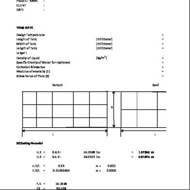
Rectangular 3z723n
September 2020 0
Reactions For Each Topic 2v1g5o
September 2020 0
Folded Plates 2o2l5i
November 2019 49
Predictor Plates 6k1c2t
November 2019 75More Documents from "Maitrayee Aditya" 6r2g3b

Cbr Report 1x6r4q
October 2019 96
February 2022 0

Norton Internet Security 2017 Trial Reset .pdf 1m2g5u
November 2019 35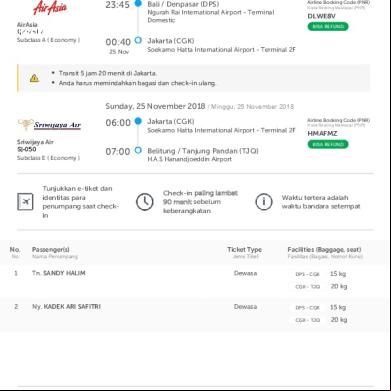
Aditya Kristianto Hotama Dps Dlwe8v, Hmafmz Tjq Flight_originating 5p6t2y
November 2019 11
Rencana Pelaksanaan Kegiatan (rpk) Tahunan 121j1c
July 2020 3