Ul 486-a Recommended Tightening Torque 4t3i3t
This document was ed by and they confirmed that they have the permission to share it. If you are author or own the copyright of this book, please report to us by using this report form. Report 3b7i
Overview 3e4r5l
& View Ul 486-a Recommended Tightening Torque as PDF for free.
More details w3441
- Words: 859
- Pages: 2
I
Informative Annex Recommended Tightening Torque Tables from UL Standard 486A-B This informative annex is not a part of the requirements of this NFPA document, but is included for informational purposes only.
In the absence of connector or equipment manufacturer’s recommended torque values, Table I.1, Table I.2, and Table I.3 may be used to correctly tighten screw-type connections for power and lighting circuits*. Control and signal
circuits may require different torque values, and the manufacturer should be ed for guidance. *For proper termination of conductors, it is very important that field connections be properly tightened. In the ab-
TABLE I.1 Tightening Torque for Screws Tightening Torque, N-m (lbf-in.) Slotted head No. 10 and largera Test Conductor Installed in Connector AWG or kcmil
mm2
30–10 8 6–4 3 2 1 1/0–2/0 3/0–4/0 250–350 400 500 600–750 800–1000 1250–2000
0.05–5.3 8.4 13.2–21.2 26.7 33.6 42.4 53.5–67.4 85.0–107.2 127–177 203 253 304–380 405–508 635–1010
Hexagonal head — external drive socket wrench
Slot width 1.2 mm (0.047 in.) Slot width over 1.2 mm or less and slot length 6.4 (0.047 in.) or slot length mm (1⁄4 in.) or less over 8.4 mm (1.4 in.) A 1.7 2.3 2.8 2.8 3.4
B (15) (20) (25) (25) (30)
— — — — — — — — —
2.3 2.8 4.0 4.0 4.5
A (20) (25) (35) (35) (40)
— — — — — — — — —
2.8 3.4 4.0 4.5 4.5 4.5 4.5 4.5 4.5 4.5 4.5 4.5 4.5
B (25) (30) (35) (40) (40) (40) (40) (40) (40) (40) (40) (40) (40)
—
4.0 4.5 5.1 5.6 5.6 5.6 5.6 5.6 5.6 5.6 5.6 5.6 5.6
(35) (40) (45) (50) (50) (50) (50) (50) (50) (50) (50) (50) (50) —
Split-bolt connectors A 7.3 7.3 15.3 25.4 25.4 25.4 35.6 45.2 62.1 76.3 76.3 90.4 111.7 111.7
(65) (65) (135) (225) (225) (225) (315) (400) (550) (675) (675) (800) (900) (900)
Other connectors
B 9.0 9.0 18.5 31.1 31.1 31.1 43.5 56.5 73.4 93.2 93.2 113.0 124.3 124.3
(80) (80) (165) (275) (275) (275) (385) (500) (650) (825) (825) (1000) (1100) (1100)
A 6.8 6.8 10.2 14.1 14.1 14.1 16.9 22.6 28.2 28.2 33.9 33.9 45.2 56.5
(60) (60) (90) (125 (125 (125 (150) (200) (250) (250) (300) (300) (400) (500)
B 8.5 8.5 12.4 16.9 16.9 16.9 20.3 28.2 36.7 36.7 42.4 42.4 56.5 67.8
(75) (75) (110) (150) (150) (150) (180) (250) (325) (325) (375) (375) (500) (600)
a For values of slot width or length not corresponding to those specified, select the largest torque value associated with the conductor size. Slot width is the nominal design value. Slot length shall be measured at the bottom of the slot.
1443
Informative Annex I
●
Recommended Tightening Torque Tables from UL Standard 486A-B
TABLE I.2 Tightening Torque for Slotted Head Screws Smaller Than No. 10 Intended for Use with 8 AWG (8.4 mm2) or Smaller Conductors Tightening Torque, N-m (lbf-in.) Slot width of screw smaller than 1.2 mm (0.047 in.)b
Slot Length of Screwa
Slot width of screw 1.2 mm (0.047 in.) and largerb
mm
in.
A
B
A
B
Less than 4 4 4.8 5.5 6.4 7.1 Above 7.1
Less than 5⁄32 5 ⁄32 3 ⁄16 7 ⁄32 1 ⁄4 9 ⁄32 Above 9⁄32
0.68 (6) 0.68 (6) 0.68 (6) 0.68 (6) 0.79 (7)
0.79 (7) 0.79 (7) 0.79 (7) 0.79 (7) 1.0 (9)
0.79 (7) 1.1 (10) 1.1 (10) 1.1 (10) 1.1 (10) 1.4 (12) 1.8 (15)
1.0 (9) 1.4 (12) 1.4 (12) 1.4 (12) 1.4 (12) 1.7 (15) 2.3 (20)
a
For slot lengths of intermediate values, select torques pertaining to next shorter slot lengths. Also, see 9.1.9.6 of UL 486A-B-2003 for screws with multiple tightening means. Slot length shall be measured at the bottom of the slot. b Slot width is the nominal design value.
TABLE I.3 Tightening Torque for Screws with Recessed Allen or Square Drives Socket Width Across Flatsa mm 3.2 4.0 4.8 5.5 6.4 7.9 9.5 12.7 14.3
Tightening Torque, N-m (lbf-in.)
in. 1
⁄8 ⁄32 3 ⁄16 7 ⁄32 1 ⁄4 5 ⁄16 3 ⁄8 1 ⁄2 9 ⁄16
5
A 4.0 9.0 11.3 13.5 16.9 25.4 33.9 45.2 56.5
B (35) (80) (100) (120) (150) (225) (300) (400) (500)
5.1 11.3 13.5 16.9 22.5 31.1 42.4 56.5 67.8
(45) (100) (120) (150) (200) (275) (375) (500) (600)
a
See 9.1.9.6 of UL 486A-B-2003 for screws with multiple tightening means. With the permission of Underwriters Laboratories, Inc., material is reproduced from UL Standard 486A-B, Wire Connectors, which is copyrighted by Underwriters Laboratories, Inc., Northbrook, Illinois. While use of this material has been authorized, UL shall not be responsible for the manner in which the information is presented, nor for any interpretations thereof. For more information on UL or to purchase standards, please visit our Standards website at www.comm-2000.com or call 1-888-853-3503.
sence of manufacturer’s instructions on the equipment, the torque values given in these tables are recommended. Because it is normal for some relaxation to occur in service,
1444
checking torque values sometime after installation is not a reliable means of determining the values of torque applied at installation.
2011
National Electrical Code Handbook
Related Documents 3m3m1z

Ul 486-a Recommended Tightening Torque 4t3i3t
December 2019 88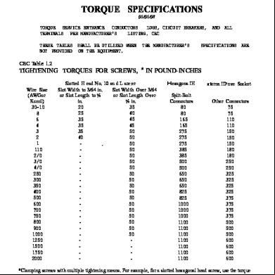
Tightening Torque s535q
December 2021 0
Ul 486a-1995.pdf 384i1h
November 2021 0
Anzugsdrehmoment - Tightening Torque i4x1b
May 2023 0
Bolt Tightening Torque Calculation 5v2cc
November 2019 166
Proper Barrel Tightening Torque r6q3o
November 2019 28More Documents from "JOSE LUIS FALCON CHAVEZ" 2x1d4g
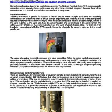
250-122 (f) Equipment-grounding Conductors For Parallel Runs 4a263x
November 2019 54
6l6m1j
December 2019 151
6l6m1j
May 2021 0
695 Nec Rules For Fire Pumps 736s6p
January 2022 0
400 Flexible Cords-nec 2008-mh 2v3y1o
December 2019 42