Tightening Torque s535q
This document was ed by and they confirmed that they have the permission to share it. If you are author or own the copyright of this book, please report to us by using this report form. Report 3b7i
Overview 3e4r5l
& View Tightening Torque as PDF for free.
More details w3441
- Words: 1,321
- Pages: 6
TORQUE SPECIFICATIONS 05/05/08
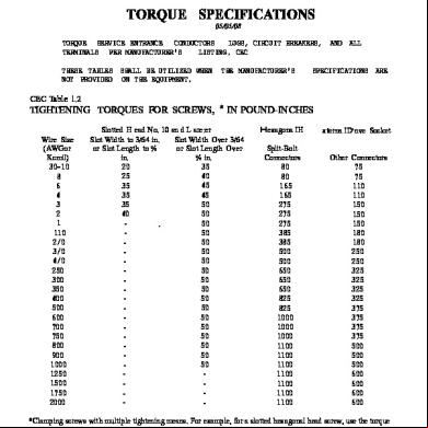
TORQUE SERVICE ENTRANCE CONDUCTORS LUGS, CIRCUIT BREAKERS, AND ALL TERMINALS PER MANUFACTURER'S LISTING. CEC 110.3(B),110.14 THESE TABLES SHALL BE UTILIZED WHEN THE MANUFACTURER'S SPECIFICATIONS ARE NOT PROVIDED ON THE EQUIPMENT. CEC Table 1.2
TIGHTENING TORQUES FOR SCREWS, * IN POUND-INCHES Wire Size (AWGor Kcmil)
30-10 8 6 4 3 2 1 110 2/0 3/0 4/0 250 300 350 400 500 600 700 750 800 900 1000 1250 1500 1750 2000
Slotted H ead No. 10 an d L are:er Slot Width to 3/64 in. Slot Width Over 3/64 or Slot Length to % or Slot Length Over in. % in.
20 25 35 35 35 40
-
-
-
-
-
.
35 40 45 45 50 50 50 50 50 50 50 50 50 50 50 50 50 50 50 50 50 50 -
-
Hexagona IH eadESplit-Bolt Connectors
80 80 165 165 275 275 275 385 385 500 500 650 650 650 825 825 1000 1000 1000 1100 1100 1100 1100 1100 1100 1100
xterna ID'nve Socket Other Connectors
75 75 110 110 150 150 150 180 180 250 250 325 325 325 325 375 375 375 375 500 500 500 600 600 600 600
*Clamping screws with multiple tightening means. For example, for a slotted hexagonal head screw, use the torque value associated with the tool used in the installation. UL uses both values when of slot width or length other than those specified, select the largest torque value associated with conductor size.
CEC Table 1.3
TORQUES IN POUND-INCHES FOR SLOTTED HEAD SCREWS *SMALLER THAN NO. 10, FOR USE WITH 8 AWG AND SMALLER CONDUCTORS Screw-Slot Length (in.)
Screw-Slot Width Less Than 3/64 in.
Screw-Slot Width 3/64 in. and Larger
To 5/32 5/23 3/16 7/32
Y4
7 7 7 7 9
9/32 Above 9/32
-
9 12 12 12 12 15 20
*Clamping screws with multiple tightening means. For example, for a slotted hexagonal head screw, use the torque value associated with the tool used in the installation. UL uses both values when testing. For slot lengths of .intermediate values, select torques pertaining to next-shorter slot length. CEC Table 1.4
CEC Table 1.5
TORQUES FOR RECESSED ALLEN HEAD SCREW S
LUG-BOLTING TORQUES FOR CONNECTIONS OF WIRE CONNECTORS TO BUSBARS
Socket Size Across Flat (in.) 118 5/32 3/16 7/32
V4 5/16 3/8 ~
9/16
Torque Bolt (lb-in.) 45 100 120 150 200 275 375 500 600
Bolt Diameter No.8 or smaller No. 10 V4 in. or less 5/16 in. 3/8 in. 7/16 in.
~i~ 9/16 in. or larger
Tightening Torque (lb-ft) 1.5 2 6 11 19 30 40 55
,
~
Torque Values for Graded -
Grade Tensile Strengfh
1/
SAE 1&2 44,000 PSI
Grade Mark
..
,
....;
..
::
.
Steel 8ol~s
SAE 5
SAE
SAE·8
(J
1"05,000 130,000 PSI
150,000
PSI
PSI
.
0 Q EB ©
, ,
;
.'~
i
"
Threads Per Inch
. .Bo]!
Diameter
,
Foot-Pounds Torque
..
1/4"
20
5
7
~Il I
10
5/16"
18
9
14
19
22
.3/8"
16
15
25
34
v'"
14,'
24
.40
' 55
60
13
37
60.1)/] J_ '
' 85
92
V ~-
.
7/16" '1/2"
1'"
'J
I '.~.
9/16"
12
53
88
.'120'
132
... ' 5/8~
11
74
120
1'69
180
3/4"
10
120
200
280
296
7/8"
9
190
302
440
473
1"
8
281"
463
660
714
"
The above values are based on approximately ,75% of yield strength, Fasteners must be lubricated (Petroleum Lubricant) . '. ~'.
,
.:
:
.
,
",
.,< .
~~'-'. ~_ .. "
.'
-.....
- ._
.
"
I
! ;
".
. f :
.. .,'
'.
r·
,
,:.:.. ..
..
;!Y--
,
I'
I
Bolt Torques for Buss Connections :
I
Grade Minimum Tensile Strength
SAE 1&2 64,000 PSI
Grade Mark
0
.
Threads Per Inch
Bolt Diameter
SAE 8 150,000 PSI
e~ 0 PSI
(J
V
Torque 8
B.4
15.2
17.6
~7.2
29.6
32.0
44,0
4B.O
29.6
48.0
68.0
73.6
12
42.4-
70.4
'96.0
105.6
5/8"
11
59.2
96.0
1.33.6
1.44.0
3/4"
10
96.0
160.0
224.0
236.B
7/B"
9
152.0
241.6
352.0
378.4
1,.
8
225.6
372.8
528.0
571.2
20
4
5.6
5/16"
18
7.2
11.2
3/8"
I6
tz.o
7/16"
14
19.2
1/2"
13
!
Ii
.
.
..
.
20.0
.,J'If.
'-
The above values ore based on approximately 75% of yield strength. Fasteners must be lubricated {Petroleum Lubricant) ./~
..'
~~'"
,I
.~
_J
-, Foct-Pounds
1/4"
9/16"
i·
SAE 6 133,000
SAE 5 105,000 PSI
•••# ......
,.
,!
\':
.'
:'1..'-·.~..".,. .
i. "
!
!
! i
-I
':._ .
.
...•.. _. _·n· ._ •..........
_:
._-:::...._._~_._•. _...•. _,._. _
_.
...
_r'
... _
,
_
.. ....•l.._._. _._"..
.._,_. ..._ .._..
,.
._
.•_ ...
I
i·;r"'-"~
, r . ·,1
'\
..._..... . .-~..-..--.-.---.---.--- .. - ~ -_.._ .._
_-_
;
.
'\
Connecting
Wire Torques
Screw Driver I
Wire AWG 18-10
. . "
{"
,"
Torque
Torque
1/8"
45
3.75
In-Lb
ft-Lb
2.9
40
3.34
5/32"
100
8.34
6-4
45
3.75
3/16.'
120
10
2-2/0
50
4.2.
7/32"
150
12.5·
.
.
:
.".
Torque
Across Flats
n-u
In-Lb
,
~
•..
Torque 35
8
'"
Socket Head
~
.
i-
1/4'"
200
.....- ...-.---:""-'---"
16.67 ..;_,:_
!--,,-'~--
5/1 ~"
275
22.9
3/8"
375
31.25
1/2"
500
41.67
9/16"
600
50
.I ;-,
. ,~.
. "
:! .S
:
~
.
j_
.
; .. ..
~< .,. ._.
. •_
• .
._.
.. ....•
._.
. • _.... ••.
' ••..
...
_••.• _.....
. _...
" ...•_.
... _ .._ ......
_ ..
_
'~~ N r I ~_ ASSEMBLY
POlARIS™ CONNECTORS
CONNECTOR SIZE
WIRE SIZE 1000 800-1000 550 600-750 550 450 500 400 350 250 4/0 3/0 2/0 1/0 #3-#1 #4-#6 #8 #10-#14
750 500 350 250 550 450 425 400 360
450 425 400 . 360 250 250 180 180 150 110
3/0
1/0
#4
TIGHTENING TORQUE IN INCH POUNDS
400 360 250 250 180 180· 150 110
360 250 250 180 180 150 110
250 180 180 180 150 150 110 110 45 75 40 35 35
See reverse for installation instructions and information witl:! regard to UL listing. Not recommended for use with fine-stranded, flexible wire. For fine-stranded, flexible wire, your distributor regarding Polaris Grey"'. A PROPERLY . INSTALLEDCONNECTORWILL HAVENOMORE THAN ONECONDUCTORPERPORT.
NSi INDUSTRIES,LLC • HUNTERSVILLE,NC • 800-321-5847 .
STANDARDCONNECTORS Wire insulation must be stripped in accordance with the chart below for standard Polaris™ Connectors. The wire insulation on a properly installed wire must be inside the insulated connector conductor port no less than 3/8 inch. Pressure screws must be secured at the torque value corresponding to the wire size and connector size shown on reverse side of this page. The UL listing applies for stranded wire only. AUCU 600V max for building wire and 1000V max for signs or fixtures. When installing Mounting Connectors, use the chart below to select the appropriate mounting bolt, not to exceed 80 in/lbs. . CUSTOM CONNECTORS When installing custom Polaris™ connectors, wire insulation must be stripped sucl that when the wire is inserted into the insulated connector conductor port, no less than 3/8 inch insulation is inside the conductor port. Insert the stripped wire until il stops against the back of the connector. CONNECTORSIZE STRIPE LENGTH BOLT DlA.JOR MOUNTING (IN.) 3-114 750MCM-H 5/16 . 2-5/16 5/16 ISRH 750 750MCM 2 5/16 500MCM 1-5/8 5/16 350MCM 1-3/8 5/16 1-1/4 5/16 250MCM 5116 250MCM-ISR H/8 1/4 3/0 AWG 1 7/8 1/4 1/0 AWG 11/16 3116 3/0 AWG Please note that some of the connector sizes and connector/wire size combinations shown on this sheet are not UL listed. Look for the UL Mark on the individual product to UL listed models and the correct wire sizes for the connector.
NSi INDUSTR~ES,LLC • HUNTERSVILLE, NC • 800-321-
Related Documents 3m3m1z
Tightening Torque s535q
December 2021 0
Anzugsdrehmoment - Tightening Torque i4x1b
May 2023 0
Bolt Tightening Torque Calculation 5v2cc
November 2019 166
Proper Barrel Tightening Torque r6q3o
November 2019 28
Bolt Tightening Torque Table 11b2w
May 2023 0
Ul 486-a Recommended Tightening Torque 4t3i3t
December 2019 88More Documents from "Shirish" y6n5t

How To Transfer A Flat In Housing Society Or Chs 1o1z28
November 2019 30
Liabilities Of A Principal Employer Under The Contract Labour 6qr1h
November 2019 50
Tightening Torque s535q
December 2021 0
Request For Noc To Avail Loan 66v1i
October 2021 0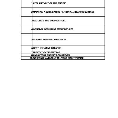
Dg Set Abcd Check 3s5a55
December 2019 50