Calgary 2011 Nozzle Loads Presentation 2b3y6
This document was ed by and they confirmed that they have the permission to share it. If you are author or own the copyright of this book, please report to us by using this report form. Report 3b7i
Overview 3e4r5l
& View Calgary 2011 Nozzle Loads Presentation as PDF for free.
More details w3441
- Words: 1,436
- Pages: 10
Piping (Nozzle) Loads. Applying the API 610 standards To A Centrifugal Pumpset {Pumpset = Pump + Baseplate}
Presented by: Doug Ingham, Sulzer Pumps (US) Inc.
API 610 {10th Edition} Requirements 5.3.3a
The pressure casing shall be designed to operate without leakage or internal between rotating and stationary components while subject simultaneously to the MAWP and the worst-case combination of twice (2x) the allowable nozzle loads of Table 4 applied through each nozzle.
NOTE: The twice-nozzle-load requirement is a pressure-casing design criterion. Other factors such as casing or baseplate stiffness affect allowable nozzle loads. 6.3.5
5.5.1
5.5.5
The pump and its baseplate shall be constructed with sufficient structural stiffness to limit displacement of the pump shaft at the drive end to meet values per API Table 12 when subjected to (1x) API 610 Table 4 nozzle moments. Three factors to consider: 1. Pump casing stress. Total to be within ASME allowable. (5.3.4) 2. Pump casing distortion. (5.3.3) 3. Misalignment of pump and driver shafts. (6.3.5) Annex F gives methods of qualifying nozzle loads in excess of those in Table 4. Annex F is used by the piping designer - not the pump designer. It also goes on to say that must be aware that the use of Annex F methods can result in 50% greater misalignment than would occur using the loads of Table 4
API 610 {10th Edition} Requirements 6.3.6
If specified, the vendor shall test to demonstrate that the pump and its baseplate assembly, anchored at foundation bolt hole locations, are in compliance with 6.3.5. The pump casing shall be subjected to moments MYC and MZC applied to either nozzle, but not both, such that the corresponding shaft displacements can be measured and recorded. MYC and MZC shall not be applied simultaneously to either nozzle. The shaft displacement measurements shall be absolute (not relative to the baseplate).
DY DZ
0.003" max
0.007" max
Nozzle Load Test at Pump Vendor's Facility Moments MYC & MZC are applied via a hydraulically operated rotary actuator. Shaft‐end movements are measured via dial indicators. Applied moment to suction nozzle for My Nozzle
Size (in)
MY (ft‐lb)
Suction
10
1800
MZ (ft‐lb) 2800
Discharge
6
870
1300
Calculated Moment Loads – (ft- lbs) MYc = MY (discharge) + MY (suction) = 870 + 1800 = 2670 MZc = MZ (discharge) + MZ (suction) = 1300 + 2800 = 4100
Measure deflection caused by My
Loading
MYc
MZc
Moment applied (ft‐lb)
2708
4166
Shaft displacement Dial indicator
(in)
Loading Condition MYc MZc
DZ
DY
0.0008
0.0005
Maximum allowable pump shaft displacements (in) Base intended for grout
Un‐grouted type base
DZ = 0.007
N/A
DY = 0.003
N/A
Purchaser's Requirements To reduce the complexity / cost of the supply / return piping design layout, purchasers request that pump suppliers modify the pumpset to accommodate higher nozzle loads. Question: When a purchaser specifies that the pump allowable nozzle loads shall be twice (2x) Table 4 values ‐ What does this actually mean? Option 1): A 2x multiplier must be applied to all paragraphs in API 610 that pertain to Table 4 nozzle loads: 5.3.3a The pressure casing shall be designed to operate without leakage or internal between rotating and stationary components while subject simultaneously to the MAWP and the worst‐case combination of four‐times (4x) the allowable nozzle loads of Table 4 applied through each nozzle. 6.3.5 The pump and its baseplate shall be constructed with sufficient structural stiffness to limit displacement of the pump shaft at the drive end to meet values per API Table 12 when subjected to (2x) API 610 Table 4 nozzle moments. F.1.2a) The individual component forces and moments acting on each pump nozzle flange shall not exceed the range specified in Table 4 by a factor more than 4. Option 2): A 2x multiplier is only applied to the shaft deflection criteria: 6.3.5 The pump and its baseplate shall be constructed with sufficient structural stiffness to limit displacement of the pump shaft at the drive end to meet values per API Table 12 when subjected to (2x) API 610 Table 4 nozzle moments.
Challenges For Pump Vendor When purchasers mandate the acceptance of nozzle loads in excess of API 610 Table 4 the pump vendor may be able to meet these requirements, however, this provision will require additional analysis, which may include a 3D casing Finite Element Analysis (FEA) at additional cost and increased lead time. The pump pressure casing may need to be modified. ASME flange ratings may need to be increased. {Use class 600# on a pump with a MAWP of 740 psig}. Pump pedestal and baseplate sub‐frame design will need to be modified. Analytical studies may find that it is not possible to meet acceptance criteria for reliable operation under the specified high nozzle load conditions.
Non-Standard Pump Nozzle Loads = Not a simple task:
Pump [Baseplate] Stiffness Evaluation •
The pump is considered stiff for the analysis. • •
• •
Unit loads are individually applied to the "stiffness center" of the pump The stiffness center is where the nozzles meet the pump casing; the nozzles can be considered to originate from this point and connect to the piping for the piping analysis.
Location of nozzles from the stiffness center (API coordinate system was used). The baseplate was analyzed with and without grout. • •
With grout, the baseplate was held at the anchor bolt locations and at the underside of the baseplate simulating bonded epoxy grout Without grout, the baseplate was held at the anchor bolts only.
FEA model of baseplate & pump with API coordinate system
Pump [Baseplate] Stiffness Evaluation Results Provide customer / piping designer with the information below and request re‐calculation of applied nozzle loads, considering the non‐rigid pump stiffness:
Load, Displacement, and Stiffness values for Baseplate & Pump
3-Dimensional FEA of Pump Case - Example • When considering acceptability of nozzle loads in excess of 2x API‐610 values, the aforementioned effects need to be investigated. • A finite element model of a 20 x 24 x 32 HSB casing was used to investigate the effect of high nozzle loads onto casing stresses and deflections.
3-Dimensional FEA of Pump Case - Example • •
The finite element model was subjected to 2,4,6 and 8 times API 610 Table‐4 nozzle loads. For each loading condition the model was checked for: – Casing stresses (absolute and change) – Case deformation around rotor seals. – Case tightness / potential for leakage – Pump hold‐down bolt stresses
3-Dimensional FEA of Pump Case - Example •
•
Several areas of concern were chosen for observation at each nozzle loading condition. These locations typically exhibited higher concentration of stress than its surrounding areas. Linearized stress paths were inserted at these locations. Stress distribution over the entire body was observed for abrupt changes between nozzle loadings.
3-Dimensional FEA of Pump Case - Stress Results
Case Material A216 Gr. WCB
Properties (psi) 36,000 Yield 70,000 Tensile
Conclusion: Nozzle loadings do not significantly influence stresses in the lower case half.
3-Dimensional FEA of Pump Case - Stress Results Upper Case #1
Upper Case #2
Case Material A216 Gr. WCB
Properties (psi) 36,000 Yield 70,000 Tensile
Ze ro Loa ding Internal Pressure Only (1480 psi)
psi
2X API % change
32,421 19,190
32,883 18,575
NOZZLE LOADINGS 4X API psi % change
psi
6X API % change
psi
8X API % change
UPPER CASE HALF STRESSES [Membrane + Bending] Pump Foot Upper Case #2 LowerCase#1 Upper Case #1
1.43 -3.20
32,762 19,115
1.05 -0.39
31,794 19,087
-1.93 -0.54
32,523 18,723
0.31 -2.43
Conclusion: Nozzle loadings do not significantly influence stresses in the upper case half.
3-Dimensional FEA of Pump Case - Deformation Evaluation
3-Dimensional FEA of Pump Case - Deformation Evaluation
Conclusion: Stationary wear ring does not come into with impeller eye ring under any tested loading condition.
3-Dimensional FEA of Pump Case - Gasket Tightness Evaluation
Gasket pressure must be maintained when the case is subjected distortion due to internal pressure and nozzle loads.
Pump vendors have specific criteria that needs to be checked.
3-Dimensional FEA of Pump Case - Gasket Tightness Evaluation
Conclusion: 1.) Gasket pressures around the parting flange bolt holes and mechanical seal bore are >= 2x maximum internal pressure. (Internal pressure is 1480 psi). 2.) No leakage is expected for 2x, 4x, 6x and 8x API‐610 nozzle loads. Relative change between load cases is insignificant.
3-Dimensional FEA of Pump Case - Hold-Down Bolt Evaluation
Bolt Material SAE Gr. 5
Properties (psi) 58,000 Yield 90,000 Tensile
Conclusion: Hold down bolts do not experience any significant change in stress.
Related Documents 3m3m1z

Calgary 2011 Nozzle Loads Presentation 2b3y6
December 2019 73
Nozzle Loads 2r355y
October 2019 205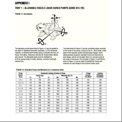
Allowable Nozzle Loads 5f2x4d
December 2019 290
Pressure Vessel Nozzle Loads ppz
February 2022 0
Calgary Listing Presentation 6m512y
December 2019 24