Presentation Upptcl 400kv Substation Motiram Adda, Gorakhpur 1a436e
This document was ed by and they confirmed that they have the permission to share it. If you are author or own the copyright of this book, please report to us by using this report form. Report 3b7i
Overview 3e4r5l
& View Presentation Upptcl 400kv Substation Motiram Adda, Gorakhpur as PDF for free.
More details w3441
- Words: 1,273
- Pages: 23
SUMMER TRAINING REPORT
ON 400KV SUBSTATION UTTAR PRADESH POWER TRANSMISSION CARPORATION LIMITED MOTTIRAM ADDA,GORAKHPUR(U.P.) SUBMITTED BY: RAHUL NAIN (EE) FINAL YEAR(1204210045)
Electric substation and its overview Single Line Diagram Isolator and switches Circuit breaker Lightning arrestor Current transformer Capacitive voltage transformer Protective relays Power transformer Control room and Relay room Battery room Wave trap Reference
Electrical Substation are mainly three types:1.Generating substation (Thermal , hydroelectric ,nuclear) 2.Transmission substation maintain symmetric configuration of conductor in each phase with proper transposition , use ACSR bundled conductor . 3.Receiving and Distribution substation Use ring main and radial distribution system.
The whole substation is divided in two parts: 400kv & 220kv site. The civil work is completed by L&T Company. Other part of project Design, Engineering, Manufacture, Supply, Erection, Testing and Commissioning of Bays is completed by CGL. • In 400/220kv switchyard following outdoor instrument used: Two 165MVA 220/132kv autotransformers one 315MVA 400/220kv autotransformer, one 250MVA autotransformer, Two 31.5MVAR shunt reactor,15 lighting tower, SF6 circuit breaker, Capacitor voltage transformer(CVT) Current transformer(CT). • In switchyard one room for emulsifire system and one for generator system is also present. In 400kv switchyards following lines are present for incoming and outgoing power. • 400kv Incoming 1. PGCIL I 2. PGCIL II (GIDA Sahjanwa) 3. UPPCL Azamgarh • 220kv Outgoing 1. Deoria 2. Baraunhua •
ISOLATORS USED IN SUB-STATION 1. Pentograph isolator:
For closing the linkage of pantograph are brought nearer by rotating the insulating column. and current is carried by upper bus bar to lower bus bar through conduction arm of pantograph. While opening rotating insulating column is rotated about its axes .so by blades collapse in vertical position and isolation is obtained.
2 . Double break isolator: Here central insulator stack can swing about its vertical axis about 90 degree. And provide double break.
1. load break switch Provide function of both isolator and switch and used for breaking load current. 2. Earth switch: Connected between line conductor and earth. Normally it is open. When line is disconnected the earth switch is closed so as to discharge the voltage trapped on the line Across capacitance between line and earth .
So before starting maintenance work these voltage are discharged to earth by closing the switch. They are mounted on the frame of isolator .
Sequence of operation of opening/closing switch : While opening: 1. Open circuit breaker 2.open isolator 3.close earth switch While closing: 1.open earth switch 2.close isolator 3.close circuit breaker So isolator operated only at no load condition.so not have any current making and breaking capacity .
•
•
A protective device for limiting surge voltages by discharging or bying surge current, and it also prevents the flow of follow current while remaining capable of repeating these functions. At the heart of all arresters is Metal Oxide Varistor (MOV). The MOV disk is a semiconductor that is sensitive to voltage. At normal voltage, the MOV disk is an insulator and will not conduct current. But at higher (extreme) voltage caused by lightning or any surges, it becomes a conductor.
Protective relay For switchyard protections following type relays are used:
1.Over current relay 2.Earth fault relay
3.Differential relay 4.Directional relay
5. Buchholz relay 6. IDMT relay
Overcurrent Relay: The relay which operates when the current exceeds the preset value is called the overcurrent relay. The preset value is called the pickup value. Types 1.Instantaneous overcurrent relay. As soon as fault occur relay operate. Operating time = .1 sec
4.very inverse relay here core does not saturate easily and on higher value of current time of operation become constant.
2.Inverse time current relay have inverse relation between acuating quantity and time of operation . DISTANCE RELAY
3.Inverse definite minimum time current relay as current increase more then time of operation become constant.
Buchholz relay:
The Buchholz Relay is used as a protective device sensitive to the effects of dielectric failure inside and inter turn fault in transformer.
Diffrential relay Used for the protection of alternator and transformer.
Operate when operation torque (i1s-i2s) is greater then pick up value.
REACTORS AND CAPACITOR : 1.SHUNT REACTOR Installed at sending and receiving end of line 2. SERIES REACTOR Installed at sending and receiving end of line and use to reduce Ferranti effect. and use to reduce current ripple.
3.Shunt capacitor Installed at receiving end to make receiving end voltage equal to sending end voltage.
CIRCUIT BREAKERS :Electrical circuit breaker is a switching device which can be operated manually as well as automatically for controlling and protection of electrical power system .
In this substation almost all the circuit breakers are SF6 type circuit breakers. There is a switchable series resistance along with the C.B. as shown here. It is inserted while closing the circuit breakers for a short time. This resistor, hence, limits the charging current of the line’s stray capacitance.
Circuit breaker operation
Differntiation between power transformer and distribution transformer 1. Power transformer are operated on full load or are switched while distribution transformer are operated at 70 to 75% full load capacity.
2.Power transformer efficiency is design for full load operation so iron loss has higher value than distribution transformer.
3.Power transformer has small size. than distribution transformer . Because higher flux density in result in smaller area.
POWER TRANSFORMER USED AT SUBSTATION -
This substation has two type of power transformers: 1) 400 KV 220 KV and 2) 220 KV 132 KV The cooling system employed is forced air – forced oil. The cooling systems of transformers are automatically controlled. Once the temperature reaches 70 C, the cooling system starts and as temperature reaches 60 C, the systems switches OFF. The supply to the cooling system is given from the substation supply transformer
315MVA Transformer
220 KVA TRANSFORMER
•
•
The control s and relays of the substation require DC supply of 220 V. This DC supply is made with the help of battery bank reserve normally kept in a separate room called Battery room. The batteries used in this substation are Nickel-Cium (Ni-Cd) batteries.
Current transformer: Current Transformers (CT’s) are instrument transformers that are used to supply a reduced value of current to meters, protective relays, and other instruments. CT’s provide isolation from the high voltage primary, permit grounding of the secondary for safety, and step-down the magnitude of the measured current to a value that can be safely handled by the instruments.
.
Error: 1.Ratio error Happen due to no load current component. 2. Phase angle error : Due to not having exactly 180 degree phase angle difference between primary and reverse secondary current.
Capacitor voltage transformer
In high and extra high voltage transmission systems, capacitor voltage transformers (CVTs) are used to provide potential outputs to metering instruments and protective relays.
Wave trap:•As the communication signal frequency is much different from line frequency and also the voltage level is too low, it is quite necessary to separate the power signal and communication signal. •This task is performed by a wave trap which simply consists of L-C series and parallel •A wave trap is used on those transmission lines which are equipped with PLCC (Power Line Carrier Communication). Filters.
Through this training I come to about transmitting substation working . The Uttar Pradesh Power Corporation Limited has got radio communication in microwave range in order to transmit and receive data with various Substations in Uttar Pradesh to get reliable transmission and distribution of electricity.
•
C.L.Wadhwa “Electrical Power System”, 6th Edition
•
Wikipedia
•
Power Station Manual Of UPPCL, Motiram adda, Gorakhpur
. Switch gear and protection by “sunil.s.rao”.
Related Documents 3m3m1z
Presentation Upptcl 400kv Substation Motiram Adda, Gorakhpur 1a436e
August 2021 0
400kv Substation Training Report 5rd3a
December 2019 87
Basic Of 400kv Substation Design 3a3o32
October 2019 141
Gas Insulated Substation Presentation 5n6x3p
April 2020 20
Presentation On Substation 220 Kv 2m1j2f
December 2019 79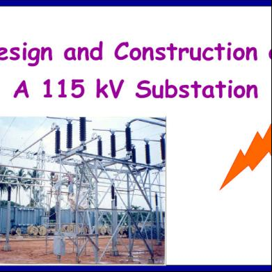
115 Kv Substation Design Presentation 5v3h5m
April 2022 0More Documents from "Anik Goyal" 2l6g61
Power Electronics Made Easy 6gi57
December 2019 85
Presentation Upptcl 400kv Substation Motiram Adda, Gorakhpur 1a436e
August 2021 0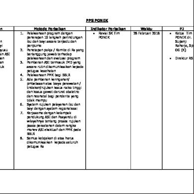
Pps Ponek.docx 4e4w3r
July 2020 0
4 Regulasi Keperawatan 591q1v
April 2020 22
Knowledge Representation Using Rules 4z412d
November 2019 59